Embed Size (px)
Citation preview

This publication is not intended fordistribution in the USA.
Instruments and implants approved by the AO Foundation
LCP Ulna Osteotomy System 2.7. Low profile angular stable fixation forulna shortening osteotomies.
Technique Guide


Table of Contents
Introduction
Surgical Technique
Product Information
LCP Ulna Osteotomy System 2.7 2
Indications 4
AO Principles 5
Preoperative Planning 6
Preparation and Approach 7
Position and Fix Drill Template 8
A Transverse Osteotomy 10
B Oblique Osteotomy 18
Final Fixation of Locking Screws 30
Alternative Technique 31
Implant Removal 34
Implants 35
Instruments 36
Image intensifier control
WarningThis description alone does not provide sufficient background for direct use ofthe instrument set. Instruction by a surgeon experienced in handling theseinstruments is highly recommended.
Reprocessing, Care and Maintenance of Synthes InstrumentsFor general guidelines, function control and dismantling of multi-part instruments,please contact your local sales representative or refer to:www.synthes.com/reprocessing
LCP Ulna Osteotomy System 2.7 Technique Guide DePuySynthes 1

LCP Ulna Osteotomy System 2.7. Low profile angular stable fixation forulna shortening osteotomies.
Low profile angular stable plates– With rounded edges and tapered ends to minimize risk of soft tissue irritation
– Stable fixation with � 2.7 mm locking and cortex screws– Available in stainless steel or titanium alloy
Parallel saw blades for transverseand oblique osteotomy cuts– Available for transverse and obliqueosteotomy cuts in five differentwidths for 2, 2.5, 3, 4 and 5 mmshortening
– For precise parallel osteotomy cuts– Compatible with Synthes Colibriwith Oscillating Saw Attachment
Drill templates– For predrilling of plate fixation holes beforeosteotomy cut to ensure correct rotationalalignment
– Saw guide can be mounted for easier startof 45° oblique osteotomy cut
2 DePuySynthes LCP Ulna Osteotomy System 2.7 Technique Guide

1
2
3
Designed for transverse andoblique osteotomiesThree-part combi-hole for flexiblescrew placement:– Lag screw for use in oblique osteotomies (1)
– Neutral cortex screw (2)– Locking screw (3)– Symmetric plate design
Compression/distraction instrument– Allows for compression and distrac-tion after the osteotomy
– For Kirschner Wires up to � 2.0 mm– To aid in reduction and compressionof the cut bone ends
– Two fixation options on each side ofthe osteotomy
– Can be used in combination withdrill templates
– Freehand application for shortenings >5 mm
� 2.7 mmLocking screw
� 2.7 mmCortex screw
LCP Ulna Osteotomy System 2.7 Technique Guide DePuySynthes 3

Indications
Primary ulnar impaction syndrome– Degenerative triangular fibrocartilage complex (TFCC)tears
– Lunotriquetral tears
Secondary ulnar impaction syndrome– Incongruency (length discrepancy) of the distal radial-ulnarjoint following distal radius fracture
– Traumatic triangular fibrocartilage complex (TFCC) tears
4 DePuySynthes LCP Ulna Osteotomy System 2.7 Technique Guide

AO Principles
AO PrinciplesIn 1958, the AO formulated four basic principles, which havebecome the guidelines for internal fixation.1 Those principlesas applied to the LCP Ulna Osteotomy System 2.7 are:
Anatomic reductionFracture reduction and fixation to restore anatomical relationships.
Stable fixationStability by fixation or splintage, as the personality of thefracture and injury requires.
Preservation of blood supplyPreservation of the blood supply to soft tissue and bone bycareful handling.
Early, active mobilizationEarly and safe mobilization of the part and the patient.
1 ME Müller, M Allgöwer, R Schneider, and H Willenegger: Manual of Internal Fixation, 3rd Edition. Berlin: Springer-Verlag. 1991.
LCP Ulna Osteotomy System 2.7 Technique Guide DePuySynthes 5

034.
000.
658
AA
30
1001
27
© 0
2/20
10 S
ynth
es, I
nc.
or
its
affi
liate
s A
ll ri
gh
ts r
eser
ved
Sy
nth
es a
nd
LC
P ar
e tr
adem
arks
of
Syn
thes
, In
c. o
r it
s af
filia
tes
For use only with the Original AO System ofInstruments and Implants
Synthes GmbHEimattstrasse 3CH-4436 Oberdorfwww.synthes.com
LCP Ulna Osteotomy Plate 2.7
1.10 Magnification
Holes0X.111.900 60X.111.901 8
AP
Vie
wLa
tera
l Vie
w
Ö034.000.658_AA&ä
X=2: Stainless SteelX=4: Titanium Alloy (TAN)
0 10 20 30 40 50 60 70 80 90 100 mm
Complete preoperative radiographic assessment and preoperative planning is essential, especially in cases of secondary impaction.
Contralateral x-rays allow determination of the necessaryamount of shortening.
The LCP Ulna Osteotomy Plate 2.7 is intended to be placedon the volar flat surface of the ulna, just proximal to thepronator quadratus muscle. It is recommended to place theplate between the distal and the middle third of the ulnarshaft.
Alternative plate placement, i.e. on the dorsal aspect is alsopossible.
The plate may be contoured for proper placement on thebone. To preserve the strength of the plate, avoid repetitivebending.
Option: In specific cases, the use of the x-ray template forthe LCP Ulna Osteotomy Plate 2.7 (Art. No. 034.000.658)may be helpful.
Preoperative Planning
6 DePuySynthes LCP Ulna Osteotomy System 2.7 Technique Guide

1Patient positioning
Place the patient in a supine position with the forearm positioned on a hand table in full supination and the shoulder in 90° abduction. The use of a tourniquet and magnifying loops is recommended.
Preparation and Approach
2Approach
Make a longitudinal incision to approach the volar side ofthe ulna.
Note: Take care not to damage the dorsal sensory branch of the ulnar nerve.
LCP Ulna Osteotomy System 2.7 Technique Guide DePuySynthes 7
10 mm15 mm
3 21
Position and Fix Drill Template
Instruments
03.111.900 Drill Template for LCP Ulna Osteotomy Plate 2.7, for 2.0 mm shortening
03.111.901 Drill Template for LCP Ulna Osteotomy Plate 2.7, for 2.5 mm shortening
03.111.902 Drill Template for LCP Ulna Osteotomy Plate 2.7, for 3.0 mm shortening
03.111.903 Drill Template for LCP Ulna Osteotomy Plate 2.7, for 4.0 mm shortening
03.111.904 Drill Template for LCP Ulna Osteotomy Plate 2.7, for 5.0 mm shortening
02.111.902.01 Kirschner Wire � 2.0 mm with drill tip, length 100 mm, Stainless Steel
02.111.903.01 Kirschner Wire � 2.0 mm with drill tip, length 150 mm, Stainless Steel
Choose the drill template according to the intended amountof shortening.
Position the drill template on the bone and fix it bicorticallywith the Kirschner wires � 2.0 mm with drill tip. Two lengthsof Kirschner wires are available. For the fixation of the drilltemplate at both ends, start distally and use 100 mmKirschner wires (02.111.902.01 12) to avoid space con-straints when inserting the third, 150 mm Kirschner wire(02.111.903.01 3).The circular laser markings on the Kirschner wires can beused as a guide for insertion depth: the first marking indicates insertion depth 10 mm, the second marking 15 mm(reading at the edge of the drill template).
Precaution: Do not start drilling before Kirschner wire tip isin contact with the bone. Avoid off-axis insertion of theKirschner wire.
distalproximal
8 DePuySynthes LCP Ulna Osteotomy System 2.7 Technique Guide

Notes:– Make sure the drill template is correctly oriented proximally and distally according to the etchings.
– The shape of the drill template is identical to the shape of the 6-hole LCP Ulna Osteotomy Plate(02.111.900/04.111.900).
– Ensure that the drill template lies centrally on the bone for proper plate placement.
– Confirm the placement of the drill template with the image intensifier.
Important:– Both ends of the drill template should sit flush on thebone when inserting the Kirschner wires; otherwise theplate may need to be bent to fit the patient anatomy.
– If the ulnar bone is slightly convex, the drill template maynot sit flush on the bone and could tilt. If the template istilting, ensure that the distal end is kept flush on the bonewhen inserting the Kirschner wires.
Flush
Tilting
distal proximal
LCP Ulna Osteotomy System 2.7 Technique Guide DePuySynthes 9
1
2
3
A Transverse Osteotomy
1Perform transverse osteotomy
Instruments for transverse osteotomy cut
532.081S Saw Blade, parallel, 47.1/25�12�2.0 mm, cut 90°, shortening 2.0 mm, sterile
532.082S Saw Blade, parallel, 47.1/25�12�2.5 mm, cut 90°, shortening 2.5 mm, sterile
532.083S Saw Blade, parallel, 47.1/25�12�3.0 mm, cut 90°, shortening 3.0 mm, sterile
532.084S Saw Blade, parallel, 47.1/25�12�4.0 mm, cut 90°, shortening 4.0 mm, sterile
532.085S Saw Blade, parallel, 47.1/25�12�5.0 mm cut 90°, shortening 5.0 mm, sterile
Optional instrument
399.082 Reduction Forceps, toothed, soft lock, length 146 mm
The following features are etched on the parallel saw blade:1 90° transverse cut2� Amount of shortening (mm)3� Effective saw blade distance
10 DePuySynthes LCP Ulna Osteotomy System 2.7 Technique Guide

Choose an appropriate parallel saw blade for transverse os-teotomy (90°) and intended amount of shortening. Be surethat the parallel saw blade and the drill template are in-tended for the same amount of shortening. Before startingthe osteotomy, ensure that the parallel saw blade spacer is inthe correct position, away from the coupling part.
Notes:– Protect the soft tissue behind the far cortex.– Avoid applying excessive force while making the osteotomy cut.
– Irrigate during sawing to avoid excessive heating.
Important: Make sure that the cut is always perpendicularto the long axis of the bone.
Align the parallel saw blade with the transverse parallelmarkings on the drill template and perform the osteotomycut. The markings on the drill template indicate the correctpositioning of the saw blade.
Perform the osteotomy with the drill template in contactwith the bone and the parallel saw blade in motion. Do notshift the direction of the saw blade once cut has beenstarted. Once cutting has been started, advancement of thesaw blade may be easier when the drill template is slid awayfrom the bone by 2-3 mm.
Option: To avoid shifting of the drill template due to vibra-tion, it may be provisionally fixed with reduction forceps.
Transverse cut
LCP Ulna Osteotomy System 2.7 Technique Guide DePuySynthes 11

2Remove drill template and place plate
Remove the drill template and place the plate over theKirschner wires. Reduction of the osteotomy can be achieved by ulnar abduction of the wrist joint or by usinga reduction clamp.
Note: Correct plate positioning is important. Always includethe oblong combi-holes with the most proximal and themost distal Kirschner wires.
A Transverse Osteotomy
12 DePuySynthes LCP Ulna Osteotomy System 2.7 Technique Guide

3Fix plate with cortex and locking screws
Technique tips: – In young patients with dense cortical bone, screw inser-tion might be difficult. To make screw insertion easier, thescrew can be turned counterclockwise once or twice andreinserted again.
– Alternatively, a tap prior to screw insertion can be used.Two different taps are available: a tap for cortex screws � 2.7 mm (311.260) and a tap for locking screws � 2.7 mm (03.111.906). To differentiate the two taps,laser markings and a color-coded band are indicated onthe tap for locking screws.
– It is recommended to use the tap manually. As a generalrule, the tap is turned twice clockwise and once counter-clockwise to allow bone debris to collect in the flutes.
– When inserting a screw in a pretapped hole, use care during insertion and do not apply off-axis load.
Tap for Cortex Screws � 2.7 mm (311.260)
Tap for Locking Screws � 2.7 mm (03.111.906)
LCP Ulna Osteotomy System 2.7 Technique Guide DePuySynthes 13

1
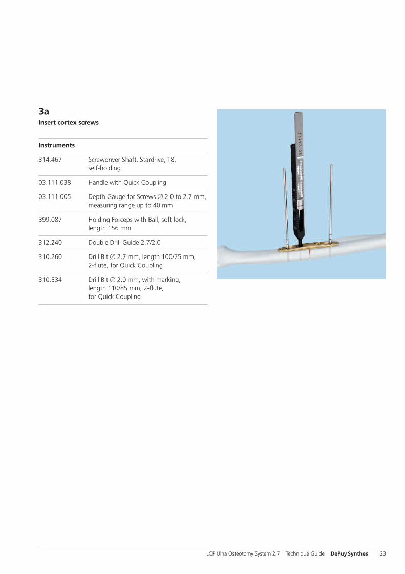
3aInsert cortex screws
Instruments
314.467 Screwdriver Shaft, Stardrive, T8, self-holding
03.111.038 Handle with Quick Coupling
03.111.005 Depth Gauge for Screws � 2.0 to 2.7 mm, measuring range up to 40 mm
399.087 Holding Forceps with Ball, soft lock, length 156 mm
Optional instruments
314.453 Screwdriver Shaft Stardrive 2.4, short, self-holding, for Quick Coupling
311.260 Tap for Cortex Screws � 2.7 mm, length 100/33 mm
399.082 Reduction Forceps, toothed, soft lock, length 146 mm
Remove the Kirschner wire located distal to the osteotomy.Measure screw length and insert the correct length � 2.7 mm cortex screw using the self-holding T8 Stardrivescrewdriver shaft and the quick coupling handle 1.
Note: Make sure that the screw does not engage thethreaded part of the screw hole. It must be tightened in neutral position in the non-threaded part of the screw hole.
A Transverse Osteotomy
14 DePuySynthes LCP Ulna Osteotomy System 2.7 Technique Guide

2
4
1
3
2 1
2 13
Remove the most distal Kirschner wire, measure the screwlength and insert the correct length � 2.7 mm cortex screw 2 (1).
Before removing the proximal Kirschner wire, fix the plate inposition with the holding forceps with ball. Place the forcepsin the most proximal plate hole (2).
Option: To additionally secure axial alignment of the twofragments, reduction forceps can be used (e.g. 399.082) (3).Remove the Kirschner wire proximal to the osteotomy 3,measure the screw length and insert the correct length � 2.7 mm cortex screw (4). Remove the holding forceps withball when tightening the screw and apply compression to the osteotomy.
Notes:– The screw hole for the third cortex screw (proximal to theosteotomy) is located in eccentric position of the oblongcombi-hole. Tightening of this screw will apply compres-sion to the osteotomy.
– Make sure that the osteotomy gap is completely closed.
Important:– Consider using a tap in case of very hard ulnar bone (see technique tip page 13).
– Insertion of the eccentric screw may be facilitated byslightly loosening the cortex screws distally.
LCP Ulna Osteotomy System 2.7 Technique Guide DePuySynthes 15

3bInsert locking screws
Instruments
323.033 LCP Drill Sleeve for LCP Screws � 2.7 mm (head LCP 2.4), with Scale up to 30 mm, for Drill Bits � 2.0 mm
310.534 Drill Bit � 2.0 mm, with marking, length 110/85 mm, 2-flute, for Quick Coupling
03.111.005 Depth Gauge for Screws � 2.0 to 2.7 mm, measuring range up to 40 mm
314.467 Screwdriver Shaft, Stardrive, T8, self-holding
03.111.038 Handle with Quick Coupling
Optional instruments
03.111.906 Tap for Locking Screws � 2.7 mm, length 100/33 mm
314.453 Screwdriver Shaft Stardrive 2.4, short, self-holding, for Quick Coupling
Screw the LCP drill sleeve into the most distal locking holeuntil fully seated.
Use the � 2.0 mm drill bit to drill to the desired depth.
Measure the screw length either by using the scale on thedrill bit or by using the depth gauge.
A Transverse Osteotomy
16 DePuySynthes LCP Ulna Osteotomy System 2.7 Technique Guide

Insert the correct length locking screw manually with the self-holding T8 Stardrive screwdriver shaft and quick coupling handle.
Note: Do not yet fully tighten the screw to lock. For thelocking of locking screws, see page 30.
Insert additional locking screws as planned. If additional fixation is needed, the elongated hole may be filled with twoscrews.
6-Hole plate
8-Hole plate
LCP Ulna Osteotomy System 2.7 Technique Guide DePuySynthes 17

1
2
3
B Oblique Osteotomy
1Perform oblique osteotomy
Instruments for oblique osteotomy cut
532.091S Saw Blade, parallel, 47.1/25�12�1.4 mm, cut 45°, shortening 2.0 mm, sterile
532.092S Saw Blade, parallel, 47.1/25�12�1.8 mm, cut 45°, shortening 2.5 mm, sterile
532.093S Saw Blade, parallel, 47.1/25�12�2.1 mm, cut 45°, shortening 3.0 mm, sterile
532.094S Saw Blade, parallel, 47.1/25�12�2.8 mm, cut 45°, shortening 4.0 mm, sterile
532.095S Saw Blade, parallel, 47.1/25�12�3.5 mm, cut 45°, shortening 5.0 mm, sterile
Optional instruments
399.082 Reduction Forceps, toothed, soft lock, length 146 mm
03.111.905 Saw Guide for LCP Ulna Osteotomy Plate 2.7
511.776 Torque limiter, 0.8 Nm, with AO/ASIF Quick Coupling
314.467 Screwdriver Shaft, Stardrive, T8, self-holding
03.110.005 Handle for Torque Limiters 0.4/0.8/1.2 Nm
The following features are etched on the parallel saw blade:1�45° oblique cut2�Amount of shortening (mm)3�Effective saw blade distance
18 DePuySynthes LCP Ulna Osteotomy System 2.7 Technique Guide

1 2
Choose an appropriate parallel saw blade for oblique os-teotomy (45°) and intended amount of shortening. Be surethat the parallel saw blade and the drill template are in-tended for the same amount of shortening. Before startingthe osteotomy, ensure that the parallel saw blade spacer is inthe correct position, away from the coupling part.
Notes:– Protect the soft tissue behind the far cortex.– Avoid applying excessive force while making the osteotomy cut.
– Irrigate during sawing to avoid excessive heating.– Make sure that the cut is always perpendicular to the longaxis of the bone.
Option: To indicate the correct angle for the 45° oblique cut,a saw guide can be mounted on the drill template (1). Note: In this case use the screwdriver together with the 0.8 Nm Torque Limiter to tighten the screw (2). To untightenthe screw, use the screwdriver only without the torque limiter.
LCP Ulna Osteotomy System 2.7 Technique Guide DePuySynthes 19

3
4
B Oblique Osteotomy
20 DePuySynthes LCP Ulna Osteotomy System 2.7 Technique Guide
Align the parallel saw blade with the oblique parallel mark-ings on the drill template and perform the osteotomy cut.The markings on the drill template indicate the correct posi-tioning of the saw blade.
Perform the osteotomy with the drill template in contactwith the bone and the parallel saw blade in motion. Do notshift the direction of the saw blade once cutting has beenstarted. Once cutting has been started, advancement of thesaw blade may be easier when the drill template is slid awayfrom the bone by 2–3 mm (4).
Option: To avoid shifting of the drill template due to vibra-tion, it may be provisionally fixed with reduction forceps (3).
Oblique cut

2Remove drill template and place plate
Remove the drill template and place the plate over theKirschner wires. Reduction of the osteotomy can be achieved by ulnar abduction of the wrist joint or by using a reduction clamp.
Note: Correct plate positioning is important. Always includethe oblong combi-holes with the most proximal and themost distal Kirschner wires.
LCP Ulna Osteotomy System 2.7 Technique Guide DePuySynthes 21

B Oblique Osteotomy
22 DePuySynthes LCP Ulna Osteotomy System 2.7 Technique Guide
3Fix plate with cortex and locking screws
Technique tips:– In young patients with dense cortical bone, screw inser-tion might be difficult. To make screw insertion easier, thescrew can be turned counterclockwise once or twice andreinserted again.
– Alternatively, a tap prior to screw insertion can be used.Two different taps are available: a tap for cortex screws � 2.7 mm (311.260) and a tap for locking screws � 2.7 mm (03.111.906).
– To differentiate the two taps, laser markings and a color-coded band are indicated on the tap for locking screws.
– It is recommended to use the tap manually. As a generalrule, the tap is turned twice clockwise and once counter-clockwise to allow bone debris to collect in the flutes.
– When inserting a screw in a pretapped hole, use care during insertion and do not apply off-axis load.
Tap for Cortex Screws � 2.7 mm (311.260)
Tap for Locking Screws � 2.7 mm (03.111.906)
3aInsert cortex screws
Instruments
314.467 Screwdriver Shaft, Stardrive, T8, self-holding
03.111.038 Handle with Quick Coupling
03.111.005 Depth Gauge for Screws � 2.0 to 2.7 mm, measuring range up to 40 mm
399.087 Holding Forceps with Ball, soft lock, length 156 mm
312.240 Double Drill Guide 2.7/2.0
310.260 Drill Bit � 2.7 mm, length 100/75 mm, 2-flute, for Quick Coupling
310.534 Drill Bit � 2.0 mm, with marking, length 110/85 mm, 2-flute, for Quick Coupling
LCP Ulna Osteotomy System 2.7 Technique Guide DePuySynthes 23

1
B Oblique Osteotomy
24 DePuySynthes LCP Ulna Osteotomy System 2.7 Technique Guide
Optional instruments
314.453 Screwdriver Shaft Stardrive 2.4, short, self-holding, for Quick Coupling
323.260 Universal Drill Guide 2.7
311.260 Tap for Cortex Screws � 2.7 mm, length 100/33 mm
399.082 Reduction Forceps, toothed, soft lock, length 146 mm
Remove the Kirschner wire located distal to the osteotomy.Measure the screw length and insert the correct length � 2.7 mm cortex screw using the self-holding T8 Stardrivescrewdriver shaft and the quick coupling handle 1.
Note: Make sure that the screw does not engage thethreaded part of the screw hole. It must be tightened in -neutral position in the non-threaded part of the screw hole.

2
4
1
3
12
123
LCP Ulna Osteotomy System 2.7 Technique Guide DePuySynthes 25
Remove the most distal Kirschner wire, measure the screw length and insert the correct length � 2.7 mm cortexscrew 2 (1).
Before removing the proximal Kirschner wire, fix the plate inposition with the holding forceps with ball. Place the forcepsin the most proximal plate hole (2).
Option: To additionally secure axial alignment of the twofragments, reduction forceps can be used (e.g. 399.082) (3).Remove the Kirschner wire proximal to the osteotomy 3,measure the screw length and insert the correct length � 2.7 mm cortex screw (4). Remove the holding forceps withball when tightening the screw and apply compression to theosteotomy.
Notes:– The screw hole for the third cortex screw (proximal to theosteotomy) is located in eccentric position of the oblongcombi-hole. Tightening of this screw will apply compres-sion to the osteotomy.
– Make sure that the osteotomy gap is completely closed.
Important:– Consider using a tap in case of very hard ulnar bone (see technique tip page 22).
– Insertion of the eccentric screw may be facilitated byslightly loosening the cortex screws distally.

B Oblique Osteotomy
26 DePuySynthes LCP Ulna Osteotomy System 2.7 Technique Guide
If a lag screw is desired, use the following technique:
Overdrill the near cortex using the double drill guide 2.7 andthe drill bit � 2.7 mm.
Drill the threaded hole using the double drill guide 2.0 andthe drill bit � 2.0 mm.
Measure the screw length using the depth gauge.

LCP Ulna Osteotomy System 2.7 Technique Guide DePuySynthes 27
Select and insert the correct length � 2.7 mm cortex screwas a lag screw using the T8 screwdriver shaft and the handlewith quick coupling.

28 DePuySynthes LCP Ulna Osteotomy System 2.7 Technique Guide
B Oblique Osteotomy
3bInsert locking screws
Instruments
323.033 LCP Drill Sleeve for LCP Screws � 2.7 mm (head LCP 2.4), with Scale up to 30 mm, for Drill Bits � 2.0 mm
310.534 Drill Bit � 2.0 mm, with marking, length 110/85 mm, 2-flute, for Quick Coupling
03.111.005 Depth Gauge for Screws � 2.0 to 2.7 mm, measuring range up to 40 mm
314.467 Screwdriver Shaft, Stardrive, T8, self-holding
03.111.038 Handle with Quick Coupling
Optional instruments
03.111.906 Tap for Locking Screws � 2.7 mm, length 100/33 mm
314.453 Screwdriver Shaft Stardrive 2.4, short, self-holding, for Quick Coupling
Screw the LCP drill sleeve into the most distal locking holeuntil fully seated.
Use the 2.0 mm � drill bit to drill to the desired depth.
Measure the screw length either by using the scale on thedrill bit or by using the depth gauge.

LCP Ulna Osteotomy System 2.7 Technique Guide DePuySynthes 29
Insert the correct length locking screw manually with theself-holding T8 Stardrive screwdriver shaft and quick coup -ling handle.
Note: Do not yet fully tighten the screw to lock. For the locking of locking screws, see the following page.
Insert additional locking screws as planned. If additional fixation is needed, the elongated hole may be filled with twoscrews.
6-Hole plate
8-Hole plate

30 DePuySynthes LCP Ulna Osteotomy System 2.7 Technique Guide
Final Fixation of Locking Screws
Perform final fixation of locking screws
Instruments
03.110.005 Handle for Torque Limiters 0.4/0.8/1.2 Nm
511.776 Torque Limiter, 0.8 Nm, with AO Quick Coupling
314.453 Screwdriver Shaft Stardrive 2.4, short, self-holding, for Quick Coupling
Optional instrument
314.467 Screwdriver Shaft, Stardrive, T8, self-holding
Use the 0.8 Nm torque limiter to perform the final lockingstep for locking screws.
The torque limiter prevents overtightening and ensures thatthe locking screws are securely locked into the plate.
Assemble the torque limiter and the handle for torque limiterand tighten the locking screws using the self-holding T8 Stardrive screwdriver shaft.
If the torque limiter releases prior to final locking, the use ofa tap is recommended (see technique tips on pages 13 and22, respectively).
AB A B
11
21
LCP Ulna Osteotomy System 2.7 Technique Guide DePuySynthes 31
Alternative Technique
Use of compression/distraction instrument
Instruments
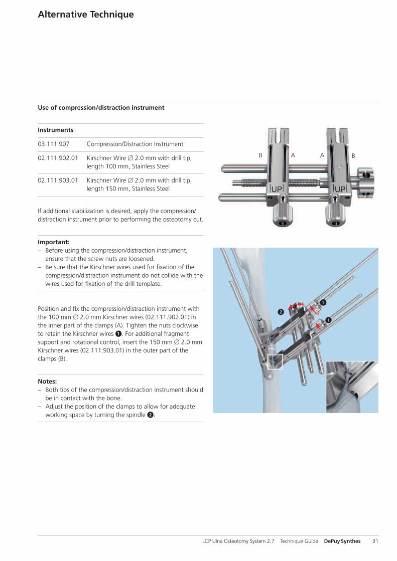
03.111.907 Compression/Distraction Instrument
02.111.902.01 Kirschner Wire � 2.0 mm with drill tip, length 100 mm, Stainless Steel
02.111.903.01 Kirschner Wire � 2.0 mm with drill tip, length 150 mm, Stainless Steel
If additional stabilization is desired, apply the compression/distraction instrument prior to performing the osteotomy cut.
Important:– Before using the compression/distraction instrument, ensure that the screw nuts are loosened.
– Be sure that the Kirschner wires used for fixation of thecompression/distraction instrument do not collide with thewires used for fixation of the drill template.
Position and fix the compression/distraction instrument withthe 100 mm � 2.0 mm Kirschner wires (02.111.902.01) inthe inner part of the clamps (A). Tighten the nuts clockwiseto retain the Kirschner wires 1. For additional fragment support and rotational control, insert the 150 mm � 2.0 mmKirschner wires (02.111.903.01) in the outer part of theclamps (B).
Notes:– Both tips of the compression/distraction instrument shouldbe in contact with the bone.
– Adjust the position of the clamps to allow for adequateworking space by turning the spindle 2.

15 mm10 mm
32 DePuySynthes LCP Ulna Osteotomy System 2.7 Technique Guide
Alternative Technique
For an oblique cut, it might be necessary to remove the sawguide to apply the compression/distraction instrument. Thecut can be marked before the compression/distraction instru-ment is applied.
The circular laser markings on the Kirschner wires can beused as approximate indication for insertion depth: the first marking indicates insertion depth 10 mm, the second marking 15 mm (reading at the cut-out edge of the com-pression/distraction instrument).
Perform the osteotomy cut. If more workspace is needed,the compression/distraction instrument can be positionedfurther away from the bone. For proper alignment, check exact position prior to moving the compression/distractioninstrument.
After removal of the drill template, distract/reduce the boneends by turning the knob on the spindle. Distraction mightbe helpful to check for bone residues that could impedecomplete closure of the gap.

LCP Ulna Osteotomy System 2.7 Technique Guide DePuySynthes 33
Freehand application: The compression/distraction instru-ment can also be used freehand (without the use of the drilltemplate) and for osteotomy cuts larger than 5 mm.

34 DePuySynthes LCP Ulna Osteotomy System 2.7 Technique Guide
Instruments
03.111.038 Handle with Quick Coupling
314.467 Screwdriver Shaft, Stardrive, T8, self-holding
To remove locking screws, first unlock all screws from theplate; then remove the screws completely from the bone.
The last screw removed should be a non-locking screw onthe shaft. This guarantees that the plate does not spin when the locking screws are removed.
Implant Removal

LCP Ulna Osteotomy System 2.7 Technique Guide DePuySynthes 35
Implants
LCP Ulna Osteotomy Plate 2.7
Stainless steel Titanium Holes Length (mm)
02.111.900 04.111.900 6 62
02.111.901 04.111.901 8 76
Cortex Screw Stardrive, � 2.7 mm, self-tapping
Stainless steel Titanium Length (mm)
202.868 402.868 8
202.870 402.870 10
202.872 402.872 12
202.874 402.874 14
202.876 402.876 16
202.878 402.878 18
202.880 402.880 20
202.882 402.882 22
202.884 402.884 24
202.886 402.886 26
202.888 402.888 28
202.890 402.890 30
Locking Screw Stardrive, � 2.7 mm (head LCP 2.4), self-tapping
Stainless steel Titanium Length (mm)
202.208 402.208 8
202.210 402.210 10
202.211 402.211 11
202.212 402.212 12
202.213 402.213 13
202.214 402.214 14
202.216 402.216 16
202.218 402.218 18
202.220 402.220 20
202.222 402.222 22
202.224 402.224 24
All implants are also available sterile packed. Add suffix "S" to article number.

2
1
36 DePuySynthes LCP Ulna Osteotomy System 2.7 Technique Guide
Instruments
Drill templates for LCP Ulna Osteotomy Plate
Art. No. Shortening distance
03.111.900 2.0 mm
03.111.901 2.5 mm
03.111.902 3.0 mm
03.111.903 4.0 mm
03.111.904 5.0 mm
Kirschner wire with drill tip*
02.111.902.01 Kirschner Wire � 2.0 mm with drill tip, length 100 mm, Stainless Steel
02.111.903.01 Kirschner Wire � 2.0 mm with drill tip, length 150 mm, Stainless Steel
* To order sterile packed Kirschner wires with drill tip, add suffix “S” to articlenumber. Pack of 10 units: 02.111.902.10 / 02.11.903.10
Parallel saw blades for LCP Ulna Osteotomy Plate
Art. No. Osteotomy angle Shortening distance
532.081S Transverse (90°) 2.0 mm
532.082S Transverse (90°) 2.5 mm
532.083S Transverse (90°) 3.0 mm
532.084S Transverse (90°) 4.0 mm
532.085S Transverse (90°) 5.0 mm
532.091S Oblique (45°) 2.0 mm
532.092S Oblique (45°) 2.5 mm
532.093S Oblique (45°) 3.0 mm
532.094S Oblique (45°) 4.0 mm
532.095S Oblique (45°) 5.0 mm1 Width: 12 mm
2 Length: 47.1 mmUsable length: 25 mm
LCP Ulna Osteotomy System 2.7 Technique Guide DePuySynthes 37
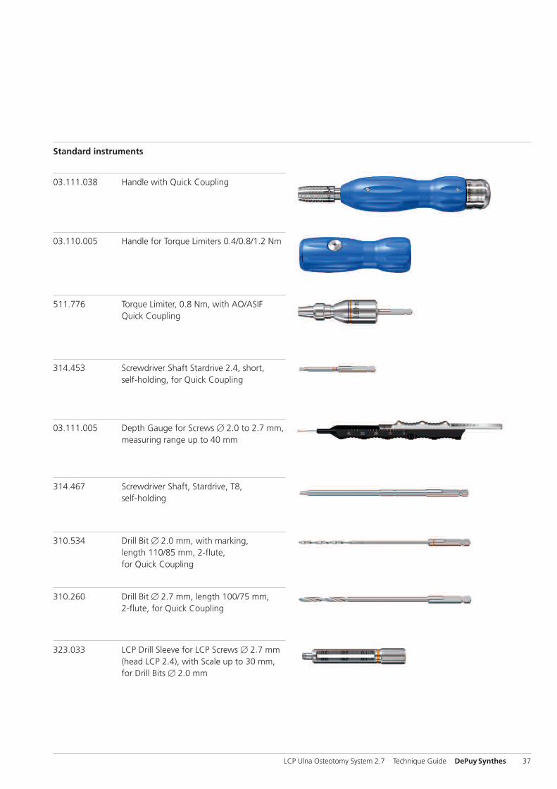
Standard instruments
03.111.005 Depth Gauge for Screws � 2.0 to 2.7 mm,measuring range up to 40 mm
314.467 Screwdriver Shaft, Stardrive, T8,self-holding
310.534 Drill Bit � 2.0 mm, with marking, length 110/85 mm, 2-flute, for Quick Coupling
310.260 Drill Bit � 2.7 mm, length 100/75 mm,2-flute, for Quick Coupling
323.033 LCP Drill Sleeve for LCP Screws � 2.7 mm(head LCP 2.4), with Scale up to 30 mm,for Drill Bits � 2.0 mm
03.110.005 Handle for Torque Limiters 0.4/0.8/1.2 Nm
511.776 Torque Limiter, 0.8 Nm, with AO/ASIFQuick Coupling
314.453 Screwdriver Shaft Stardrive 2.4, short,self-holding, for Quick Coupling
03.111.038 Handle with Quick Coupling

Instruments
38 DePuySynthes LCP Ulna Osteotomy System 2.7 Technique Guide
312.240 Double Drill Guide 2.7/2.0
311.260 Tap for Cortex Screws � 2.7 mm,length 100/33 mm
03.111.906 Tap for Locking Screws � 2.7 mm,length 100/33 mm
399.087 Holding Forceps with Ball, soft lock, length 156 mm
323.260 Universal Drill Guide 2.7
Optional instruments
399.082 Reduction Forceps, toothed, soft lock,length 146 mm
399.071 Reduction Forceps with Points, soft lock,length 126 mm
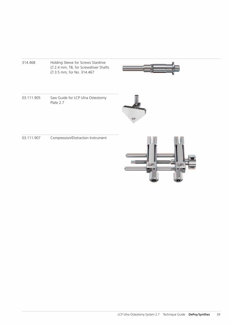
314.468 Holding Sleeve for Screws Stardrive� 2.4 mm, T8, for Screwdriver Shafts� 3.5 mm, for No. 314.467
03.111.905 Saw Guide for LCP Ulna Osteotomy Plate 2.7
03.111.907 Compression/Distraction Instrument
LCP Ulna Osteotomy System 2.7 Technique Guide DePuySynthes 39


0123
Synthes GmbHEimattstrasse 34436 OberdorfSwitzerlandTel: +41 61 965 61 11Fax: +41 61 965 66 00www.depuysynthes.com
This publication is not intended for distribution in the USA.
All technique guides are available as PDF files atwww.synthes.com/lit ©
DePuy Synthes Traum
a, a division of Synthes GmbH
. 2014. All rights reserved.
036.001.130 AB DSEM/TRM/0514/0076 11/ 14