Embed Size (px)
Citation preview
YT-450 OPERATIONS MANUAL MANUAL REV A
PAGE 1
LDG YT-450 100-Watt Automatic Tuner for Yaesu
FT-450 and FT-950 Transceivers
LDG Electronics 1445 Parran Road
St. Leonard MD 20685-2903 USA
Phone: 410-586-2177
Fax: 410-586-8475
www.ldgelectronics.com
PAGE 2
Table Of Contents Introduction 3
Jumpstart, or “Real hams don’t read manuals!” 3
Specifications 4
An Important Word About Power Levels 5
Important Safety Warning 5
Getting to know your YT-450 6
Front Panel 6
Rear Panel 7
Installation 8
Compatible Transceivers 8
Interface Cable 8
FT-450 Installation: 9
FT-950 Installation 10
Finishing Up Installation 11
Operation 11
Power-up 11
Basic Tuning Operation 11
Toggle Bypass Mode: 12
Initiate a Memory Tune Cycle: 13
Force a Full Tune Cycle: 14
Status LED 15
Application Information 15
Mobile Operation 15
Tuning On The 60 Meter Band 16
MARS/CAP Coverage 16
Operation with a PC / CAT 16
Using Both Antenna Ports on the FT-950 16
Theory of Operation 17
The LDG YT-450 20
A Word About Tuning Etiquette 21
Care and Maintenance 21
Technical Support 21
Two-Year Transferrable Warranty 21
Out Of Warranty Service 22
Returning Your Product For Service 22
Product Feedback 22
PAGE 3
INTRODUCTION
LDG pioneered the automatic, wide-range switched-L tuner in 1995. From its laboratories in St. Leonard, Maryland, LDG continues to define the state of the art in this field with innovative automatic tuners and related products for every amateur need.
Congratulations on selecting the YT-450 100-watt automatic tuner for the Yaesu FT-450 and FT-950 transceivers. The YT-450 provides semi-automatic antenna tuning across the entire HF spectrum plus 6 meters, at power levels up to 125 watts. It will tune dipoles, verticals, Yagis, or virtually any coax-fed antenna. It will match an amazing range of antennas and impedances, far greater than some other tuners you may have considered, including the built-in tuners on many radios.
The YT-450 is similar to previous LDG tuners, but is specially engineered to integrate with your Yaesu FT-450 or FT-950 HF radio. The YT-450 connects to the CAT (Computer Automated Transceiver) port on the back of the radio. The CAT interface allows an external device such as a PC or the YT-450 to control the FT-450/950 by sending it serial commands. The YT-450 takes advantage of this interface to simplify the tuning process -- one button push is all that is needed in order to switch the radio to AM mode, reduce output power, transmit a carrier, measure the transmit frequency, and then restore the radio to its previous mode and power level! Additionally, the YT-450 also draws power directly from the radio, so no extra cable is needed.
JUMPSTART, OR “REAL HAMS DON’T READ MANUALS!”
Ok, but at least read this one section before operating the YT-450:
Turn off power to your FT-450/950 radio.
Connect the antenna jack on the transceiver to the “TX” jack on the YT-450, using a 50 ohm coax cable jumper.
Connect the 50 ohm coax antenna feedline to the “ANT” jack on the YT-450.
Connect the 8-pin mini-DIN plug on the supplied radio interface cable to the “TUNER” port on the back of your FT-450/950. The YT-450 draws 12V power from the radio via this jack.
Connect the DB-9 plug on that same end of the radio interface cable to the “CAT” port on the back of your FT-450/950.
Connect the DC coax plug on the other end of the radio interface cable to the “Power” jack on the rear of the YT-450.
Connect the remaining DB-9 plug to the DB-9 jack marked “Radio” on the rear of the YT-450.
Using the radio’s menu system, set the CAT RATE to 38,400 baud, set the CAT TOT to 100, and set CAT RTS to “Enable”†.
Select the desired operating frequency and mode.
Push and hold the TUNE button on the front of the YT-450 for one second (until the Tuning LED comes on), then release. The transceiver automatically switches to AM mode, and keys up
† Be sure you have also set up the AM Carrier level to 25 watts, as per your FT-950 instruction manual, if using an FT-950 radio.
PAGE 4
with a minimal amount of power, and the YT-450 begins a tuning cycle. At the end of the tuning cycle, the original mode and power level is restored.
Wait for the tuning cycle to end; you’re now ready to operate!
SPECIFICATIONS
• 1 to 125 watts SSB and CW peak power, 100 watts on 6 meters, and 30 watts on PSK and digital modes.
• Latching relays for ultra-low power operation.
• 2,000 memories for instantaneous frequency and band changing.
• Power: 12V power supplied directly from the radio.
• Designed specifically for the Yaesu FT-450 and FT-950 HF transceivers.
• Pass-thru CAT port allows YT-450 to control the FT-xxx over the CAT bus while still allowing a host PC to also control the radio.
• Pass-thru CAT port waits for idle CAT activity before controlling the transceiver.
• 1.8 to 54.0 MHz coverage. Frequency for memory storage is read from the radio via CAT.
• Tunes 4 to 800 ohm loads (16 to 150 on 6M), 16 to 3200 ohms with optional 4:1 Balun.
• For Dipoles, Verticals, Vees, Beams or any Coax Fed Antenna.
• IC-450 Interface cable included.
• Optional external Balun allows tuning of random length, long wire or ladder line fed antennas. See web site for details.
• Dimensions: 7.25”L x 7.75”W x 2.25”H.
• Weight: 1 pound 8 ounces
PAGE 5
AN IMPORTANT WORD ABOUT POWER LEVELS
The YT-450 is rated at 125 watts maximum power input at most. Many ham transmitters and transceivers, and virtually all amplifiers, output well over 125 watts. Power levels that significantly exceed specifications will definitely damage or destroy your YT-450. If your tuner fails during overload, it could also damage your transmitter or transceiver. Be sure to observe the specified power limitations.
IMPORTANT SAFETY WARNING
Never install antennas or transmission lines over or near power lines. You can be seriously injured or killed if any part of the antenna, support or transmission line touches a power line. Always follow this antenna safety rule: the distance to the nearest power line should be at least twice the length of the longest antenna, transmission line or support dimension.
PAGE 6
GETTING TO KNOW YOUR YT-450
Your YT-450 is a quality, precision instrument that will give you many years of outstanding service; take a few minutes to get to know it.
The YT-450 is designed specifically for use with the FT-450 and FT-950 radios. Tuning is performed when the Tune button is pushed on the front of the YT-450 and held for one second. The tuner can be placed in bypass mode by pressing the Tune button momentarily.
The YT-450 is powered via the supplied DC coax plug. The YT-450 automatically powers up at the start of a tuning cycle, and goes into an ultra-low-power sleep mode when tuning is complete. The latching relays hold the tuned configuration indefinitely, even when DC power is completely removed. Tuning memories are stored in FLASH memory.
The YT-450 has 2,000 frequency memories. When tuning on or near a previously tuned frequency, the YT-450 uses “Memory Tune” to recall the previous tuning parameters in a fraction of a second. If no memorized settings are available, the tuner runs a full tuning cycle, storing the parameters for memory recall on subsequent tuning cycles on that frequency. In this manner, the YT-450 “learns” as it is used, adapting to the bands and frequencies as it goes.
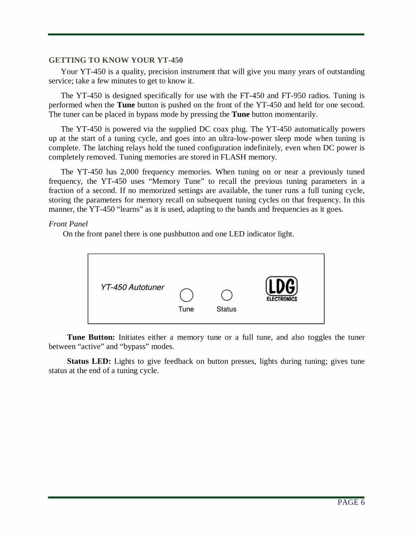
Front Panel On the front panel there is one pushbutton and one LED indicator light.
Tune Button: Initiates either a memory tune or a full tune, and also toggles the tuner between “active” and “bypass” modes.
Status LED: Lights to give feedback on button presses, lights during tuning; gives tune status at the end of a tuning cycle.
PAGE 7
Rear Panel
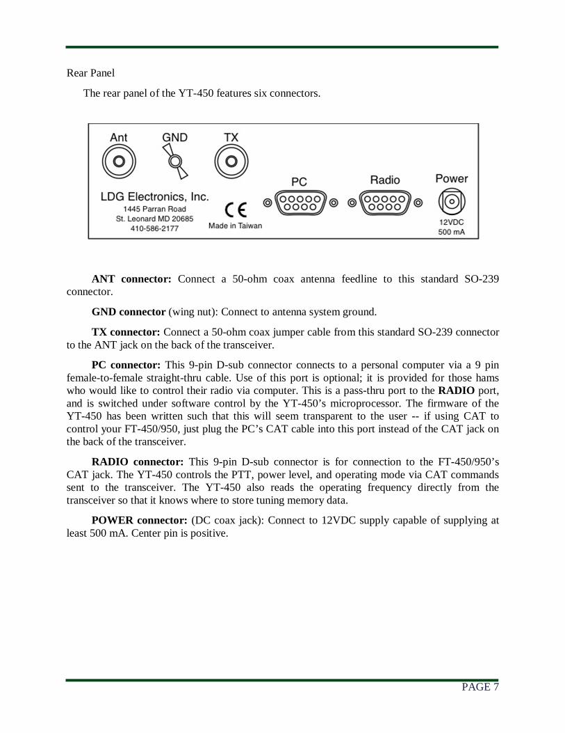
The rear panel of the YT-450 features six connectors.
ANT connector: Connect a 50-ohm coax antenna feedline to this standard SO-239 connector.
GND connector (wing nut): Connect to antenna system ground.
TX connector: Connect a 50-ohm coax jumper cable from this standard SO-239 connector to the ANT jack on the back of the transceiver.
PC connector: This 9-pin D-sub connector connects to a personal computer via a 9 pin female-to-female straight-thru cable. Use of this port is optional; it is provided for those hams who would like to control their radio via computer. This is a pass-thru port to the RADIO port, and is switched under software control by the YT-450’s microprocessor. The firmware of the YT-450 has been written such that this will seem transparent to the user -- if using CAT to control your FT-450/950, just plug the PC’s CAT cable into this port instead of the CAT jack on the back of the transceiver.
RADIO connector: This 9-pin D-sub connector is for connection to the FT-450/950’s CAT jack. The YT-450 controls the PTT, power level, and operating mode via CAT commands sent to the transceiver. The YT-450 also reads the operating frequency directly from the transceiver so that it knows where to store tuning memory data.
POWER connector: (DC coax jack): Connect to 12VDC supply capable of supplying at least 500 mA. Center pin is positive.
PAGE 8
INSTALLATION
The YT-450 tuner is designed for indoor operation only; it is not water resistant. If you use it outdoors (Field Day, for example), you must protect it from the rain. The YT-450 is designed for use with coax-fed antennas. If use with longwires or ladder-line-fed antennas is desired, an external balun is required. The LDG RBA-4:1 or RBA-1:1 is ideal, depending on the antenna and transmission line used.
Always turn your radio off before plugging or unplugging anything. The radio may be damaged if cables are connected or disconnected while the power is on.
Compatible Transceivers The YT-450 is designed to be used ONLY with the following Yaesu 100 watt transceivers:
FT-450
FT-950
WARNING: Do not attempt to use the YT-450 with any other transceivers, even if the CAT plug fits. At best, the YT-450 simply won’t work with these radios. At worst, it could cause damage to the YT-450, the radio, or both.
It is possible that more Yaesu transceivers will be added to this list as Yaesu releases new models. Be sure to check the LDG website for additional information.
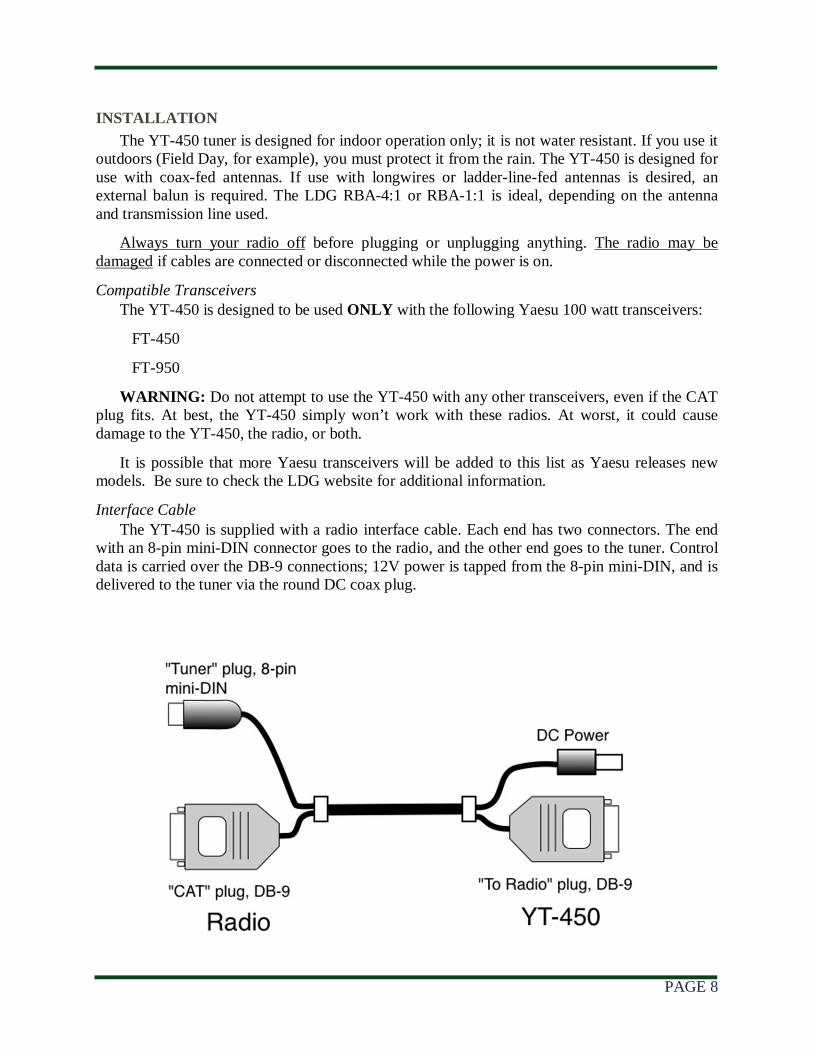
Interface Cable The YT-450 is supplied with a radio interface cable. Each end has two connectors. The end
with an 8-pin mini-DIN connector goes to the radio, and the other end goes to the tuner. Control data is carried over the DB-9 connections; 12V power is tapped from the 8-pin mini-DIN, and is delivered to the tuner via the round DC coax plug.
PAGE 9
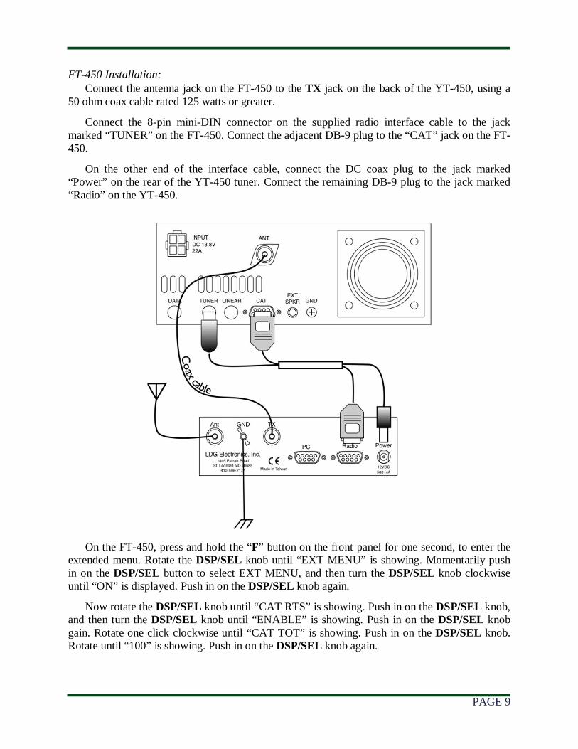
FT-450 Installation: Connect the antenna jack on the FT-450 to the TX jack on the back of the YT-450, using a
50 ohm coax cable rated 125 watts or greater.
Connect the 8-pin mini-DIN connector on the supplied radio interface cable to the jack marked “TUNER” on the FT-450. Connect the adjacent DB-9 plug to the “CAT” jack on the FT-450.
On the other end of the interface cable, connect the DC coax plug to the jack marked “Power” on the rear of the YT-450 tuner. Connect the remaining DB-9 plug to the jack marked “Radio” on the YT-450.
On the FT-450, press and hold the “F” button on the front panel for one second, to enter the extended menu. Rotate the DSP/SEL knob until “EXT MENU” is showing. Momentarily push in on the DSP/SEL button to select EXT MENU, and then turn the DSP/SEL knob clockwise until “ON” is displayed. Push in on the DSP/SEL knob again.
Now rotate the DSP/SEL knob until “CAT RTS” is showing. Push in on the DSP/SEL knob, and then turn the DSP/SEL knob until “ENABLE” is showing. Push in on the DSP/SEL knob gain. Rotate one click clockwise until “CAT TOT” is showing. Push in on the DSP/SEL knob. Rotate until “100” is showing. Push in on the DSP/SEL knob again.
PAGE 10
Rotate the DSP/SEL knob one click clockwise until “CATRATE” is showing. Push in on the DSP/SEL knob. Rotate the DSP/SEL knob until “38400” is showing. Push in on the DSP/SEL knob one final time. Now push and hold the “F” button to return to normal operation.
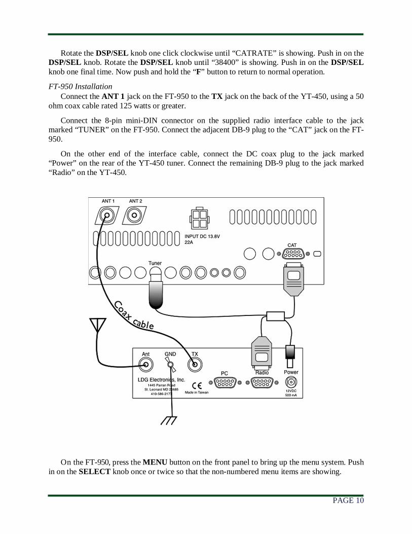
FT-950 Installation Connect the ANT 1 jack on the FT-950 to the TX jack on the back of the YT-450, using a 50
ohm coax cable rated 125 watts or greater.
Connect the 8-pin mini-DIN connector on the supplied radio interface cable to the jack marked “TUNER” on the FT-950. Connect the adjacent DB-9 plug to the “CAT” jack on the FT-950.
On the other end of the interface cable, connect the DC coax plug to the jack marked “Power” on the rear of the YT-450 tuner. Connect the remaining DB-9 plug to the jack marked “Radio” on the YT-450.
On the FT-950, press the MENU button on the front panel to bring up the menu system. Push in on the SELECT knob once or twice so that the non-numbered menu items are showing.

PAGE 11
Rotate the SELECT knob until the menu “CAT BPS” is showing. You may have to rotate for a while; the FT-950 has a LOT of menu options.
With “CAT BPS” showing on the screen, rotate the CLAR/VFO-B knob fully clockwise until “384H” is showing. Rotate the SELECT knob one click clockwise until “CAT TOT” is showing. Now rotate the CLAR/VFO-B dial until “100” is showing.
Rotate the SELECT knob one more click clockwise, until “CAT RTS” is displayed. Now rotate the CLAR/VFO-B knob until “On” is displayed. Finally, press and hold the MENU button for 2 seconds so that these new settings take effect.
Also, be sure to set your FT-950’s AM CAR menu per the FT-950 instruction manual, to select 25 watts as the AM carrier level.
Finishing Up Installation Connect a 50-ohm coax feedline to the jack marked ANT on the rear of the YT-450, and
connect this to the antenna system.
If it is desired to operate the FT-450 / 950 via computer control, connect a straight-thru 9-pin female-to-female cable (not supplied) to the jack on the YT-450 marked “PC”. The YT-450 will automatically feed through any CAT commands coming in over this port to the transceiver and vice versa. Note that any software used to control the transceiver will have to be set for 38,400 baud while connected through the YT-450.
Grounding the YT-450 tuner will enhance its performance and safety. LDG recommends that you connect your tuner to a suitable ground; a common ground rod connected to buried radials is preferred, but a single ground rod, a cold water pipe, or the screw that holds the cover on an AC outlet can provide a serviceable ground. LDG strongly recommends the use of a properly installed, high quality lightning arrestor on all antenna cables.
OPERATION
Power-up The YT-450 is powered by the transceiver. When the YT-450 is first powered on, the Status
LED will blink once to indicate it is functioning properly. The first time the TUNE button is pressed, the YT-450 checks the connection to the transceiver. If this check fails, the Status LED will blink continuously.
Possible causes for failure to detect the radio properly are an improperly seated CAT cable, a damaged CAT cable, incorrectly selected CAT baud rate, or plugging the CAT cable into a radio other than an FT-450 or FT-950. If checking all of these things does not correct the situation, try turning the radio and tuner off and back on again.
Basic Tuning Operation The YT-450 is operated from the front panel TUNE button on the YT-450. Two types of
tuning cycles are available; a memory tuning cycle and a full tuning cycle.
The memory tuning cycle attempts to tune quickly based on having previously tuned on the present frequency selection. If the tuner previously was successful in tuning on the currently selected frequency, the settings for that match will be loaded into the tuner relays, and checked to see that an acceptable SWR match is found.
PAGE 12
A full tuning cycle “starts from scratch” and begins a fixed tuning sequence where the YT-450 rapidly tries varying combinations of inductance and capacitance values, and then zeroes-in on the best match possible. When the tuning cycle is complete, if an acceptable match was found, the inductance and capacitance settings are saved in a memory associated with the selected frequency, so that they may be recalled quickly in the future via a memory tuning cycle.
In this manner, the YT-450 “learns”; the longer you use it, the more closely it adapts itself to the bands and frequencies used. Most users will probably use memory tuning most of the time; it takes advantage of any saved tuning settings, but automatically defaults to a full tuning cycle if no stored data is available.
In both cases, at the end of the tuning cycle, the carrier is held for 1.5 seconds after tuning is complete, so that the final SWR may be read on the transceiver’s internal SWR meter or another inline SWR meter, and the front panel LED will indicate the status of the tuning cycle.
The tuner may also be placed in “bypass” mode where it is electrically removed from the antenna system.
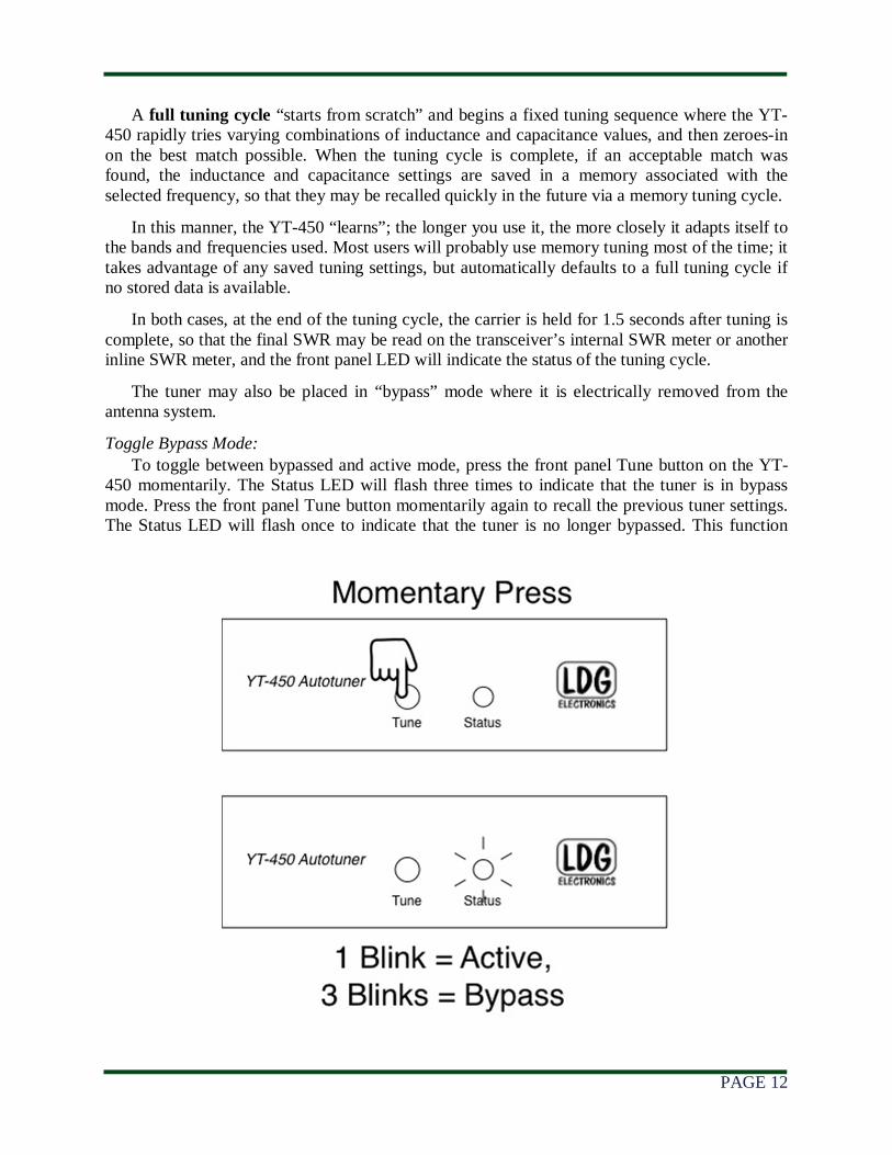
Toggle Bypass Mode: To toggle between bypassed and active mode, press the front panel Tune button on the YT-
450 momentarily. The Status LED will flash three times to indicate that the tuner is in bypass mode. Press the front panel Tune button momentarily again to recall the previous tuner settings. The Status LED will flash once to indicate that the tuner is no longer bypassed. This function
PAGE 13
may be useful if you wish to compare antenna performance with and without the benefit of the tuner’s matching network.
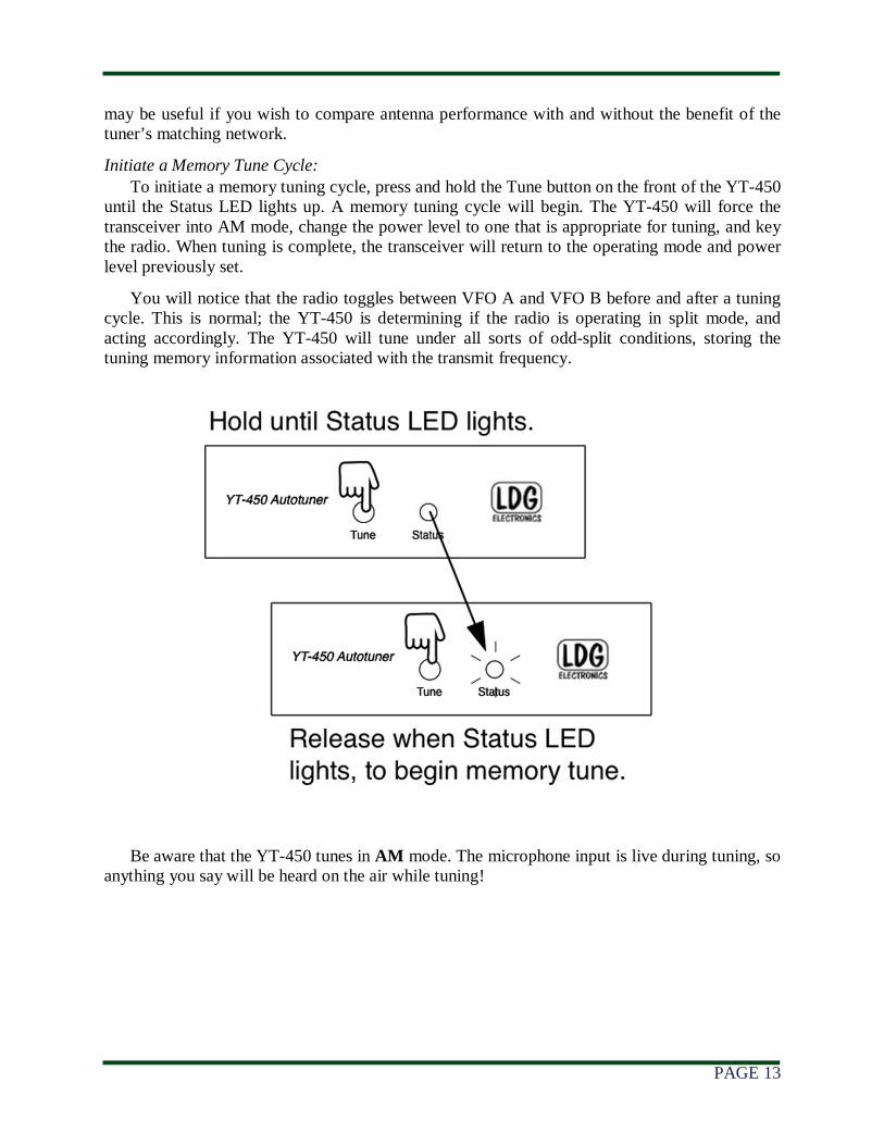
Initiate a Memory Tune Cycle: To initiate a memory tuning cycle, press and hold the Tune button on the front of the YT-450
until the Status LED lights up. A memory tuning cycle will begin. The YT-450 will force the transceiver into AM mode, change the power level to one that is appropriate for tuning, and key the radio. When tuning is complete, the transceiver will return to the operating mode and power level previously set.
You will notice that the radio toggles between VFO A and VFO B before and after a tuning cycle. This is normal; the YT-450 is determining if the radio is operating in split mode, and acting accordingly. The YT-450 will tune under all sorts of odd-split conditions, storing the tuning memory information associated with the transmit frequency.
Be aware that the YT-450 tunes in AM mode. The microphone input is live during tuning, so anything you say will be heard on the air while tuning!
PAGE 14
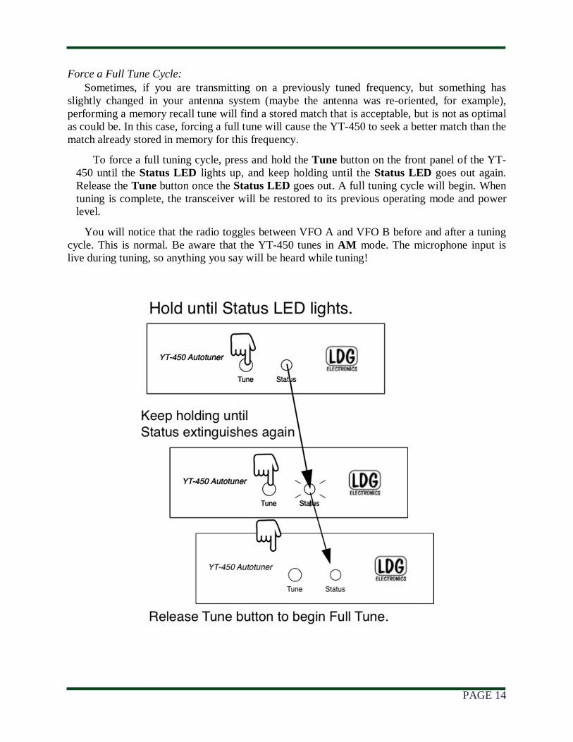
Force a Full Tune Cycle: Sometimes, if you are transmitting on a previously tuned frequency, but something has
slightly changed in your antenna system (maybe the antenna was re-oriented, for example), performing a memory recall tune will find a stored match that is acceptable, but is not as optimal as could be. In this case, forcing a full tune will cause the YT-450 to seek a better match than the match already stored in memory for this frequency.
To force a full tuning cycle, press and hold the Tune button on the front panel of the YT-450 until the Status LED lights up, and keep holding until the Status LED goes out again. Release the Tune button once the Status LED goes out. A full tuning cycle will begin. When tuning is complete, the transceiver will be restored to its previous operating mode and power level.
You will notice that the radio toggles between VFO A and VFO B before and after a tuning cycle. This is normal. Be aware that the YT-450 tunes in AM mode. The microphone input is live during tuning, so anything you say will be heard while tuning!
PAGE 15
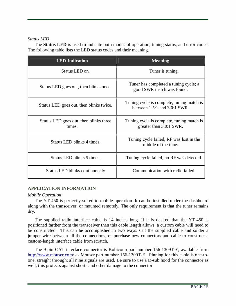
Status LED The Status LED is used to indicate both modes of operation, tuning status, and error codes.
The following table lists the LED status codes and their meaning.
LED Indication Meaning
Status LED on. Tuner is tuning.
Status LED goes out, then blinks once. Tuner has completed a tuning cycle; a
good SWR match was found.
Status LED goes out, then blinks twice. Tuning cycle is complete, tuning match is
between 1.5:1 and 3.0:1 SWR.
Status LED goes out, then blinks three times.
Tuning cycle is complete, tuning match is greater than 3.0:1 SWR.
Status LED blinks 4 times. Tuning cycle failed, RF was lost in the
middle of the tune.
Status LED blinks 5 times. Tuning cycle failed, no RF was detected.
Status LED blinks continuously Communication with radio failed.
APPLICATION INFORMATION
Mobile Operation The YT-450 is perfectly suited to mobile operation. It can be installed under the dashboard
along with the transceiver, or mounted remotely. The only requirement is that the tuner remains dry.
The supplied radio interface cable is 14 inches long. If it is desired that the YT-450 is positioned farther from the transceiver than this cable length allows, a custom cable will need to be constructed. This can be accomplished in two ways: Cut the supplied cable and solder a jumper wire between all the connections, or purchase new connectors and cable to construct a custom-length interface cable from scratch.
The 9-pin CAT interface connector is Kobiconn part number 156-1309T-E, available from http://www.mouser.com/ as Mouser part number 156-1309T-E. Pinning for this cable is one-to-one, straight through; all nine signals are used. Be sure to use a D-sub hood for the connector as well; this protects against shorts and other damage to the connector.
PAGE 16
Tuning On The 60 Meter Band The YT-450 tunes in AM mode, but, in the United States, the FCC requires that only SSB
transmissions can be made in the 60 meter band. To that end, the FT-450 and FT-950 radios will not switch to AM mode during tuning, but will remain in SSB mode. If no audio signal is present during SSB transmission on 60 meters, then no RF will be generated, and the YT-450 will blink a “No RF Was Detected” error.
In order to tune on the 60 meter band, then, speak into the microphone while tuning. It will suffice to say “Ahh” for a few seconds while tuning. Be sure to identify your communications, as is required by FCC rules.
MARS/CAP Coverage The YT-450 provides continuous tuning coverage over its specified range; not just in the ham
bands. This makes it useful for MARS or CAP operation, or any other legal HF operation.
Operation with a PC / CAT Although the YT-450 uses the transceiver’s CAT port for tuning control, the YT-450 is
designed to allow the user to continue to use the CAT interface with the transceiver for PC control, also.
If PC control of the radio is desired, simply hook a 9 pin straight thru female-to-female cable to the PC jack on the rear of the YT-450, and connect to the PC’s serial port.
Any rig control software on the computer must be set to use the 38,400 baud rate, as this is the communication rate used by the YT-450 for controlling the radio.
The YT-450 monitors the Computer port for activity before beginning any tuning cycle. Only when the CAT line is idle for a period of time will the YT-450 take over control of the CAT line in order to perform a tuning cycle. When the tuning cycle is complete, control of the CAT interface is returned to the PC.
This procedure is completely automatic, and is transparent to the user. Simply hook up a PC, and use the rig control software as normal. Press the TUNE button on the YT-450 when tuning is desired. Some rig control software will detect that the radio is no longer communicating with the PC during tuning. This is normal, and communications with the PC will resume once the tuning cycle is complete.
Note: The YT-450 must be powered-on in order for its pass-through CAT port to function.
Using Both Antenna Ports on the FT-950 The FT-950 radio comes with two antenna ports, selectable via the ANT 1-2 button in the
upper left corner of the FT-950’s front panel. It is also possible to set up an “odd split” on the radio where transmission is done on one antenna, and reception on the other. Simply choose different antennas for VFO-A and VFO-B, and then enable split mode.
With a pair of YT-450 tuners, it is possible to use both antenna ports, and have one-button pushbutton tuning for each antenna. This is possible via “daisy-chaining” the CAT ports on the two YT-450 tuners. Just be sure to have the correct antenna selected on the radio when pushing the TUNE button on the YT-450 connected to that antenna port.
PAGE 17
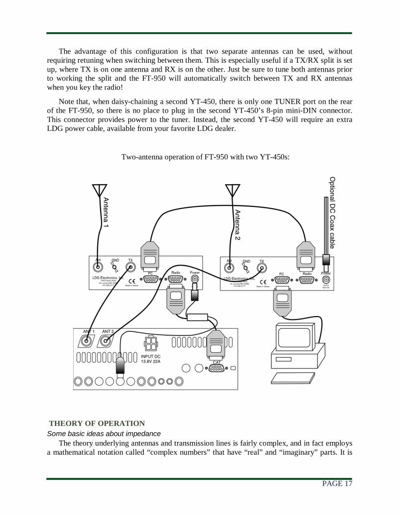
The advantage of this configuration is that two separate antennas can be used, without requiring retuning when switching between them. This is especially useful if a TX/RX split is set up, where TX is on one antenna and RX is on the other. Just be sure to tune both antennas prior to working the split and the FT-950 will automatically switch between TX and RX antennas when you key the radio!
Note that, when daisy-chaining a second YT-450, there is only one TUNER port on the rear of the FT-950, so there is no place to plug in the second YT-450’s 8-pin mini-DIN connector. This connector provides power to the tuner. Instead, the second YT-450 will require an extra LDG power cable, available from your favorite LDG dealer.
Two-antenna operation of FT-950 with two YT-450s:
THEORY OF OPERATION
Some basic ideas about impedance
The theory underlying antennas and transmission lines is fairly complex, and in fact employs a mathematical notation called “complex numbers” that have “real” and “imaginary” parts. It is
PAGE 18
beyond the scope of this manual to present a tutorial on this subject1, but a little background will help in understanding what the YT-450 is doing, and how it does it.
In simple DC circuits, the wire resists current flow, converting some of it into heat. The relationship between voltage, current, and resistance is described by the elegant and well-known “Ohm’s Law”, named for Georg Simon Ohm of Germany, who first discovered the principle in 1826. In RF circuits, an analogous but more complicated relationship exists.
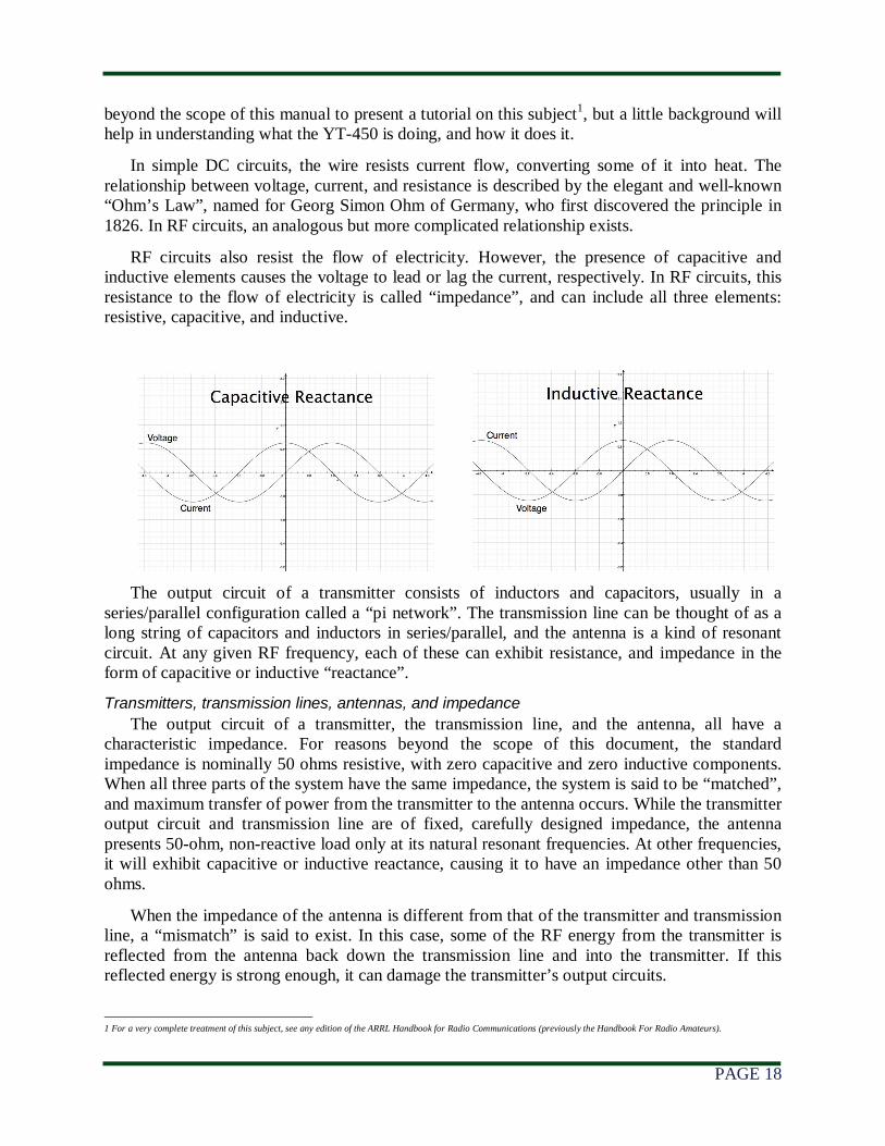
RF circuits also resist the flow of electricity. However, the presence of capacitive and inductive elements causes the voltage to lead or lag the current, respectively. In RF circuits, this resistance to the flow of electricity is called “impedance”, and can include all three elements: resistive, capacitive, and inductive.
The output circuit of a transmitter consists of inductors and capacitors, usually in a series/parallel configuration called a “pi network”. The transmission line can be thought of as a long string of capacitors and inductors in series/parallel, and the antenna is a kind of resonant circuit. At any given RF frequency, each of these can exhibit resistance, and impedance in the form of capacitive or inductive “reactance”.
Transmitters, transmission lines, antennas, and impedance
The output circuit of a transmitter, the transmission line, and the antenna, all have a characteristic impedance. For reasons beyond the scope of this document, the standard impedance is nominally 50 ohms resistive, with zero capacitive and zero inductive components. When all three parts of the system have the same impedance, the system is said to be “matched”, and maximum transfer of power from the transmitter to the antenna occurs. While the transmitter output circuit and transmission line are of fixed, carefully designed impedance, the antenna presents 50-ohm, non-reactive load only at its natural resonant frequencies. At other frequencies, it will exhibit capacitive or inductive reactance, causing it to have an impedance other than 50 ohms.
When the impedance of the antenna is different from that of the transmitter and transmission line, a “mismatch” is said to exist. In this case, some of the RF energy from the transmitter is reflected from the antenna back down the transmission line and into the transmitter. If this reflected energy is strong enough, it can damage the transmitter’s output circuits.
1 For a very complete treatment of this subject, see any edition of the ARRL Handbook for Radio Communications (previously the Handbook For Radio Amateurs).
PAGE 19
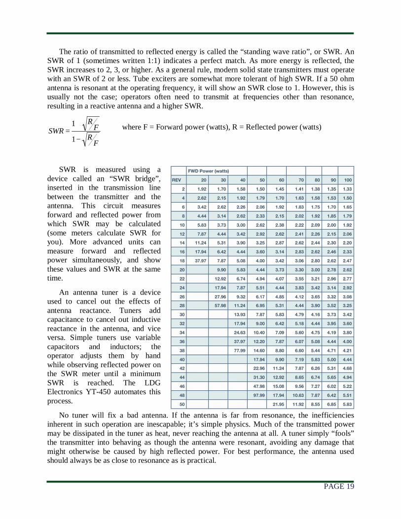
The ratio of transmitted to reflected energy is called the “standing wave ratio”, or SWR. An SWR of 1 (sometimes written 1:1) indicates a perfect match. As more energy is reflected, the SWR increases to 2, 3, or higher. As a general rule, modern solid state transmitters must operate with an SWR of 2 or less. Tube exciters are somewhat more tolerant of high SWR. If a 50 ohm antenna is resonant at the operating frequency, it will show an SWR close to 1. However, this is usually not the case; operators often need to transmit at frequencies other than resonance, resulting in a reactive antenna and a higher SWR.
where F = Forward power (watts), R = Reflected power (watts)
SWR is measured using a device called an “SWR bridge”, inserted in the transmission line between the transmitter and the antenna. This circuit measures forward and reflected power from which SWR may be calculated (some meters calculate SWR for you). More advanced units can measure forward and reflected power simultaneously, and show these values and SWR at the same time.
An antenna tuner is a device used to cancel out the effects of antenna reactance. Tuners add capacitance to cancel out inductive reactance in the antenna, and vice versa. Simple tuners use variable capacitors and inductors; the operator adjusts them by hand while observing reflected power on the SWR meter until a minimum SWR is reached. The LDG Electronics YT-450 automates this process.
No tuner will fix a bad antenna. If the antenna is far from resonance, the inefficiencies inherent in such operation are inescapable; it’s simple physics. Much of the transmitted power may be dissipated in the tuner as heat, never reaching the antenna at all. A tuner simply “fools” the transmitter into behaving as though the antenna were resonant, avoiding any damage that might otherwise be caused by high reflected power. For best performance, the antenna used should always be as close to resonance as is practical.
SWR =1+ R
F
1− RF
PAGE 20
THE LDG YT-450
In 1995, LDG Electronics pioneered a new type of automatic antenna tuner. The LDG design uses banks of fixed capacitors and inductors, switched in and out of the circuit by relays under microprocessor control. An additional relay switches between high and low impedance ranges. A built-in SWR sensor provides feedback; the microprocessor searches the capacitor and inductor banks, seeking the lowest possible SWR. The tuner is a “Switched L” network, consisting of series inductors and parallel capacitors. LDG chose the L network for its minimum number of parts and its ability to tune unbalanced loads, such as coax-fed dipoles, verticals, Yagis, and, in fact, virtually any coax-fed antenna.
The series inductors are switched in and out of the circuit, and the parallel capacitors are switched to ground under microprocessor control. The high/low impedance relay switches the capacitor bank either to the transmitter side of the inductor bank, or to the antenna side. This allows the YT-450 to handle loads that are either greater than or less than 50 ohms. All relays are sized to carry 125 watts continuously.
The SWR sensor is a variation of the Bruene circuit. This SWR measuring technique is used in most dual-meter and direct-reading SWR meters. Slight modifications were made to the circuit to provide voltages instead of currents for the analog-to-digital converters that provide signals proportional to the forward and reflected power levels. The single-lead primary through the center of the sensor transformer provides RF current sampling. Diodes rectify the sample and provide a DC voltage proportional to RF power. These two voltages are read by the ADCs in the microprocessor, and are used to compute SWR in real time.
The relays are powered by the 12VDC input provided by CAT interface cable. The relays are a latching type, and so they consume no current when not actively switching.
Although the microprocessor’s oscillator runs at 32 MHz, which allows the main tuning routine to execute in only a few milliseconds, the relays require several milliseconds of settling time for every combination of inductors and capacitors. Thus, it may take several seconds before all relay combinations are exhausted, in the case of a difficult tune.
The tuning routine uses an algorithm to minimize the number of tuner adjustments. The routine first de-energizes the high/low impedance relay if necessary, and then individually steps through the inductors to find a coarse match. With the best inductor selected, the tuner then steps through the individual capacitors to find the best coarse match. If no match is found, the routine repeats the coarse tuning with the high/low impedance relay energized. The routine then fine tunes the inductors and capacitors. The program checks LC combinations to see if a 1.5:1 or lower SWR can be obtained and stops when it finds a good match.
The microprocessor runs a fine tune routine just after the tuner finds a match of 1.5:1 or less. This fine tune routine now tries to tune the SWR as low as possible (not just to 1.5); it takes about half a second to run.
PAGE 21
A WORD ABOUT TUNING ETIQUETTE
Be sure to use a vacant frequency when tuning. With today’s crowded ham bands, this is often difficult. However, causing interference to other hams should be avoided as much as possible. The YT-450’s very short tuning cycle minimizes the impact of tuning transmissions.
CARE AND MAINTENANCE
The YT-450 tuner is essentially maintenance-free. Power limits in this manual should be strictly adhered to. The outer case may be cleaned as needed with a soft cloth slightly dampened with household cleaning solution. As with any modern electronic device, the YT-450 can be damaged by temperature extremes, water, impact, or static discharge. LDG strongly recommends the use of a good quality, properly installed lightning arrestor in the antenna lead.
TECHNICAL SUPPORT
The LDG customer support staff is ready to answer your product question by telephone and by e-mail. We know that you will enjoy your product even more knowing LDG is ready to answer your questions as the need arises.
LDG regularly updates on-line information so the best on-line support information is available all day and every day.
The LDG website provides links to product manuals, just in case you lose this one! When you are thinking about the purchase of other LDG products our website also has complete product specifications and photographs you can use to help make your purchase decision. Don’t forget the links to all of the quality LDG Dealers also ready to help you make that purchase decision.
TWO-YEAR TRANSFERRABLE WARRANTY
Your product is warranted against manufacturer defects in parts and labor for two full years from the date of purchase. This two-year warranty is also transferable. When you sell or give away your LDG product, give the new owner a copy of the original sales receipt and the two-year warranty goes with the new owner.
There is no need to complete a warranty card or to register an LDG product. Your product receipt establishes eligibility for warranty service, so save that receipt. Send your receipt with the product whenever you send your product to LDG for repair. Products sent to LDG without a receipt are considered requests for out-of-warranty repair.
LDG does not warranty against product damage or abuse. This means that a product failure, as determined by LDG, to be caused by the customer or by other natural calamity (e.g. lightning) is not covered under the two-year warranty. Damage can be caused by failure to heed the product’s published limitations and specifications or by not following good Amateur practice.
PAGE 22
OUT OF WARRANTY SERVICE
If a product fails after the warranty period, LDG wants to help you get it fixed. Send the product to us for repair any time you like. We will determine what needs to be done and based on your instructions, either contact you with an estimate or fix it and contact you with a request to pay any repair charges. Please contact LDG if you have any questions before you send us an out-of-warranty product for repair.
RETURNING YOUR PRODUCT FOR SERVICE
Returning a product to LDG is easy. We do not require a return merchandise authorization, and there is no need to contact LDG to return your product. Visit the LDG web site and download the LDG Product Repair Form. On the Repair Form tell the LDG technicians exactly what happened or didn’t happen and why you believe the product needs servicing. The technician attempts to duplicate the problem(s) you had based on how well you describe it so take the time to be accurate and complete.
Ask your shipper for a tracking number or a delivery verification receipt. This way you know the product arrived safely at LDG. Be sure to give us your email address so our shipper can alert you online when your product is en-route back to you. Please be assured that our staff makes every effort to complete repairs ahead of our published wait time. Your patience is appreciated.
Repairs can take six to eight weeks, but are usually faster. The most recent information on returning products for service is found on the LDG website under Support, then Tech Support. Send your carefully packaged unit with the Repair Form to:
LDG Electronics, Inc.
Attn: Repair Department
1445 Parran Rd
St. Leonard, MD 20685
PRODUCT FEEDBACK
We encourage product feedback! Tell us what you really think of your LDG product. In a card, letter, or email (preferred) tell us how you used the product and how well it worked in your application. Send along a photo or even a schematic or drawing to illustrate your narrative. We like to share your comments with our staff, our dealers, and even other customers at the LDG website:
http://www.ldgelectronics.com/


![Untitled-1 [] · YT.. 0300 YT.. 0300 YT.. 0300 YT.. 0300. Title: Untitled-1 Author: Eyup Created Date: 4/4/2016 11:28:30 AM](https://img.pdfslide.net/doc/110x75/5f24e2450a7e2c6cc2663645/untitled-1-yt-0300-yt-0300-yt-0300-yt-0300-title-untitled-1-author.jpg)