Embed Size (px)
Citation preview
SMART POSITIONER PRODUCT MANUAL YT-3400 / 3450 / 3410 SERIES
YT-3400
YT-3450
YT-3410
Rotork YTC Limited
VERSION 1.10
Smart Positioner YT-3400 / 3450 / 3410 series Product manual
Ver. 1.10 2
Contents 1. Introduction .................................................................................................................................................5
1.1 General Information for the users .........................................................................................................5
1.2 Manufacturer Warranty .........................................................................................................................5
1.3 Explosion Proof Warning & Specific Conditions of Use .......................................................................6
2. Product Description ...................................................................................................................................7
2.1 General .................................................................................................................................................7
2.2 Main Features and Functions ...............................................................................................................7
2.3 Label Description ..................................................................................................................................8
2.4 Product Code ..................................................................................................................................... 13
2.4.1 YT-3400 / 3450 series follows suffix symbols as follows. .............................................................. 13
2.4.2 YT-3410 series follows suffix symbols as follows. ......................................................................... 14
2.5 Product Specification ......................................................................................................................... 15
2.6 Certifications ...................................................................................................................................... 16
2.7 Parts and Assembly ........................................................................................................................... 18
2.8 Product Dimension ............................................................................................................................ 20
2.8.1 YT-3400 ......................................................................................................................................... 20
2.8.2 YT-3450 ......................................................................................................................................... 21
2.8.3 YT-3410 ......................................................................................................................................... 22
3. Installation ................................................................................................................................................ 23
3.1 Safety ................................................................................................................................................. 23
3.2 Tools for installation ........................................................................................................................... 24
3.3 Linear positioner Installation .............................................................................................................. 24
3.3.1 Linear positioner Installation .......................................................................................................... 24
3.3.1.1 Safety ..................................................................................................................................... 25
3.3.1.2 Standard lever type positioner Installation Steps ................................................................... 25
3.3.2 YT-3410L Installation of Adapter lever type (on tubeless actuator) .............................................. 30
3.3.2.1 Safety ..................................................................................................................................... 30
3.3.2.2 Adapter lever type positioner Installation Steps ..................................................................... 31
3.4 Rotary positioner Installation ............................................................................................................. 33
3.4.1 YT-3400R / 3450R Components ................................................................................................... 33
3.4.2 YT-3410R Components ................................................................................................................. 34
3.4.3 Rotary Bracket Information ............................................................................................................ 35
3.4.4 Rotary positioner Installation Steps ............................................................................................... 37
4. Connection - Air ....................................................................................................................................... 40
4.1 Safety ................................................................................................................................................. 40
4.2 Supply Pressure Condition ................................................................................................................ 40
4.3 Piping Condition ................................................................................................................................. 40
4.4 Connection – Piping with actuator ..................................................................................................... 41
4.4.1 Single acting actuator .................................................................................................................... 41
Smart Positioner YT-3400 / 3450 / 3410 series Product manual
Ver. 1.10 3
4.4.2 Double acting actuator ................................................................................................................... 42
5. Connection – Power ................................................................................................................................ 43
5.1 Safety ................................................................................................................................................. 43
5.2 Terminal overview .............................................................................................................................. 45
5.2.1 Input Signal Terminal ..................................................................................................................... 46
5.2.2 Feedback Signal Terminal ............................................................................................................. 47
5.2.3 Limit Switch Terminal ..................................................................................................................... 47
5.2.4 Ground ........................................................................................................................................... 48
6. Adjustments ............................................................................................................................................. 49
6.1 Limit Switch Adjustment ..................................................................................................................... 49
6.2 A/M switch adjustment ....................................................................................................................... 50
6.3 Variable Orifice Adjustment (except YT-3410) .................................................................................. 51
7. Auto Calibration and PCB Operation ..................................................................................................... 52
7.1 Warning .............................................................................................................................................. 52
7.2 Button Description ............................................................................................................................. 52
7.3 Run Mode (RUN) ............................................................................................................................... 52
7.4 Auto Calibration mode (AUTO CAL) .................................................................................................. 53
7.4.1 AUTO1 Calibration (AUTO1) ......................................................................................................... 53
7.4.2 AUTO2 Calibration (AUTO2) ......................................................................................................... 54
7.4.3 AUTO 3 Calibration (AUTO 3) ....................................................................................................... 54
7.4.4 AUTO HF Calibration (AUTO HF).................................................................................................. 54
7.5 Manual Mode (MANUAL) ................................................................................................................... 55
7.6 Parameter Mode (PARAM) ................................................................................................................ 55
7.6.1 Dead-Zone (dEAdZONE, %) ......................................................................................................... 56
7.6.2 P Value (KP) .................................................................................................................................. 56
7.6.3 I Value (KI) ..................................................................................................................................... 57
7.6.4 D Value (Kd) .................................................................................................................................. 57
7.6.5 P_ (KP_), I_(KI_), D_ (Kd_) Values ............................................................................................... 57
7.6.6 KF Up Value (KFUP) ..................................................................................................................... 58
7.6.7 KF Down Value (KFdN) ................................................................................................................. 58
7.6.8 Control mode (CTRL) ...................................................................................................................... 59
7.7 Hand Calibration Mode (HAND CAL) ................................................................................................ 60
7.7.1 Zero-Point (PV ZERO) and End-Point (PV END) for Valves ......................................................... 60
7.7.2 Zero-Point (TR ZERO) and End-Point (TR END) for Transmitter ................................................. 61
7.7.3 Normal / Reverse Feedback Signal (TR NORM / REVS) .............................................................. 62
7.7.4 Normal / Reverse HART Signal (HT NORM / REVS) .................................................................... 63
7.8 Valve Mode (VALVE) ......................................................................................................................... 64
7.8.1 Acting Adjustment (ACT RA / dA) .................................................................................................. 64
7.8.2 Valve flow Characteristic Adjustment (CHAR) ............................................................................... 65
7.8.3 User defining flow Characteristics (USER SET) ............................................................................ 66
Smart Positioner YT-3400 / 3450 / 3410 series Product manual
Ver. 1.10 4
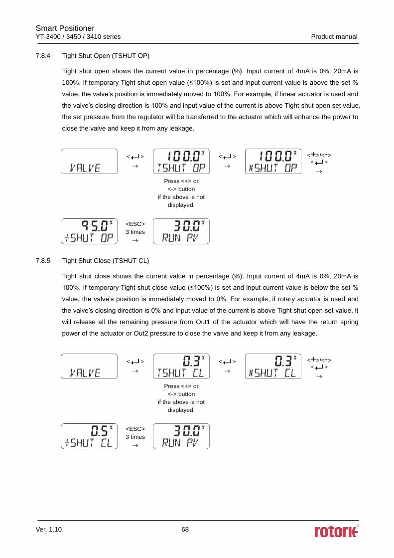
7.8.4 Tight Shut Open (TSHUT OP) ....................................................................................................... 68
7.8.5 Tight Shut Close (TSHUT CL) ....................................................................................................... 68
7.8.6 Split Range Mode (SPLIT) ............................................................................................................. 69
7.8.7 Custom Zero Setting Mode of Split Range (CST ZERO) .............................................................. 69
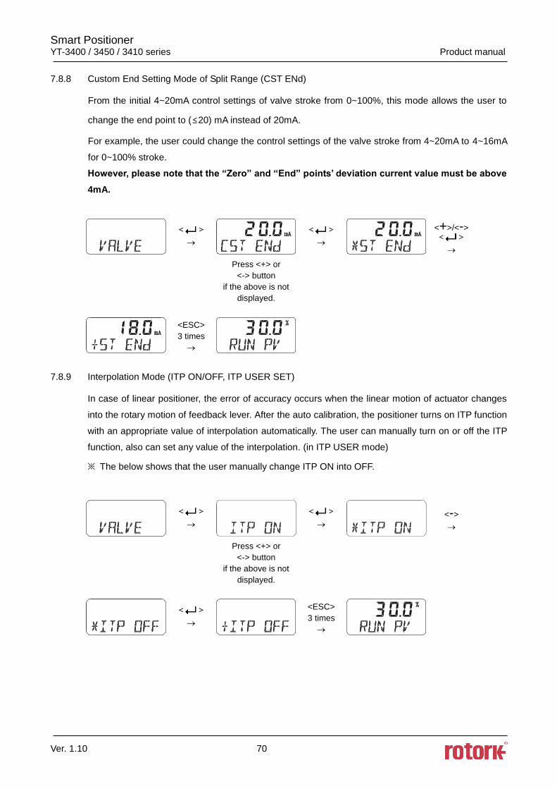
7.8.8 Custom End Setting Mode of Split Range (CST ENd) .................................................................. 70
7.8.9 Interpolation Mode (ITP ON/OFF, ITP USER SET) ....................................................................... 70
7.8.10 Acting Type (SINGLE / dOUBLE) .............................................................................................. 71
7.8.11 Lever Type (STd / AdT) ............................................................................................................. 71
7.9 Diagnostic (dIAGNO) ......................................................................................................................... 72
7.9.1 PST Introduction ............................................................................................................................ 72
7.9.2 PST Mode ...................................................................................................................................... 73
7.9.3 PST CFG ....................................................................................................................................... 73
7.9.3.1 START PO ............................................................................................................................. 74
7.9.3.2 TARGET 1 .............................................................................................................................. 74
7.9.3.3 TARGET 2 .............................................................................................................................. 75
7.9.3.4 INTERVAL .............................................................................................................................. 75
7.9.3.5 TOL ........................................................................................................................................ 76
7.9.3.6 LIMIT TM ................................................................................................................................ 76
7.9.3.7 LATENCY ............................................................................................................................... 77
7.9.4 PST RSLT ...................................................................................................................................... 77
7.10 View Mode (VIEW) ............................................................................................................................ 78
8. Error and Warning Code ......................................................................................................................... 80
8.1 Error code which is displayed during Auto calibration ....................................................................... 80
8.2 Error code which is displayed while using the product ...................................................................... 81
8.3 Error code which can be checked from View mode .......................................................................... 81
8.4 Warning code which can be checked from View mode ..................................................................... 82
9. Main Software Map .................................................................................................................................. 83
Smart Positioner YT-3400 / 3450 / 3410 series Product manual
Ver. 1.10 5
1. Introduction
1.1 General Information for the users
Thank you for purchasing Rotork YTC Limited products. Each product has been fully inspected after
its production to offer you the highest quality and reliable performance. Please read the product
manual carefully prior to installing and commissioning the product.
Installation, commissioning, and maintenance of the product may only be performed by trained
specialist personnel who have been authorized by the plant operator accordingly.
The manual should be provided to the end-user.
The manual can be altered or revised without any prior notice. Any changes in product’s
specification, design, and/or any components may not be printed immediately but until the
following revision of the manual.
When the manual refers to “Valve Zero / Zero” means the final valve position upon pneumatic
pressure has been fully exhausted from positioner’s OUT1 port. For example, the valve zero
position may differ between linear direct and reverse actions. (DA/RA)
The manual should not be duplicated or reproduced for any purpose without prior approval from
Rotork YTC Limited, Gimpo-si, South Korea.
In case of any other problems that are not stated in this manual, please make immediate contact
to Rotork YTC Limited.
Positioner is an accessory of the control valve, so please make sure to read the applicable
instruction manual of the control valve prior to installation and operation.
1.2 Manufacturer Warranty
For the safety, it is important to follow the instructions in the manual. Manufacturer will not be
responsible for any damages caused by user’s negligence.
Any modifications or repairs to the product may only be performed if expressed in this manual.
Injuries and physical damages caused by customer’s modifying or repairing the product without
a prior consultation with Rotork YTC Limited will not be compensated. If any alterations or
modifications are necessary, please contact Rotork YTC Limited directly.
The warranty period of the product is (18) months from the date of shipment unless stated
otherwise. Date of shipment can be checked by providing the LOT NO. or SERIAL NO. to us.
Manufacturer warranty will not cover products that have been subjected to abuse, accidents,
alterations, modifications, tampering, negligence, misuse, faulty installation, lack of reasonable
care, repair or service in any way that is not contemplated in the documentation for the product,
or if the model or serial number has been altered, tampered with, defaced or removed; damages
that occurs in shipment, due to act of God, failure due to power surge, or cosmetic damage.
Improper or incorrectly performed maintenance will void this limited warranty.
For detailed warranty information, please contact the corresponding local Rotork YTC Limited
office or main office in South Korea.
Smart Positioner YT-3400 / 3450 / 3410 series Product manual
Ver. 1.10 6
1.3 Explosion Proof Warning & Specific Conditions of Use
Please ensure the unit is being used and installed in explosion proof certified environment.
The positioners are Explosion proof construction for internal pressure.
For detail information, refer to “2.6 Certifications”
Explosion proof type of cables and gaskets should be used, when explosion gases are present
at the installation site.
Keep cover tight while circuits are alive.
Power should be turned off completely when opening product’s cover. When opening the cover,
ensure that there is no power remaining in any electrical parts nearby.
The positioners have 2 ports for power connection. Explosion proof type wires and packing
should be used. Blind plug is required when any port is not being used.
Ring terminal with surface area of more than 1.25mm2 with M4 spring washer should be used to
connect the power.
For external ground terminal, ring terminal with surface area of more than 5.5mm2 should be
used.
There is risk of explosion due to electro-static charge. Static electricity charge may develop
when cleaning the product with a dry cloth. It is imperative to avoid static electricity charge in the
hazardous environment. If cleaning the surface of the product is needed, must use wet clothes.
Seal required within 50mm of enclosure.
Consult the manufacturer for dimensional information on the flameproof joint for repair.
To maintain IP66 rating, when installing threaded conduit, use type PTFE tape according to
instructions.
Smart Positioner YT-3400 / 3450 / 3410 series Product manual
Ver. 1.10 7
2. Product Description
2.1 General
The smart positioner accurately controls valve stroke in response to an input signal of 4~20mA from
the controller. Built-in micro-processor optimizes the positioner’s performance and provides unique
functions such as Auto-Calibration, PID Control, and HART Protocol Communications.
2.2 Main Features and Functions
The LCD can be checked and the buttons can be operated without opening the cover which
allows use of various functions of the positioner such as parameter adjustment in explosive gas
atmosphere. User will easily understand the method of using 4 buttons because it work same in
all mode of firmware interfaces.
When unexpected situation like momentary blackout happens, our positioner boot-time only take
0.5 second and this can minimize the travel of valve which consequentially increase the safety of
system.
Positioner operates normally even there are sudden changes in supply pressure and / or high
vibration environment.
The method of Auto Calibration is very simple.
As an advantage of having very low air consumption, It could greatly reduce operating costs in
large-scale plants.
It is compatible with most of controllers.
Variable orifice can be used even to minimize the hunting occurrence and optimize operating
conditions.
Various information about positioner can be processed by HART communication(Option)
Valve system becomes more stable by outputting analog feedback signal.
Different valve characteristics can be adjusted – Linear, Quick Open, Equal Percentage, and
User Set which user can make 5 or 18 points characterizations.
Tight Shut – Close and Shut - Open can be set.
PID parameters can be adjusted in the field without any additional communicator.
A/M switch can be used to direct supply air to the actuator or to manually operate the positioner
or valve without any signal.
Split range 4~12mA or 12~20mA can be set.
Operating temperature for positioners is -30 ~ 85 or -40 ~ 85 (Please check certified
explosion proof ambient temperature)
Hand calibration function can set Zero point or End point manually.
It has Type 4, 4X(CSA), IP66 protection grade.
Polyester powder coating resists the corrosion process. (except YT-3450).
Maintenance of the positioner is easy because of modularized inner structure.
SIL2 certified.(For more information, see SIL Safety Instruction on homepage)
Smart Positioner YT-3400 / 3450 / 3410 series Product manual
Ver. 1.10 8
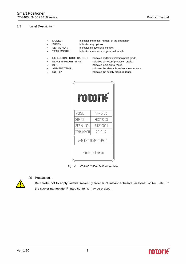
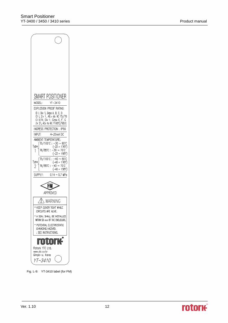
2.3 Label Description
• MODEL : Indicates the model number of the positioner.
• SUFFIX : Indicates any options.
• SERIAL NO. : Indicates unique serial number.
• YEAR.MONTH : Indicates manufactured year and month
• EXPLOSION PROOF RATING : Indicates certified explosion proof grade
• INGRESS PROTECTION : Indicates enclosure protection grade.
• INPUT : Indicates input signal range.
• AMBIENT TEMP. : Indicates the allowable ambient temperature.
• SUPPLY : Indicates the supply pressure range.
Fig. L-1: YT-3400 / 3450 / 3410 sticker label
※ Precautions
Be careful not to apply volatile solvent (hardener of instant adhesive, acetone, WD-40, etc.) to
the sticker nameplate. Printed contents may be erased.
Smart Positioner YT-3400 / 3450 / 3410 series Product manual
Ver. 1.10 9
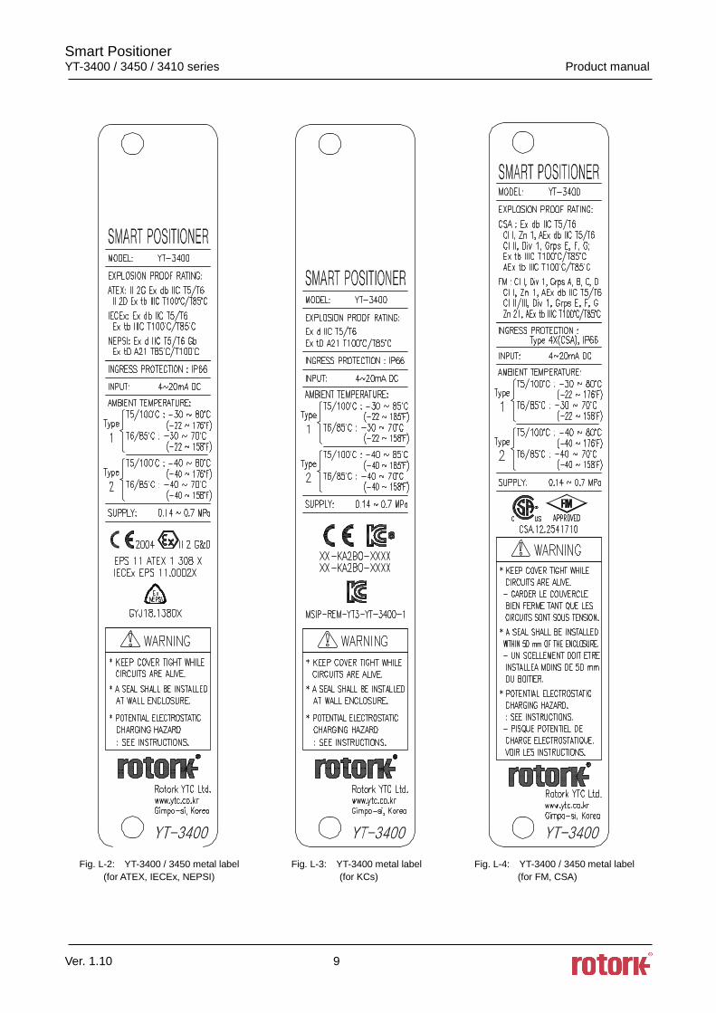
Fig. L-2: YT-3400 / 3450 metal label Fig. L-3: YT-3400 metal label Fig. L-4: YT-3400 / 3450 metal label
(for ATEX, IECEx, NEPSI) (for KCs) (for FM, CSA)
Smart Positioner YT-3400 / 3450 / 3410 series Product manual
Ver. 1.10 10
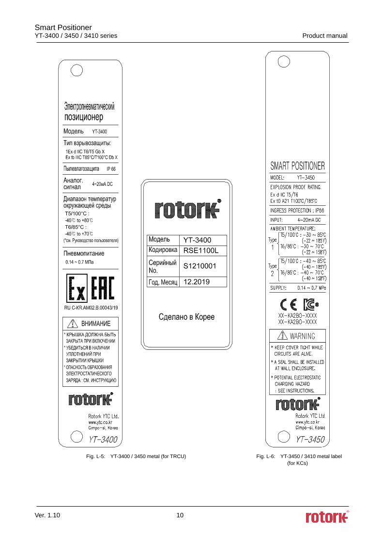
Fig. L-5: YT-3400 / 3450 metal (for TRCU) Fig. L-6: YT-3450 / 3410 metal label
(for KCs)
Smart Positioner YT-3400 / 3450 / 3410 series Product manual
Ver. 1.10 11
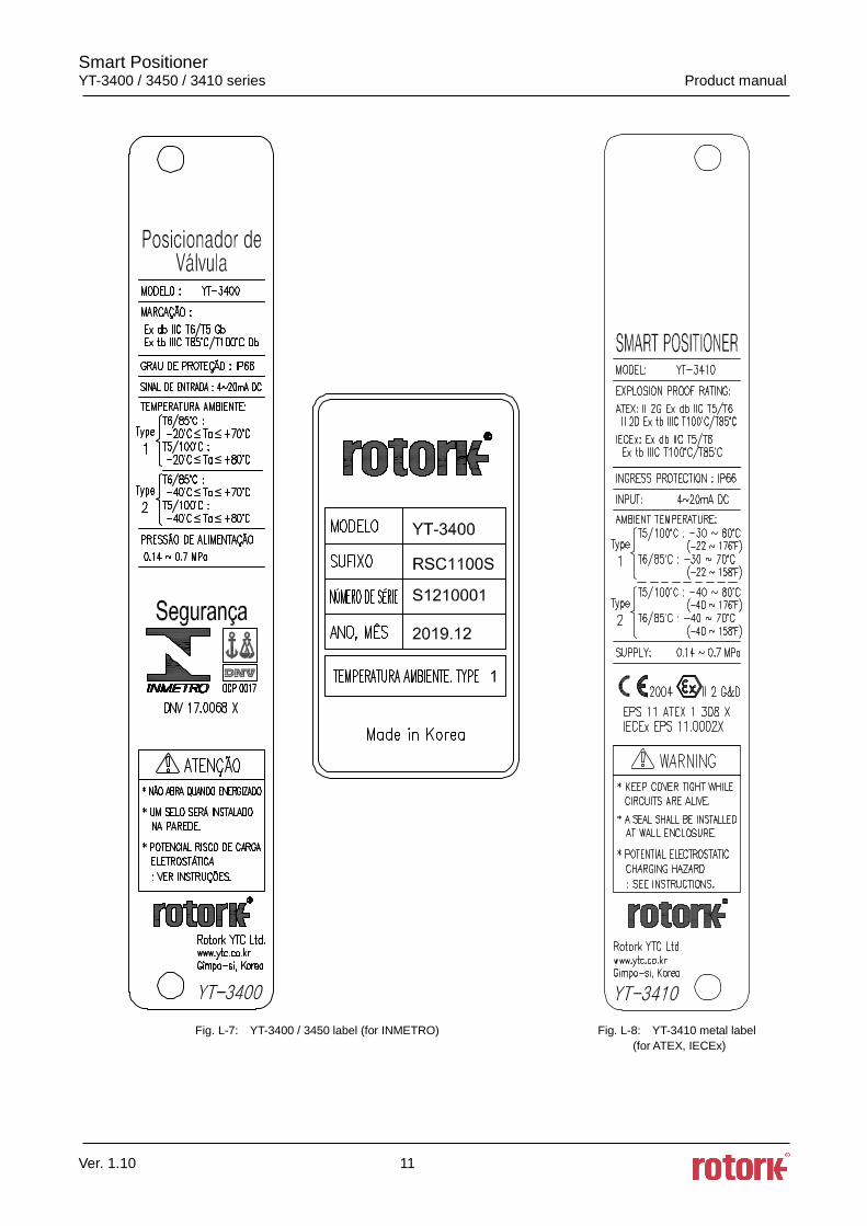
Fig. L-7: YT-3400 / 3450 label (for INMETRO) Fig. L-8: YT-3410 metal label
(for ATEX, IECEx)
Smart Positioner YT-3400 / 3450 / 3410 series Product manual
Ver. 1.10 12
Fig. L-9: YT-3410 label (for FM)
Smart Positioner YT-3400 / 3450 / 3410 series Product manual
Ver. 1.10 13
2.4 Product Code
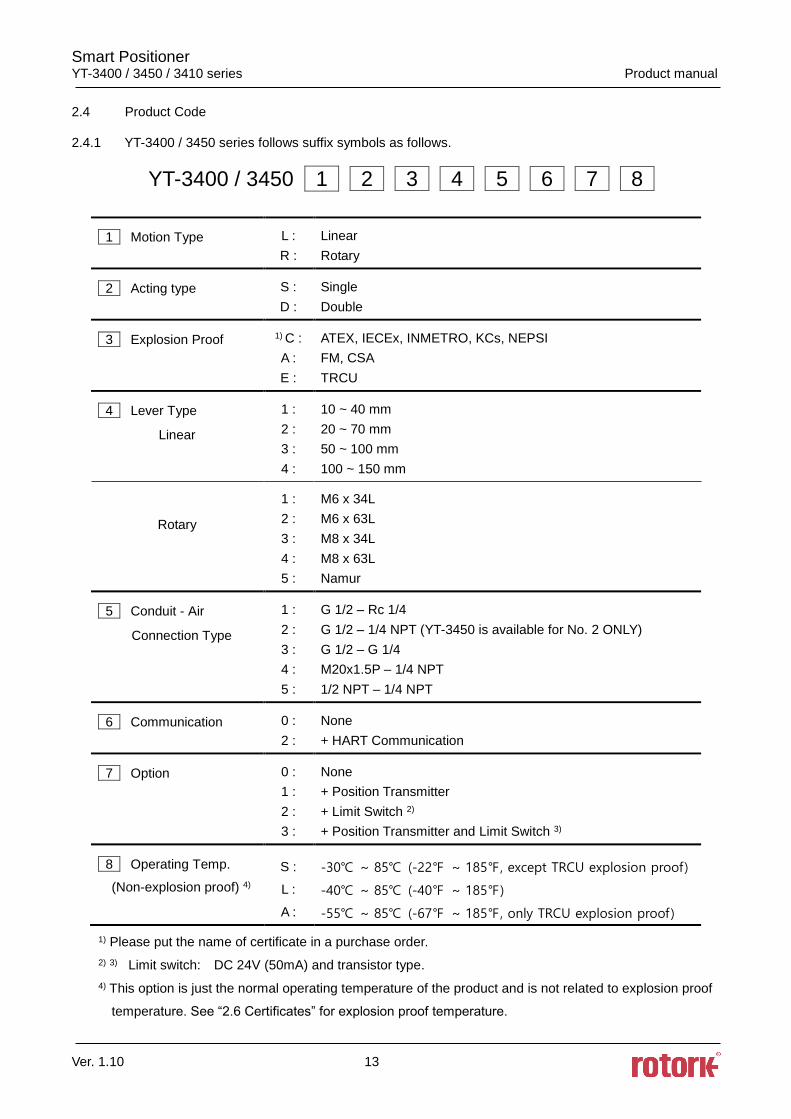
2.4.1 YT-3400 / 3450 series follows suffix symbols as follows.
YT-3400 / 3450 1 2 3 4 5 6 7 8
1 Motion Type L :
R :
Linear
Rotary
2 Acting type S :
D :
Single
Double
3 Explosion Proof 1) C :
A :
E :
ATEX, IECEx, INMETRO, KCs, NEPSI
FM, CSA
TRCU
4 Lever Type
Linear
1 :
2 :
3 :
4 :
10 ~ 40 mm
20 ~ 70 mm
50 ~ 100 mm
100 ~ 150 mm
Rotary
1 :
2 :
3 :
4 :
5 :
M6 x 34L
M6 x 63L
M8 x 34L
M8 x 63L
Namur
5 Conduit - Air
Connection Type
1 :
2 :
3 :
4 :
5 :
G 1/2 – Rc 1/4
G 1/2 – 1/4 NPT (YT-3450 is available for No. 2 ONLY)
G 1/2 – G 1/4
M20x1.5P – 1/4 NPT
1/2 NPT – 1/4 NPT
6 Communication 0 :
2 :
None
+ HART Communication
7 Option
0 :
1 :
2 :
3 :
None
+ Position Transmitter
+ Limit Switch 2)
+ Position Transmitter and Limit Switch 3)
8 Operating Temp.
(Non-explosion proof) 4)
S :
L :
A :
-30 ~ 85 (-22 ~ 185, except TRCU explosion proof)
-40 ~ 85 (-40 ~ 185)
-55 ~ 85 (-67 ~ 185, only TRCU explosion proof)
1) Please put the name of certificate in a purchase order.
2) 3) Limit switch: DC 24V (50mA) and transistor type.
4) This option is just the normal operating temperature of the product and is not related to explosion proof
temperature. See “2.6 Certificates” for explosion proof temperature.
Smart Positioner YT-3400 / 3450 / 3410 series Product manual
Ver. 1.10 14
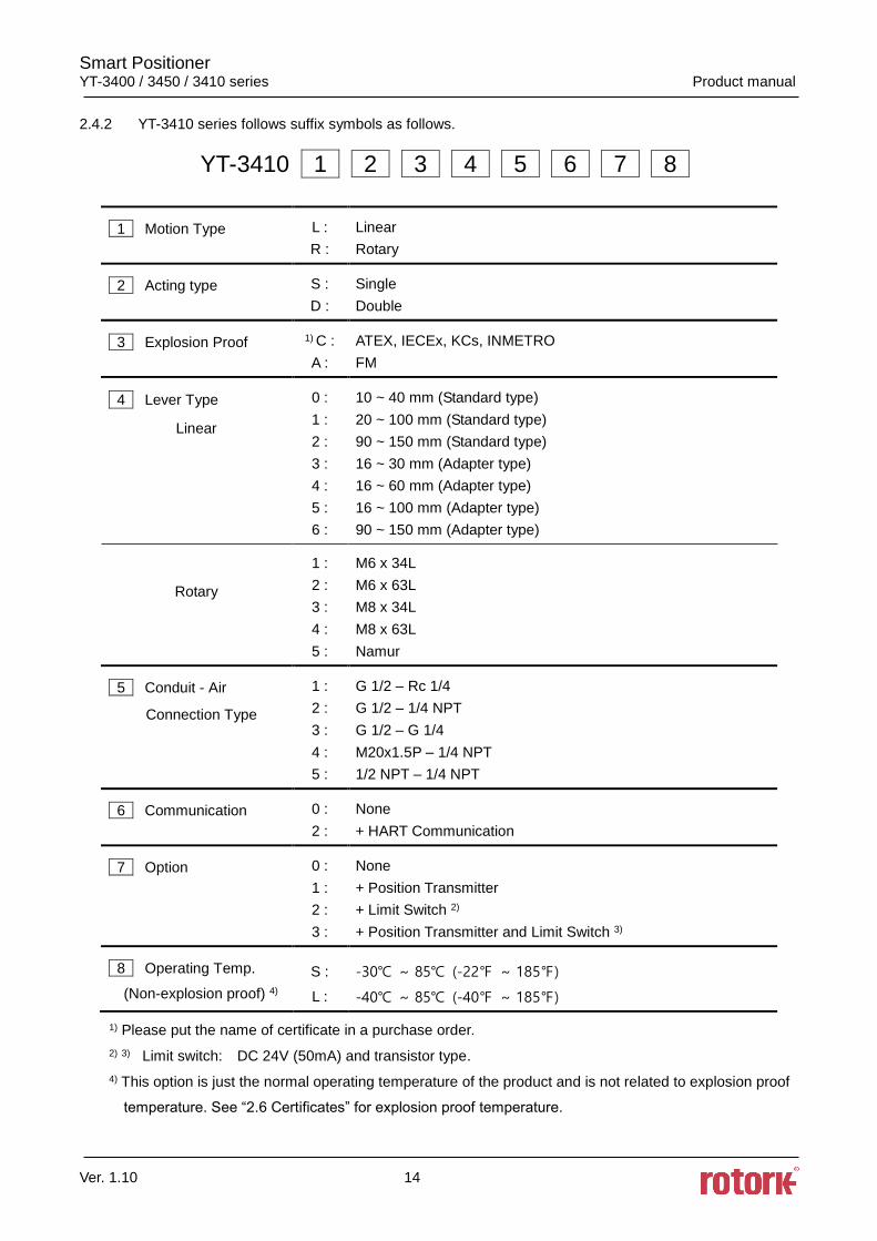
2.4.2 YT-3410 series follows suffix symbols as follows.
YT-3410 1 2 3 4 5 6 7 8
1 Motion Type L :
R :
Linear
Rotary
2 Acting type S :
D :
Single
Double
3 Explosion Proof 1) C :
A :
ATEX, IECEx, KCs, INMETRO
FM
4 Lever Type
Linear
0 :
1 :
2 :
3 :
4 :
5 :
6 :
10 ~ 40 mm (Standard type)
20 ~ 100 mm (Standard type)
90 ~ 150 mm (Standard type)
16 ~ 30 mm (Adapter type)
16 ~ 60 mm (Adapter type)
16 ~ 100 mm (Adapter type)
90 ~ 150 mm (Adapter type)
Rotary
1 :
2 :
3 :
4 :
5 :
M6 x 34L
M6 x 63L
M8 x 34L
M8 x 63L
Namur
5 Conduit - Air
Connection Type
1 :
2 :
3 :
4 :
5 :
G 1/2 – Rc 1/4
G 1/2 – 1/4 NPT
G 1/2 – G 1/4
M20x1.5P – 1/4 NPT
1/2 NPT – 1/4 NPT
6 Communication 0 :
2 :
None
+ HART Communication
7 Option
0 :
1 :
2 :
3 :
None
+ Position Transmitter
+ Limit Switch 2)
+ Position Transmitter and Limit Switch 3)
8 Operating Temp.
(Non-explosion proof) 4)
S :
L :
-30 ~ 85 (-22 ~ 185)
-40 ~ 85 (-40 ~ 185)
1) Please put the name of certificate in a purchase order.
2) 3) Limit switch: DC 24V (50mA) and transistor type.
4) This option is just the normal operating temperature of the product and is not related to explosion proof
temperature. See “2.6 Certificates” for explosion proof temperature.
Smart Positioner YT-3400 / 3450 / 3410 series Product manual
Ver. 1.10 15
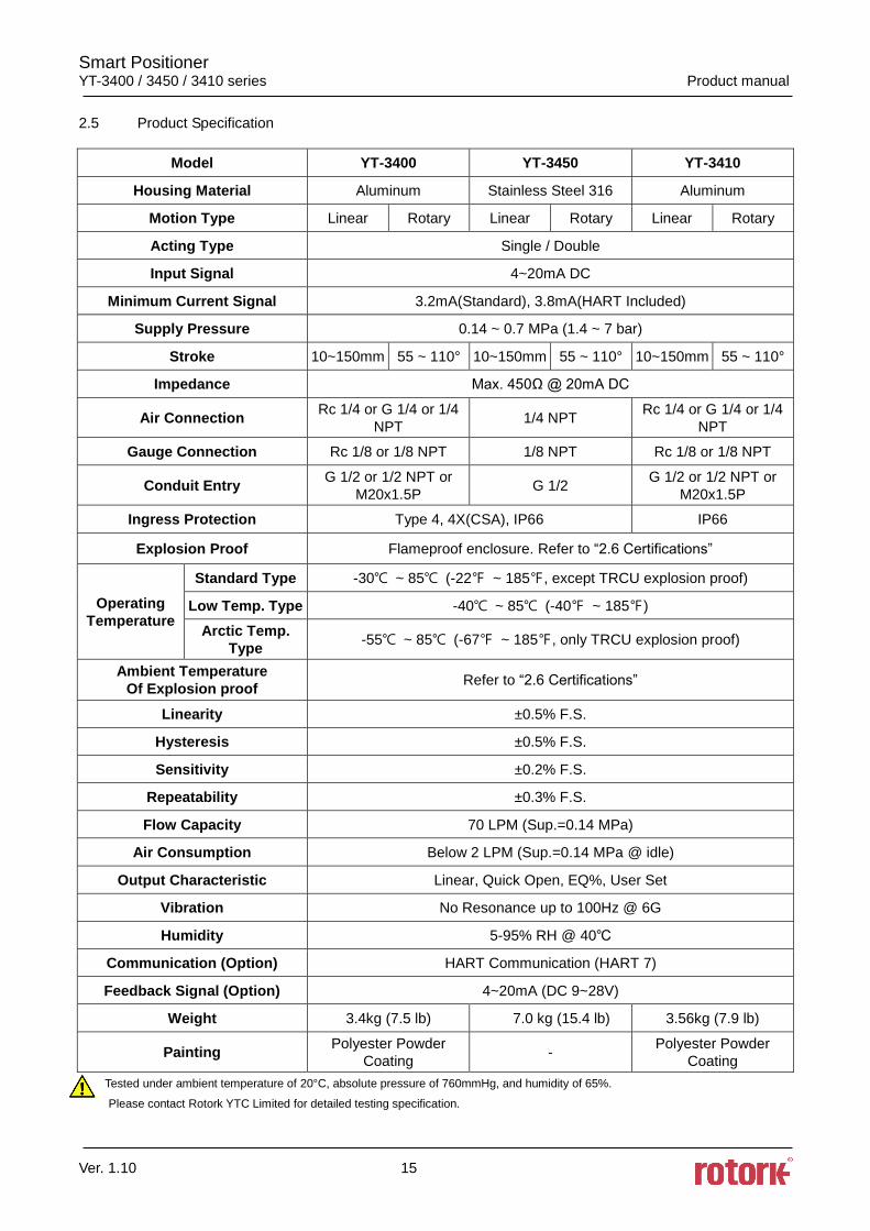
2.5 Product Specification
Model YT-3400 YT-3450 YT-3410
Housing Material Aluminum Stainless Steel 316 Aluminum
Motion Type Linear Rotary Linear Rotary Linear Rotary
Acting Type Single / Double
Input Signal 4~20mA DC
Minimum Current Signal 3.2mA(Standard), 3.8mA(HART Included)
Supply Pressure 0.14 ~ 0.7 MPa (1.4 ~ 7 bar)
Stroke 10~150mm 55 ~ 110° 10~150mm 55 ~ 110° 10~150mm 55 ~ 110°
Impedance Max. 450Ω @ 20mA DC
Air Connection Rc 1/4 or G 1/4 or 1/4
NPT 1/4 NPT
Rc 1/4 or G 1/4 or 1/4
NPT
Gauge Connection Rc 1/8 or 1/8 NPT 1/8 NPT Rc 1/8 or 1/8 NPT
Conduit Entry G 1/2 or 1/2 NPT or
M20x1.5P G 1/2
G 1/2 or 1/2 NPT or
M20x1.5P
Ingress Protection Type 4, 4X(CSA), IP66 IP66
Explosion Proof Flameproof enclosure. Refer to “2.6 Certifications”
Operating
Temperature
Standard Type -30 ~ 85 (-22 ~ 185, except TRCU explosion proof)
Low Temp. Type -40 ~ 85 (-40 ~ 185)
Arctic Temp.
Type -55 ~ 85 (-67 ~ 185, only TRCU explosion proof)
Ambient Temperature
Of Explosion proof Refer to “2.6 Certifications”
Linearity ±0.5% F.S.
Hysteresis ±0.5% F.S.
Sensitivity ±0.2% F.S.
Repeatability ±0.3% F.S.
Flow Capacity 70 LPM (Sup.=0.14 MPa)
Air Consumption Below 2 LPM (Sup.=0.14 MPa @ idle)
Output Characteristic Linear, Quick Open, EQ%, User Set
Vibration No Resonance up to 100Hz @ 6G
Humidity 5-95% RH @ 40
Communication (Option) HART Communication (HART 7)
Feedback Signal (Option) 4~20mA (DC 9~28V)
Weight 3.4kg (7.5 lb) 7.0 kg (15.4 lb) 3.56kg (7.9 lb)
Painting Polyester Powder
Coating -
Polyester Powder
Coating
Tested under ambient temperature of 20°C, absolute pressure of 760mmHg, and humidity of 65%.
Please contact Rotork YTC Limited for detailed testing specification.
Smart Positioner YT-3400 / 3450 / 3410 series Product manual
Ver. 1.10 16
2.6 Certifications
※ All certifications below are posted on Rotork YTC Limited homepage(www.ytc.co.kr).
KCs (Korea)
Type : Explosion proof construction for internal pressure
Rating : Ex d IIC T5/T6
Ex tD A21 T85/T100
Certification No. : XX-KA2BO-XXXX (YT-3400)
XX-KA2BO-XXXX (YT-3400)
XX-KA2BO-XXXX (YT-3450)
XX-KA2BO-XXXX (YT-3450)
XX-KA2BO-XXXX (YT-3410)
XX-KA2BO-XXXX (YT-3410)
Ambient temperature : -40 ~ +70(T6), -40 ~ +85(T5)
NEPSI (except YT-3410)
Type : Explosion proof construction for internal pressure
Rating : Ex d IIC T5/T6 Gb, Ex Td A21 IP66 T85/T100
Certification No. : GYJ18.1380X
Ambient temperature : -40 ~ +70(T6), -40 ~ +80(T5)
ATEX
Type : Explosion proof construction for internal pressure
Rating : II 2G Ex db IIC T5/T6, II 2D Ex tb IIIC T85/T100
Certification No. : EPS 11 ATEX 1 308 X
Ambient temperature : -40/-20 ~ +70 T6(T85), -40/-20 ~ +80 T5(T100)
IECEx
Type : Explosion proof construction for internal pressure
Rating : Ex db IIC T5/T6, Ex tb IIIC T85/T100
Certification No. : IECEx EPS 11.0002X
Ambient temperature : -40/-20 ~ +70 T6(T85), -40/-20 ~ +80 T5(T100)
CSA (except YT-3410)
Type : Explosion proof construction for internal pressure Rating : Ex db IIC T5 or T6
Class I, Zone 1, AEx db IIC T5 or T6
Class II, Division 1, Groups E, F and G; Ex tb IIIC T85/T100
AEx tb IIIC T85/T100
Type 4, 4X ; IP66 Certification No. : 2541710
Ambient temperature : -40 to +70(T6), -40 to +80(T5)
Smart Positioner YT-3400 / 3450 / 3410 series Product manual
Ver. 1.10 17
FM
Type : Explosion proof construction for internal pressure
Rating : Ex db IIC T5/T6, Ex tb IIIC T85/T100
XP/I/1/BCD/T6 Ta = -40 to +80
DIP/II, III/1/EFG/T6/Ta = -40 to +80; IP66
I/1/AEx db IIC T5 Ta = -40/-20 to +80
I/1/AEx db IIC T6 Ta = -40/-20 to +70
21/AEx tb IIIC T85/T100
T6 Ta = -40/-20 to +70
T5 Ta = -40/-20 to +80; IP66
Certification No. : FM16US0132X
Ambient temperature : (T6) -40 to +70, (T5) -40 to +80
TRCU (except YT-3410)
Type : Explosion proof construction for internal pressure
Rating : 1Ex d IIC T6/T5 Gb X, Ex tb IIIC T85°C/T100°C Db X, IP66
Certification No. : RU C-KR.MЮ62.B.04778
Ambient temperature : -55 ~ +70 (T6/T85), -55 ~ +80 (T5/T100)
INMETRO (Brazil)
Rating : Ex db IIC T5/T6 Gb IP66, Ex tb IIC T85°C/T100°C Db IP66 Certification No. : DNV 17.0068 X
Ambient temperature : -40 ~ +70 (T6), -40 ~ +80 (T5)
SIL2 (in a redundant structure up to SIL 3)
Intended application : Safety function is defined as to move into fail-safe-position, when
signal to positioner is interrupted.
Certification No. : 968/V 460.03/19
Electromagnetic Compatibility (EMC)
- EMC directive 2014/30/EC from April 2016
- EC Directive for CE conformity marking
- Registration No. : MSIP-REM-YT3-YT-3400-1
Smart Positioner YT-3400 / 3450 / 3410 series Product manual
Ver. 1.10 18
2.7 Parts and Assembly
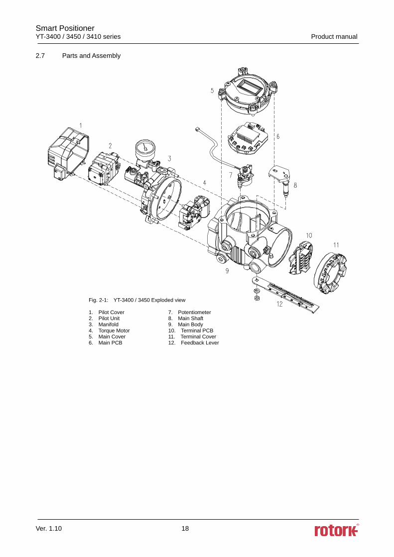
Fig. 2-1: YT-3400 / 3450 Exploded view
1. Pilot Cover 7. Potentiometer 2. Pilot Unit 8. Main Shaft 3. Manifold 9. Main Body 4. Torque Motor 10. Terminal PCB 5. Main Cover 11. Terminal Cover 6. Main PCB 12. Feedback Lever
Smart Positioner YT-3400 / 3450 / 3410 series Product manual
Ver. 1.10 19
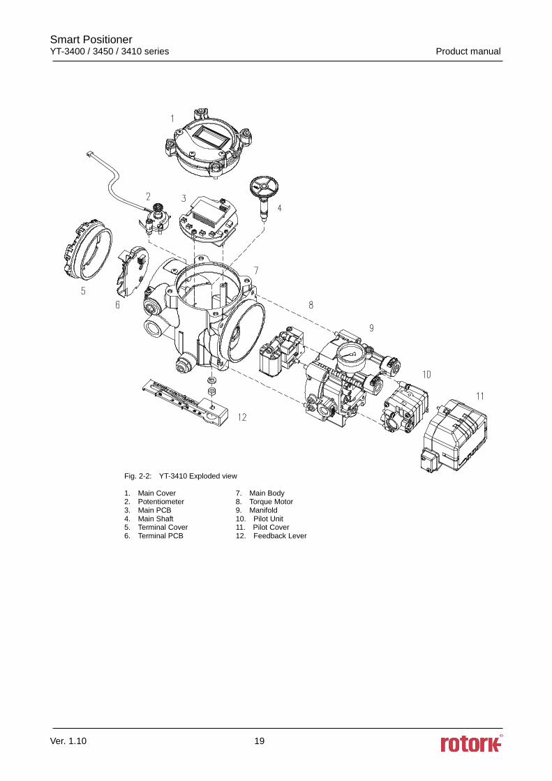
Fig. 2-2: YT-3410 Exploded view
1. Main Cover 7. Main Body 2. Potentiometer 8. Torque Motor 3. Main PCB 9. Manifold 4. Main Shaft 10. Pilot Unit 5. Terminal Cover 11. Pilot Cover 6. Terminal PCB 12. Feedback Lever
Smart Positioner YT-3400 / 3450 / 3410 series Product manual
Ver. 1.10 20
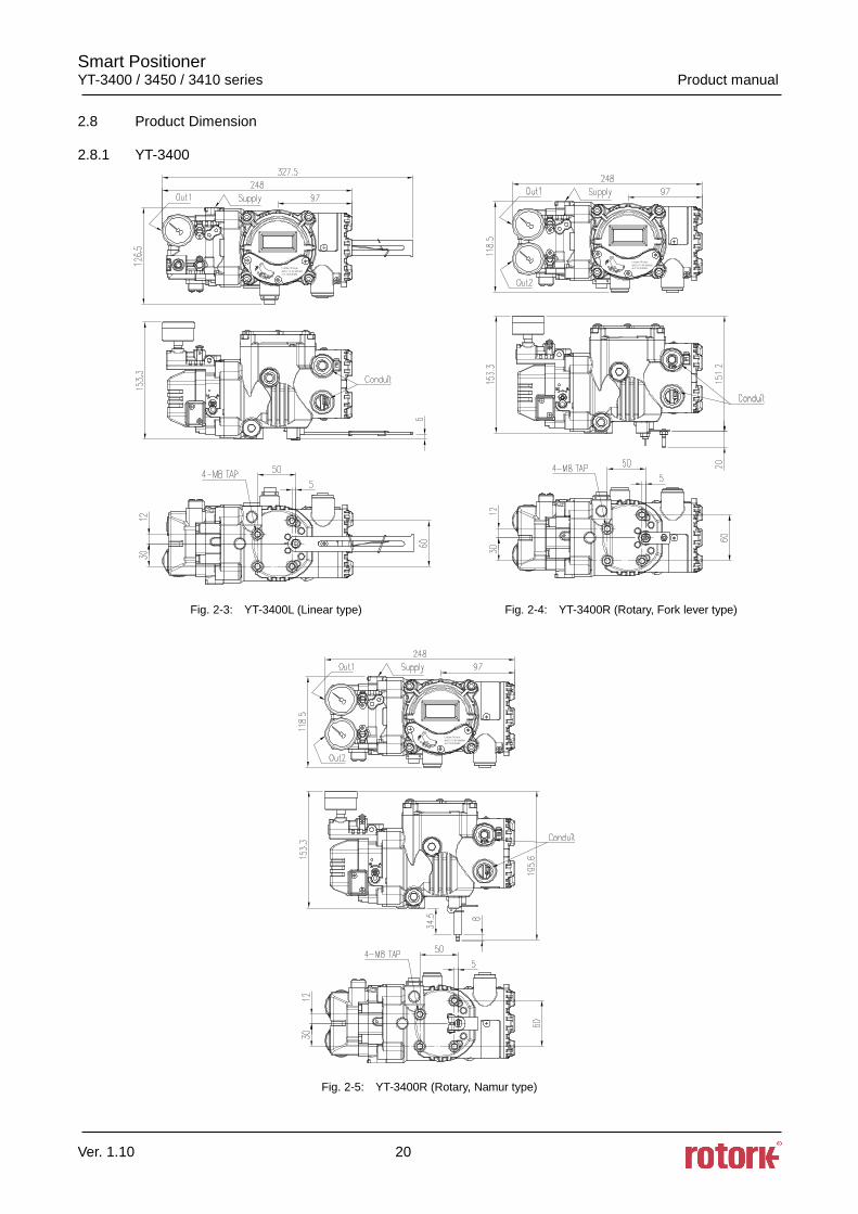
2.8 Product Dimension
2.8.1 YT-3400
Fig. 2-3: YT-3400L (Linear type) Fig. 2-4: YT-3400R (Rotary, Fork lever type)
Fig. 2-5: YT-3400R (Rotary, Namur type)
Smart Positioner YT-3400 / 3450 / 3410 series Product manual
Ver. 1.10 21
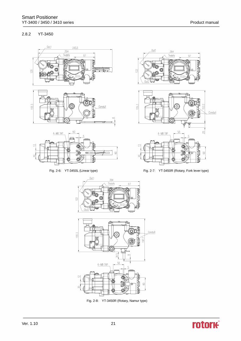
2.8.2 YT-3450
Fig. 2-6: YT-3450L (Linear type) Fig. 2-7: YT-3450R (Rotary, Fork lever type)
Fig. 2-8: YT-3450R (Rotary, Namur type)
Smart Positioner YT-3400 / 3450 / 3410 series Product manual
Ver. 1.10 22
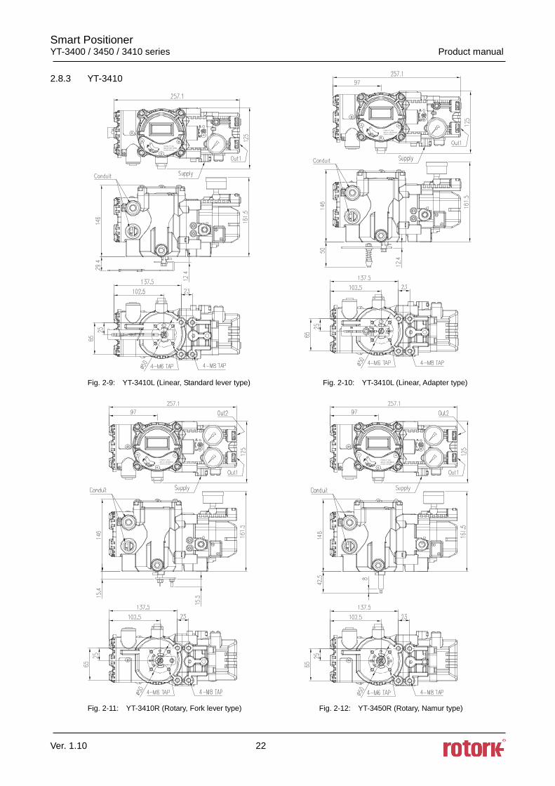
2.8.3 YT-3410
Fig. 2-9: YT-3410L (Linear, Standard lever type) Fig. 2-10: YT-3410L (Linear, Adapter type)
Fig. 2-11: YT-3410R (Rotary, Fork lever type) Fig. 2-12: YT-3450R (Rotary, Namur type)
Smart Positioner YT-3400 / 3450 / 3410 series Product manual
Ver. 1.10 23
3. Installation
3.1 Safety
When installing a positioner, please ensure to read and follow safety instructions.
Any input or supply pressures to valve, actuator, and / or to other related devices must be turned
off.
Use bypass valve or other supportive equipment to avoid entire system “shut down”.
Ensure there is no remaining pressure in the actuator.
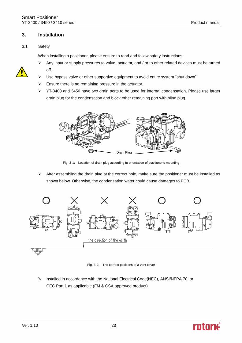
YT-3400 and 3450 have two drain ports to be used for internal condensation. Please use larger
drain plug for the condensation and block other remaining port with blind plug.
Fig. 3-1: Location of drain plug according to orientation of positioner’s mounting
After assembling the drain plug at the correct hole, make sure the positioner must be installed as
shown below. Otherwise, the condensation water could cause damages to PCB.
Fig. 3-2: The correct positions of a vent cover
※ Installed in accordance with the National Electrical Code(NEC), ANSI/NFPA 70, or
CEC Part 1 as applicable.(FM & CSA approved product)
Drain Plug
Smart Positioner YT-3400 / 3450 / 3410 series Product manual
Ver. 1.10 24
3.2 Tools for installation
Hex key set for hex socket cap bolts
(+) & (-) Screw drivers
Spanners for hexagonal-head bolts
3.3 Linear positioner Installation
Linear positioner should be installed on linear motion valves such as globe or gate type which uses
spring return type diaphragm or piston actuators.
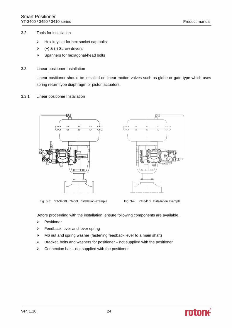
3.3.1 Linear positioner Installation
Fig. 3-3: YT-3400L / 3450L Installation example Fig. 3-4: YT-3410L Installation example
Before proceeding with the installation, ensure following components are available.
Positioner
Feedback lever and lever spring
M6 nut and spring washer (fastening feedback lever to a main shaft)
Bracket, bolts and washers for positioner – not supplied with the positioner
Connection bar – not supplied with the positioner
Smart Positioner YT-3400 / 3450 / 3410 series Product manual
Ver. 1.10 25
3.3.1.1 Safety
Proper bracket must be made in order to adapt the positioner on the actuator yoke.
Please consider following important points when a bracket is being designed.
Positioner’s feedback lever must be vertical to the valve stem at 50% of the valve stroke.
The connection bar of the actuator clamp for the feedback lever should be installed in such a
way that the valve stroke length coincides with the corresponding figure in “mm” marked on the
feedback lever. Improper setting may cause poor linearity
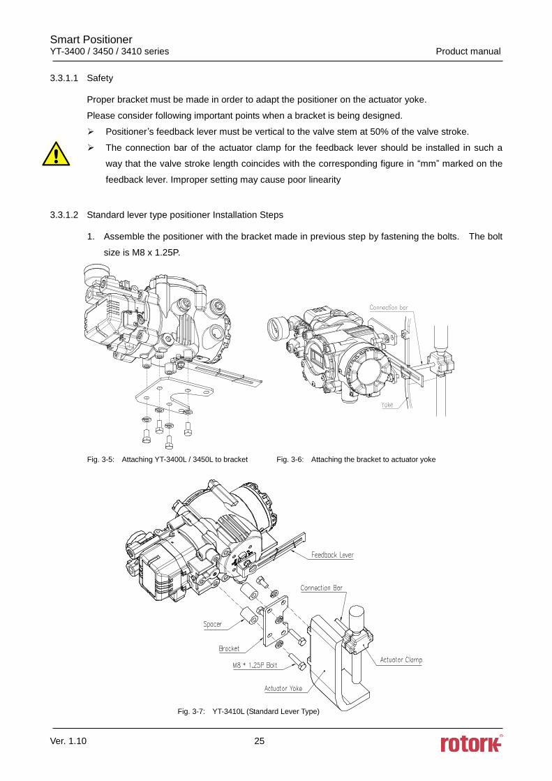
3.3.1.2 Standard lever type positioner Installation Steps
1. Assemble the positioner with the bracket made in previous step by fastening the bolts. The bolt
size is M8 x 1.25P.
Fig. 3-5: Attaching YT-3400L / 3450L to bracket Fig. 3-6: Attaching the bracket to actuator yoke
Fig. 3-7: YT-3410L (Standard Lever Type)
Smart Positioner YT-3400 / 3450 / 3410 series Product manual
Ver. 1.10 26
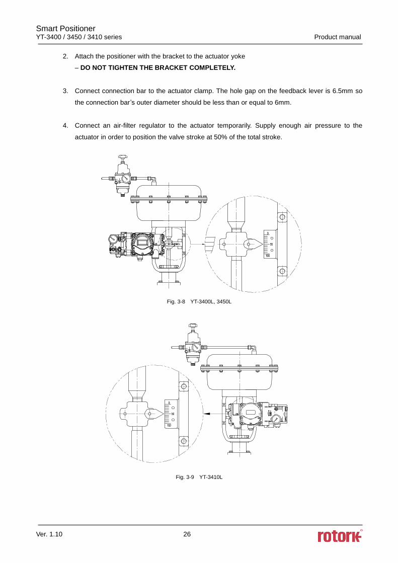
2. Attach the positioner with the bracket to the actuator yoke
– DO NOT TIGHTEN THE BRACKET COMPLETELY.
3. Connect connection bar to the actuator clamp. The hole gap on the feedback lever is 6.5mm so
the connection bar’s outer diameter should be less than or equal to 6mm.
4. Connect an air-filter regulator to the actuator temporarily. Supply enough air pressure to the
actuator in order to position the valve stroke at 50% of the total stroke.
Fig. 3-8 YT-3400L, 3450L
Fig. 3-9 YT-3410L
Smart Positioner YT-3400 / 3450 / 3410 series Product manual
Ver. 1.10 27
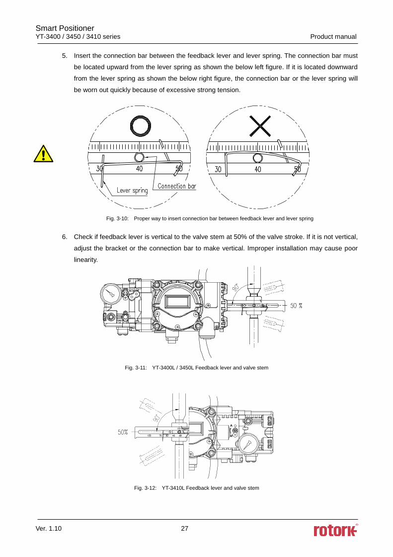
5. Insert the connection bar between the feedback lever and lever spring. The connection bar must
be located upward from the lever spring as shown the below left figure. If it is located downward
from the lever spring as shown the below right figure, the connection bar or the lever spring will
be worn out quickly because of excessive strong tension.
Fig. 3-10: Proper way to insert connection bar between feedback lever and lever spring
6. Check if feedback lever is vertical to the valve stem at 50% of the valve stroke. If it is not vertical,
adjust the bracket or the connection bar to make vertical. Improper installation may cause poor
linearity.
Fig. 3-11: YT-3400L / 3450L Feedback lever and valve stem
Fig. 3-12: YT-3410L Feedback lever and valve stem
Smart Positioner YT-3400 / 3450 / 3410 series Product manual
Ver. 1.10 28
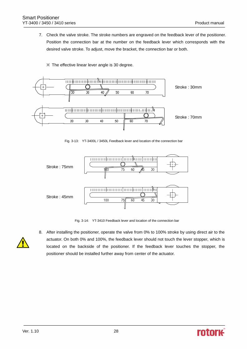
7. Check the valve stroke. The stroke numbers are engraved on the feedback lever of the positioner.
Position the connection bar at the number on the feedback lever which corresponds with the
desired valve stroke. To adjust, move the bracket, the connection bar or both.
※ The effective linear lever angle is 30 degree.
Stroke : 30mm
Stroke : 70mm
Fig. 3-13: YT-3400L / 3450L Feedback lever and location of the connection bar
Stroke : 75mm
Stroke : 45mm
Fig. 3-14: YT-3410 Feedback lever and location of the connection bar
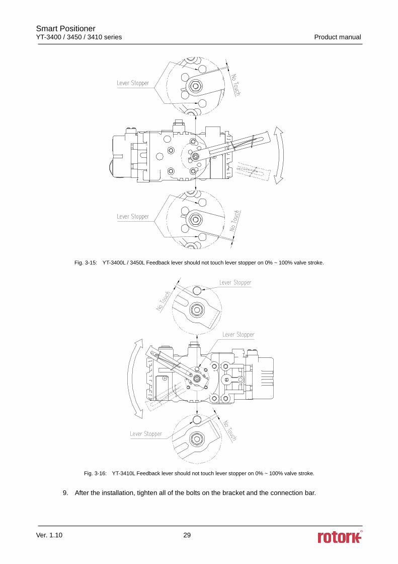
8. After installing the positioner, operate the valve from 0% to 100% stroke by using direct air to the
actuator. On both 0% and 100%, the feedback lever should not touch the lever stopper, which is
located on the backside of the positioner. If the feedback lever touches the stopper, the
positioner should be installed further away from center of the actuator.
Smart Positioner YT-3400 / 3450 / 3410 series Product manual
Ver. 1.10 29
Fig. 3-15: YT-3400L / 3450L Feedback lever should not touch lever stopper on 0% ~ 100% valve stroke.
Fig. 3-16: YT-3410L Feedback lever should not touch lever stopper on 0% ~ 100% valve stroke.
9. After the installation, tighten all of the bolts on the bracket and the connection bar.
Smart Positioner YT-3400 / 3450 / 3410 series Product manual
Ver. 1.10 30
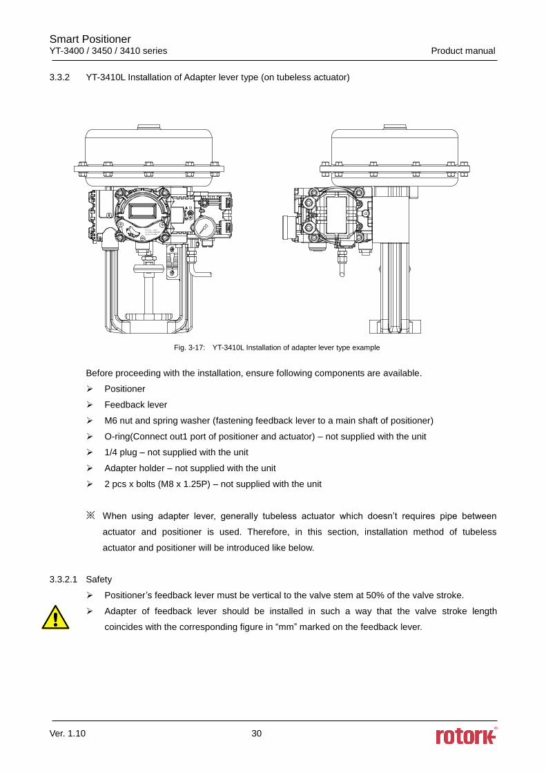
3.3.2 YT-3410L Installation of Adapter lever type (on tubeless actuator)
Fig. 3-17: YT-3410L Installation of adapter lever type example
Before proceeding with the installation, ensure following components are available.
Positioner
Feedback lever
M6 nut and spring washer (fastening feedback lever to a main shaft of positioner)
O-ring(Connect out1 port of positioner and actuator) – not supplied with the unit
1/4 plug – not supplied with the unit
Adapter holder – not supplied with the unit
2 pcs x bolts (M8 x 1.25P) – not supplied with the unit
※ When using adapter lever, generally tubeless actuator which doesn’t requires pipe between
actuator and positioner is used. Therefore, in this section, installation method of tubeless
actuator and positioner will be introduced like below.
3.3.2.1 Safety
Positioner’s feedback lever must be vertical to the valve stem at 50% of the valve stroke.
Adapter of feedback lever should be installed in such a way that the valve stroke length
coincides with the corresponding figure in “mm” marked on the feedback lever.
Smart Positioner YT-3400 / 3450 / 3410 series Product manual
Ver. 1.10 31
3.3.2.2 Adapter lever type positioner Installation Steps
1. Remove Out1 Plug(Fig. 3-19) on the bottom of the positioner. Plug up out1 port of gauge block
with 1/4 plug using sealant.
2. Check the valve stroke. The stroke numbers are engraved on the feedback lever of the
positioner. Position the adapter at the number on the feedback lever which corresponds with
the desired valve stroke. To adjust, loosen M6 nut behind the adapter, move the adapter to
correct position, and then tighten the M6 nut.
Stroke : 75mm
Stroke : 30mm
Fig. 3-18: YT-3410L Feedback lever and location of the connection bar
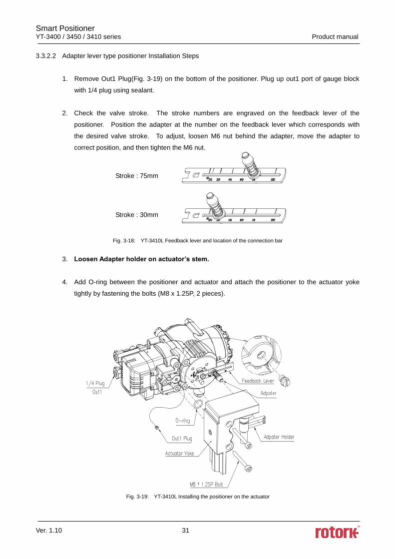
3. Loosen Adapter holder on actuator’s stem.
4. Add O-ring between the positioner and actuator and attach the positioner to the actuator yoke
tightly by fastening the bolts (M8 x 1.25P, 2 pieces).
Fig. 3-19: YT-3410L Installing the positioner on the actuator
Smart Positioner YT-3400 / 3450 / 3410 series Product manual
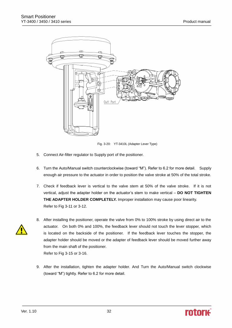
Ver. 1.10 32
Fig. 3-20: YT-3410L (Adapter Lever Type)
5. Connect Air-filter regulator to Supply port of the positioner.
6. Turn the Auto/Manual switch counterclockwise (toward “M”). Refer to 6.2 for more detail. Supply
enough air pressure to the actuator in order to position the valve stroke at 50% of the total stroke.
7. Check if feedback lever is vertical to the valve stem at 50% of the valve stroke. If it is not
vertical, adjust the adapter holder on the actuator’s stem to make vertical – DO NOT TIGHTEN
THE ADAPTER HOLDER COMPLETELY. Improper installation may cause poor linearity.
Refer to Fig 3-11 or 3-12.
8. After installing the positioner, operate the valve from 0% to 100% stroke by using direct air to the
actuator. On both 0% and 100%, the feedback lever should not touch the lever stopper, which
is located on the backside of the positioner. If the feedback lever touches the stopper, the
adapter holder should be moved or the adapter of feedback lever should be moved further away
from the main shaft of the positioner.
Refer to Fig 3-15 or 3-16.
9. After the installation, tighten the adapter holder. And Turn the Auto/Manual switch clockwise
(toward “M”) tightly. Refer to 6.2 for more detail.
Smart Positioner YT-3400 / 3450 / 3410 series Product manual
Ver. 1.10 33
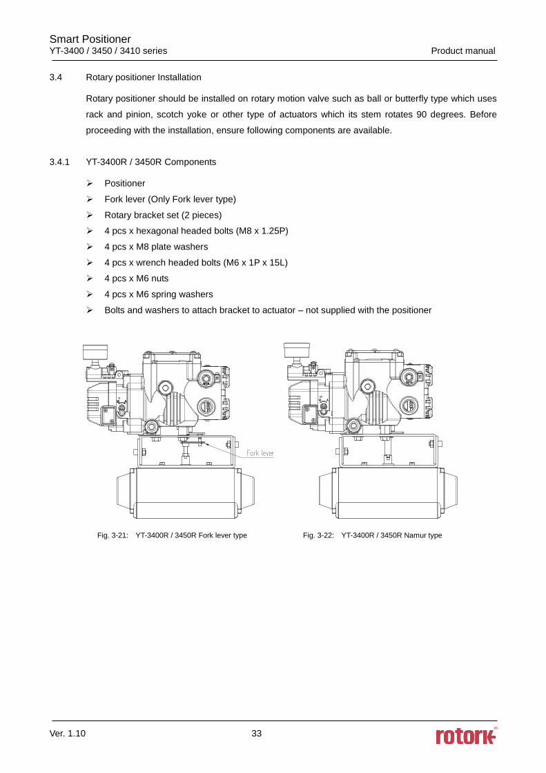
3.4 Rotary positioner Installation
Rotary positioner should be installed on rotary motion valve such as ball or butterfly type which uses
rack and pinion, scotch yoke or other type of actuators which its stem rotates 90 degrees. Before
proceeding with the installation, ensure following components are available.
3.4.1 YT-3400R / 3450R Components
Positioner
Fork lever (Only Fork lever type)
Rotary bracket set (2 pieces)
4 pcs x hexagonal headed bolts (M8 x 1.25P)
4 pcs x M8 plate washers
4 pcs x wrench headed bolts (M6 x 1P x 15L)
4 pcs x M6 nuts
4 pcs x M6 spring washers
Bolts and washers to attach bracket to actuator – not supplied with the positioner
Fig. 3-21: YT-3400R / 3450R Fork lever type Fig. 3-22: YT-3400R / 3450R Namur type
Smart Positioner YT-3400 / 3450 / 3410 series Product manual
Ver. 1.10 34
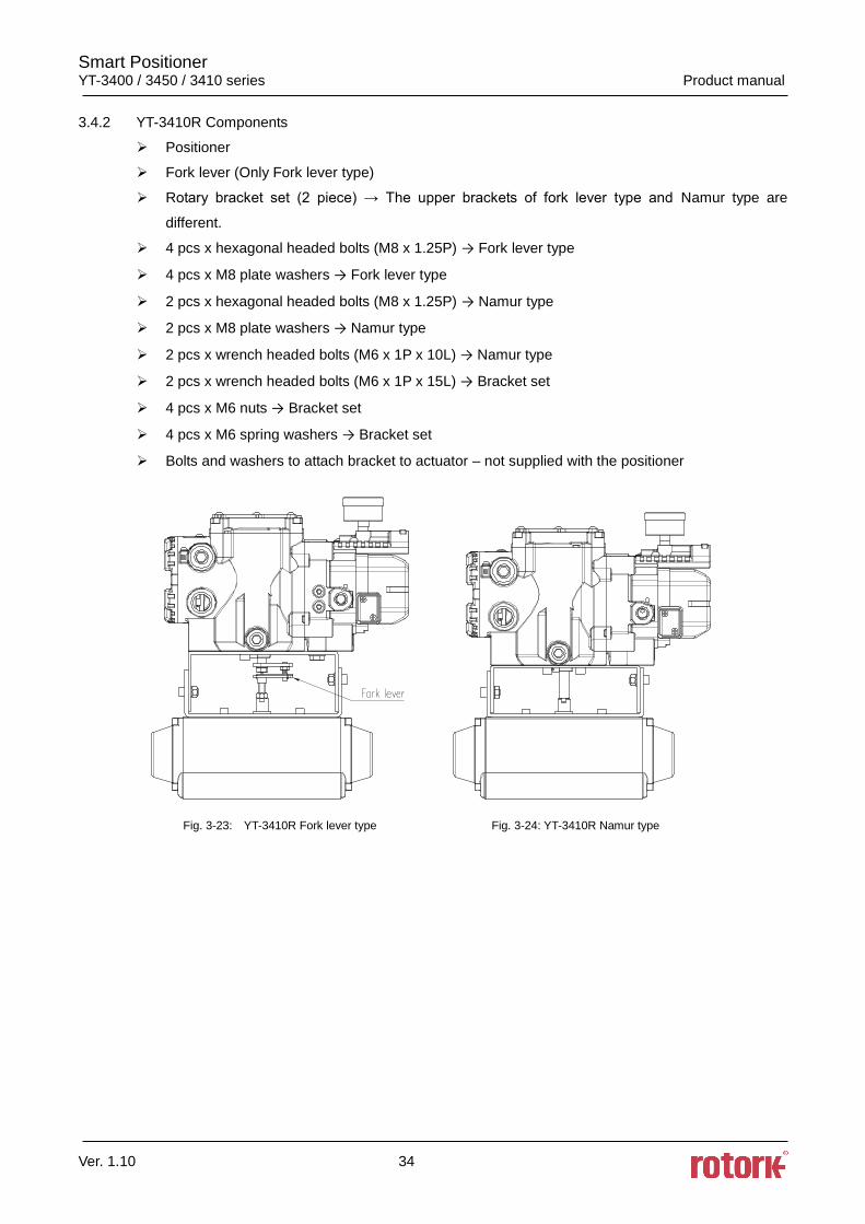
3.4.2 YT-3410R Components
Positioner
Fork lever (Only Fork lever type)
Rotary bracket set (2 piece) → The upper brackets of fork lever type and Namur type are
different.
4 pcs x hexagonal headed bolts (M8 x 1.25P) → Fork lever type
4 pcs x M8 plate washers → Fork lever type
2 pcs x hexagonal headed bolts (M8 x 1.25P) → Namur type
2 pcs x M8 plate washers → Namur type
2 pcs x wrench headed bolts (M6 x 1P x 10L) → Namur type
2 pcs x wrench headed bolts (M6 x 1P x 15L) → Bracket set
4 pcs x M6 nuts → Bracket set
4 pcs x M6 spring washers → Bracket set
Bolts and washers to attach bracket to actuator – not supplied with the positioner
Fig. 3-23: YT-3410R Fork lever type Fig. 3-24: YT-3410R Namur type
Smart Positioner YT-3400 / 3450 / 3410 series Product manual
Ver. 1.10 35
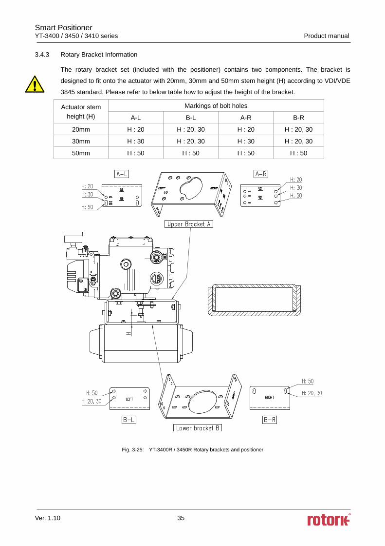
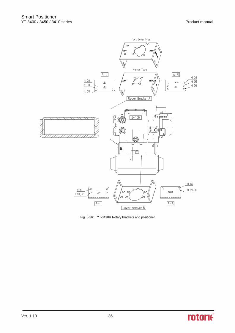
3.4.3 Rotary Bracket Information
The rotary bracket set (included with the positioner) contains two components. The bracket is
designed to fit onto the actuator with 20mm, 30mm and 50mm stem height (H) according to VDI/VDE
3845 standard. Please refer to below table how to adjust the height of the bracket.
Actuator stem
height (H)
Markings of bolt holes
A-L B-L A-R B-R
20mm H : 20 H : 20, 30 H : 20 H : 20, 30
30mm H : 30 H : 20, 30 H : 30 H : 20, 30
50mm H : 50 H : 50 H : 50 H : 50
Fig. 3-25: YT-3400R / 3450R Rotary brackets and positioner
Smart Positioner YT-3400 / 3450 / 3410 series Product manual
Ver. 1.10 36
Fig. 3-26: YT-3410R Rotary brackets and positioner
Smart Positioner YT-3400 / 3450 / 3410 series Product manual
Ver. 1.10 37
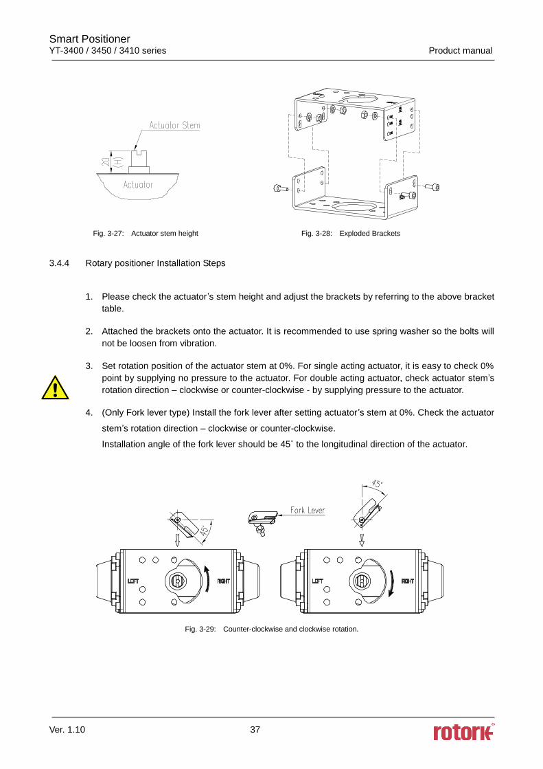
Fig. 3-27: Actuator stem height Fig. 3-28: Exploded Brackets
3.4.4 Rotary positioner Installation Steps
1. Please check the actuator’s stem height and adjust the brackets by referring to the above bracket
table. 2. Attached the brackets onto the actuator. It is recommended to use spring washer so the bolts will
not be loosen from vibration. 3. Set rotation position of the actuator stem at 0%. For single acting actuator, it is easy to check 0%
point by supplying no pressure to the actuator. For double acting actuator, check actuator stem’s
rotation direction – clockwise or counter-clockwise - by supplying pressure to the actuator. 4. (Only Fork lever type) Install the fork lever after setting actuator ’s stem at 0%. Check the actuator
stem’s rotation direction – clockwise or counter-clockwise.
Installation angle of the fork lever should be 45˚ to the longitudinal direction of the actuator.
Fig. 3-29: Counter-clockwise and clockwise rotation.
Smart Positioner YT-3400 / 3450 / 3410 series Product manual
Ver. 1.10 38
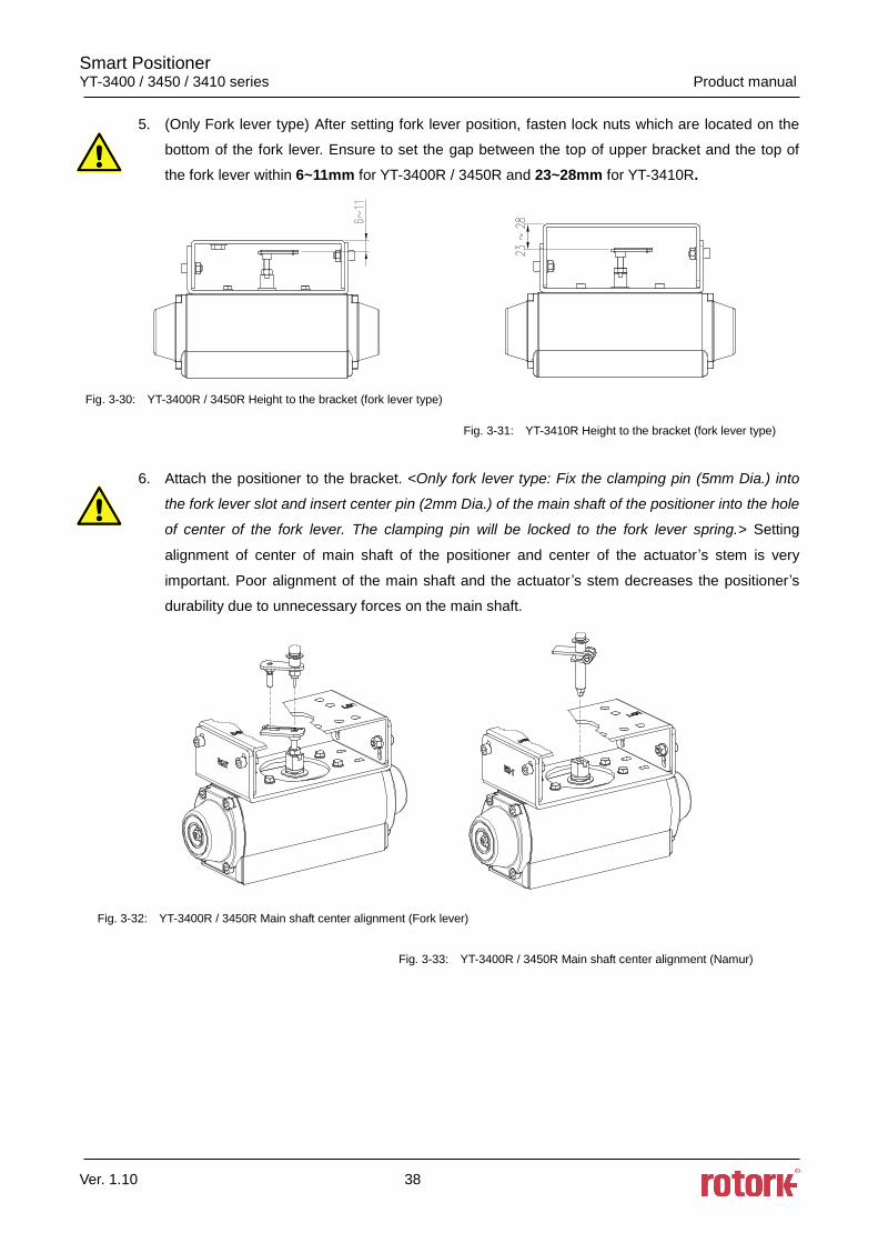
5. (Only Fork lever type) After setting fork lever position, fasten lock nuts which are located on the
bottom of the fork lever. Ensure to set the gap between the top of upper bracket and the top of
the fork lever within 6~11mm for YT-3400R / 3450R and 23~28mm for YT-3410R.
Fig. 3-30: YT-3400R / 3450R Height to the bracket (fork lever type)
Fig. 3-31: YT-3410R Height to the bracket (fork lever type)
6. Attach the positioner to the bracket. <Only fork lever type: Fix the clamping pin (5mm Dia.) into
the fork lever slot and insert center pin (2mm Dia.) of the main shaft of the positioner into the hole
of center of the fork lever. The clamping pin will be locked to the fork lever spring.> Setting
alignment of center of main shaft of the positioner and center of the actuator ’s stem is very
important. Poor alignment of the main shaft and the actuator ’s stem decreases the positioner’s
durability due to unnecessary forces on the main shaft.
Fig. 3-32: YT-3400R / 3450R Main shaft center alignment (Fork lever)
Fig. 3-33: YT-3400R / 3450R Main shaft center alignment (Namur)
Smart Positioner YT-3400 / 3450 / 3410 series Product manual
Ver. 1.10 39
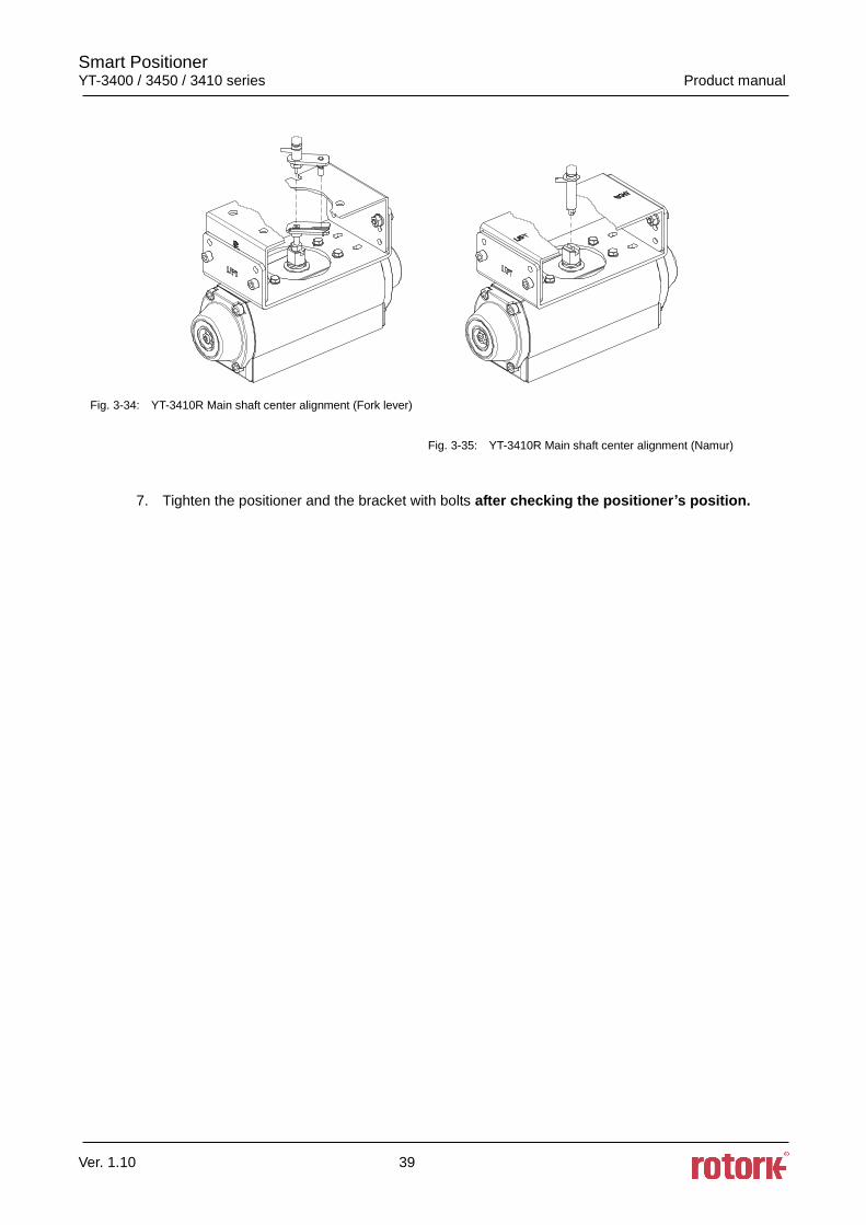
Fig. 3-34: YT-3410R Main shaft center alignment (Fork lever)
Fig. 3-35: YT-3410R Main shaft center alignment (Namur)
7. Tighten the positioner and the bracket with bolts after checking the positioner’s position.
Smart Positioner YT-3400 / 3450 / 3410 series Product manual
Ver. 1.10 40
4. Connection - Air
4.1 Safety
Supply pressure should be clean and dry air – avoiding moisture, oil and dust.
Always recommended to use air filter regulator (i.e. YT-200 series).
Rotork YTC Limited has not tested positioner’s operation with any other gases other than
clean air. Please contact Rotork YTC Limited for any questions.
A conduit seal is required within 50mm of the enclosure to prevent the passage of a process
medium gas from migrating into the conduit system to a possible ignition source.
4.2 Supply Pressure Condition
Dry air with dew point of at least 10 lower than ambient temperature.
Avoid from dusty air. Use 5 micron or smaller filter.
Avoid oil.
Comply with ISO 8573-1 or ISA 7.0.01.
Supply pressure range is 0.14 ~0.7 MPa (1.4 ~ 7 bar)
Set air filter regulator’s pressure level 10% higher than actuator’s spring range pressure.
4.3 Piping Condition
Ensure inside of pipe is clean of obstructions.
Do not use pipeline that is squeezed or shows any type of damamges.
Pipeline should have more than 6mm of inner diameter (10mm outer diameter) to maintain flow
rate.
The length of pipeline system should not be extremely long. Longer pipeline system may affect
flow rate due to the friction inside of the pipeline.
Smart Positioner YT-3400 / 3450 / 3410 series Product manual
Ver. 1.10 41
4.4 Connection – Piping with actuator
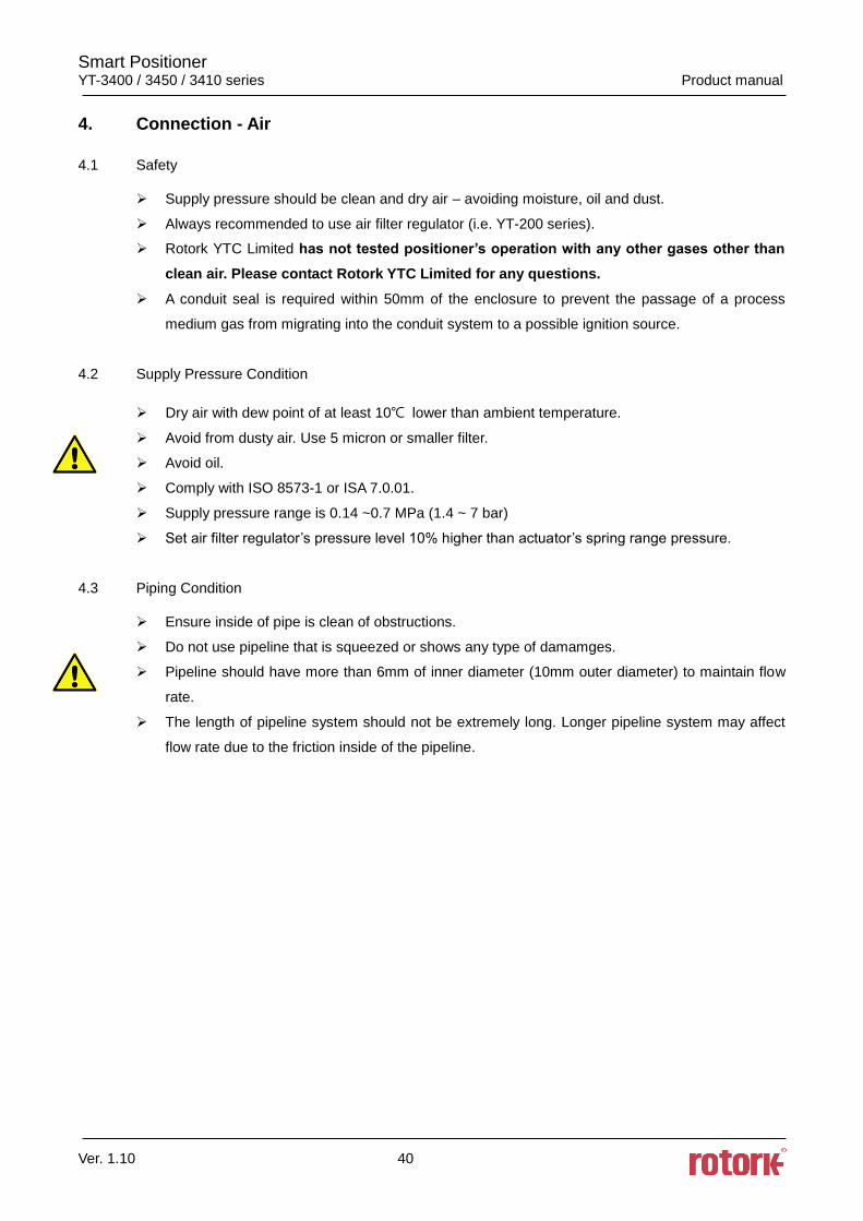
4.4.1 Single acting actuator
Singe acting type positioner is set to use only OUT1 port. OUT1 port of positioner should be
connected with supply port of actuator when using spring return actuator of single acting type.
Fig. 4-1: YT-3400L / 3450L Single acting linear actuator Fig. 4-2: YT-3400R / 3450R Single acting rotary actuator
Fig. 4-3: YT-3410L Single acting linear actuator Fig. 4-4: YT-3410R Single acting rotary actuator
Smart Positioner YT-3400 / 3450 / 3410 series Product manual
Ver. 1.10 42
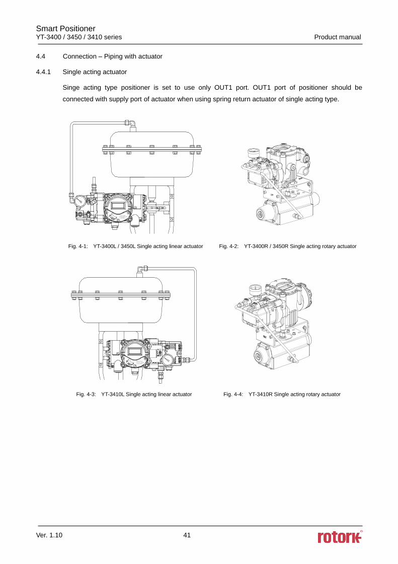
4.4.2 Double acting actuator
Double acting type positioner is set to use OUT1 and OUT2 port. As input signal increases, the
supply pressure will be supplied through OUT1 port.
Fig. 4-5: YT-3400R / 3450R Double acting linear actuator Fig. 4-6: YT-3400R / 3450R Double acting rotary actuator
Fig. 4-7: YT-3410R Double acting linear actuator Fig. 4-8: YT-3410R Double acting rotary actuator
Smart Positioner YT-3400 / 3450 / 3410 series Product manual
Ver. 1.10 43
5. Connection – Power
5.1 Safety
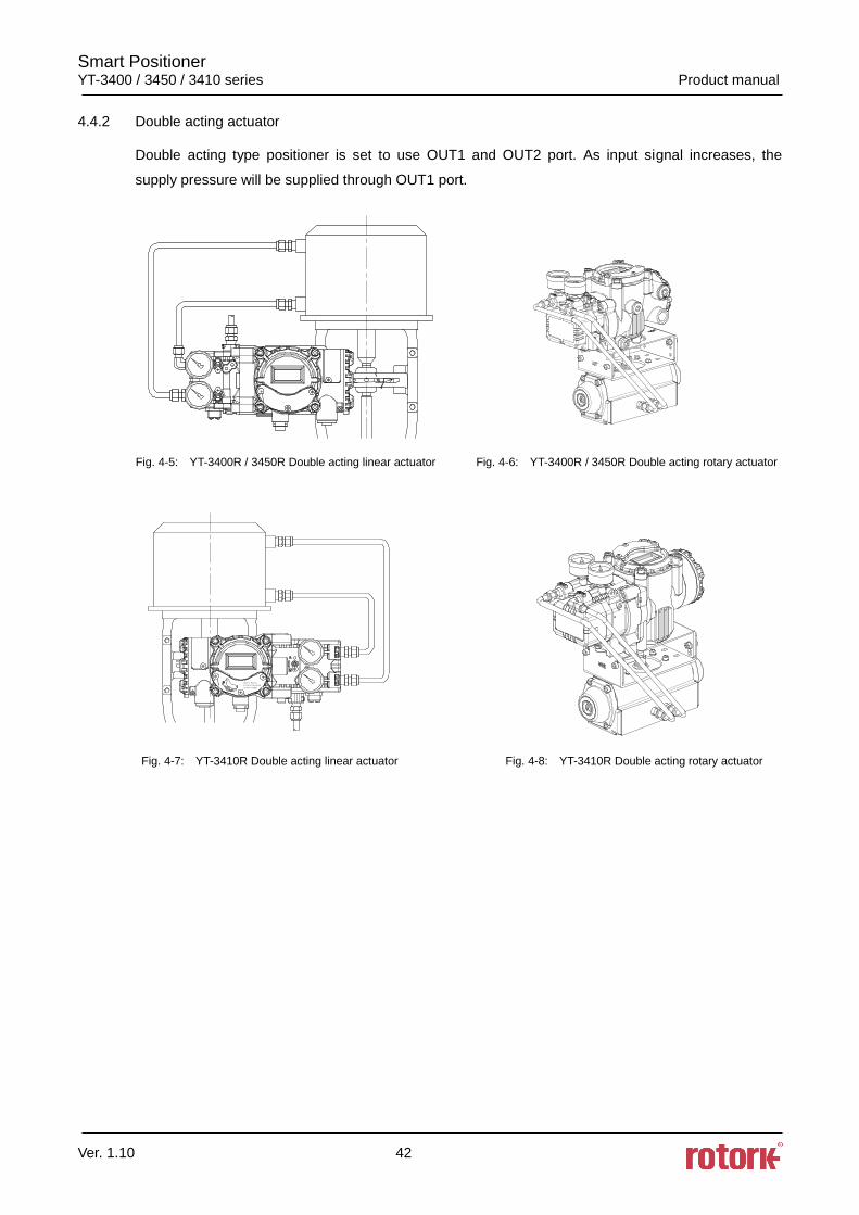
There are two conduit entries on the product. See “2.4 Product Code” for conduit entry threads.
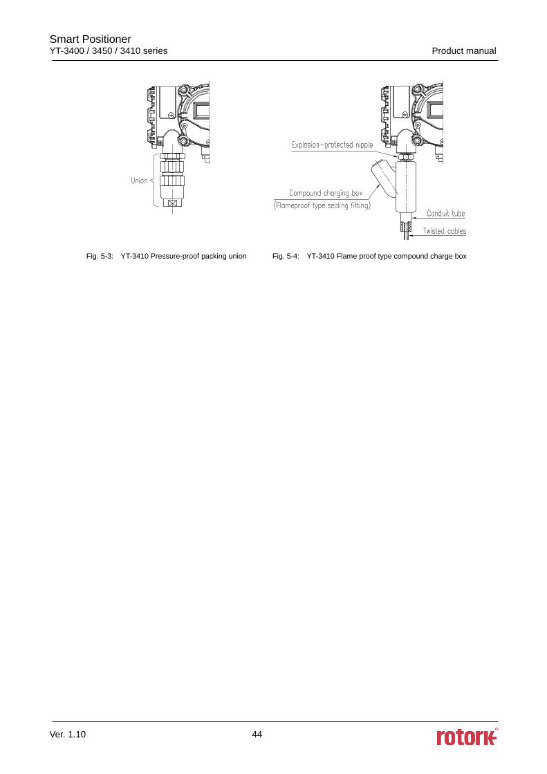
When installing in hazardous and explosive gas area, conduit tube or pressure-proof packing
union must be used. The compound charging box should be the flameproof type and must be
sealed completely.
Before connecting terminal, ensure that the power is off completely. Do not open the cover
when the power is still alive.
Please use ring terminal to protect against vibration or any other external impact.
Positioner usually uses 4~20mA DC. Minimum ampere of input signal of standard type positioner
is 3.2 mA and HART internal type positioner’s minimum ampere of input signal is 3.8 mA but
maximum ampere of input signal should be 24mA or under.
Compliance voltage of current source must be Min. 10V and Max. 28V. If the length of the supply
cable between the current source and the positioner is long, or if there is a filter or safety barrier,
then consider using a current source which could supply higher Compliance voltage.
Positioner with PTM options must be supplied with 9~28V DC separately. For L/S option
(transistor type), separate 24V DC (50mA) must be supplied.
DO NOT connect Voltage source (9~28V DC) to Input (4~20mA DC) terminal (IN+, IN-) as it will
cause PCB failure.
Positioner should be grounded.
Please use twisted cable with conductor section are 1.25mm2 and that is suitable for 600V
(complying with the conductor table of NEC Article 310). The outer diameter of the cable should
be between 6.35 ~ 10mm. Use shield wire to protect against electro-magnetic field and noise.
Please do not install the cable near high noise equipment, such as high-capacity transformer or
motor.
Fig. 5-1: YT-3400 / 3450 Pressure-proof packing union Fig. 5-2: YT-3400 / 3450 Flame proof type compound charge box
Smart Positioner YT-3400 / 3450 / 3410 series Product manual
Ver. 1.10 44
Fig. 5-3: YT-3410 Pressure-proof packing union Fig. 5-4: YT-3410 Flame proof type compound charge box
Smart Positioner YT-3400 / 3450 / 3410 series Product manual
Ver. 1.10 45
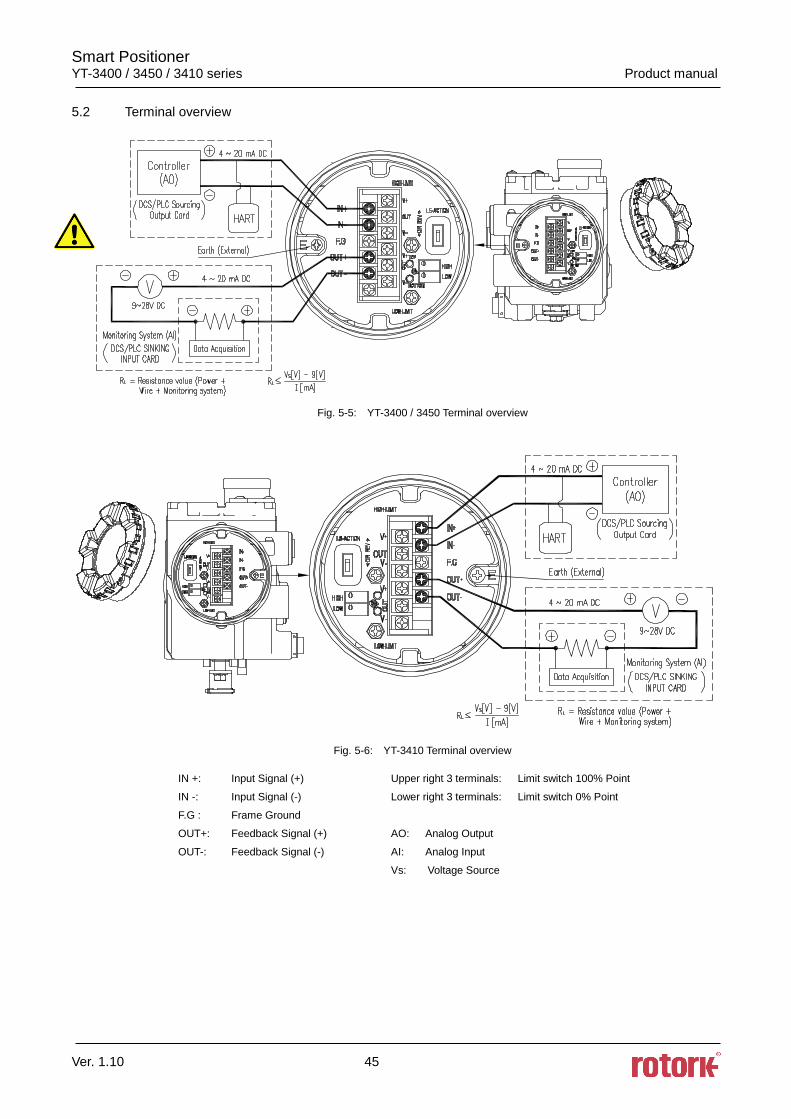
5.2 Terminal overview
Fig. 5-5: YT-3400 / 3450 Terminal overview
Fig. 5-6: YT-3410 Terminal overview
IN +: Input Signal (+) Upper right 3 terminals: Limit switch 100% Point
IN -: Input Signal (-) Lower right 3 terminals: Limit switch 0% Point
F.G : Frame Ground
OUT+: Feedback Signal (+) AO: Analog Output
OUT-: Feedback Signal (-) AI: Analog Input
Vs: Voltage Source
Smart Positioner YT-3400 / 3450 / 3410 series Product manual
Ver. 1.10 46
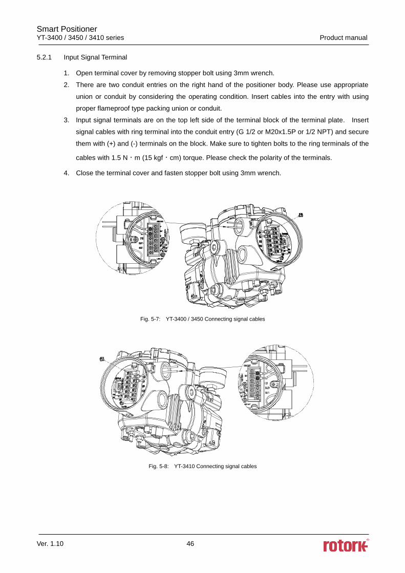
5.2.1 Input Signal Terminal
1. Open terminal cover by removing stopper bolt using 3mm wrench.
2. There are two conduit entries on the right hand of the positioner body. Please use appropriate
union or conduit by considering the operating condition. Insert cables into the entry with using
proper flameproof type packing union or conduit.
3. Input signal terminals are on the top left side of the terminal block of the terminal plate. Insert
signal cables with ring terminal into the conduit entry (G 1/2 or M20x1.5P or 1/2 NPT) and secure
them with (+) and (-) terminals on the block. Make sure to tighten bolts to the ring terminals of the
cables with 1.5 Nᆞm (15 kgfᆞcm) torque. Please check the polarity of the terminals.
4. Close the terminal cover and fasten stopper bolt using 3mm wrench.
Fig. 5-7: YT-3400 / 3450 Connecting signal cables
Fig. 5-8: YT-3410 Connecting signal cables
Smart Positioner YT-3400 / 3450 / 3410 series Product manual
Ver. 1.10 47
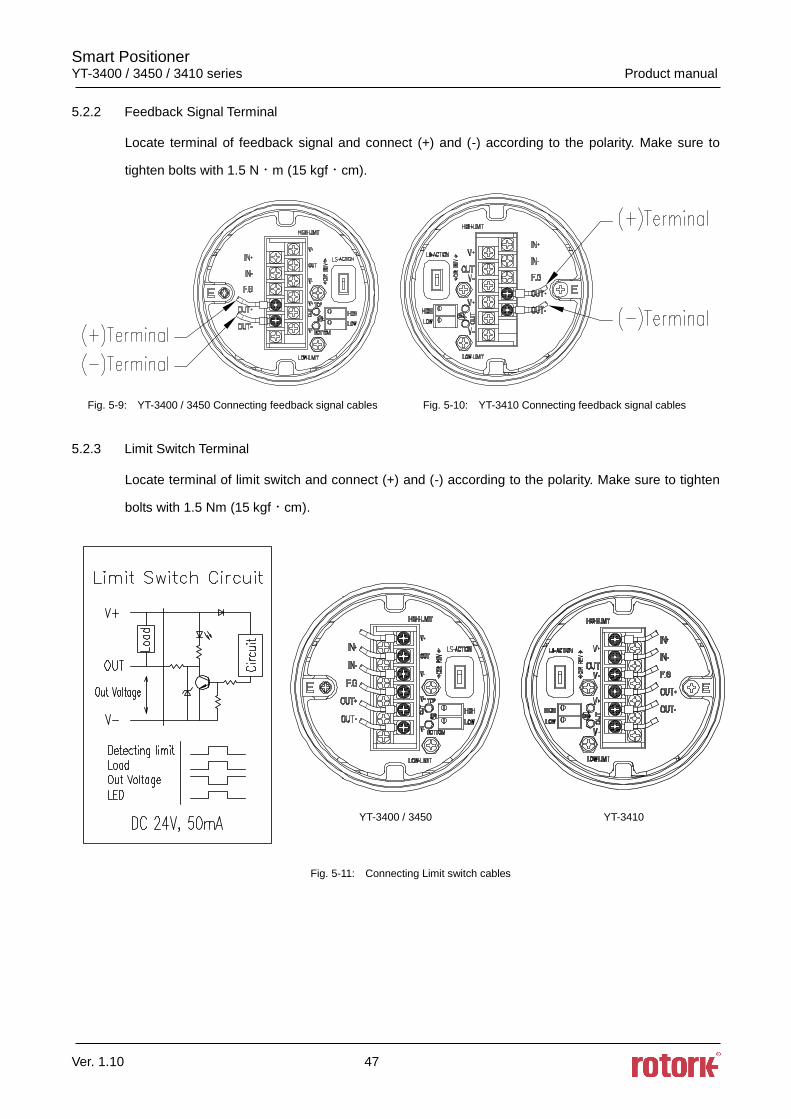
5.2.2 Feedback Signal Terminal
Locate terminal of feedback signal and connect (+) and (-) according to the polarity. Make sure to
tighten bolts with 1.5 Nᆞm (15 kgfᆞcm).
Fig. 5-9: YT-3400 / 3450 Connecting feedback signal cables Fig. 5-10: YT-3410 Connecting feedback signal cables
5.2.3 Limit Switch Terminal
Locate terminal of limit switch and connect (+) and (-) according to the polarity. Make sure to tighten
bolts with 1.5 Nm (15 kgfᆞcm).
YT-3400 / 3450 YT-3410
Fig. 5-11: Connecting Limit switch cables
Smart Positioner YT-3400 / 3450 / 3410 series Product manual
Ver. 1.10 48
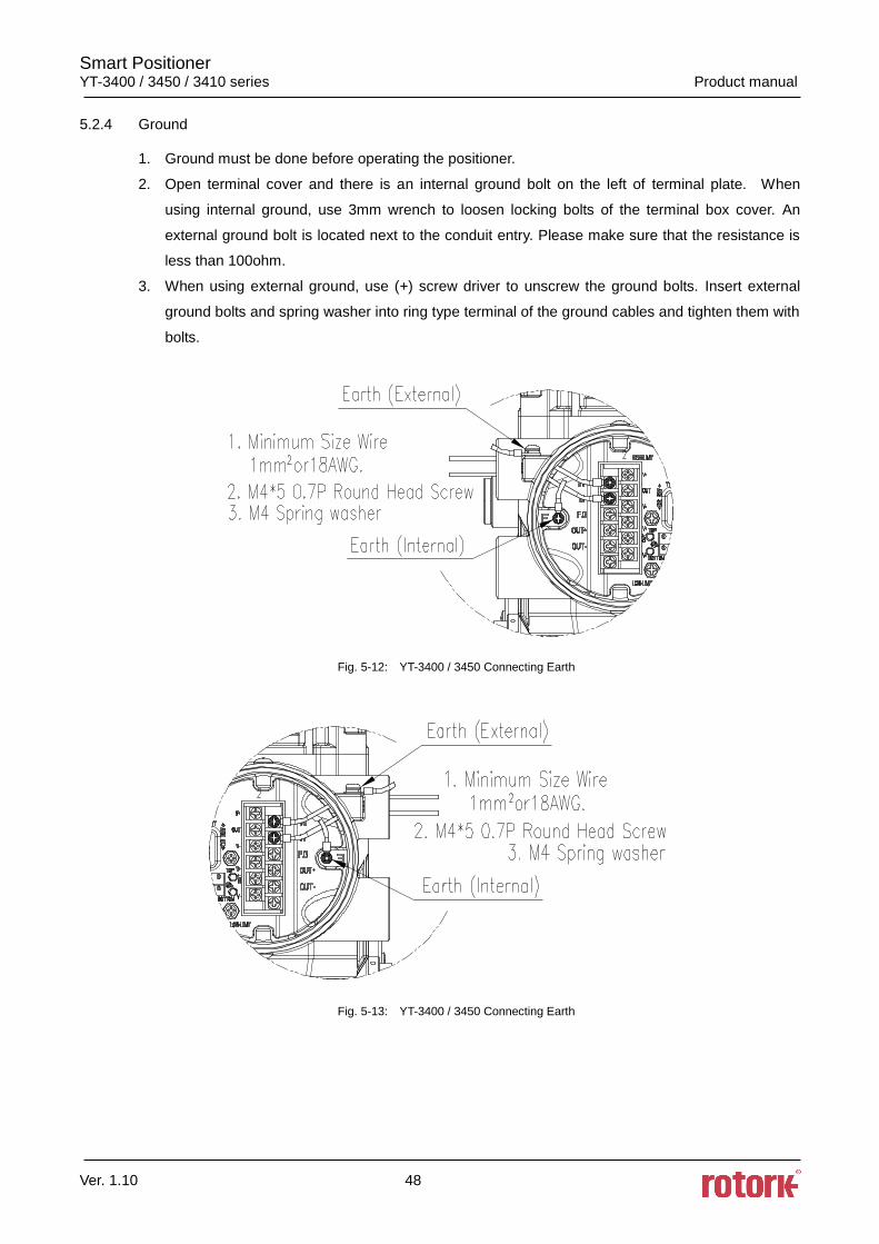
5.2.4 Ground
1. Ground must be done before operating the positioner.
2. Open terminal cover and there is an internal ground bolt on the left of terminal plate. When
using internal ground, use 3mm wrench to loosen locking bolts of the terminal box cover. An
external ground bolt is located next to the conduit entry. Please make sure that the resistance is
less than 100ohm.
3. When using external ground, use (+) screw driver to unscrew the ground bolts. Insert external
ground bolts and spring washer into ring type terminal of the ground cables and tighten them with
bolts.
Fig. 5-12: YT-3400 / 3450 Connecting Earth
Fig. 5-13: YT-3400 / 3450 Connecting Earth
Smart Positioner YT-3400 / 3450 / 3410 series Product manual
Ver. 1.10 49
6. Adjustments
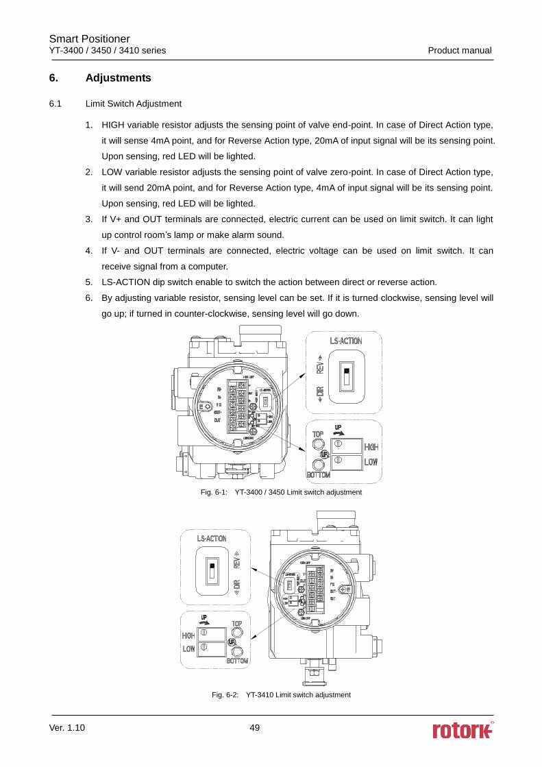
6.1 Limit Switch Adjustment
1. HIGH variable resistor adjusts the sensing point of valve end-point. In case of Direct Action type,
it will sense 4mA point, and for Reverse Action type, 20mA of input signal will be its sensing point.
Upon sensing, red LED will be lighted.
2. LOW variable resistor adjusts the sensing point of valve zero-point. In case of Direct Action type,
it will send 20mA point, and for Reverse Action type, 4mA of input signal will be its sensing point.
Upon sensing, red LED will be lighted.
3. If V+ and OUT terminals are connected, electric current can be used on limit switch. It can light
up control room’s lamp or make alarm sound.
4. If V- and OUT terminals are connected, electric voltage can be used on limit switch. It can
receive signal from a computer.
5. LS-ACTION dip switch enable to switch the action between direct or reverse action.
6. By adjusting variable resistor, sensing level can be set. If it is turned clockwise, sensing level will
go up; if turned in counter-clockwise, sensing level will go down.
Fig. 6-1: YT-3400 / 3450 Limit switch adjustment
Fig. 6-2: YT-3410 Limit switch adjustment
Smart Positioner YT-3400 / 3450 / 3410 series Product manual
Ver. 1.10 50
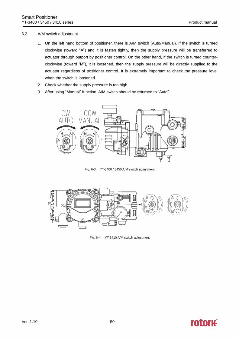
6.2 A/M switch adjustment
1. On the left hand bottom of positioner, there is A/M switch (Auto/Manual). If the switch is turned
clockwise (toward “A”) and it is fasten tightly, then the supply pressure will be transferred to
actuator through outport by positioner control. On the other hand, if the switch is turned counter-
clockwise (toward “M”), it is loosened, then the supply pressure will be directly supplied to the
actuator regardless of positioner control. It is extremely important to check the pressure level
when the switch is loosened
2. Check whether the supply pressure is too high.
3. After using “Manual” function, A/M switch should be returned to “Auto”.
Fig. 6-3: YT-3400 / 3450 A/M switch adjustment
Fig. 6-4: YT-3410 A/M switch adjustment
Smart Positioner YT-3400 / 3450 / 3410 series Product manual
Ver. 1.10 51
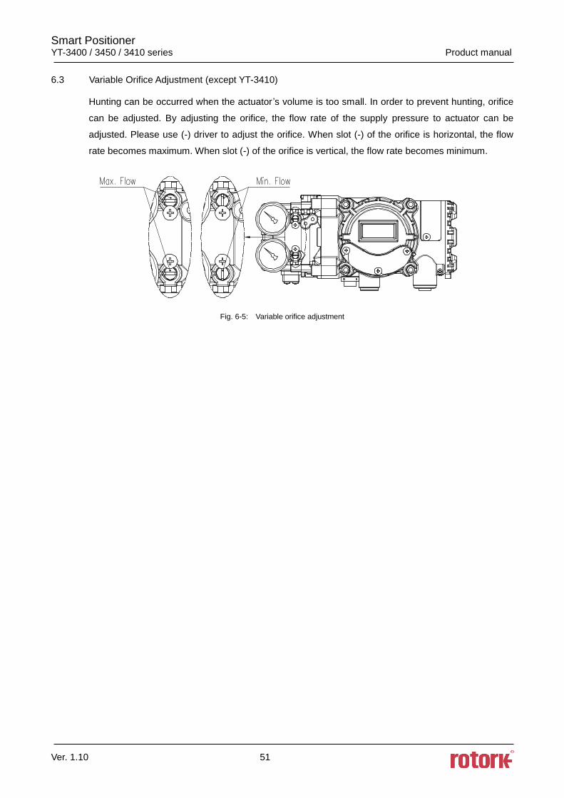
6.3 Variable Orifice Adjustment (except YT-3410)
Hunting can be occurred when the actuator ’s volume is too small. In order to prevent hunting, orifice
can be adjusted. By adjusting the orifice, the flow rate of the supply pressure to actuator can be
adjusted. Please use (-) driver to adjust the orifice. When slot (-) of the orifice is horizontal, the flow
rate becomes maximum. When slot (-) of the orifice is vertical, the flow rate becomes minimum.
Fig. 6-5: Variable orifice adjustment
Smart Positioner YT-3400 / 3450 / 3410 series Product manual
Ver. 1.10 52
7. Auto Calibration and PCB Operation
7.1 Warning
Following process will operate valve and actuator. Before proceeding with any Auto
Calibration, please separate valve from the entire system by using bypass valve, so Auto
Calibration will not affect entire valve process.
7.2 Button Description
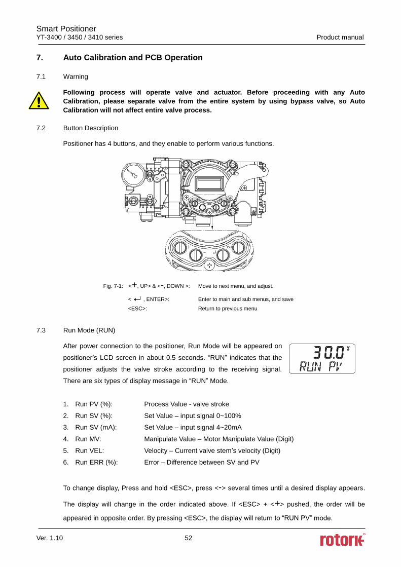
Positioner has 4 buttons, and they enable to perform various functions.
Fig. 7-1: <+, UP> & <-, DOWN >: Move to next menu, and adjust.
< , ENTER>: Enter to main and sub menus, and save
<ESC>: Return to previous menu
7.3 Run Mode (RUN)
After power connection to the positioner, Run Mode will be appeared on
positioner’s LCD screen in about 0.5 seconds. “RUN” indicates that the
positioner adjusts the valve stroke according to the receiving signal.
There are six types of display message in “RUN” Mode.
1. Run PV (%): Process Value - valve stroke
2. Run SV (%): Set Value – input signal 0~100%
3. Run SV (mA): Set Value – input signal 4~20mA
4. Run MV: Manipulate Value – Motor Manipulate Value (Digit)
5. Run VEL: Velocity – Current valve stem’s velocity (Digit)
6. Run ERR (%): Error – Difference between SV and PV
To change display, Press and hold <ESC>, press <-> several times until a desired display appears.
The display will change in the order indicated above. If <ESC> + <+> pushed, the order will be
appeared in opposite order. By pressing <ESC>, the display will return to “RUN PV” mode.
Smart Positioner YT-3400 / 3450 / 3410 series Product manual
Ver. 1.10 53
※ Please note that the screen will return to “RUN PV” mode if 100 seconds elapse from the
last button pressed.
※ By pressing <ESC> button several times from any MODES, it will return to “RUN PV” mode.
Therefore, if the users have entered into wrong modes by mistake or do not wish to proceed with
their current work, they could return to “RUN PV” mode.
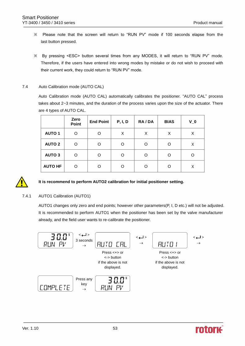
7.4 Auto Calibration mode (AUTO CAL)
Auto Calibration mode (AUTO CAL) automatically calibrates the positioner. “AUTO CAL” process
takes about 2~3 minutes, and the duration of the process varies upon the size of the actuator. There
are 4 types of AUTO CAL.
Zero Point
End Point P, I, D RA / DA BIAS V_0
AUTO 1 O O X X X X
AUTO 2 O O O O O X
AUTO 3 O O O O O O
AUTO HF O O O O O X
It is recommend to perform AUTO2 calibration for initial positioner setting.
7.4.1 AUTO1 Calibration (AUTO1)
AUTO1 changes only zero and end points; however other parameters(P, I, D etc.) will not be adjusted.
It is recommended to perform AUTO1 when the positioner has been set by the valve manufacturer
already, and the field user wants to re-calibrate the positioner.
3 seconds
Press <+> or
<-> button
if the above is not
displayed.
Press <+> or
<-> button
if the above is not
displayed.
Press any
key
Smart Positioner YT-3400 / 3450 / 3410 series Product manual
Ver. 1.10 54
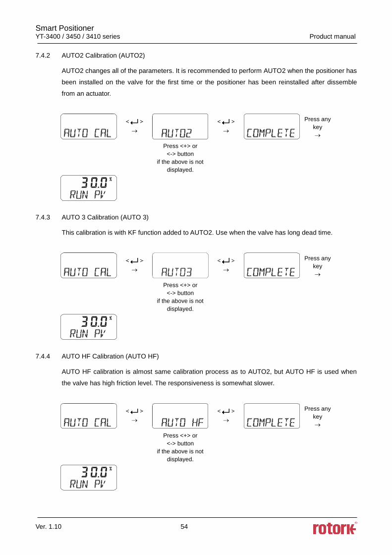
7.4.2 AUTO2 Calibration (AUTO2)
AUTO2 changes all of the parameters. It is recommended to perform AUTO2 when the positioner has
been installed on the valve for the first time or the positioner has been reinstalled after dissemble
from an actuator.
Press any
key
Press <+> or
<-> button
if the above is not
displayed.
7.4.3 AUTO 3 Calibration (AUTO 3)
This calibration is with KF function added to AUTO2. Use when the valve has long dead time.
Press any
key
Press <+> or
<-> button
if the above is not
displayed.
7.4.4 AUTO HF Calibration (AUTO HF)
AUTO HF calibration is almost same calibration process as to AUTO2, but AUTO HF is used when
the valve has high friction level. The responsiveness is somewhat slower.
Press any
key
Press <+> or
<-> button
if the above is not
displayed.
Smart Positioner YT-3400 / 3450 / 3410 series Product manual
Ver. 1.10 55
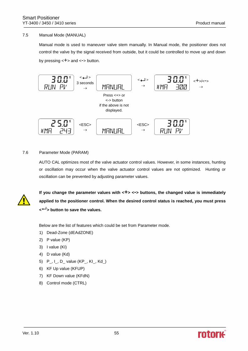
7.5 Manual Mode (MANUAL)
Manual mode is used to maneuver valve stem manually. In Manual mode, the positioner does not
control the valve by the signal received from outside, but it could be controlled to move up and down
by pressing <+> and <-> button.
3 seconds
<+>/<->
Press <+> or
<-> button
if the above is not
displayed.
<ESC>
<ESC>
7.6 Parameter Mode (PARAM)
AUTO CAL optimizes most of the valve actuator control values. However, in some instances, hunting
or oscillation may occur when the valve actuator control values are not optimized. Hunting or
oscillation can be prevented by adjusting parameter values.
If you change the parameter values with <+> <-> buttons, the changed value is immediately
applied to the positioner control. When the desired control status is reached, you must press
< > button to save the values.
Below are the list of features which could be set from Parameter mode.
1) Dead-Zone (dEAdZONE)
2) P value (KP)
3) I value (KI)
4) D value (Kd)
5) P_, I_, D_ value (KP_, KI_, Kd_)
6) KF Up value (KFUP)
7) KF Down value (KFdN)
8) Control mode (CTRL)
Smart Positioner YT-3400 / 3450 / 3410 series Product manual
Ver. 1.10 56
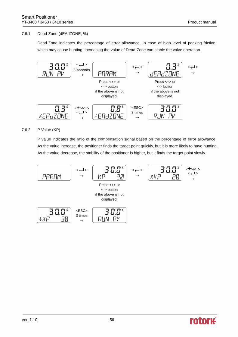
7.6.1 Dead-Zone (dEAdZONE, %)
Dead-Zone indicates the percentage of error allowance. In case of high level of packing friction,
which may cause hunting, increasing the value of Dead-Zone can stable the valve operation.
3 seconds
Press <+> or
<-> button
if the above is not
displayed.
Press <+> or
<-> button
if the above is not
displayed.
<+>/<->
<ESC>
3 times
7.6.2 P Value (KP)
P value indicates the ratio of the compensation signal based on the percentage of error allowance.
As the value increase, the positioner finds the target point quickly, but it is more likely to have hunting.
As the value decrease, the stability of the positioner is higher, but it finds the target point slowly.
<+>/<->
Press <+> or
<-> button
if the above is not
displayed.
<ESC>
3 times
Smart Positioner YT-3400 / 3450 / 3410 series Product manual
Ver. 1.10 57
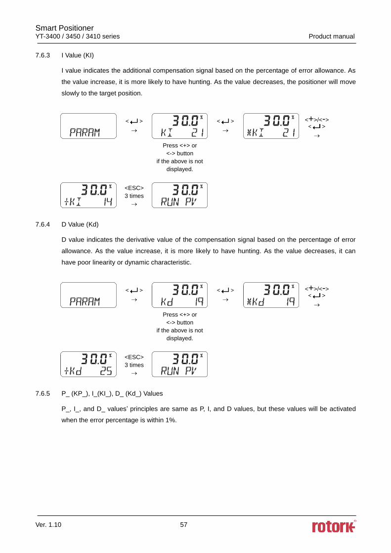
7.6.3 I Value (KI)
I value indicates the additional compensation signal based on the percentage of error allowance. As
the value increase, it is more likely to have hunting. As the value decreases, the positioner will move
slowly to the target position.
<+>/<->
Press <+> or
<-> button
if the above is not
displayed.
<ESC>
3 times
7.6.4 D Value (Kd)
D value indicates the derivative value of the compensation signal based on the percentage of error
allowance. As the value increase, it is more likely to have hunting. As the value decreases, it can
have poor linearity or dynamic characteristic.
<+>/<->
Press <+> or
<-> button
if the above is not
displayed.
<ESC>
3 times
7.6.5 P_ (KP_), I_(KI_), D_ (Kd_) Values
P_, I_, and D_ values’ principles are same as P, I, and D values, but these values will be activated
when the error percentage is within 1%.
Smart Positioner YT-3400 / 3450 / 3410 series Product manual
Ver. 1.10 58
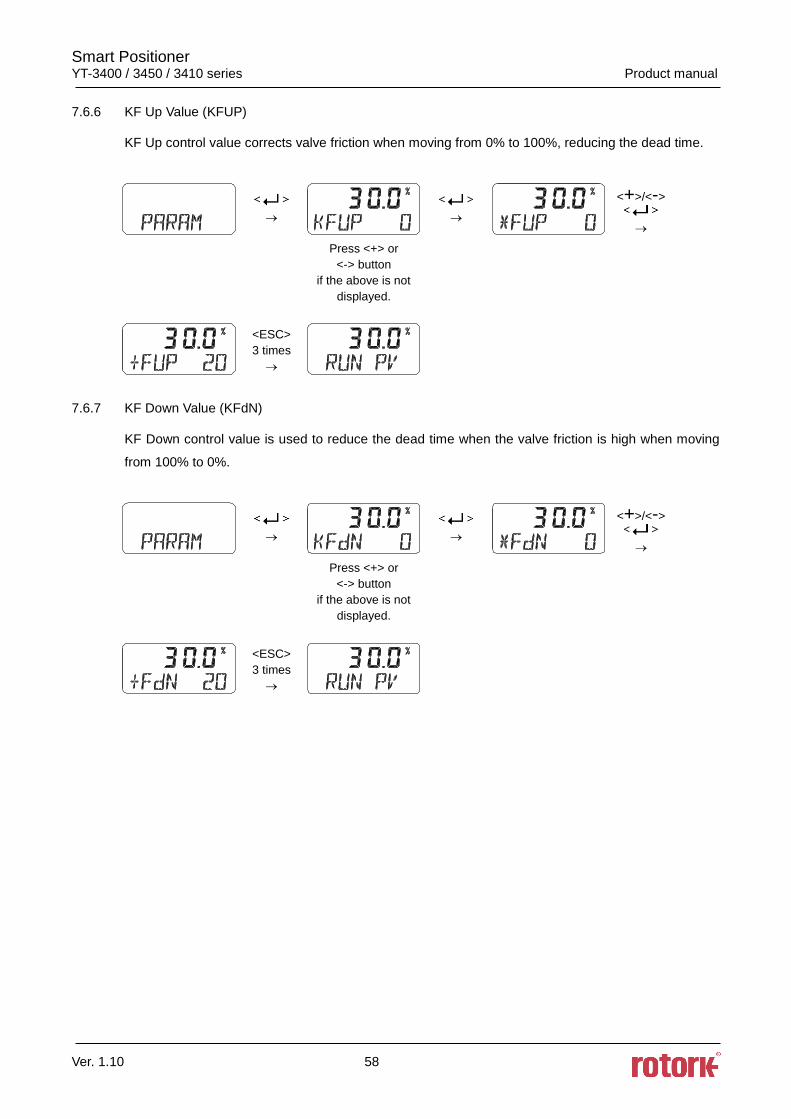
7.6.6 KF Up Value (KFUP)
KF Up control value corrects valve friction when moving from 0% to 100%, reducing the dead time.
<+>/<->
Press <+> or
<-> button
if the above is not
displayed.
<ESC>
3 times
7.6.7 KF Down Value (KFdN)
KF Down control value is used to reduce the dead time when the valve friction is high when moving
from 100% to 0%.
<+>/<->
Press <+> or
<-> button
if the above is not
displayed.
<ESC>
3 times
Smart Positioner YT-3400 / 3450 / 3410 series Product manual
Ver. 1.10 59
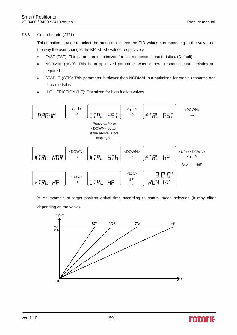
7.6.8 Control mode (CTRL)
This function is used to select the menu that stores the PID values corresponding to the valve, not
the way the user changes the KP, KI, KD values respectively..
• FAST (FST): This parameter is optimized for fast response characteristics. (Default)
• NORMAL (NOR): This is an optimized parameter when general response characteristics are
required..
• STABLE (STb): This parameter is slower than NORMAL but optimized for stable response and
characteristics.
• HIGH FRICTION (HF): Optimized for high friction valves.
<DOWN>
Press <UP> or
<DOWN> button
if the above is not
displayed.
<DOWN>
<DOWN>
<UP>/<DOWN>
Save as HdF.
<ESC>
<ESC>
3번
※ An example of target position arrival time according to control mode selection (It may differ
depending on the valve).
Smart Positioner YT-3400 / 3450 / 3410 series Product manual
Ver. 1.10 60
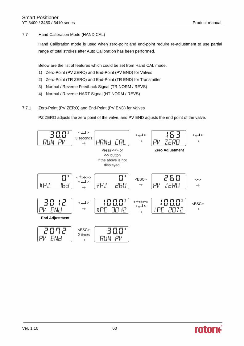
7.7 Hand Calibration Mode (HAND CAL)
Hand Calibration mode is used when zero-point and end-point require re-adjustment to use partial
range of total strokes after Auto Calibration has been performed.
Below are the list of features which could be set from Hand CAL mode.
1) Zero-Point (PV ZERO) and End-Point (PV END) for Valves
2) Zero-Point (TR ZERO) and End-Point (TR END) for Transmitter
3) Normal / Reverse Feedback Signal (TR NORM / REVS)
4) Normal / Reverse HART Signal (HT NORM / REVS)
7.7.1 Zero-Point (PV ZERO) and End-Point (PV END) for Valves
PZ ZERO adjusts the zero point of the valve, and PV END adjusts the end point of the valve.
3 seconds
Press <+> or
<-> button
if the above is not
displayed.
Zero Adjustment
<+>/<->
<ESC>
<->
<+>/<->
<ESC>
End Adjustment
<ESC>
2 times
Smart Positioner YT-3400 / 3450 / 3410 series Product manual
Ver. 1.10 61
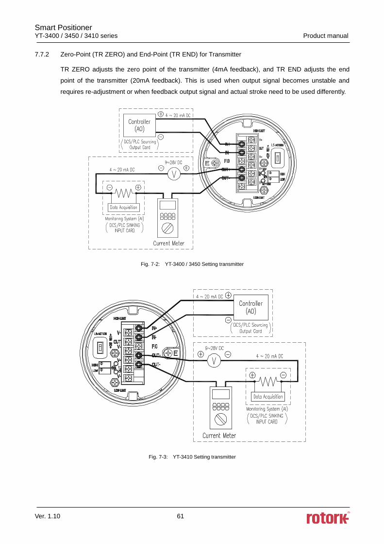
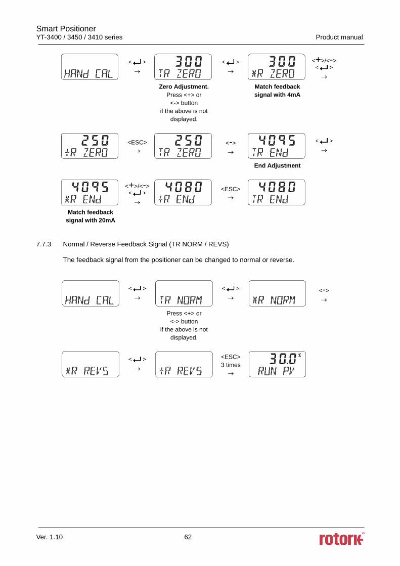
7.7.2 Zero-Point (TR ZERO) and End-Point (TR END) for Transmitter
TR ZERO adjusts the zero point of the transmitter (4mA feedback), and TR END adjusts the end
point of the transmitter (20mA feedback). This is used when output signal becomes unstable and
requires re-adjustment or when feedback output signal and actual stroke need to be used differently.
Fig. 7-2: YT-3400 / 3450 Setting transmitter
Fig. 7-3: YT-3410 Setting transmitter
Smart Positioner YT-3400 / 3450 / 3410 series Product manual
Ver. 1.10 62
<+>/<->
Zero Adjustment.
Press <+> or
<-> button
if the above is not
displayed.
Match feedback
signal with 4mA
<ESC>
<->
End Adjustment
<+>/<->
<ESC>
Match feedback
signal with 20mA
7.7.3 Normal / Reverse Feedback Signal (TR NORM / REVS)
The feedback signal from the positioner can be changed to normal or reverse.
<->
Press <+> or
<-> button
if the above is not
displayed.
<ESC>
3 times
Smart Positioner YT-3400 / 3450 / 3410 series Product manual
Ver. 1.10 63
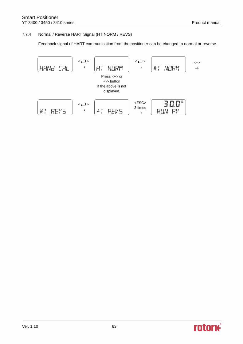
7.7.4 Normal / Reverse HART Signal (HT NORM / REVS)
Feedback signal of HART communication from the positioner can be changed to normal or reverse.
<->
Press <+> or
<-> button
if the above is not
displayed.
<ESC>
3 times
Smart Positioner YT-3400 / 3450 / 3410 series Product manual
Ver. 1.10 64
7.8 Valve Mode (VALVE)
Valve mode offers useful and various function settings for operating the control valve.
Below are the list of functions which could be set from Valve mode.
1) Acting Adjustment (ACT RA / dA)
2) Characteristic Adjustment (CHAR)
3) User Characteristics (USER SET)
4) Tight Shut Open (TSHUT OP)
5) Tight Shut Close (TSHUT CL)
6) Split Range Mode (SPLIT)
7) Custom Zero Setting Mode of Split Range (CST ZERO)
8) Custom End Setting Mode of Split Range (CST ENd)
9) Interpolation Mode (ITP ON / OFF)
10) Acting Type (SINGLE / dOUBLE)
11) Lever Type (STd / AdT)
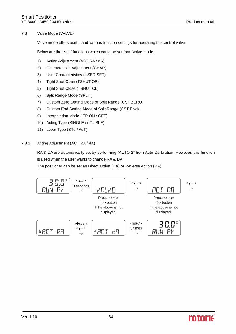
7.8.1 Acting Adjustment (ACT RA / dA)
RA & DA are automatically set by performing “AUTO 2” from Auto Calibration. However, this function
is used when the user wants to change RA & DA.
The positioner can be set as Direct Action (DA) or Reverse Action (RA).
3 seconds
Press <+> or
<-> button
if the above is not
displayed.
Press <+> or
<-> button
if the above is not
displayed.
<+>/<->
<ESC>
3 times
Smart Positioner YT-3400 / 3450 / 3410 series Product manual
Ver. 1.10 65
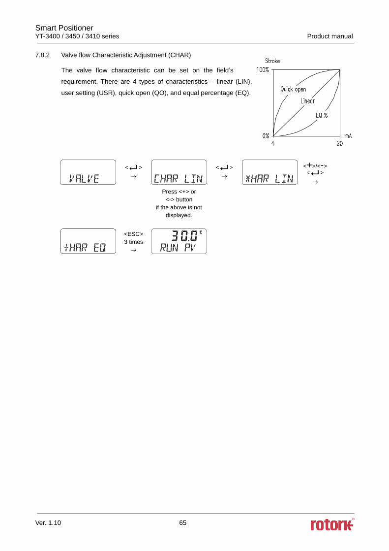
7.8.2 Valve flow Characteristic Adjustment (CHAR)
The valve flow characteristic can be set on the field’s
requirement. There are 4 types of characteristics – linear (LIN),
user setting (USR), quick open (QO), and equal percentage (EQ).
<+>/<->
Press <+> or
<-> button
if the above is not
displayed.
<ESC>
3 times
Smart Positioner YT-3400 / 3450 / 3410 series Product manual
Ver. 1.10 66
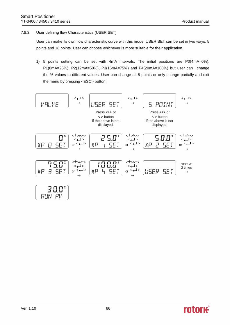
7.8.3 User defining flow Characteristics (USER SET)
User can make its own flow characteristic curve with this mode. USER SET can be set in two ways, 5
points and 18 points. User can choose whichever is more suitable for their application.
1) 5 points setting can be set with 4mA intervals. The initial positions are P0(4mA=0%),
P1(8mA=25%), P2(12mA=50%), P3(16mA=75%) and P4(20mA=100%) but user can change
the % values to different values. User can change all 5 points or only change partially and exit
the menu by pressing <ESC> button.
Press <+> or
<-> button if the above is not
displayed.
Press <+> or
<-> button if the above is not
displayed.
<+>/<->
or
<+>/<->
or
<+>/<->
or
<+>/<->
or
<+>/<->
or
<ESC> 2 times
Smart Positioner YT-3400 / 3450 / 3410 series Product manual
Ver. 1.10 67
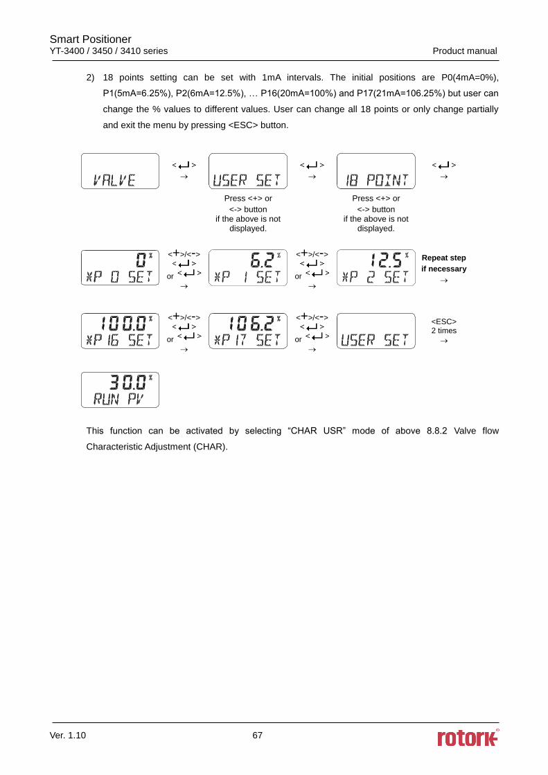
2) 18 points setting can be set with 1mA intervals. The initial positions are P0(4mA=0%),
P1(5mA=6.25%), P2(6mA=12.5%), … P16(20mA=100%) and P17(21mA=106.25%) but user can
change the % values to different values. User can change all 18 points or only change partially
and exit the menu by pressing <ESC> button.
Press <+> or
<-> button if the above is not
displayed.
Press <+> or
<-> button if the above is not
displayed.
<+>/<->
or
<+>/<->
or
Repeat step
if necessary
<+>/<->
or
<+>/<->
or
<ESC> 2 times
This function can be activated by selecting “CHAR USR” mode of above 8.8.2 Valve flow
Characteristic Adjustment (CHAR).
Smart Positioner YT-3400 / 3450 / 3410 series Product manual
Ver. 1.10 68
7.8.4 Tight Shut Open (TSHUT OP)
Tight shut open shows the current value in percentage (%). Input current of 4mA is 0%, 20mA is
100%. If temporary Tight shut open value (≤100%) is set and input current value is above the set %
value, the valve’s position is immediately moved to 100%. For example, if linear actuator is used and
the valve’s closing direction is 100% and input value of the current is above Tight shut open set value,
the set pressure from the regulator will be transferred to the actuator which will enhance the power to
close the valve and keep it from any leakage.
<+>/<->
Press <+> or
<-> button
if the above is not
displayed.
<ESC>
3 times
7.8.5 Tight Shut Close (TSHUT CL)
Tight shut close shows the current value in percentage (%). Input current of 4mA is 0%, 20mA is
100%. If temporary Tight shut close value (≤100%) is set and input current value is below the set %
value, the valve’s position is immediately moved to 0%. For example, if rotary actuator is used and
the valve’s closing direction is 0% and input value of the current is above Tight shut open set value, it
will release all the remaining pressure from Out1 of the actuator which will have the return spring
power of the actuator or Out2 pressure to close the valve and keep it from any leakage.
<+>/<->
Press <+> or
<-> button
if the above is not
displayed.
<ESC>
3 times

Smart Positioner YT-3400 / 3450 / 3410 series Product manual
Ver. 1.10 69
7.8.6 Split Range Mode (SPLIT)
The valve can be operated in full stroke by split range control of input signal as 4~12mA or 12~20mA.
<+>/<->
Press <+> or
<-> button
if the above is not
displayed.
4~20mA Control
<ESC>
3 times
4~12mA Control
7.8.7 Custom Zero Setting Mode of Split Range (CST ZERO)
From the initial 4~20mA control settings of valve stroke from 0~100%, this mode allows the user to
change the zero point to (≥4) mA instead of 4mA.
For example, the user could change the control settings of the valve stroke from 4~20mA to 7~20mA
for 0~100% stroke.
However, please note that the “Zero” and “End” points’ deviation current value must be above
4mA.
<+>/<->
Press <+> or
<-> button
if the above is not
displayed.
<ESC>
3 times
Smart Positioner YT-3400 / 3450 / 3410 series Product manual
Ver. 1.10 70
7.8.8 Custom End Setting Mode of Split Range (CST ENd)
From the initial 4~20mA control settings of valve stroke from 0~100%, this mode allows the user to
change the end point to (≤20) mA instead of 20mA.
For example, the user could change the control settings of the valve stroke from 4~20mA to 4~16mA
for 0~100% stroke.
However, please note that the “Zero” and “End” points’ deviation current value must be above
4mA.
<+>/<->
Press <+> or
<-> button
if the above is not
displayed.
<ESC>
3 times
7.8.9 Interpolation Mode (ITP ON/OFF, ITP USER SET)
In case of linear positioner, the error of accuracy occurs when the linear motion of actuator changes
into the rotary motion of feedback lever. After the auto calibration, the positioner turns on ITP function
with an appropriate value of interpolation automatically. The user can manually turn on or off the ITP
function, also can set any value of the interpolation. (in ITP USER mode)
※ The below shows that the user manually change ITP ON into OFF.
<->
Press <+> or
<-> button
if the above is not
displayed.
<ESC>
3 times
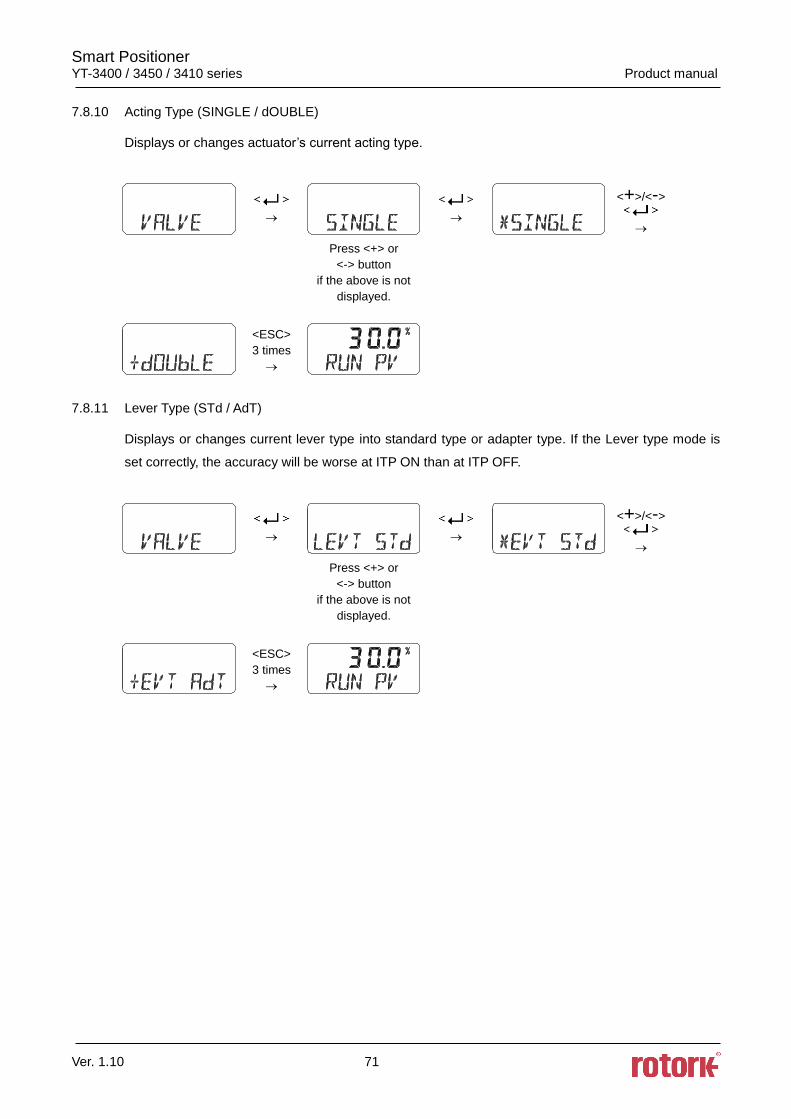
Smart Positioner YT-3400 / 3450 / 3410 series Product manual
Ver. 1.10 71
7.8.10 Acting Type (SINGLE / dOUBLE)
Displays or changes actuator’s current acting type.
<+>/<->
Press <+> or
<-> button
if the above is not
displayed.
<ESC>
3 times
7.8.11 Lever Type (STd / AdT)
Displays or changes current lever type into standard type or adapter type. If the Lever type mode is
set correctly, the accuracy will be worse at ITP ON than at ITP OFF.
<+>/<->
Press <+> or
<-> button
if the above is not
displayed.
<ESC>
3 times
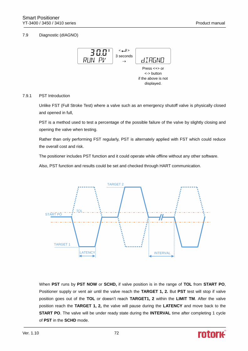
Smart Positioner YT-3400 / 3450 / 3410 series Product manual
Ver. 1.10 72
7.9 Diagnostic (dIAGNO)
3 seconds
Press <+> or
<-> button
if the above is not
displayed.
7.9.1 PST Introduction
Unlike FST (Full Stroke Test) where a valve such as an emergency shutoff valve is physically closed
and opened in full,
PST is a method used to test a percentage of the possible failure of the valve by slightly closing and
opening the valve when testing.
Rather than only performing FST regularly, PST is alternately applied with FST which could reduce
the overall cost and risk.
The positioner includes PST function and it could operate while offline without any other software.
Also, PST function and results could be set and checked through HART communication.
When PST runs by PST NOW or SCHD, if valve position is in the range of TOL from START PO,
Positioner supply or vent air until the valve reach the TARGET 1, 2. But PST test will stop if valve
position goes out of the TOL or doesn’t reach TARGET1, 2 within the LIMIT TM. After the valve
position reach the TARGET 1, 2, the valve will pause during the LATENCY and move back to the
START PO. The valve will be under ready state during the INTERVAL time after completing 1 cycle
of PST in the SCHD mode.
TOL
START PO
TARGET 1
TARGET 2
LATENCY
INTERVAL
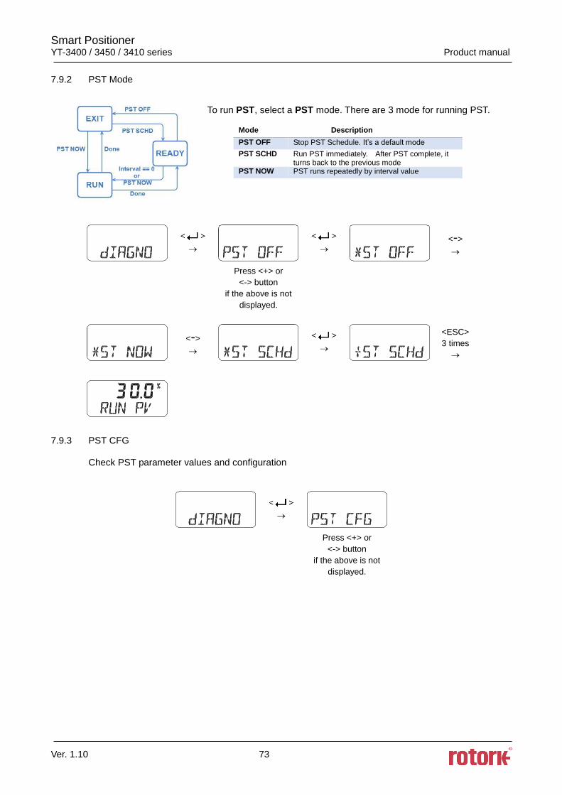
Smart Positioner YT-3400 / 3450 / 3410 series Product manual
Ver. 1.10 73
7.9.2 PST Mode
To run PST, select a PST mode. There are 3 mode for running PST.
<->
Press <+> or
<-> button
if the above is not
displayed.
<->
<ESC>
3 times
7.9.3 PST CFG
Check PST parameter values and configuration
Press <+> or
<-> button
if the above is not
displayed.
Mode Description
PST OFF Stop PST Schedule. It’s a default mode
PST SCHD Run PST immediately. After PST complete, it turns back to the previous mode
PST NOW PST runs repeatedly by interval value
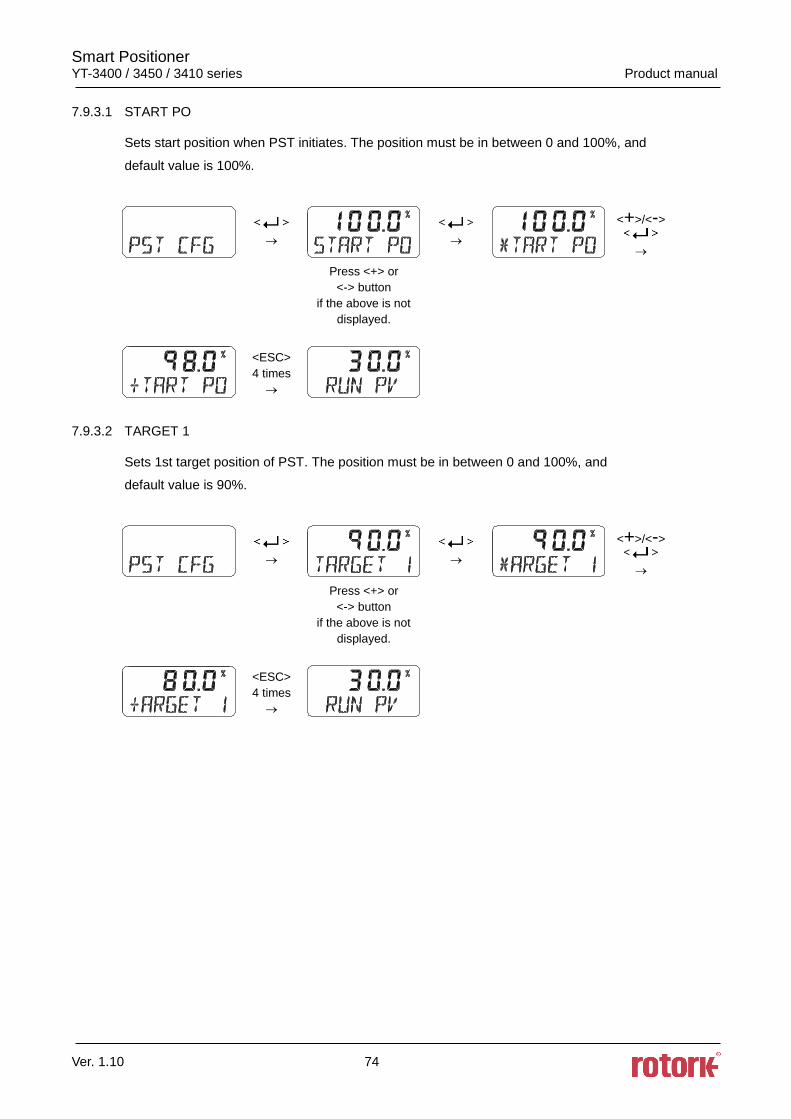
Smart Positioner YT-3400 / 3450 / 3410 series Product manual
Ver. 1.10 74
7.9.3.1 START PO
Sets start position when PST initiates. The position must be in between 0 and 100%, and
default value is 100%.
<+>/<->
Press <+> or
<-> button
if the above is not
displayed.
<ESC>
4 times
7.9.3.2 TARGET 1
Sets 1st target position of PST. The position must be in between 0 and 100%, and
default value is 90%.
<+>/<->
Press <+> or
<-> button
if the above is not
displayed.
<ESC>
4 times
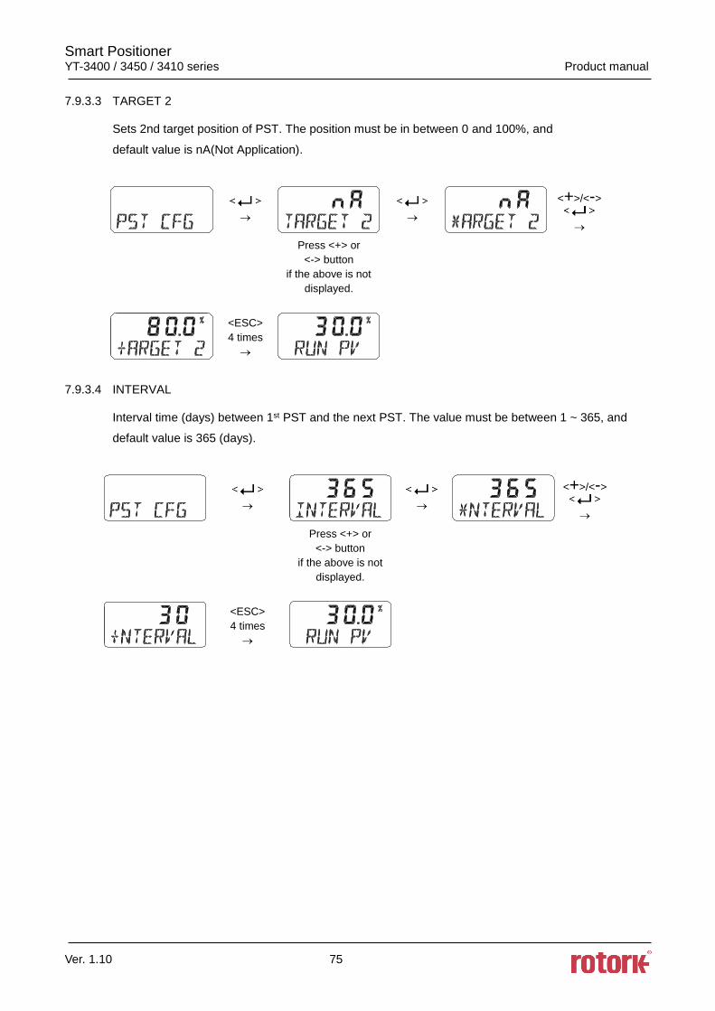
Smart Positioner YT-3400 / 3450 / 3410 series Product manual
Ver. 1.10 75
7.9.3.3 TARGET 2
Sets 2nd target position of PST. The position must be in between 0 and 100%, and
default value is nA(Not Application).
<+>/<->
Press <+> or
<-> button
if the above is not
displayed.
<ESC>
4 times
7.9.3.4 INTERVAL
Interval time (days) between 1st PST and the next PST. The value must be between 1 ~ 365, and
default value is 365 (days).
<+>/<->
Press <+> or
<-> button
if the above is not
displayed.
<ESC>
4 times
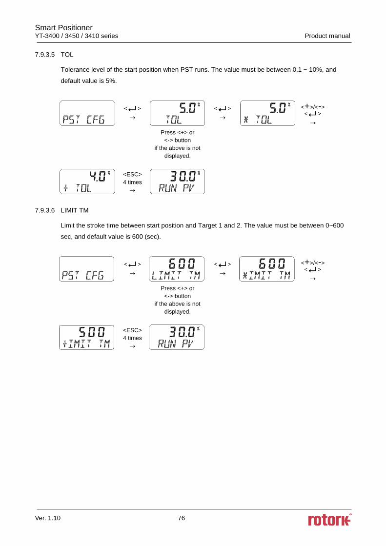
Smart Positioner YT-3400 / 3450 / 3410 series Product manual
Ver. 1.10 76
7.9.3.5 TOL
Tolerance level of the start position when PST runs. The value must be between 0.1 ~ 10%, and
default value is 5%.
<+>/<->
Press <+> or
<-> button
if the above is not
displayed.
<ESC>
4 times
7.9.3.6 LIMIT TM
Limit the stroke time between start position and Target 1 and 2. The value must be between 0~600
sec, and default value is 600 (sec).
<+>/<->
Press <+> or
<-> button
if the above is not
displayed.
<ESC>
4 times
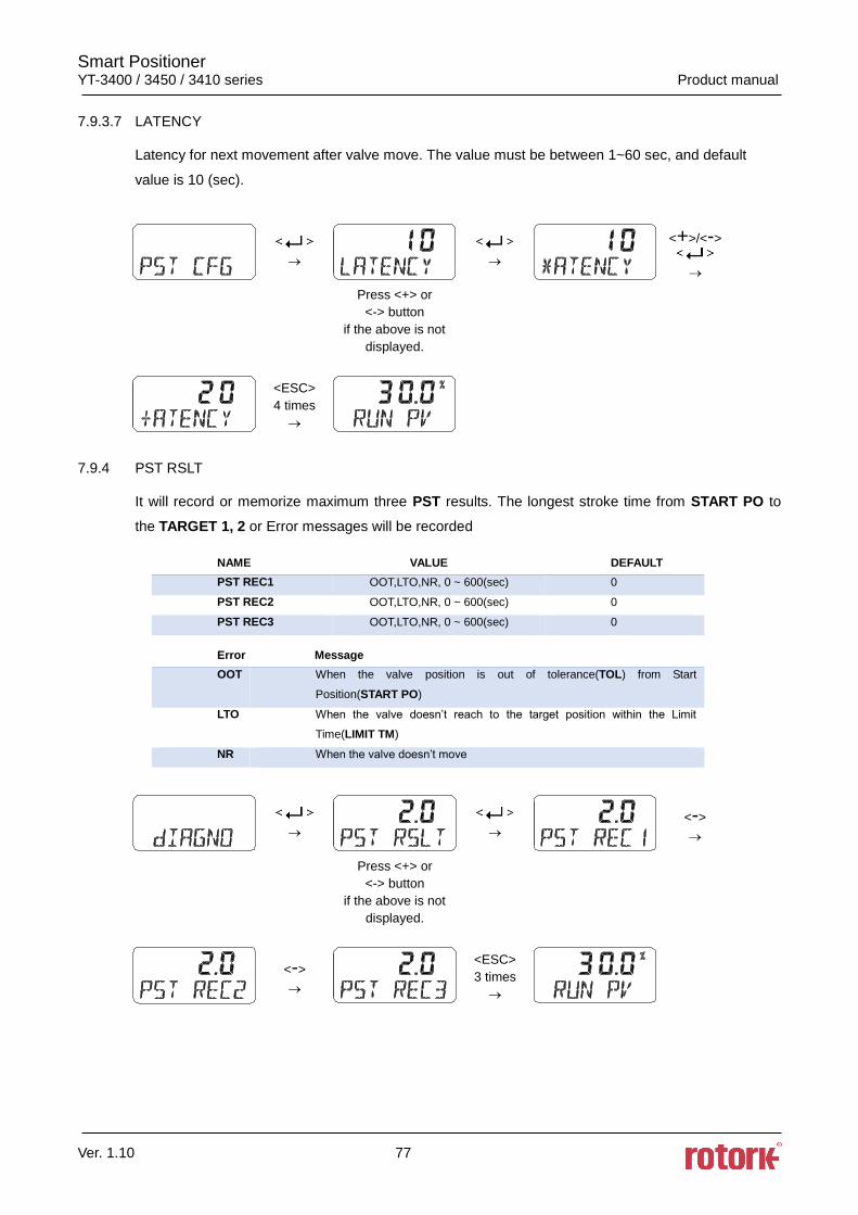
Smart Positioner YT-3400 / 3450 / 3410 series Product manual
Ver. 1.10 77
7.9.3.7 LATENCY
Latency for next movement after valve move. The value must be between 1~60 sec, and default
value is 10 (sec).
<+>/<->
Press <+> or
<-> button
if the above is not
displayed.
<ESC>
4 times
7.9.4 PST RSLT
It will record or memorize maximum three PST results. The longest stroke time from START PO to
the TARGET 1, 2 or Error messages will be recorded
NAME VALUE DEFAULT
PST REC1 OOT,LTO,NR, 0 ~ 600(sec) 0
PST REC2 OOT,LTO,NR, 0 ~ 600(sec) 0
PST REC3 OOT,LTO,NR, 0 ~ 600(sec) 0
Error Message
OOT When the valve position is out of tolerance(TOL) from Start
Position(START PO)
LTO When the valve doesn’t reach to the target position within the Limit
Time(LIMIT TM)
NR When the valve doesn’t move
<->
Press <+> or
<-> button
if the above is not
displayed.
<->
<ESC>
3 times
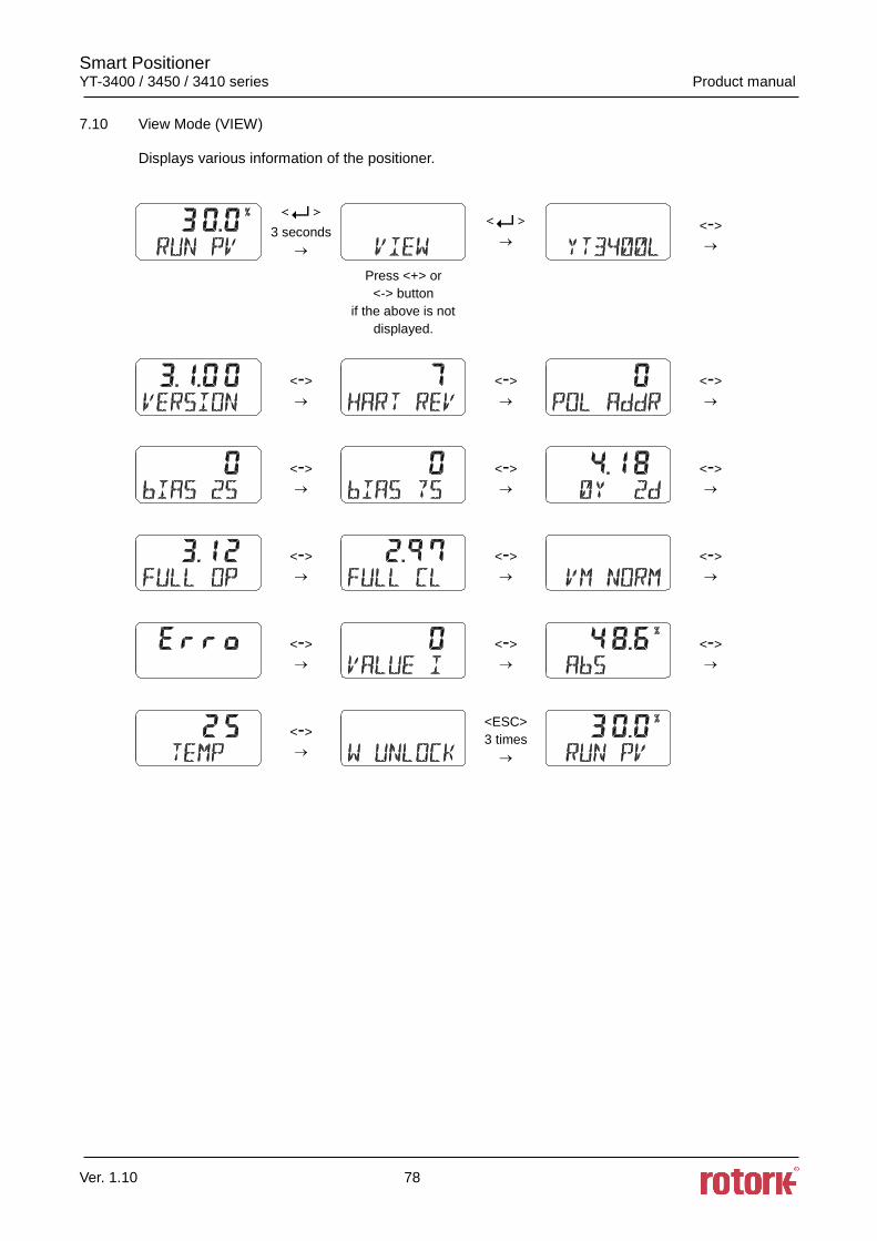
Smart Positioner YT-3400 / 3450 / 3410 series Product manual
Ver. 1.10 78
7.10 View Mode (VIEW)
Displays various information of the positioner.
3 seconds
<->
Press <+> or
<-> button
if the above is not
displayed.
<->
<->
<->
<->
<->
<->
<->
<->
<->
<->
<->
<->
<->
<ESC>
3 times
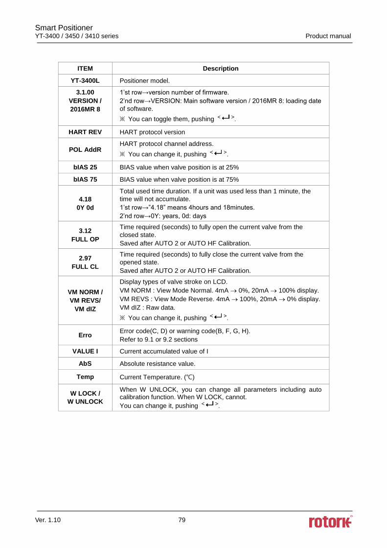
Smart Positioner YT-3400 / 3450 / 3410 series Product manual
Ver. 1.10 79
ITEM Description
YT-3400L Positioner model.
3.1.00
VERSION /
2016MR 8
1’st row→version number of firmware.
2’nd row→VERSION: Main software version / 2016MR 8: loading date
of software.
※ You can toggle them, pushing .
HART REV HART protocol version
POL AddR HART protocol channel address.
※ You can change it, pushing .
bIAS 25 BIAS value when valve position is at 25%
bIAS 75 BIAS value when valve position is at 75%
4.18
0Y 0d
Total used time duration. If a unit was used less than 1 minute, the
time will not accumulate.
1’st row→”4.18” means 4hours and 18minutes.
2’nd row→0Y: years, 0d: days
3.12
FULL OP
Time required (seconds) to fully open the current valve from the
closed state.
Saved after AUTO 2 or AUTO HF Calibration.
2.97
FULL CL
Time required (seconds) to fully close the current valve from the
opened state.
Saved after AUTO 2 or AUTO HF Calibration.
VM NORM /
VM REVS/
VM dIZ
Display types of valve stroke on LCD.
VM NORM : View Mode Normal. 4mA 0%, 20mA 100% display.
VM REVS : View Mode Reverse. 4mA 100%, 20mA 0% display.
VM dIZ : Raw data.
※ You can change it, pushing .
Erro Error code(C, D) or warning code(B, F, G, H).
Refer to 9.1 or 9.2 sections
VALUE I Current accumulated value of I
AbS Absolute resistance value.
Temp Current Temperature. ()
W LOCK /
W UNLOCK
When W UNLOCK, you can change all parameters including auto calibration function. When W LOCK, cannot.
You can change it, pushing .
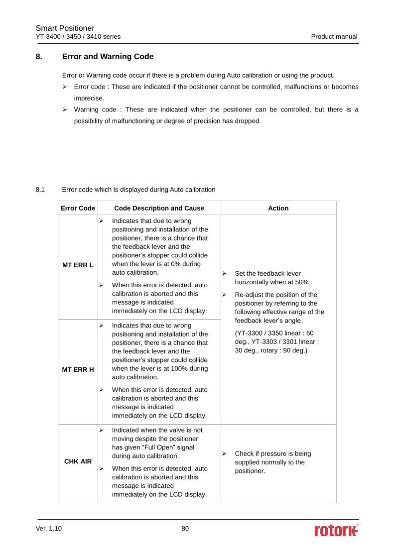
Smart Positioner YT-3400 / 3450 / 3410 series Product manual
Ver. 1.10 80
8. Error and Warning Code
Error or Warning code occur if there is a problem during Auto calibration or using the product.
Error code : These are indicated if the positioner cannot be controlled, malfunctions or becomes
imprecise.
Warning code : These are indicated when the positioner can be controlled, but there is a
possibility of malfunctioning or degree of precision has dropped.
8.1 Error code which is displayed during Auto calibration
Error Code Code Description and Cause Action
MT ERR L
Indicates that due to wrong
positioning and installation of the
positioner, there is a chance that
the feedback lever and the
positioner’s stopper could collide
when the lever is at 0% during
auto calibration.
When this error is detected, auto
calibration is aborted and this
message is indicated
immediately on the LCD display.
Set the feedback lever
horizontally when at 50%.
Re-adjust the position of the
positioner by referring to the
following effective range of the
feedback lever’s angle
(YT-3300 / 3350 linear : 60
deg., YT-3303 / 3301 linear :
30 deg., rotary : 90 deg.)
MT ERR H
Indicates that due to wrong
positioning and installation of the
positioner, there is a chance that
the feedback lever and the
positioner’s stopper could collide
when the lever is at 100% during
auto calibration.
When this error is detected, auto
calibration is aborted and this
message is indicated
immediately on the LCD display.
CHK AIR
Indicated when the valve is not
moving despite the positioner
has given “Full Open” signal
during auto calibration.
When this error is detected, auto
calibration is aborted and this
message is indicated
immediately on the LCD display.
Check if pressure is being
supplied normally to the
positioner.
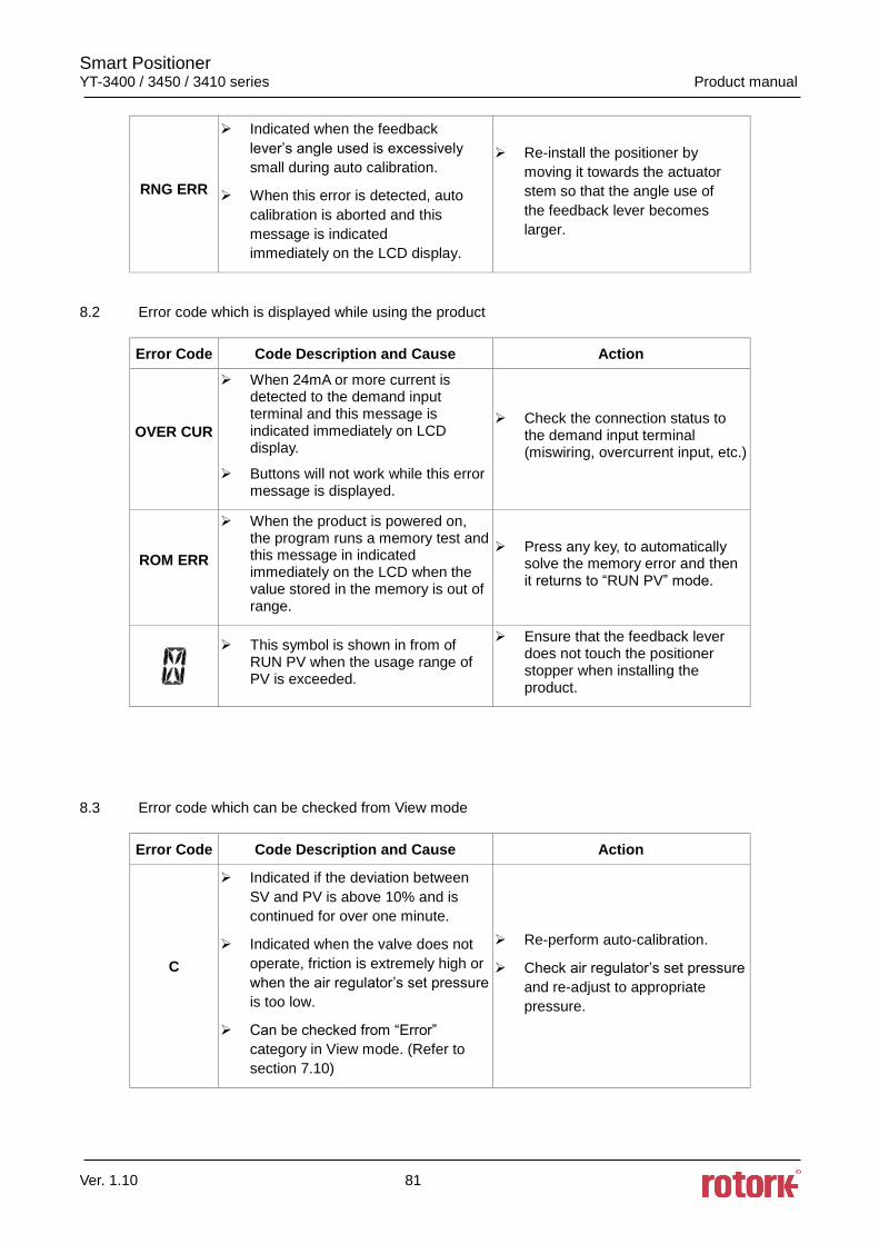
Smart Positioner YT-3400 / 3450 / 3410 series Product manual
Ver. 1.10 81
RNG ERR
Indicated when the feedback
lever’s angle used is excessively
small during auto calibration.
When this error is detected, auto
calibration is aborted and this
message is indicated
immediately on the LCD display.
Re-install the positioner by
moving it towards the actuator
stem so that the angle use of
the feedback lever becomes
larger.
8.2 Error code which is displayed while using the product
Error Code Code Description and Cause Action
OVER CUR
When 24mA or more current is detected to the demand input terminal and this message is indicated immediately on LCD display.
Buttons will not work while this error message is displayed.
Check the connection status to the demand input terminal (miswiring, overcurrent input, etc.)
ROM ERR
When the product is powered on, the program runs a memory test and this message in indicated immediately on the LCD when the value stored in the memory is out of range.
Press any key, to automatically solve the memory error and then it returns to “RUN PV” mode.
This symbol is shown in from of RUN PV when the usage range of PV is exceeded.
Ensure that the feedback lever does not touch the positioner stopper when installing the product.
8.3 Error code which can be checked from View mode
Error Code Code Description and Cause Action
C
Indicated if the deviation between
SV and PV is above 10% and is
continued for over one minute.
Indicated when the valve does not
operate, friction is extremely high or
when the air regulator’s set pressure
is too low.
Can be checked from “Error”
category in View mode. (Refer to
section 7.10)
Re-perform auto-calibration.
Check air regulator’s set pressure
and re-adjust to appropriate
pressure.
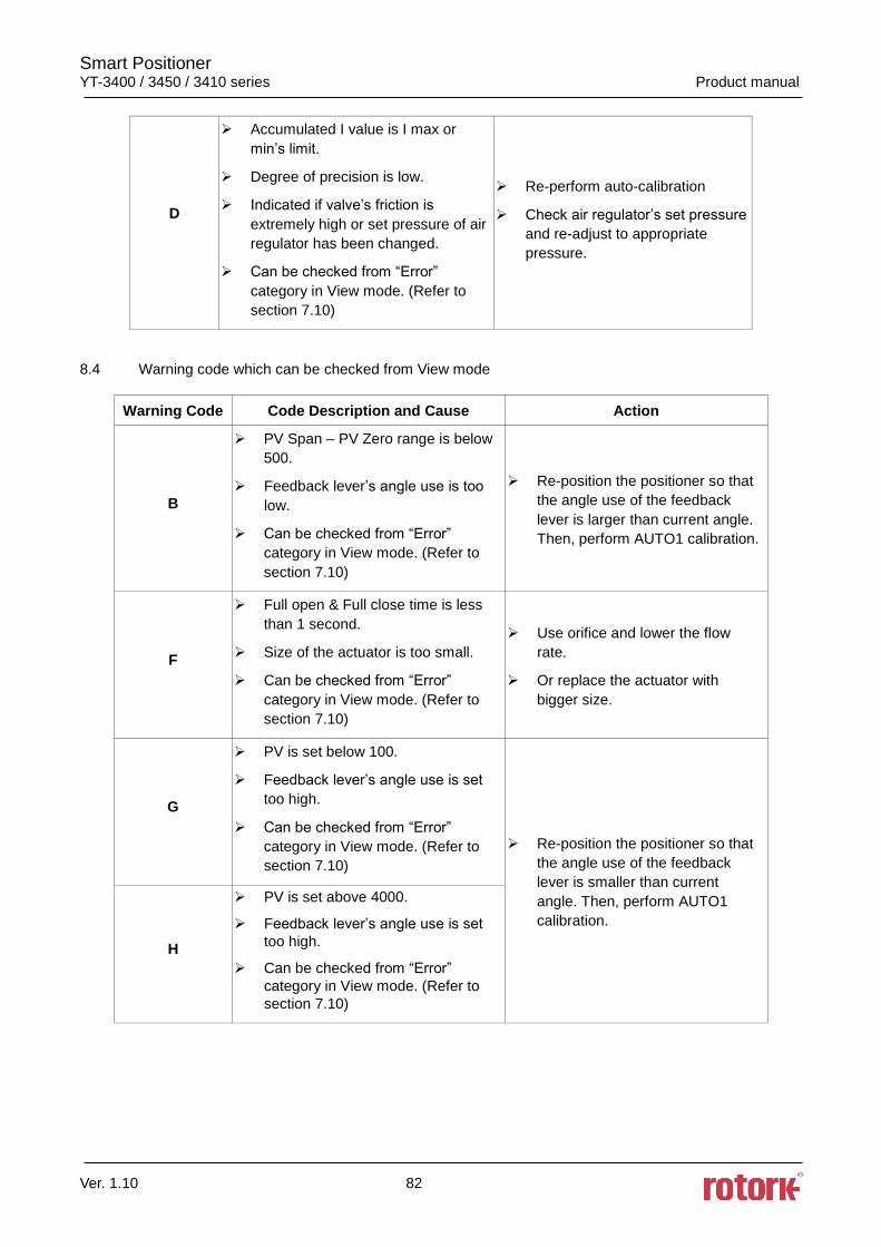
Smart Positioner YT-3400 / 3450 / 3410 series Product manual
Ver. 1.10 82
D
Accumulated I value is I max or
min’s limit.
Degree of precision is low.
Indicated if valve’s friction is
extremely high or set pressure of air
regulator has been changed.
Can be checked from “Error”
category in View mode. (Refer to
section 7.10)
Re-perform auto-calibration
Check air regulator’s set pressure
and re-adjust to appropriate
pressure.
8.4 Warning code which can be checked from View mode
Warning Code Code Description and Cause Action
B
PV Span – PV Zero range is below
500.
Feedback lever’s angle use is too
low.
Can be checked from “Error”
category in View mode. (Refer to
section 7.10)
Re-position the positioner so that
the angle use of the feedback
lever is larger than current angle.
Then, perform AUTO1 calibration.
F
Full open & Full close time is less
than 1 second.
Size of the actuator is too small.
Can be checked from “Error”
category in View mode. (Refer to
section 7.10)
Use orifice and lower the flow
rate.
Or replace the actuator with
bigger size.
G
PV is set below 100.
Feedback lever’s angle use is set
too high.
Can be checked from “Error”
category in View mode. (Refer to
section 7.10)
Re-position the positioner so that
the angle use of the feedback
lever is smaller than current
angle. Then, perform AUTO1
calibration.
H
PV is set above 4000.
Feedback lever’s angle use is set
too high.
Can be checked from “Error”
category in View mode. (Refer to
section 7.10)
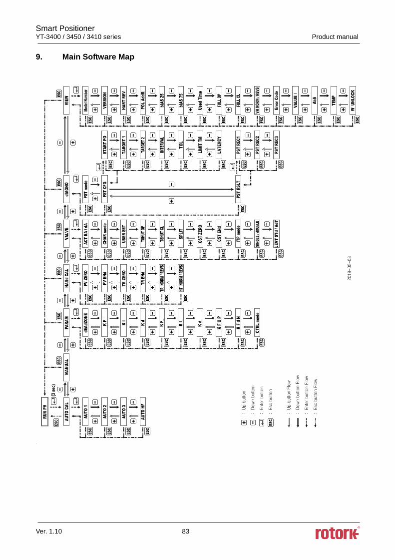
Smart Positioner YT-3400 / 3450 / 3410 series Product manual
Ver. 1.10 83
9. Main Software Map
Smart Positioner YT-3400 / 3450 / 3410 series Product manual
Ver. 1.10 84
Manufacturer: Rotork YTC Limited
Address: 81, Hwanggeum-ro, 89 Beon-gil, Yangchon-eup, Gimpo-si, Gyeonggi-do, South Korea
Postal code: 10048
Tel: +82-31-986-8545
Fax: +82-70-4170-4927
Email: [email protected]
Homepage : http://www.ytc.co.kr
Issued : 2020-01-02
Copyright © Rotork YTC Limited. All Rights Reserved.