Embed Size (px)
Citation preview
Imaging Beyond VisibleTM SUI Digital Line Scan Camera
4110-0250 Rev. E Page 1 of 100 © 2020 Collins Aerospace Systems Date Printed: 13-Apr-2020
This document does not contain any export controlled technical data
Operation Manual: LDH2: 92 kHz InGaAs Linescan Camera for OCT
LDM: 46 kHz InGaAs Linescan Camera for MV
330 Carter Road, Suite 100, Princeton, NJ 08540 Tel: 1-609-333-8200
Go to: http://www.sensorsinc.com
Imaging Beyond VisibleTM SUI Digital Line Scan Camera
4110-0250 Rev. E Page 2 of 100 © 2020 Collins Aerospace Date Printed: 13-Apr-2020
This document does not contain any export controlled technical data
Collins Aerospace Proprietary Subject to the restriction on the title or cover page.
NOTICES ©2010-20 Sensors Unlimited, Inc., a wholly owned subsidiary of Collins Aerospace, all rights reserved. This document may not be reproduced nor transmitted in any form or by any means, either electronic or mechanical, without the express written permission of Collins Aerospace. Every effort is made to ensure the information in this manual is accurate and reliable. Use of the products described herein is understood to be at the user’s risk. Collins Aerospace assumes no liability whatsoever for the use of the products detailed in this document and reserves the right to make changes in specifications at any time and without notice. The modifiers and phrases SUITM, Sensors knows IRTM, Imaging Beyond the VisibleTM, Visible-InGaAsTM, NIR PerfectTM, NI®, IMAQTM, LabVIEW® and Camera Link® are used in this manual. “SUI”, “Sensors knows IR”, and “NIR Perfect” are all trademarks of Sensors Unlimited, Inc. “NI, IMAQ and LabVIEW are trademarks of National Instruments. Camera Link is a registered trademark of the Automated Imaging Association. All other trademarks or intellectual property mentioned herein belong to their respective owners.
CE Compliance The SUI LDH2 and LDM Near Infrared cameras conform to the requirements of FCC PART 15, SUBPART B, CLASS A, 2006 for conducted emissions and radiated emissions. They also meet class A level CE standards for emission, immunity & ESD. Compliance requires the Camera Link SDR cable connector to be fully seated on the camera mating connector with the jack screws completely tightened and when the provided power supply is used. This power supply conforms to CE and UL standards as a stand alone unit. Users providing their own power supply should follow the power supply connection method described in Section 3.1.1 to minimize emissions.
Imaging Beyond VisibleTM SUI Digital Line Scan Camera
4110-0250 Rev. E Page 3 of 100 © 2020 Collins Aerospace Date Printed: 13-Apr-2020
This document does not contain any export controlled technical data
Collins Aerospace Proprietary Subject to the restriction on the title or cover page.
Table of Contents (click on line to jump to section)
1 INTRODUCTION ................................................................................................................ 6
1.1 SYSTEM DESCRIPTION .................................................................................................. 6 1.2 SYSTEM CONTENTS ...................................................................................................... 7 1.3 SAFETY CONSIDERATIONS ............................................................................................ 9 1.4 OPTICAL CONSIDERATIONS ..........................................................................................10 1.5 CAMERA CLEANING .....................................................................................................10
2 GETTING STARTED .........................................................................................................12
2.1 HARDWARE INSTALLATION ...........................................................................................12 2.2 SOFTWARE INSTALLATION (OPTIONAL) ..........................................................................14
3 CAMERA HARDWARE INTERFACES ..............................................................................16
3.1 CAMERA ELECTRICAL INTERFACES ...............................................................................16 3.1.1 Power Input ...........................................................................................................16 3.1.2 Camera Link Data Interface ...................................................................................17 3.1.3 Synchronization Output ..........................................................................................21 3.1.4 Trigger Input ..........................................................................................................21 3.1.5 Status LED ............................................................................................................21
3.2 CAMERA MECHANICAL INTERFACES ..............................................................................22 3.2.1 Physical Characteristics .........................................................................................22 3.2.2 Mounting the Camera ............................................................................................25 3.2.3 Thermal Management ............................................................................................25
3.3 CAMERA OPTICAL INTERFACES ....................................................................................25 3.3.1 Lens Mounting Plate ..............................................................................................25 3.3.2 Available Lens Adapters ........................................................................................26 3.3.3 Installation of Lens and Adjustable Adapter ...........................................................28 3.3.4 Lens Stop-down Mode ...........................................................................................31 3.3.5 C-Mount Lens Adapter ...........................................................................................31
4 PRINCIPALS OF OPERATION .........................................................................................33
4.1 FOCAL PLANE ARRAY OPERATION ................................................................................33 4.2 CAMERA SYSTEM OPERATION ......................................................................................36
5 CAMERA FUNCTIONS AND CONTROL SOFTWARE INTERFACE .................................39
5.1 COMMUNICATION PROTOCOL .......................................................................................39 5.2 COMMAND FORMAT AND RESPONSE .............................................................................39 5.3 STARTUP MESSAGING .................................................................................................41 5.4 COMMAND SET............................................................................................................41
5.4.1 Configuration Commands ......................................................................................42 5.4.2 Serial Communication Interface Commands ..........................................................49 5.4.3 Correction Commands ...........................................................................................53 5.4.4 Pixel Clock Command............................................................................................58 5.4.5 Frame and Exposure Control Commands ..............................................................58 5.4.6 Trigger Commands ................................................................................................62 5.4.7 Gain and Sensitivity Commands ............................................................................69 5.4.8 Imager Scanning Commands .................................................................................74
Imaging Beyond VisibleTM SUI Digital Line Scan Camera
4110-0250 Rev. E Page 4 of 100 © 2020 Collins Aerospace Date Printed: 13-Apr-2020
This document does not contain any export controlled technical data
Collins Aerospace Proprietary Subject to the restriction on the title or cover page.
5.4.9 Thermal Commands ..............................................................................................75 5.4.10 Camera Information Commands ........................................................................77 5.4.11 Status and Reset Commands ............................................................................81 5.4.12 Test Commands.................................................................................................87
6 SPECIFICATIONS ............................................................................................................90
6.1 MECHANICAL SPECIFICATIONS .....................................................................................90 6.2 ENVIRONMENTAL AND POWER SPECIFICATIONS ............................................................90 6.3 ELECTRO-OPTIC PERFORMANCE SPECIFICATIONS (TYPICAL VALUES) .............................91
7 PRODUCT SUPPORT ......................................................................................................92
7.1 COMMON PROBLEMS AND SOLUTIONS ..........................................................................92 7.2 CUSTOMER SUPPORT ..................................................................................................94 7.3 WARRANTY .................................................................................................................95
8 LIST OF ABBREVIATIONS ...............................................................................................96
9 NOTES ..............................................................................................................................98
APPENDIX A: CAMERA COMMAND SUMMARY APPENDIX B: FACTORY DEFAULT GLOBAL AND OPERATIONAL PARAMETERS
Imaging Beyond VisibleTM SUI Digital Line Scan Camera
4110-0250 Rev. E Page 5 of 100 © 2020 Collins Aerospace Date Printed: 13-Apr-2020
This document does not contain any export controlled technical data
Collins Aerospace Proprietary Subject to the restriction on the title or cover page.
List of Figures
Figure 1. Camera back panel and power connector pin assignment. ........................... 16 Figure 2. Camera Link interface timing diagram ........................................................... 19 Figure 3. Mechanical drawing of LDH2/LDM cameras including optical path stack-up 24 Figure 4. LD to Nikon F-mount lens adapter – part #8000-0171. ................................. 26 Figure 5. LD to Canon FD-mount lens adapter - part #8000-0172 (out of production). 27 Figure 6. Drawing of adapter panel ring showing spanner holes. ................................. 29 Figure 7. Location of lens adapter focus and rotation adjustment set screws. ............. 30 Figure 8. Mechanical drawing of C mount lens adapter ............................................... 32 Figure 9. Typical QE for front-side illuminated SUI linear photodiode arrays. .............. 33 Figure 10. Simplified pixel schematic. .......................................................................... 34 Figure 11. Camera system signal flow diagram. .......................................................... 37 Figure 12. Camera memory layout. .............................................................................. 42 Figure 13. Trigger mode 0 exposure and readout timing sequence. ............................ 62 Figure 14. Trigger mode 1 exposure and readout timing sequence. ............................ 63 Figure 15. Trigger mode 2 exposure and readout timing sequence. ............................ 64 Figure 16. Trigger mode 3 exposure and readout timing sequence. ............................ 65
List of Tables
Table 1. Available camera accessory kits. ..................................................................... 8 Table 2. Digital output SDR 26-pin connector signal assignment. ................................ 18 Table 3. Maximum line frequency and exposure time by array type. ........................... 36 Table 4. Line format of camera command return strings. ............................................. 41 Table 5. User configurable global settings. .................................................................. 43 Table 6. User configurable operational settings. .......................................................... 44 Table 7. Error value descriptions, causes and resolutions. .......................................... 82
Imaging Beyond VisibleTM SUI Digital Line Scan Camera
4110-0250 Rev. E Page 6 of 100 © 2020 Collins Aerospace Date Printed: 13-Apr-2020
This document does not contain any export controlled technical data
Collins Aerospace Proprietary Subject to the restriction on the title or cover page.
1 INTRODUCTION
1.1 SYSTEM DESCRIPTION The Sensors Unlimited Inc. LDH2 and LDM Near Infrared Line Scan Cameras are a small, versatile imaging tools that supports SUI’s line of LC-series Indium Gallium Arsenide linear focal plane arrays. Designed for laboratory or field use, these cameras require only a nominal DC voltage for operation (12 V output AC adapter provided). The lack of cryogenic liquids or moving parts makes them suitable for both industrial applications and laboratory research. As a line scan device, images are constructed from dynamic (moving) scenes, such as imaging parts moving down a conveyor belt, or scenes scanned by a galvanomic tilted mirror. Another linescan method is for use in dispersed wavelength applications, as in a spectrograph, where displacement along the linescan axis represents units other than distance units. The 92 kHz LDH2 camera (the 2nd generation Linear Digital Highspeed camera) is specifically targeted for use with interferometric spectrographs used to recover scattering depth line profiles in Optical Coherence Tomography systems. These are being increasingly used in bio-medical or high precision industrial imaging. The high line readout speeds offered by this camera reach 100 Mega pixels per second and 91,911 lines per second, a rate achieved by transferring two 12-bit pixel values per Camera Link strobe clock cycle. As most machine vision applications do not need those speeds, an alternate version, the LDM (for Linear Digital Machine vision) is offered with its speed restricted to 50 Mpix/s and 45,956 lps in order to provide 14-bit intensity resolution. Both cameras offer slower line rates with longer exposure times to permit meeting the users’ needs for sensitivity or to synchronize to the pace of external systems. To avoid condensation, the focal plane array is mounted in a hermetically sealed package. The arrays used in this camera include a single-stage thermoelectric cooler and a thermistor for temperature sensing, which allows the array to be stabilized to a preset temperature. The camera’s optical sensitivity nominally covers the 0.8 - 1.7 µm wavelength range. These camera models are focused on supporting SUI latticed-matched InGaAs focal plane arrays (FPAs) with pixel formats of 1024 pixels on 25 µm pitch and pixel apertures of 25, or 500 µm. Other array formats or wavelength ranges are possible. Contact SUI for currently supported PDAs or to discuss development of solutions for other applications. The SUI LDH2/LDM cameras use 8 ADCs to readout the SUI LC readout integrated circuit (ROIC), multiplexing the ADC outputs into a single camera sequence of pixels for transmission over the digital interface. The ADC clock rate is 12.5 Mpix/s for these 1.7 micron wavelength cutoff arrays, with a pixel rate of 100 mega-pixels per second achieved by using the ADCs to simultaneously read 8 adjacent pixels of the array in parallel.
Imaging Beyond VisibleTM SUI Digital Line Scan Camera
4110-0250 Rev. E Page 7 of 100 © 2020 Collins Aerospace Date Printed: 13-Apr-2020
This document does not contain any export controlled technical data
Collins Aerospace Proprietary Subject to the restriction on the title or cover page.
The analog output signal of the FPA is digitized by the cameras with an internal resolution of 14 bits. The user can select to process the digitized data using a pixel-by-pixel two-point correction (offset and response gain) and bad pixel substitution. Offset correction compensates for fixed pattern non-uniformities along with the dark current signal, and gain correction compensates for the photoresponse non-uniformity. The digital data is transmitted in a Base Camera Link compatible format via the SDR 26-pin connector (also known as a mini-Camera Link connector) of the cameras. The LDM version of the camera transfers one pixel value with a bit depth of 14 bits per pixel on each Camera Link strobe clock to achieve a maximum line rate of 45,956 lps, The LDH2 sends two pixels of 12-bit data for each strobe, using all 24 of the available data lines in the interface. ASCII serial commands sent through the Camera Link asynchronous serial communication port, enable the user to control camera settings, for instance the user can continuously vary the integration time settings. The user can also use one of the camera’s preconfigured operating modes (OPRs) with or without pixel-by-pixel two-point non-uniformity corrections. These OPRs offer a set of factory set integration time and FPA sensitivity combinations to cover a wide range of light-intensity, line-rate and full-well needs. For the LDH2, the OPRs also select the most appropriate 12-bits of the available 14-bit data for the best signal to noise. The user can also edit these OPR settings or create their own range of preset modes for quick switching between standard setups. The SUI-LDH2 and LDM cameras are closely related to the SUI-LDH linescan camera series, sharing a similar command set, the LC-series of InGaAs photodiode arrays and some components. Both are related to the older SUI-LDV linescan cameras, which use previous generations of ROICs, but also have similar command sets.
1.2 SYSTEM CONTENTS An order for a SUI LDH2 or LDM camera includes the following:
SUI LDH2 or LDM camera body
SUI mini CD containing support documentation and software, including the configuration file for National Instruments Camera Link frame grabber cards
The OEM customer, who may be wiring the camera into a system, can order the camera without any accessory kit to minimize waste of unneeded parts. In this case, each camera is individually packaged in a small cardboard box for shipment. First-time and repeat customers, who need to be able to power up the camera from local AC power sources upon receipt, will need to order a LDH2/LDM accessory kit. Several different accessory kits are available for these cameras, which differ only by the lens adapter choice include in the kit. Note that these kits do not include a lens, as the diversity of line-scan applications need different working distance and magnification solutions.
Imaging Beyond VisibleTM SUI Digital Line Scan Camera
4110-0250 Rev. E Page 8 of 100 © 2020 Collins Aerospace Date Printed: 13-Apr-2020
This document does not contain any export controlled technical data
Collins Aerospace Proprietary Subject to the restriction on the title or cover page.
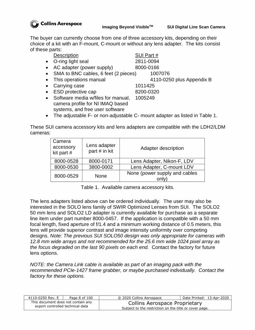
The buyer can currently choose from one of three accessory kits, depending on their choice of a kit with an F-mount, C-mount or without any lens adapter. The kits consist of these parts:
Description SUI Part #
O-ring light seal 2811-0094
AC adapter (power supply) 8000-0166
SMA to BNC cables, 6 feet (2 pieces) 1007076
This operations manual 4110-0250 plus Appendix B
Carrying case 1011425
ESD protective cap 8200-0320
Software media w/files for manual, 1005249 camera profile for NI IMAQ based systems, and free user software
The adjustable F- or non-adjustable C- mount adapter as listed in Table 1.
These SUI camera accessory kits and lens adapters are compatible with the LDH2/LDM cameras:
Camera accessory kit part #
Lens adapter part # in kit
Adapter description
8000-0528 8000-0171 Lens Adapter, Nikon-F, LDV
8000-0530 3800-0002 Lens Adapter, C-mount LDV
8000-0529 None None (power supply and cables
only)
Table 1. Available camera accessory kits.
The lens adapters listed above can be ordered individually. The user may also be interested in the SOLO lens family of SWIR Optimized Lenses from SUI. The SOLO2 50 mm lens and SOLO2 LD adapter is currently available for purchase as a separate line item under part number 8000-0457. If the application is compatible with a 50 mm focal length, fixed aperture of f/1.4 and a minimum working distance of 0.5 meters, this lens will provide superior contrast and image intensity uniformity over competing designs. Note: The previous SUI SOLO50 design was only appropriate for cameras with 12.8 mm wide arrays and not recommended for the 25.6 mm wide 1024 pixel array as the focus degraded on the last 90 pixels on each end. Contact the factory for future lens options. NOTE: the Camera Link cable is available as part of an imaging pack with the recommended PCIe-1427 frame grabber, or maybe purchased individually. Contact the factory for these options.
Imaging Beyond VisibleTM SUI Digital Line Scan Camera
4110-0250 Rev. E Page 9 of 100 © 2020 Collins Aerospace Date Printed: 13-Apr-2020
This document does not contain any export controlled technical data
Collins Aerospace Proprietary Subject to the restriction on the title or cover page.
1.3 SAFETY CONSIDERATIONS The camera can be powered using a 8-16 V DC power supply capable of providing a minimum of 8 W with the camera ambient temperature held within the specified case temperature operating range of -10 to + 50 C. The camera is protected by an overvoltage , reverse voltage and excessive current shutdown circuit, which will shut down the internal power supply until the camera is disconnected and then reconnected with the proper voltages. However, this circuit could be damaged by excessively high voltages. It is also important that the ambient environment is within the camera operating range before power is applied. NOTE: If the camera does not power up with the correct supply voltages or with the COLLINS AEROSPACE supplied AC convertor, there may be a fault drawing excessive current. Please contact the factory applications engineers for assistance. The linear focal plane array is mounted behind a protective window with a broadband antireflective coating. When changing lenses or mounting the camera in any optical arrangement, take care not to scratch or touch this window. To prevent fire, shock hazard or damage to the camera, do not expose to rain or excessive moisture. Do not disassemble camera. Do not remove screws or covers. There are no user serviceable parts inside. Removal of any panel will void the warranty. When handling the camera take precautions to avoid electro-static discharge (ESD) to any exposed electrical connector pins To minimize RF interference with sensitive equipment, ensure that the Camera Link connectors are fully seated and the connector jack screws fully tightened to the stop.
Imaging Beyond VisibleTM SUI Digital Line Scan Camera
4110-0250 Rev. E Page 10 of 100 © 2020 Collins Aerospace Date Printed: 13-Apr-2020
This document does not contain any export controlled technical data
Collins Aerospace Proprietary Subject to the restriction on the title or cover page.
1.4 OPTICAL CONSIDERATIONS The front panel of the camera is threaded for M42x1-6H with a nominal 5.7 mm distance to the focal plane (the same thread as a U-mount, but a closer focal distance). This was chosen because of its large open diameter and its closeness to the focal plane avoids limiting the optical aperture of the array. The design makes for convenient adaption to other formats, or for mounting on a spectrometer. The camera body is provided by itself or with one of several accessory kits which include may include one of a couple different lens adapters. Currently available to thread into the M42x1 U-mount thread, are a choice of accessory kits with a:
F-mount – a bayonet mount associated with the Nikon family of lenses lens adapters
C-mount – a 1 inch diameter thread mount associated with CCTV cameras See section 3.3 for more information on the optical-mechanical interfaces supported. Glass lenses are generally compatible with short wave infrared cameras. Note: The antireflective coatings and lens materials on most high quality photographic lenses are optimized for visible light and have larger reflectivity in the short wave infrared. Optimum image sharpness requires a lens designed specifically for focusing all of the short wave infrared wavelengths used in the application. The lens should also be designed to fully illuminate the length of the array installed in the SUI LDH2 or LDM cameras. A C-mount lens is generally designed to work with focal plane diagonal dimensions of 11 mm (2/3” format) or 16 mm (1” format). Only the latter type will fully illuminate a 12.8 mm long linear array, but it won’t properly illuminate a 25.6 mm long array. Therefore, only 35 mm photographic lenses with F mounts should be considered for use with the long arrays. SUI has a SWIR lens option available, a 50 mm f/1.4 lens designed for the SWIR wavelength range, which may ordered with a M42 adapter for use with the LD camera family. The new SOLO2 lens is a superior choice over visible photographic lenses for SUI InGaAs arrays. This lens has a minimum focus distance of 0.5 m, and can be ordered with the adapter as part number 8000-0457 LENS ASSY, LD SOLO2 50 STANDALONE LENS WITH ADAPTER AND CASE. NOTE: The previous SOLO 50 lens is only appropriate for smaller array lengths, as the focus falls off for the last 10% on either end of the 25.6 mm long linear arrays. The SOLO2 version maintains focus, but illumination intensity still falls modestly at the ends.
1.5 CAMERA CLEANING Please power down the camera before performing any camera cleaning operation.
Imaging Beyond VisibleTM SUI Digital Line Scan Camera
4110-0250 Rev. E Page 11 of 100 © 2020 Collins Aerospace Date Printed: 13-Apr-2020
This document does not contain any export controlled technical data
Collins Aerospace Proprietary Subject to the restriction on the title or cover page.
Use a soft cloth moistened with a small amount of water or isopropyl alcohol to clean the outside of the camera enclosure or the power supply housing. If the protective window of the focal plane array requires cleaning, follow these steps:
With the focal plane array mounted in the camera, use clean, dry compressed air to blow loose particles off the window. This step alone is often sufficient to clean the window. Do not use compressed air gas canisters for this operation, since they may contain fluid and can thermally shock the window.
Using lint free, lens cleaning paper moistened with isopropyl alcohol; carefully wipe the surface of the window by dragging the moistened paper from one edge of the window to the other in a single motion. The paper may need to be folded so that it does not contact any other surface than the glass and covers the window from edge to edge. Use the paper only once and wipe in one direction across the window surface. If the surface is still not clean, repeat this step always wiping in the same direction using a new piece of moistened cleaning paper until the window is clean.
Note: Imaging a point light source from a distance (without a lens), say using a LED or even a small pen lamp at 2 meters, will show dust on the window that might interfere with images when later used with small aperture optics like a microscope or closed down imaging lens. If moving the source sideways causes the spot to shift from pixel to pixel, the cause is on the window. If light cleaning attempts fail to move a dark spot from the original pixel location(s), the dark spot may be a window scratch or dig in the AR coating and further cleaning attempts should be avoided to prevent further damage.
Imaging Beyond VisibleTM SUI Digital Line Scan Camera
4110-0250 Rev. E Page 12 of 100 © 2020 Collins Aerospace Date Printed: 13-Apr-2020
This document does not contain any export controlled technical data
Collins Aerospace Proprietary Subject to the restriction on the title or cover page.
2 GETTING STARTED
2.1 HARDWARE INSTALLATION To connect your camera hardware, perform the following:
1. Mount the camera body, if applicable. See section 3.2.2 for additional information on provisions for camera mounting.
2. Mount the optics to be used to the camera, if applicable. If one of the provided standard lens mounts is to be used, see section 3.3 for additional information.
3. Install the frame grabber you will be using for data collection following the manufacturer’s instructions.
4. Note: The SUI LDH2 camera can be interfaced with most frame grabbers, but SUI has verified its operation with National Instruments PCIe-1427, PCIe-1429 and PCIe-1430 cards only. The LDM can be used with these cards and with the older PCI-1426/8 cards, whose need for 20 µs between image frames prevents achieving full rates with the LDH2 camera. For information on presently supported National Instruments frame grabber models, contact a factory applications engineer. For National Instruments frame grabbers, it is recommended that installation of the software drivers be installed before the frame grabber hardware. (See section 2.2 for additional information on software installation.) For the NI PCIe-1427 and 1429 frame grabber cards, and others which use LVAL low time for image memory managemen between sets of lines, it is recommended that the camera be operated with the overscan feature turned off, which is the camera’s factory default setting – see section 5.4.8.3 for further discussion. If the overscan feature is turned on for frame grabbers that need prevalid pixels, the acquisition window definition for the frame grabber configuration (e.g., the .ICD file for NI environments) must also be adjusted, to ignore the first 56 inactive pixels.
5. Connect the Camera Link cable to the frame grabber and the camera, inserting the connector so it is fully seated and the shell is parallel to the mating panel surface. Tighten the cable retention screws on both ends of the cable until reaching the stop. This is important for maintaining low RFI emissions.
6. If the supplied AC adapter is not being used, test the camera power source for proper voltage, polarity, and pin connections as indicated in section 3.1.1 before connecting the power cable to the camera. Ensure that the voltage is within the specified range – though the camera has overvoltage and reverse polarity protection, it is not immune to damage from excessive voltages. With the power source off, insert the power connector into the camera and tighten the screw lock. Apply power to the camera and wait for
Imaging Beyond VisibleTM SUI Digital Line Scan Camera
4110-0250 Rev. E Page 13 of 100 © 2020 Collins Aerospace Date Printed: 13-Apr-2020
This document does not contain any export controlled technical data
Collins Aerospace Proprietary Subject to the restriction on the title or cover page.
the status LED to turn solid green. See section 3.1.5 for information on the status LED operation.
7. Upon application of power, the Camera Link data lines and the asynchronous serial communications lines in the Camera Link interface will become active. The SUI-LDH2/LDM cameras will echo a multi-line firmware message on the serial SerTFG line pair, and then operation will begin according to user-configurable default parameters stored in non-volatile memory.
8. If either the sync output or trigger input of the camera are to be used, connect the SMA cables at the camera as appropriate. Tighten the cable SMA connector outer shell until fully seated to the camera’s mating connector, and rotate the BNC bayonet until it is fully seated to the system at the other end of the cable. If the sync output is to be used, connect the output to a load compliant with the requirements described in section 3.1.3. If the trigger input is used, connect it to a signal source compliant with the specifications of section 3.1.4. Take care not to confuse the sync output with the trigger input connections to obtain proper operation (damage will not be caused on appropriately sourced or sunk signals).
Imaging Beyond VisibleTM SUI Digital Line Scan Camera
4110-0250 Rev. E Page 14 of 100 © 2020 Collins Aerospace Date Printed: 13-Apr-2020
This document does not contain any export controlled technical data
Collins Aerospace Proprietary Subject to the restriction on the title or cover page.
2.2 SOFTWARE INSTALLATION (OPTIONAL) The LDH2 and LDM cameras are compatibile with the Camera Link interface specification 1.0, in the “Base” configuration. As such, operating software is generally specific to the Camera Link ‘frame grabber’ card selected for use and cannot be provided by Sensors Unlimited Inc. The output signal from the Camera Link interface is generic and relies on proper configuration of the receiving Camera Link device to obtain meaningful data. SUI has developed an Image Analysis application that works ONLY with National Instruments cards AND the NI-IMAQ suite; this is recommended hardware and software for those not experienced in Camera Link Machine Vision operation. To install software to control and collect data from the camera, perform the following:
1. Install driver software required by the frame grabber being used following the manufacturer’s instructions. Be sure to verify that the host computer meets the minimum system requirements specified by the frame grabber manufacturer. National Instruments IMAQ drivers must be installed before installing the board if a National Instruments frame grabber is used. NI-IMAQ Vision is National Instruments’ library of powerful functions for image processing that is distributed with their imaging frame grabber cards. This software library easily integrates with National Instruments LabVIEW Software, an extensive instrument-programming environment. Note: The SUI LDH2/LDM hardware will work with other Camera Link compatible frame grabber cards, but SUI provides basic troubleshooting support for NI cards only. NI-IMAQ versions 3.8, 4.1, 4.3 and 4.4 are compatible with SUI cameras and software; contact the factory before installing other versions when planning to use the SUI software.
2. Configure the frame grabber to accept the Camera Link interface signal timing documented in section 3.1.2. If using a National Instruments PCI-1427, PCI-1428 or PCIe-1429 frame grabber, a camera configuration file (extension .ICD) is provided on the SUITM mini CD shipped with the camera. This configuration file properly configures the frame grabber for the SUI LDH2’s Camera Link interface timing and allows the selection of camera operational modes for the factory configuration. Copy the configuration file from the mini CD to the IMAQ data directory for the IMAQ driver to access them (typical directory location is “C:\Program Files\National Instruments\NI_IMAQ\Data” for IMAQ revisions before 4.1 and “C:\Documents and Settings\All Users\Shared Documents\National Instruments\NI-IMAQ)” after that. Note: For the PCIe-1427, PCIe-1429 and the related PCIe-1430 frame grabber cards, it is recommended to operate the LDH2/LDM camera with its overscan feature turned off to avoid missing camera lines between frames. This is the default configuration for these models. The suppled NI ICD file on the mini-CD supports this mode with the first number of parameter setting “AcquisitionWindow ” to read “(0, 0, 1024, XXX. (The XXX refers to the user’s
Imaging Beyond VisibleTM SUI Digital Line Scan Camera
4110-0250 Rev. E Page 15 of 100 © 2020 Collins Aerospace Date Printed: 13-Apr-2020
This document does not contain any export controlled technical data
Collins Aerospace Proprietary Subject to the restriction on the title or cover page.
selected virtual image height.) See Section 5.4.8.3 in this manual for the command to turn the camera overscan on, and Sections 5.4.1 and 5.4.1.3 to save the changed configuration, if using a frame grabber that requires a set of pre-valid pixels to be transmitted with LVAL high before the active pixels. For the LDH2, the pre-valid pixels with overscan will be 56, for the LDM, 28.
3. Test camera data collection. Typically, software tools provided with the frame grabber can perform simple data collection operations to enable the chosen frame grabber configuration to be tested. If a National Instruments frame grabber is being used, the NI Measurement and Automation Explorer (MAX) should be used to configure and validate the hardware installation. See National Instruments documentation for operation of the Measurement and Automation Explorer. If more information on interfacing with the NI-IMAQ library is required, call a NI representative or SUI. It is recommended that data collection be successfully exercised using frame grabber-supplied tools before attempting to collect data with any third-party software applications.
4. Install any application software to be used following the manufacturer’s instructions. With NI frame grabbers, the SUI Image Analysis (SUI-IA) software application that can be used for data collection and analysis with the SUI LDH2/LDM camera is distributed on the SUI mini CD and can be installed after MAX has been run once. To install, navigate to the CD’s directory “../SUI Image Analysis Software” and run the installer executable. SUI-IA allows the user to control the camera settings, acquire the line scan data into a pseudo image, store these images or sequences of images (as movies), measure relative intensities of pixels, regions or spots, contrast enhance the image with tools like Histogram Equalization, take and store line profiles or histogram data, and apply false color intensity maps to the images.
Imaging Beyond VisibleTM SUI Digital Line Scan Camera
4110-0250 Rev. E Page 16 of 100 © 2020 Collins Aerospace Date Printed: 13-Apr-2020
This document does not contain any export controlled technical data
Collins Aerospace Proprietary Subject to the restriction on the title or cover page.
3 CAMERA HARDWARE INTERFACES
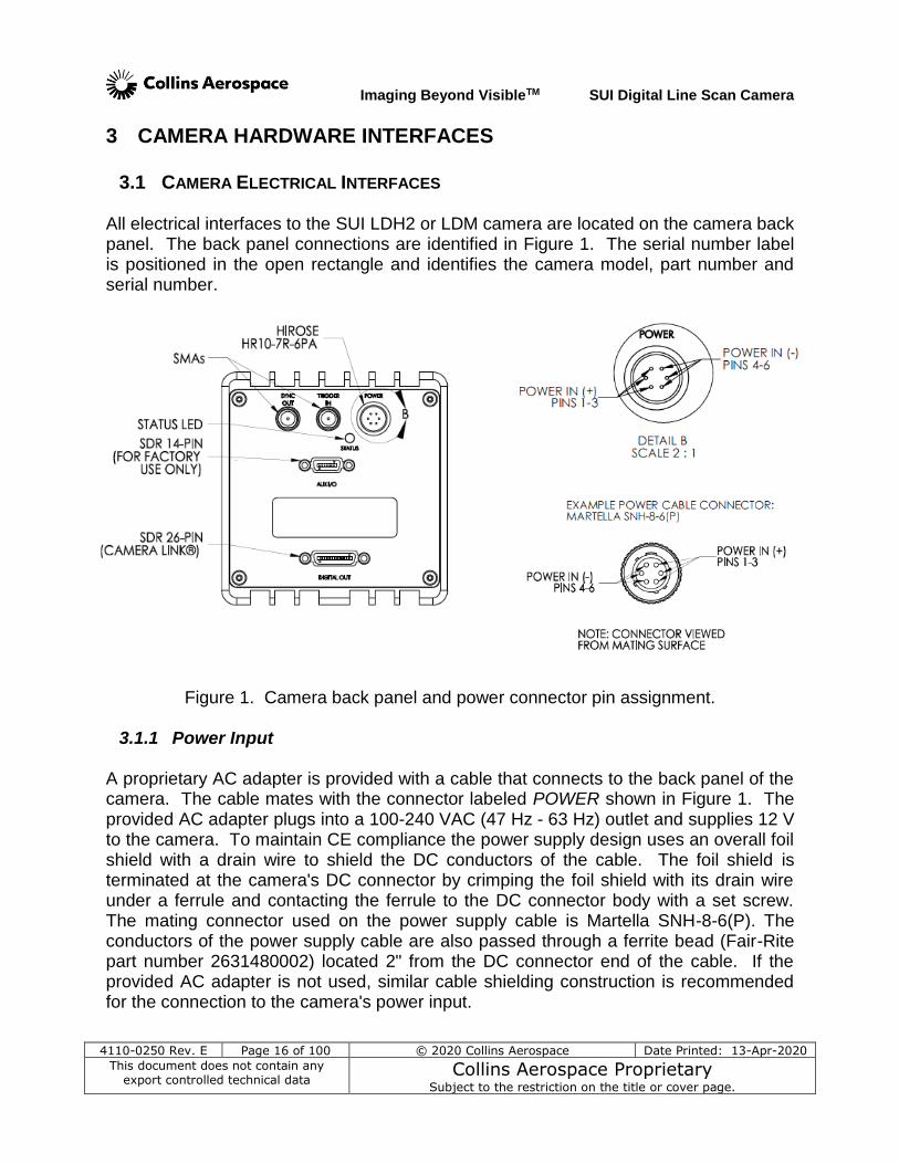
3.1 CAMERA ELECTRICAL INTERFACES All electrical interfaces to the SUI LDH2 or LDM camera are located on the camera back panel. The back panel connections are identified in Figure 1. The serial number label is positioned in the open rectangle and identifies the camera model, part number and serial number.
Figure 1. Camera back panel and power connector pin assignment.
3.1.1 Power Input
A proprietary AC adapter is provided with a cable that connects to the back panel of the camera. The cable mates with the connector labeled POWER shown in Figure 1. The provided AC adapter plugs into a 100-240 VAC (47 Hz - 63 Hz) outlet and supplies 12 V to the camera. To maintain CE compliance the power supply design uses an overall foil shield with a drain wire to shield the DC conductors of the cable. The foil shield is terminated at the camera's DC connector by crimping the foil shield with its drain wire under a ferrule and contacting the ferrule to the DC connector body with a set screw. The mating connector used on the power supply cable is Martella SNH-8-6(P). The conductors of the power supply cable are also passed through a ferrite bead (Fair-Rite part number 2631480002) located 2" from the DC connector end of the cable. If the provided AC adapter is not used, similar cable shielding construction is recommended for the connection to the camera's power input.
Imaging Beyond VisibleTM SUI Digital Line Scan Camera
4110-0250 Rev. E Page 17 of 100 © 2020 Collins Aerospace Date Printed: 13-Apr-2020
This document does not contain any export controlled technical data
Collins Aerospace Proprietary Subject to the restriction on the title or cover page.
If the provided AC adapter is not used, DC power between +8 V and +16 V must be applied with the proper polarity to the power connector. It is critical that the power connections be made to the proper connector pins, as shown in Figure 1. Do not exceed the maximum input voltage or damage might occur. The power source used must be able to supply a minimum of 9 W of continuous power to the camera. A power source with a maximum peak-to-peak ripple of 1 % of the DC supply voltage at full load is recommended to ensure camera performance.
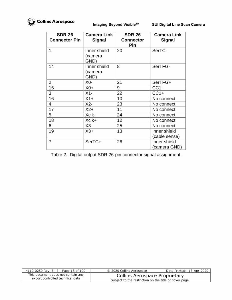
3.1.2 Camera Link Data Interface The digital data interface to the camera is through a base Camera Link compatible interface using low-voltage differential signaling (LVDS). Figure 2 shows the readout timing over this interface. This camera can be interfaced to most frame grabbers, but operation has been verified with National Instruments cards only. Optional imaging packs are available from SUI, Collins Aerospace that includes a NI PCIe-1427, or a PCI-1428 frame grabber card and a Camera Link cable. The PCIe-1427 frame grabber is recommended for the LDH2 and LDM for applications where it is important not to miss lines between frames (see note in Section 2.2 on software installation.) The SUI cameras communicate via the serial lines provided by the Camera Link
interface. This asynchronous serial communication is performed using 8 data bits, 1 stop bit, no parity, no flow control, and a configurable BAUD rate. (See the list of typical settings at the end of this section and see Appendix B for the default serial communication BAUD rate for your particular camera.) The signal assignment for the digital interface SDR 26-pin connector is shown in Table 2. This assignment corresponds to the Factory Configuration of the Camera Link standard.
Imaging Beyond VisibleTM SUI Digital Line Scan Camera
4110-0250 Rev. E Page 18 of 100 © 2020 Collins Aerospace Date Printed: 13-Apr-2020
This document does not contain any export controlled technical data
Collins Aerospace Proprietary Subject to the restriction on the title or cover page.
SDR-26 Connector Pin
Camera Link Signal
SDR-26 Connector
Pin
Camera Link Signal
1 Inner shield (camera GND)
20 SerTC-
14 Inner shield (camera GND)
8 SerTFG-
2 X0- 21 SerTFG+
15 X0+ 9 CC1-
3 X1- 22 CC1+
16 X1+ 10 No connect
4 X2- 23 No connect
17 X2+ 11 No connect
5 Xclk- 24 No connect
18 Xclk+ 12 No connect
6 X3- 25 No connect
19 X3+ 13 Inner shield (cable sense)
7 SerTC+ 26 Inner shield (camera GND)
Table 2. Digital output SDR 26-pin connector signal assignment.
Imaging Beyond VisibleTM SUI Digital Line Scan Camera
4110-0250 Rev. E Page 19 of 100 © 2020 Collins Aerospace Date Printed: 13-Apr-2020
This document does not contain any export controlled technical data
Collins Aerospace Proprietary Subject to the restriction on the title or cover page.
Pix
el a
nd
Lin
e t
imin
g
DV
AL
with
Ove
rsca
n
Da
taF
req
ue
ncy =
P x
N,
Du
ty C
ycle
= (
P x
N)
/ 5
0 M
Hz
No
te: If D
uty
Cycle
= 1
, D
VA
L
he
ld c
on
tin
uo
usly
hig
h.
7 x
N in
active
pix
els
No
te: F
igu
res n
ot to
sca
le
LV
AL
with
ou
t O
ve
rsca
n
Da
ta
N =
nu
mb
er
of fo
ca
l p
lan
e a
rra
y o
utp
ut p
ort
sM
= n
um
be
r o
f p
ixe
ls
P =
pix
el ra
te p
er
ou
tpu
t p
ort
LV
AL
with
Ove
rsca
n
Da
taF
req
ue
ncy =
FP
A R
ea
do
ut R
ate
LV
AL
hig
h w
idth
: (
( M
/ N
) +
7 )
/ P
M a
ctive
pix
els
Min
imu
m L
VA
L lo
w w
idth
:
4 S
TR
B c
ycle
s =
80
ns m
in
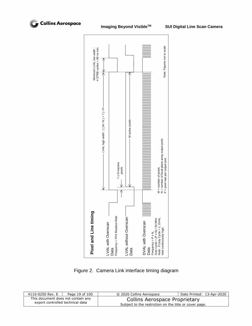
Figure 2. Camera Link interface timing diagram
Imaging Beyond VisibleTM SUI Digital Line Scan Camera
4110-0250 Rev. E Page 20 of 100 © 2020 Collins Aerospace Date Printed: 13-Apr-2020
This document does not contain any export controlled technical data
Collins Aerospace Proprietary Subject to the restriction on the title or cover page.
For the LDH2, the 12-bit image data PIX[11…0] (MSB corresponding to bit 11) is presented on the Camera Link output with PIX[7..0] connected to port A[7..0] and PIX[11..8] to port B[3..0] for the first pixel, and the second pixel transferred on the same clock edge and presented with PIX[7..0] connected to port C[7..0] and then PIX[11..8] connected to port B[7..4]. The STRB frequency is 50 MHz for a pixel transfer rate of 100 Mpixels per second. This camera is restricted to 12-bits even at lower line rates as frame grabber configurations do not have the flexibility to shift bit depth as line rate changes. However, the user may select which 12-bits of the 14-bits acquired are passed through the interface, depending on whether one needs to work with the largest full well or the smallest signals. For the predefined operating modes (OPRs – see Appendix B), the factory has selected the 12-bits that offer the best dynamic range for the integrator gain setting in use. The machine vision application rarely needs line speeds beyond 46 kHz, so the full 14-bit image data is made available in the LDM model. For this camera the output date signals PIX[13..0] (MSB corresponding to bit 13) are presented on the Camera Link output with lines PIX[7..0] connected to port A[7..0] and PIX[13..8] to port B[5..0]. The STRB frequency is also 50 MHz, and the resulting pixel transfer rate is 50 Mpixels per second. The average DVAL frequency during a valid line corresponds to the focal plane array pixel rate multiplied by the number of output ports of the supported focal plane array, unless this value is equal to the STRB frequency. If this value is equal to the STRB frequency, then DVAL is held continuously high. This is the case the LDH, LDH2 and LDM cameras. A timing diagram for the Camera Link interface is shown in Figure 2. The signals STRB, DVAL, LVAL, and and FVAL correspond to the signal names of the Camera Link standard issued by the Automated Imaging Association. FVAL is asserted (high) beginning with the first scan of the FPA by the camera and remains asserted until either scanning is disabled or the firmware is reset through the command interface. For a discussion of FPA line rates, see section 4.1. The time between valid lines is dependant on the selected frame time. To directly monitor when the camera is exposing, see section 3.1.3 for a description of the Synchronization Output signal. Asynchronous serial communication to the camera and a trigger input source are also supported on the Camera Link compatible interface on the SERTC±, SERTFG± and CC1± signals. See section 5 for a description of the asynchronous serial communication protocol and command set used by the camera. See section 5.4.6 for a description of supported camera trigger modes and section 3.4.1 for electrical specifications.
Imaging Beyond VisibleTM SUI Digital Line Scan Camera
4110-0250 Rev. E Page 21 of 100 © 2020 Collins Aerospace Date Printed: 13-Apr-2020
This document does not contain any export controlled technical data
Collins Aerospace Proprietary Subject to the restriction on the title or cover page.
Typical Camera Link Settings for interpreting Figure 2, the Camera Link interface timing diagram for the SU1024LDH2-1.7RT-0025/LC and -0500/LC cameras:
Active Horizontal Pixels: 1024 Active Vertical Pixels: 1 Pre-active Pixels: 0 [for camera setting SCAN:OVER OFF] Post-active Pixels: 0 Number of FPA Ports: 8 Camera Link Strobe Clock: 50 MHz Bit Depth: 12 bits * Serial Port Configuration:
BAUD 57600 Data Bits: 8 Parity: None Stop Bits: 1 Flow Control: None * For the SU1024LDM-1.7RT-0025/LC and -0500/LC cameras the Bit Depth listed above will be 14 bits.
3.1.3 Synchronization Output A synchronization timing signal output is available at the upper left SMA connector labeled SYNC OUT on the back of the camera as shown in Figure 1. This output timing signal follows the integration time of the camera, asserted high while the camera is integrating. The period of the SYNC OUT signal indicates the line rate of the focal plane array readout. This output signal is driven by a digital line driver powered from +3.3 V with an absolute maximum output current source/sink capability of ±24 mA. The
signal is driven through a 49 series termination resistor in the camera.
3.1.4 Trigger Input A trigger signal input connection is available at the SMA connector labeled TRIGGER IN on the back of the camera as shown in Figure 1. This input can be used for control of the line rate and exposure time. This trigger input accepts signals from 0 V to 5 V maximum. The thresholds for the Schmitt trigger input are < 1 V for logic low and >
1.9 V for logic high. The trigger input presents a 5.0 K load to ground to the signal driving source.
3.1.5 Status LED The status LED will illuminate whenever power is applied to the camera, either solid red, solid green, or it will alternate between red and green at a very steady 1 Hz rate to indicate a triggering error or an internal error. This rate will continue until the error is corrected.
Imaging Beyond VisibleTM SUI Digital Line Scan Camera
4110-0250 Rev. E Page 22 of 100 © 2020 Collins Aerospace Date Printed: 13-Apr-2020
This document does not contain any export controlled technical data
Collins Aerospace Proprietary Subject to the restriction on the title or cover page.
If the status LED is steadily illuminated red or green, it indicates the status of the temperature control of the focal plane array. When the status LED is illuminated red, the camera has not yet locked the focal plane array to its temperature set point (see Appendix B for focal plane array temperature set point). The temperature is considered locked when the imager is regulated to within ±0.1°C of the set point. The time required for the array temperature to reach lock from initial power on will range from 1 to 5 minutes depending on the ambient temperature conditions of the camera. The greater the difference between the ambient temperature and the set point temperature, the greater the time required to achieve temperature lock. The camera status LED will illuminate green when temperature lock is achieved. Note: After achieving lock, the temperature of the camera electronics may still take 10 to 15 additional minutes to completely stabilize. Therefore, when using the camera corrections, the user may notice the background noise level clipped at zero, with noise excursions that may cause artifacts in FFT processing of line data, or the mean level elevated above zero, until the array matches the temperature obtained when camera corrections were generated.. If the temperature cannot be held, the camera head status LED will turn red or may flicker randomly between red and green. Loss of temperature lock can occur for several reasons. The most common reason is that the camera is being operated at a body temperature greater than specified maximum. Another possibility is that the camera is operated in an enclosed environment that limits the ability of the case to radiate heat. See section 3.2.3 for more information on camera thermal management and section 5.4.9.2 for the HS:TEMP command to determine the camera body temperture. WARNING: If the status LED continues to indicate lack of temperature lock after these conditions have been remedied, disconnect power and contact the factory. Note: The status LED will flash between red and green on a one second interval if a camera error is encountered. (See section 5.4.11 for further details.) If the LED randomly changes color on a different time scale, it is an indication of temperature lock issues.
3.2 CAMERA MECHANICAL INTERFACES
3.2.1 Physical Characteristics
3.2.1.1 Cameras with array response to 1.7 µm using the T1 array package
Dimensions (Length x Width x Height)
6.1 cm x 7.37 cm x 7.62 cm 2.4 in x 2.9 in x 3.00 in Length includes I/O connectors, excludes lens adapter
Weight < 450 g and < 1 lbs (no lens)
Lens Mount M42X1-6H thread
Sensor Alignment 5.7 +/- 0.8 mm behind optical mount flange

Imaging Beyond VisibleTM SUI Digital Line Scan Camera
4110-0250 Rev. E Page 23 of 100 © 2020 Collins Aerospace Date Printed: 13-Apr-2020
This document does not contain any export controlled technical data
Collins Aerospace Proprietary Subject to the restriction on the title or cover page.
Optical Focal Distance 5.6 mm +/- 0.8 mm
Array Window 0.508 mm or 0.020 inch of BK7 glass with broadband AR coatings on both sides
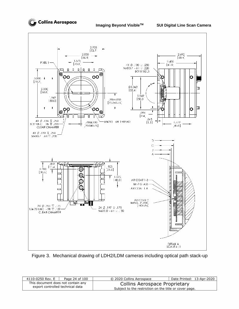
Mechanical drawings of the camera body including optical path stack-up dimensions is shown in Figure 3 for these two versions.
Imaging Beyond VisibleTM SUI Digital Line Scan Camera
4110-0250 Rev. E Page 24 of 100 © 2020 Collins Aerospace Date Printed: 13-Apr-2020
This document does not contain any export controlled technical data
Collins Aerospace Proprietary Subject to the restriction on the title or cover page.
Figure 3. Mechanical drawing of LDH2/LDM cameras including optical path stack-up
Imaging Beyond VisibleTM SUI Digital Line Scan Camera
4110-0250 Rev. E Page 25 of 100 © 2020 Collins Aerospace Date Printed: 13-Apr-2020
This document does not contain any export controlled technical data
Collins Aerospace Proprietary Subject to the restriction on the title or cover page.
Note: There are two different mounting holes sizes on the underside of the camera. This is intentional, and the user should be certain to attach the proper hardware to the correct hole.
3.2.2 Mounting the Camera
Type Description Hole Pattern
Tripod mount (bottom) 3 tapped ¼-20 holes spaced by 0.75 inch 2 tapped M6-6H holes spaced by 19.05 mm
In-line
Spectrometer mount (front)
M42 x 1 mm tapped hole – through plate Circle
4 x 8-32 tapped holes, ¼ inch depth 2 inch square
4 x M4-0.7 tapped holes, 6.3 mm depth 50 mm x 40 mm height x width
Side mount (left and right sides)
4 x M4x0.7-6H tapped holes, each side 50 mm x 45 mm height x width
3.2.3 Thermal Management
If the focal plane array is unable to reach or hold its temperature set point, additional thermal management of the camera may be necessary. (See section 3.1.5 and section 5.4.9 for methods of determining the focal plane array and camera body temperature status.) Note: The operating temperature range of the camera is specified based on the case temperature. It is the user’s responsibility to ensure that the case temperature remains within the limits specified in section 6.2. The SUI LDH2/LDM camera housing has been designed to efficiently transfer heat from the focal plane array to the outside of the enclosure. The convection of heat from the enclosure can be significantly improved by providing a flow of air over the case. If the environment of the camera does not allow forced air movement, conduction of heat through a heatsink in contact with the camera case is recommended.
3.3 CAMERA OPTICAL INTERFACES
3.3.1 Lens Mounting Plate The SUI LDH2/LDM Near Infrared Line Scan Cameras utilize a lens mounting plate with an M42X1 thread, that is, a 42 mm diameter hole with a 1 mm thread pitch. This permits providing lens adapters for several standard photographic or CCTV lens mounts. The camera mounting plate also provides 4 metric and 4 SAE screw mounting holes, plus an O-ring groove for use with flat plate adapters and spectrometers. The use of the provided O-ring (1/16th inch or 1.59 mm thick, 1 7/8th inch or 47.6mm in diameter) in the groove will help prevent light leaks. The screw holes are closed, with a depth of ~1/4 inch (6.3 mm), also to prevent light leaks. (See Figure 3.)
Imaging Beyond VisibleTM SUI Digital Line Scan Camera
4110-0250 Rev. E Page 26 of 100 © 2020 Collins Aerospace Date Printed: 13-Apr-2020
This document does not contain any export controlled technical data
Collins Aerospace Proprietary Subject to the restriction on the title or cover page.
Please take note that the wavelength range accepted by these SWIR cameras is quite broad and beyond the range for which typical commercial lenses have been designed. Depending on the actual wavelengths imaged in the users’ applications, the lens focus calibration markings will be shifted; depending on the full wavelength range imaged, the image contrast may be reduced compared to a lens designed to focus SWIR light. Another factor is that, due to a build up of mechanical tolerances of the large number of pieces between the focal plane of the sensor array and the camera front plate, the focus distance between the lens and the FPA can vary from camera to camera. The optical location of the focal plane for the LDH2 family is approximately 5.7 mm behind the mounting plate with a tolerance of ±0.5 mm. These factors combine to make the lens markings misleading unless a means of trimming the focus distance is provided. SUI cameras do not control the aperture opening in automatic aperture camera lenses. Most SLR lenses available today are designed for the camera to automatically control the aperture opening or, optionally, to be set manually with the lens aperture ring. If the lens being used does not support manual stop-down aperture operation mode, and the lens will only be used with this camera in the future, identify the metering lever that closes the aperture. Next, move the lever to the position which permits the lens aperture setting ring to control the iris opening, and then attach a block to hold the lever in this position.
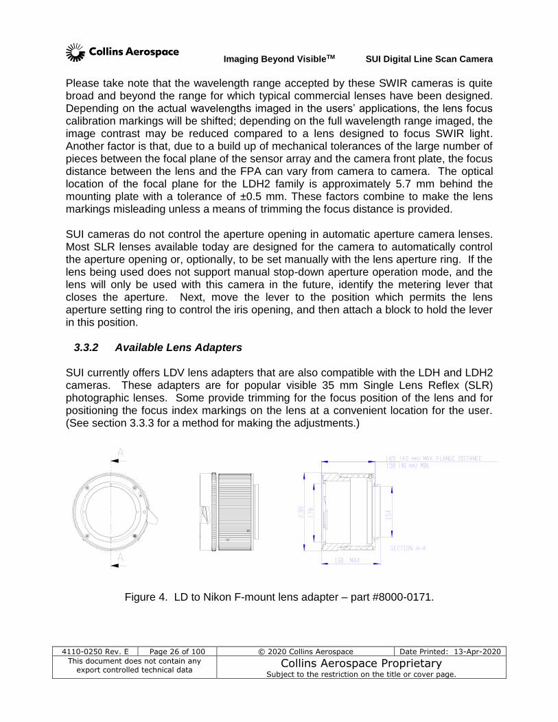
3.3.2 Available Lens Adapters SUI currently offers LDV lens adapters that are also compatible with the LDH and LDH2 cameras. These adapters are for popular visible 35 mm Single Lens Reflex (SLR) photographic lenses. Some provide trimming for the focus position of the lens and for positioning the focus index markings on the lens at a convenient location for the user. (See section 3.3.3 for a method for making the adjustments.)
Figure 4. LD to Nikon F-mount lens adapter – part #8000-0171.
Imaging Beyond VisibleTM SUI Digital Line Scan Camera
4110-0250 Rev. E Page 27 of 100 © 2020 Collins Aerospace Date Printed: 13-Apr-2020
This document does not contain any export controlled technical data
Collins Aerospace Proprietary Subject to the restriction on the title or cover page.
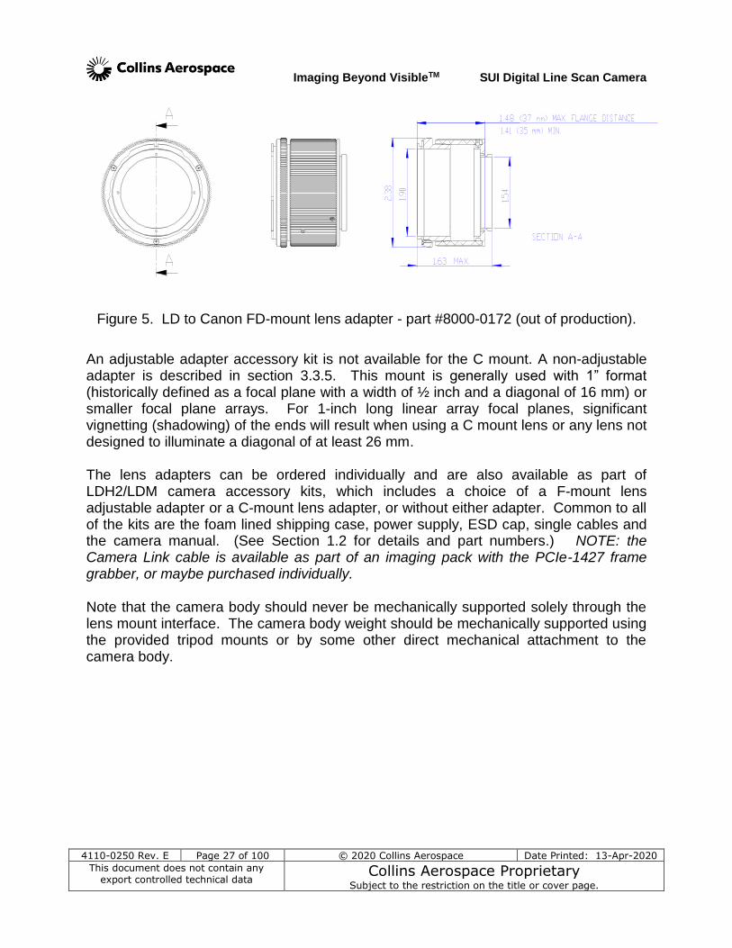
Figure 5. LD to Canon FD-mount lens adapter - part #8000-0172 (out of production).
An adjustable adapter accessory kit is not available for the C mount. A non-adjustable adapter is described in section 3.3.5. This mount is generally used with 1” format (historically defined as a focal plane with a width of ½ inch and a diagonal of 16 mm) or smaller focal plane arrays. For 1-inch long linear array focal planes, significant vignetting (shadowing) of the ends will result when using a C mount lens or any lens not designed to illuminate a diagonal of at least 26 mm. The lens adapters can be ordered individually and are also available as part of LDH2/LDM camera accessory kits, which includes a choice of a F-mount lens adjustable adapter or a C-mount lens adapter, or without either adapter. Common to all of the kits are the foam lined shipping case, power supply, ESD cap, single cables and the camera manual. (See Section 1.2 for details and part numbers.) NOTE: the Camera Link cable is available as part of an imaging pack with the PCIe-1427 frame grabber, or maybe purchased individually. Note that the camera body should never be mechanically supported solely through the lens mount interface. The camera body weight should be mechanically supported using the provided tripod mounts or by some other direct mechanical attachment to the camera body.
Imaging Beyond VisibleTM SUI Digital Line Scan Camera
4110-0250 Rev. E Page 28 of 100 © 2020 Collins Aerospace Date Printed: 13-Apr-2020
This document does not contain any export controlled technical data
Collins Aerospace Proprietary Subject to the restriction on the title or cover page.
3.3.3 Installation of Lens and Adjustable Adapter
1. Choose a dust free environment in which to assemble the camera, lens adapter, and lens. Mount the camera on a tripod or equivalent holder that permits access to the lens adapter set screws all the way around the front of the camera.
2. Inspect the opening in the linear array window for dust or lint. If needed, use clean dry compressed air or follow the cleaning directions in section 1.5.
3. Connect the camera’s Camera Link interface to the computer which will be displaying the data output.
4. Examine the distance markings on the lens. Provide for imaging a target at a distance within the range of the markings on the lens, preferably at a distance from the camera front plate that matches one of the marked distances similar to that being used in the application. If possible, also set up a second target beyond the last distance marking on the lens to approximate infinity. The target should provide sufficient detail at the working distance to make it easy to judge relative focus. As a line scan camera only acquires one line of the image at a time, it can be difficult to recognize what the camera is imaging. It is useful to create a target of vertical bars at a constant spacing or of changing spacing. An example of the latter is known as a Sayce pattern, which can be obtained from sources of line resolution targets.
5. Use a light source similar to that which will be used in the application (e.g., natural lighting, fluorescent, incandescent, or LED). Focus with a monochromic light source will be sharper than with broad wavelength source.
6. Ensure that the lens adapter kit is the appropriate one for the lens to be used and that the lens mates properly with the adapter by temporarily putting them together.
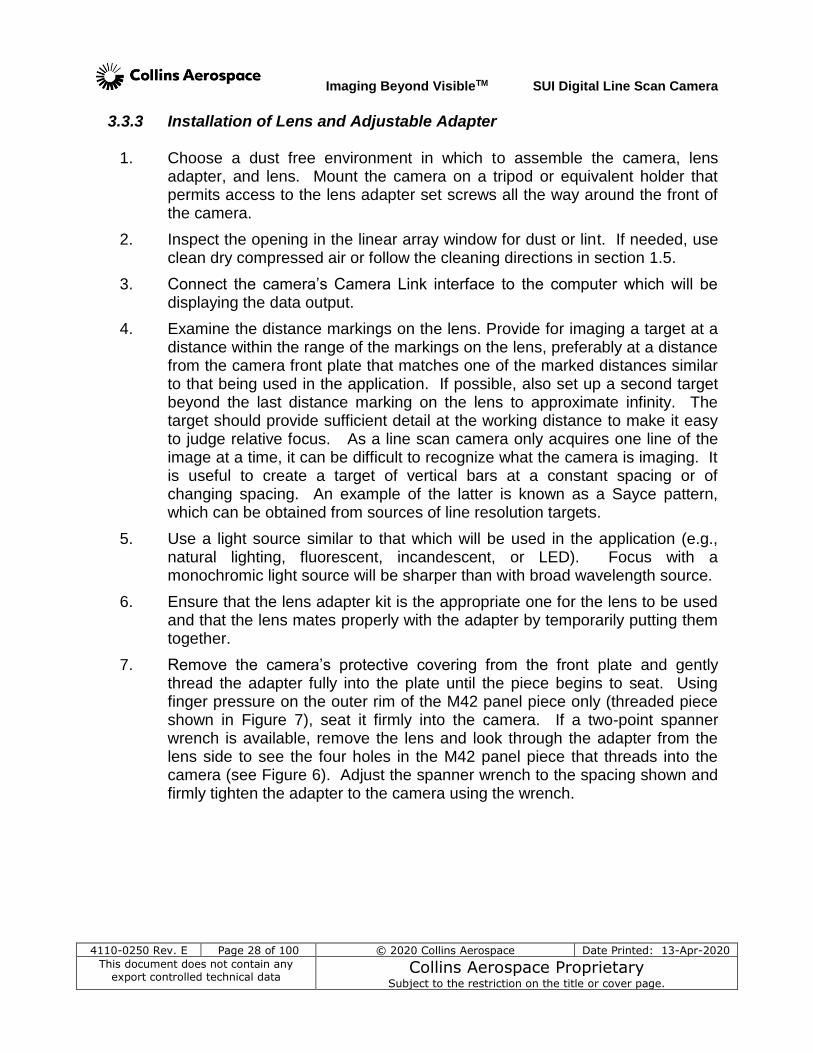
7. Remove the camera’s protective covering from the front plate and gently thread the adapter fully into the plate until the piece begins to seat. Using finger pressure on the outer rim of the M42 panel piece only (threaded piece shown in Figure 7), seat it firmly into the camera. If a two-point spanner wrench is available, remove the lens and look through the adapter from the lens side to see the four holes in the M42 panel piece that threads into the camera (see Figure 6). Adjust the spanner wrench to the spacing shown and firmly tighten the adapter to the camera using the wrench.
Imaging Beyond VisibleTM SUI Digital Line Scan Camera
4110-0250 Rev. E Page 29 of 100 © 2020 Collins Aerospace Date Printed: 13-Apr-2020
This document does not contain any export controlled technical data
Collins Aerospace Proprietary Subject to the restriction on the title or cover page.
Figure 6. Drawing of adapter panel ring showing spanner holes.
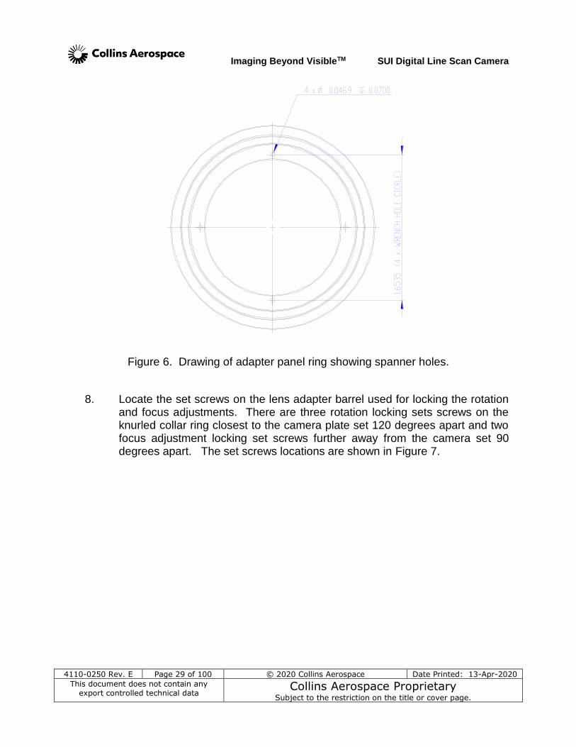
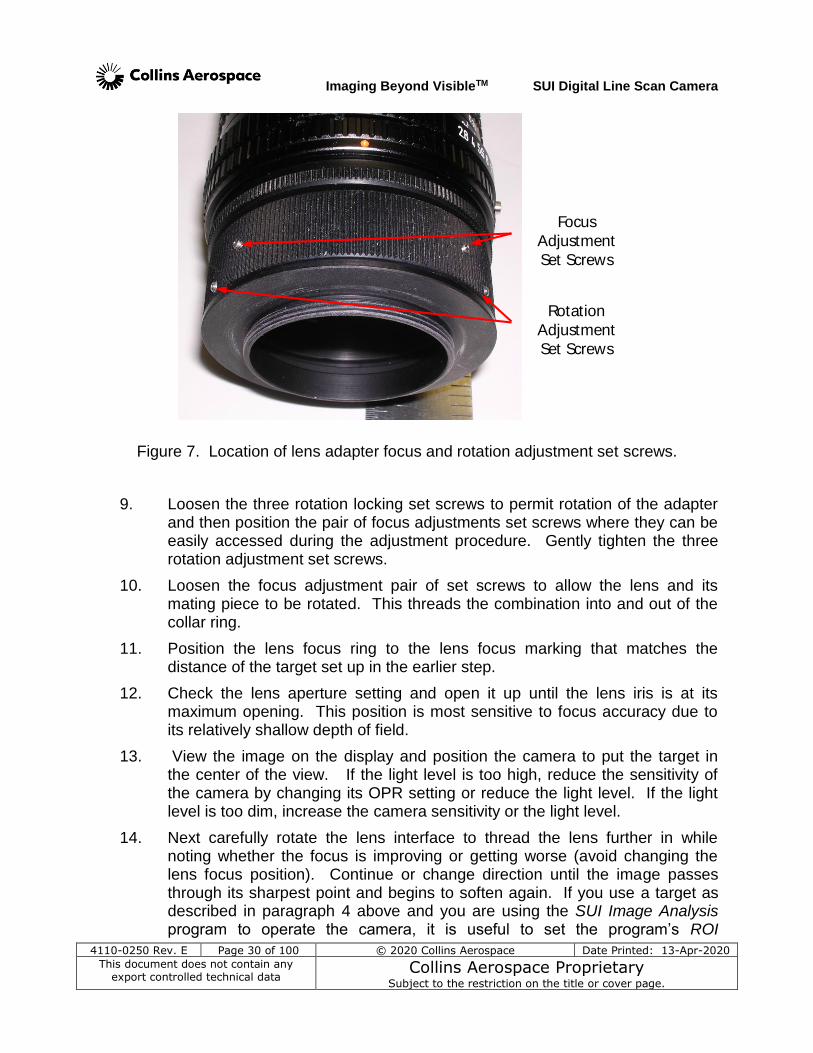
8. Locate the set screws on the lens adapter barrel used for locking the rotation and focus adjustments. There are three rotation locking sets screws on the knurled collar ring closest to the camera plate set 120 degrees apart and two focus adjustment locking set screws further away from the camera set 90 degrees apart. The set screws locations are shown in Figure 7.
Imaging Beyond VisibleTM SUI Digital Line Scan Camera
4110-0250 Rev. E Page 30 of 100 © 2020 Collins Aerospace Date Printed: 13-Apr-2020
This document does not contain any export controlled technical data
Collins Aerospace Proprietary Subject to the restriction on the title or cover page.
Focus
Adjustment
Set Screws
Rotation
Adjustment
Set Screws
Figure 7. Location of lens adapter focus and rotation adjustment set screws.
9. Loosen the three rotation locking set screws to permit rotation of the adapter and then position the pair of focus adjustments set screws where they can be easily accessed during the adjustment procedure. Gently tighten the three rotation adjustment set screws.
10. Loosen the focus adjustment pair of set screws to allow the lens and its mating piece to be rotated. This threads the combination into and out of the collar ring.
11. Position the lens focus ring to the lens focus marking that matches the distance of the target set up in the earlier step.
12. Check the lens aperture setting and open it up until the lens iris is at its maximum opening. This position is most sensitive to focus accuracy due to its relatively shallow depth of field.
13. View the image on the display and position the camera to put the target in the center of the view. If the light level is too high, reduce the sensitivity of the camera by changing its OPR setting or reduce the light level. If the light level is too dim, increase the camera sensitivity or the light level.
14. Next carefully rotate the lens interface to thread the lens further in while noting whether the focus is improving or getting worse (avoid changing the lens focus position). Continue or change direction until the image passes through its sharpest point and begins to soften again. If you use a target as described in paragraph 4 above and you are using the SUI Image Analysis program to operate the camera, it is useful to set the program’s ROI
Imaging Beyond VisibleTM SUI Digital Line Scan Camera
4110-0250 Rev. E Page 31 of 100 © 2020 Collins Aerospace Date Printed: 13-Apr-2020
This document does not contain any export controlled technical data
Collins Aerospace Proprietary Subject to the restriction on the title or cover page.
Measurement Window to the Line Profile tab, with the Line Selection set to Row. Position the image display’s yellow cursor so that it cuts across the black and white squares of the target. Then monitor the peak-to-peak variation of the line profile as you adjust focus. The largest amplitude marks the best focus.
15. Return to the sharpest position, and then check the lens focus marking to ensure that it is correctly positioned.
16. If an alternate target distance is available, shift the camera to view that target and verify the result. Be sure that a satisfactory focus can be achieved at the distant target. It may be necessary to compromise the adapter focus adjustment to give the best average lens marking accuracy between the two points.
17. When satisfied with the adjustment, tighten the focus adjustment set screws (the pair closer to the lens). A torque range of 1-2 in-lbs is recommended for these set screws.
18. Loosen the rotation adjustment set screws (3) and rotate the lens adapter collar ring to reposition the lens focus markings to a position that will be useful when the camera is installed in its normal application. For tripod use with the operator above the camera, this is with the lens markings on top.
19. Retighten the rotation adjustment set screws. A torque range of 1-2 in-lbs is recommended for these set screws.
20. Remove the lens and look through the lens adapter to inspect the surface of the focal plane array. If any dust appears on the array window, follow the instructions of section 1.5 to clean the window. .
3.3.4 Lens Stop-down Mode
Some Canon-FD and Nikon-F lenses support an automatic stop-down feature that is not supported by the SUI LDH2/LDM camera. If using a lens of this type, the lens may require an adjustment or modification to allow manual control of the iris opening. Consult the manufacturer’s documentation for the lens being used to determine the method for operating the lens iris manually. For some lenses, this is accomplished by setting a locking lever on the camera side of the lens.
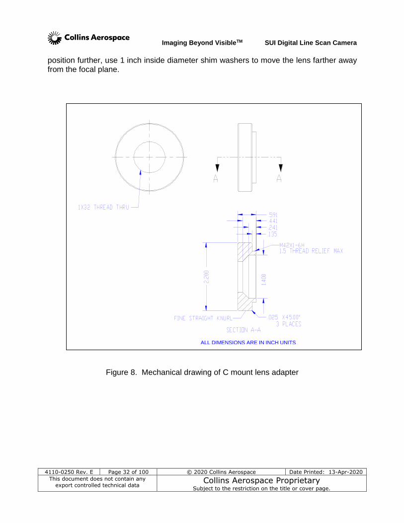
3.3.5 C-Mount Lens Adapter This adapter threads into the M42 threaded hole on the mounting plate and a C-mount lens threads into the 1x32 (M25.4 x 1.26) threaded hole in the adapter. No back focus distance adjustability is provided for this adapter. It is designed to put the lens slightly closer to the focal plane than the C-mount specification of 17.56 mm to ensure that distant objects will achieve focus within their adjustable range. To trim the focus
Imaging Beyond VisibleTM SUI Digital Line Scan Camera
4110-0250 Rev. E Page 32 of 100 © 2020 Collins Aerospace Date Printed: 13-Apr-2020
This document does not contain any export controlled technical data
Collins Aerospace Proprietary Subject to the restriction on the title or cover page.
position further, use 1 inch inside diameter shim washers to move the lens farther away from the focal plane.
Figure 8. Mechanical drawing of C mount lens adapter
ALL DIMENSIONS ARE IN INCH UNITS
Imaging Beyond VisibleTM SUI Digital Line Scan Camera
4110-0250 Rev. E Page 33 of 100 © 2020 Collins Aerospace Date Printed: 13-Apr-2020
This document does not contain any export controlled technical data
Collins Aerospace Proprietary Subject to the restriction on the title or cover page.
4 PRINCIPALS OF OPERATION
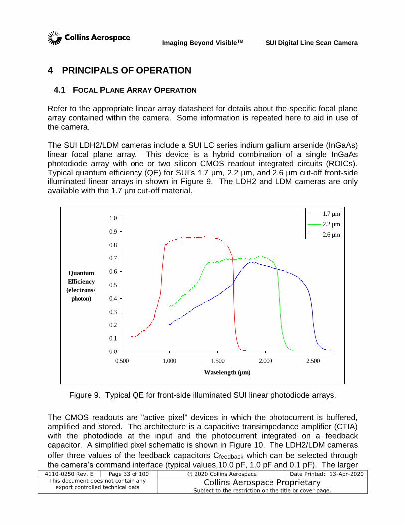
4.1 FOCAL PLANE ARRAY OPERATION Refer to the appropriate linear array datasheet for details about the specific focal plane array contained within the camera. Some information is repeated here to aid in use of the camera. The SUI LDH2/LDM cameras include a SUI LC series indium gallium arsenide (InGaAs) linear focal plane array. This device is a hybrid combination of a single InGaAs photodiode array with one or two silicon CMOS readout integrated circuits (ROICs). Typical quantum efficiency (QE) for SUI’s 1.7 µm, 2.2 µm, and 2.6 µm cut-off front-side illuminated linear arrays in shown in Figure 9. The LDH2 and LDM cameras are only available with the 1.7 µm cut-off material.
0.0
0.1
0.2
0.3
0.4
0.5
0.6
0.7
0.8
0.9
1.0
0.500 1.000 1.500 2.000 2.500
Wavelength (µm)
Quantum
Efficiency
(electrons/
photon)
1.7 µm
2.2 µm
2.6 µm
Figure 9. Typical QE for front-side illuminated SUI linear photodiode arrays.
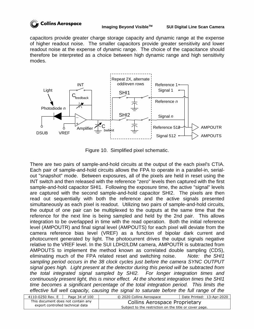
The CMOS readouts are "active pixel" devices in which the photocurrent is buffered, amplified and stored. The architecture is a capacitive transimpedance amplifier (CTIA) with the photodiode at the input and the photocurrent integrated on a feedback capacitor. A simplified pixel schematic is shown in Figure 10. The LDH2/LDM cameras
offer three values of the feedback capacitors Cfeedback which can be selected through
the camera’s command interface (typical values,10.0 pF, 1.0 pF and 0.1 pF). The larger
Imaging Beyond VisibleTM SUI Digital Line Scan Camera
4110-0250 Rev. E Page 34 of 100 © 2020 Collins Aerospace Date Printed: 13-Apr-2020
This document does not contain any export controlled technical data
Collins Aerospace Proprietary Subject to the restriction on the title or cover page.
capacitors provide greater charge storage capacity and dynamic range at the expense of higher readout noise. The smaller capacitors provide greater sensitivity and lower readout noise at the expense of dynamic range. The choice of the capacitance should therefore be interpreted as a choice between high dynamic range and high sensitivity modes.
Figure 10. Simplified pixel schematic.
There are two pairs of sample-and-hold circuits at the output of the each pixel's CTIA. Each pair of sample-and-hold circuits allows the FPA to operate in a parallel-in, serial-out "snapshot" mode. Between exposures, all of the pixels are held in reset using the INT switch and then released with the reference "zero" levels then captured with the first sample-and-hold capacitor SHI1. Following the exposure time, the active "signal" levels are captured with the second sample-and-hold capacitor SHI2. The pixels are then read out sequentially with both the reference and the active signals presented simultaneously as each pixel is readout. Utilizing two pairs of sample-and-hold circuits, the output of one pair can be multiplexed to the outputs at the same time that the reference for the next line is being sampled and held by the 2nd pair. This allows integration to be overlapped in time with the read operation. Both the initial reference level (AMPOUTR) and final signal level (AMPOUTS) for each pixel will deviate from the camera reference bias level (VREF) as a function of bipolar dark current and photocurrent generated by light. The photocurrent drives the output signals negative relative to the VREF level. In the SUI LDH2/LDM camera, AMPOUTR is subtracted from AMPOUTS to implement the method known as correlated double sampling (CDS), eliminating much of the FPA related reset and switching noise. Note: the SHI1 sampling period occurs in the 38 clock cycles just before the camera SYNC OUTPUT signal goes high. Light present at the detector during this period will be subtracted from the total integrated signal sampled by SHI2. For longer integration times and continuously present light, this is minor effect. At the shortest integration times the SHI1 time becomes a significant percentage of the total integration period. This limits the effective full well capacity, causing the signal to saturate before the full range of the
INT
C feedback
Reference n
Amplifier DSUB
Photodiode n
+
–
SHI1
SHI2 Signal n
Light
VREF bwlimit
AMPOUTR
AMPOUTS
Reference 1
Reference 512
Signal 1
Signal 512
C
Repeat 2X, alternate odd/even rows
Imaging Beyond VisibleTM SUI Digital Line Scan Camera
4110-0250 Rev. E Page 35 of 100 © 2020 Collins Aerospace Date Printed: 13-Apr-2020
This document does not contain any export controlled technical data
Collins Aerospace Proprietary Subject to the restriction on the title or cover page.
ADC is reached. The dynamic range values in the specification tables published for the camera reflect this effect. Ideally, there is no bias voltage across the photodiodes. Referring to Figure 10, the level of this zero bias voltage is set at VREF. Due to non-uniformities in the readout circuit, however, the actual bias ΔV across the diodes varies slightly from pixel to pixel. Each pixel exhibits a dark current of ΔI=ΔV/Ro; the input offset voltage of that pixel divided by that pixel's shunt resistance. As ΔV can vary by as much as -3 mV to +3 mV, depending on the operating mode of the FPA, ΔI can be positive or negative causing the digitized dark signal to either increase or decrease with increased exposure time. The average offset across the array is configured such that the digitized dark signal is on scale for all exposure times. At a given temperature and exposure time, this dark current is fixed for each pixel and appears as a spatial fixed pattern noise. Since the shunt resistance, Ro, has a dependence on diode temperature, the dark current signal will change with focal plane array temperature. The SUI LDH2/LDM supports the ability to tightly regulate the FPA temperature over the specified case operating temperature range of the camera. Each CMOS readout device has the ability to multiplex the CTIA outputs through one, two, or four device outputs. Also, one or two readouts may be used in single focal plane array assembly. The SUI LDH2 platform supports operation of LC series FPA assemblies in one, two, or four output mode depending on the particular FPA and camera model selected. If two CMOS readouts are used in the FPA assembly, the readouts are of identical design and receive the same clock timing. The timing sequence of the focal plane array consists of charge integration followed by the readout with the ability to integrate charge for the next line while reading the previous line. The charge on the feedback capacitor is sampled at both the beginning and end of the integration. The duration between two samples is the exposure time, and the difference of the samples is what is digitized to form the digital output of the camera. The camera internally provides all the timing functions for clocking of the focal plane array. The line rate is determined by combining the readout timing requirements and the integration timing requirements. Assuming that the line rate is limited by the readout and not the integration, the maximum line rate is given by the following relationship to the total number of array pixels M, the number of outputs used N, and the pixel readout rate P:
8N
M
PEMAXLINERAT
Imaging Beyond VisibleTM SUI Digital Line Scan Camera
4110-0250 Rev. E Page 36 of 100 © 2020 Collins Aerospace Date Printed: 13-Apr-2020
This document does not contain any export controlled technical data
Collins Aerospace Proprietary Subject to the restriction on the title or cover page.
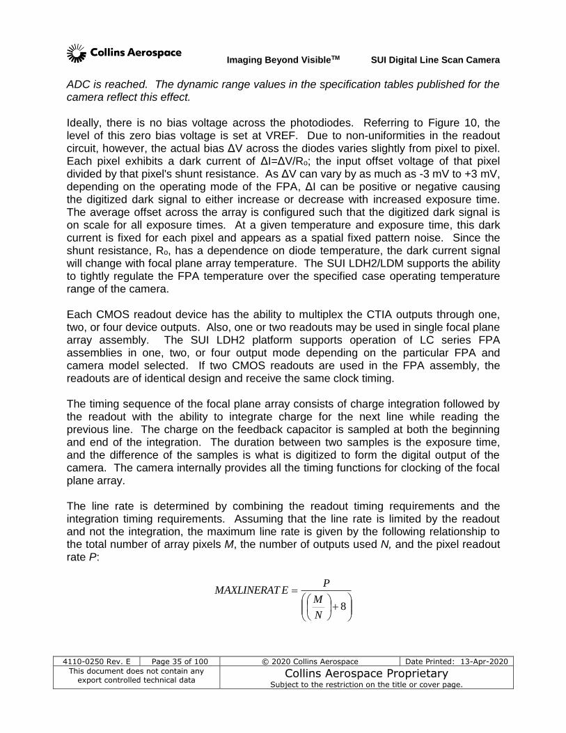
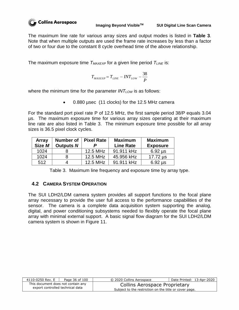
The maximum line rate for various array sizes and output modes is listed in Table 3. Note that when multiple outputs are used the frame rate increases by less than a factor of two or four due to the constant 8 cycle overhead time of the above relationship. The maximum exposure time TMAXEXP for a given line period TLINE is:
PINTTT LOWLINEMAXEXP
38
where the minimum time for the parameter INTLOW is as follows:
0.880 µsec (11 clocks) for the 12.5 MHz camera
For the standard port pixel rate P of 12.5 MHz, the first sample period 38/P equals 3.04 µs. The maximum exposure time for various array sizes operating at their maximum line rate are also listed in Table 3. The minimum exposure time possible for all array sizes is 36.5 pixel clock cycles.
Array Size M
Number of Outputs N
Pixel Rate P
Maximum Line Rate
Maximum Exposure
1024 8 12.5 MHz 91.911 kHz 6.92 µs
1024 8 12.5 MHz 45.956 kHz 17.72 µs
512 4 12.5 MHz 91.911 kHz 6.92 µs
Table 3. Maximum line frequency and exposure time by array type.
4.2 CAMERA SYSTEM OPERATION The SUI LDH2/LDM camera system provides all support functions to the focal plane array necessary to provide the user full access to the performance capabilities of the sensor. The camera is a complete data acquisition system supporting the analog, digital, and power conditioning subsystems needed to flexibly operate the focal plane array with minimal external support. A basic signal flow diagram for the SUI LDH2/LDM camera system is shown in Figure 11.
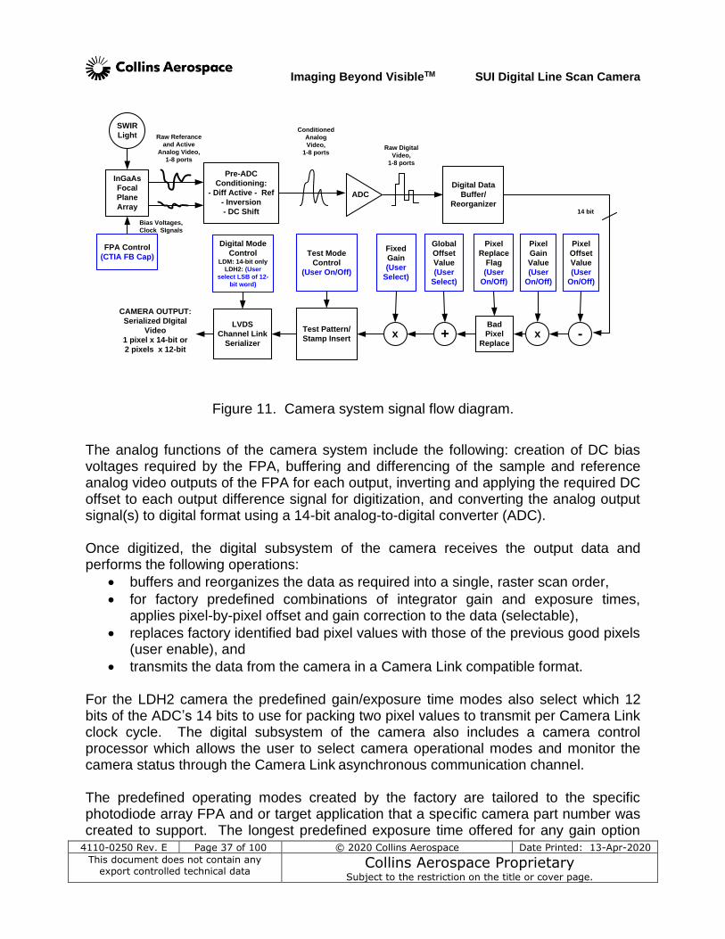
Imaging Beyond VisibleTM SUI Digital Line Scan Camera
4110-0250 Rev. E Page 37 of 100 © 2020 Collins Aerospace Date Printed: 13-Apr-2020
This document does not contain any export controlled technical data
Collins Aerospace Proprietary Subject to the restriction on the title or cover page.
LVDS
Channel Link
Serializer
14 bit
Test Pattern/
Stamp Insert
SWIR
Light
InGaAs
Focal
Plane
Array
Raw Referance
and Active
Analog Video,
1-8 ports
Pre-ADC
Conditioning:
- Diff Active - Ref
- Inversion
- DC Shift
Conditioned
Analog
Video,
1-8 ports
ADC
-x
CAMERA OUTPUT:
Serialized DIgital
Video
1 pixel x 14-bit or
2 pixels x 12-bit
Digital Data
Buffer/
Reorganizer
Raw Digital
Video,
1-8 ports
Fixed
Gain
(User
Select)
Bad
Pixel
Replace+x
Pixel
Replace
Flag
(User
On/Off)
Pixel
Gain
Value
(User
On/Off)
Pixel
Offset
Value
(User
On/Off)
Global
Offset
Value
(User
Select)
FPA Control
(CTIA FB Cap)
Bias Voltages,
Clock SIgnals
Test Mode
Control
(User On/Off)
Digital Mode
ControlLDM: 14-bit only
LDH2: (User
select LSB of 12-
bit word)
Figure 11. Camera system signal flow diagram.
The analog functions of the camera system include the following: creation of DC bias voltages required by the FPA, buffering and differencing of the sample and reference analog video outputs of the FPA for each output, inverting and applying the required DC offset to each output difference signal for digitization, and converting the analog output signal(s) to digital format using a 14-bit analog-to-digital converter (ADC). Once digitized, the digital subsystem of the camera receives the output data and performs the following operations:
buffers and reorganizes the data as required into a single, raster scan order,
for factory predefined combinations of integrator gain and exposure times, applies pixel-by-pixel offset and gain correction to the data (selectable),
replaces factory identified bad pixel values with those of the previous good pixels (user enable), and
transmits the data from the camera in a Camera Link compatible format. For the LDH2 camera the predefined gain/exposure time modes also select which 12 bits of the ADC’s 14 bits to use for packing two pixel values to transmit per Camera Link clock cycle. The digital subsystem of the camera also includes a camera control processor which allows the user to select camera operational modes and monitor the camera status through the Camera Link asynchronous communication channel. The predefined operating modes created by the factory are tailored to the specific photodiode array FPA and or target application that a specific camera part number was created to support. The longest predefined exposure time offered for any gain option
Imaging Beyond VisibleTM SUI Digital Line Scan Camera
4110-0250 Rev. E Page 38 of 100 © 2020 Collins Aerospace Date Printed: 13-Apr-2020
This document does not contain any export controlled technical data
Collins Aerospace Proprietary Subject to the restriction on the title or cover page.
has been choosen to limit + or - dark current from building to a point that might effect performance. The shortest predefined exposure time offered limits the saturation point to levels where internal current flow from the full array is within acceptable limits. Shortening the exposure time to bring such light levels to within the ADC’s range is not advised as the average current will be high if all of the diodes are exposed to the same flux level. To see what exposure time and gain settings are supported by the predefined operation modes, please review Appendix B of the manual where the factory defined modes are listed with their associated settings. A separate document is created for each camera part number and added to the printed manual shipped with the camera. The .PDF image files of the appendix as well as this manual are stored on the data storage media (mini-CD or memory stick) that is also shipped with the camera. This media also holds the camera ICD files and the user program SUI Image Analysis. The factory stored offset and gain corrections are created for each preset integrator gain and exposure time. The offset corrections are stored with the FPA shielded from light. The gain corrections are created by putting the camera front opening against an integrating sphere illuminated with 1550 nm light. Some vignette of the light landing of the 50 pixels on both ends as a result of the limited width of the array window and this is captured in the gain correction. Thus, the corrections provide image non-uniformity correction for the central 90% of the array; the use of the camera gain corrections results in the response of the ends of the array to be over-corrected. The power conditioning subsystem of the camera converts a single DC input power voltage and efficiently re-regulates it to create the power voltages needed internally by the digital and analog subsystems. The power subsystem also includes an adjustable thermoelectric cooler (TEC) power supply, which is under control of the camera’s digital subsystem. A temperature control processor in the camera monitors the FPA temperature and adjusts the TEC power supply as necessary to keep the focal plane array temperature stable. See section 5 for more detailed information on the operation of the various camera functions supported by the SUI LDH2/LDM and the commands used to select the functions.
Imaging Beyond VisibleTM SUI Digital Line Scan Camera
4110-0250 Rev. E Page 39 of 100 © 2020 Collins Aerospace Date Printed: 13-Apr-2020
This document does not contain any export controlled technical data
Collins Aerospace Proprietary Subject to the restriction on the title or cover page.
5 CAMERA FUNCTIONS AND CONTROL SOFTWARE INTERFACE
The SUI LDH2/LDM cameras has a variety of features and modes that can be selected or queried through the control interface including, exposure time, frame rate, sensitivity, corrections, trigger modes, and error status. The SUI LDH2/ LDM cameras communicate via the serial communication provisions of the Camera Link standard. All camera modes are controlled using a set of ASCII commands sent by the Host to the camera.
5.1 COMMUNICATION PROTOCOL The SUI LDH2/LDM cameras communicate via the serial lines provided by the Camera Link interface. This asynchronous serial communication is performed using 8 data bits, 1 stop bit, no parity, no flow control, and a configurable BAUD rate. (See Appendix B for the default serial communication BAUD rate for your particular camera.)
5.2 COMMAND FORMAT AND RESPONSE The following typeface conventions are used when describing the camera command set:
Text that should be reproduced literally is shown in constant-width type.
Text that should be replaced by the user is shown in constant-width italic type.
Optional text is enclosed in square brackets ([]).
Comments are preceded by a double dash (--).
Special operating or cautionary remarks are prefaced by Note: and italicized in the normal font. WARNING notes are in boldface.
When commanding the camera the following rules apply:
Command input is not case sensitive, upper and lowercase characters are accepted by the camera.
A carriage return <CR> ends each command.
All commands and arguments should be separated by white space.
Many commands consist of a main group word, a colon (“:”) and a sub-group; no space should be used between these words.
Extra arguments entered on the command line will be ignored.
The camera supports several echo modes of the characters it receives. The camera can echo the received character back to the user. Alternatively, the echo mode can be configured so that every character received by the camera is echoed using a user-specified character, such as an asterisk. Finally, echo can be disabled, resulting in no output of an echo line.
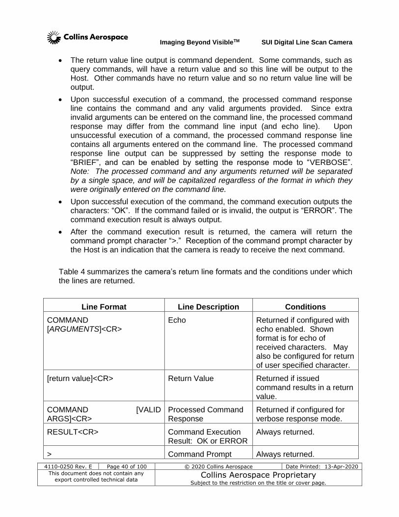
Imaging Beyond VisibleTM SUI Digital Line Scan Camera
4110-0250 Rev. E Page 40 of 100 © 2020 Collins Aerospace Date Printed: 13-Apr-2020
This document does not contain any export controlled technical data
Collins Aerospace Proprietary Subject to the restriction on the title or cover page.
The return value line output is command dependent. Some commands, such as query commands, will have a return value and so this line will be output to the Host. Other commands have no return value and so no return value line will be output.
Upon successful execution of a command, the processed command response line contains the command and any valid arguments provided. Since extra invalid arguments can be entered on the command line, the processed command response may differ from the command line input (and echo line). Upon unsuccessful execution of a command, the processed command response line contains all arguments entered on the command line. The processed command response line output can be suppressed by setting the response mode to “BRIEF”, and can be enabled by setting the response mode to “VERBOSE”. Note: The processed command and any arguments returned will be separated by a single space, and will be capitalized regardless of the format in which they were originally entered on the command line.
Upon successful execution of the command, the command execution outputs the characters: “OK”. If the command failed or is invalid, the output is “ERROR”. The command execution result is always output.
After the command execution result is returned, the camera will return the command prompt character “>.” Reception of the command prompt character by the Host is an indication that the camera is ready to receive the next command.
Table 4 summarizes the camera’s return line formats and the conditions under which the lines are returned.
Line Format Line Description Conditions
COMMAND [ARGUMENTS]<CR>
Echo Returned if configured with echo enabled. Shown format is for echo of received characters. May also be configured for return of user specified character.
[return value]<CR> Return Value Returned if issued command results in a return value.
COMMAND [VALID ARGS]<CR>
Processed Command Response
Returned if configured for verbose response mode.
RESULT<CR> Command Execution Result: OK or ERROR
Always returned.
> Command Prompt Always returned.
Imaging Beyond VisibleTM SUI Digital Line Scan Camera
4110-0250 Rev. E Page 41 of 100 © 2020 Collins Aerospace Date Printed: 13-Apr-2020
This document does not contain any export controlled technical data
Collins Aerospace Proprietary Subject to the restriction on the title or cover page.
Table 4. Line format of camera command return strings.
5.3 STARTUP MESSAGING Reboot of the camera occurs when power to the camera is cycled or the REBOOT command is issued through the command interface (see section 5.4.11.5). Upon reboot, the camera transmits a startup banner to the host. The SUI LDH2 startup banner has the following format:
LDH2 Camera (or LDM Camera) Sensors Unlimited, Inc. Software Version x Memory Map Version y Hardware Version z >
Note: The x, y, and z will be replaced with the letters that correspond to the version of your camera. Once the command prompt character “>” has been received by the Host, the camera is ready to receive a command.
5.4 COMMAND SET Note: For line scan cameras all references to frame(s) in this section refer to a single readout line. A detailed explanation of each command is presented in the following format:
Description Describes the behavior of the command and other pertinent information.
Setting Type Specifies whether the command’s value or function effects a global setting, an operational setting, or neither.
Command Command syntax.
Parameters Lists the parameters taken by the command as listed in the syntax above.
Type Specifies the expected type of the parameter.
Range Specifies the valid range of the parameter.
Return Values Lists the values returned by the command.
Type Specifies the type of the parameter being returned.
Range Specifies the range of the parameter.
Example Provides a programming example, showing the syntax of the command, parameters, and return values. For brevity these
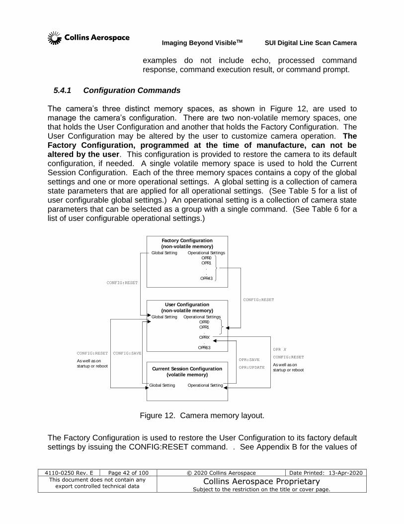
Imaging Beyond VisibleTM SUI Digital Line Scan Camera
4110-0250 Rev. E Page 42 of 100 © 2020 Collins Aerospace Date Printed: 13-Apr-2020
This document does not contain any export controlled technical data
Collins Aerospace Proprietary Subject to the restriction on the title or cover page.
examples do not include echo, processed command response, command execution result, or command prompt.
5.4.1 Configuration Commands
The camera’s three distinct memory spaces, as shown in Figure 12, are used to manage the camera’s configuration. There are two non-volatile memory spaces, one that holds the User Configuration and another that holds the Factory Configuration. The User Configuration may be altered by the user to customize camera operation. The Factory Configuration, programmed at the time of manufacture, can not be altered by the user. This configuration is provided to restore the camera to its default configuration, if needed. A single volatile memory space is used to hold the Current Session Configuration. Each of the three memory spaces contains a copy of the global settings and one or more operational settings. A global setting is a collection of camera state parameters that are applied for all operational settings. (See Table 5 for a list of user configurable global settings.) An operational setting is a collection of camera state parameters that can be selected as a group with a single command. (See Table 6 for a list of user configurable operational settings.)
Factory Configuration
(non-volatile memory)
User Configuration
(non-volatile memory)
Current Session Configuration
(volatile memory)
Global Setting Operational Setting
Global Setting Operational Settings
OPR0
OPR1.
OPRX
.
OPR63
Global Setting Operational Settings
OPR0OPR1
.
.
OPR43
OPR:SAVE
OPR:UPDATE
CONFIG:RESET
CONFIG:RESET
CONFIG:SAVEOPR X
CONFIG:RESET
As well as on
startup or reboot
CONFIG:RESET
As well as on
startup or reboot
Figure 12. Camera memory layout.
The Factory Configuration is used to restore the User Configuration to its factory default settings by issuing the CONFIG:RESET command. . See Appendix B for the values of

Imaging Beyond VisibleTM SUI Digital Line Scan Camera
4110-0250 Rev. E Page 43 of 100 © 2020 Collins Aerospace Date Printed: 13-Apr-2020
This document does not contain any export controlled technical data
Collins Aerospace Proprietary Subject to the restriction on the title or cover page.
the Factory Configuration global and operational parameters of the camera associated with this manual. Both the User and Factory Configurations contain one global setting and multiple operational settings. The User Configuration is loaded into the Current Session Configuration upon camera power-up. The User Configuration can be modified by issuing the CONFIG:SAVE command, which causes the global setting in the Current Session to be written back to the User Configuration, overwriting the previous global setting. Issuing the OPR:SAVE command results in the creation of a new operational slot in the User Configuration. The present state of the operational setting in the Current Session Configuration is saved to this newly created operational slot. Issuing the OPR:UPDATE command causes the operational settings in the Current Session Configuration to be written back to the User Configuration, overwriting the previous settings for that particular operational slot. The Current Session Configuration provides space to hold one global setting and one operational setting. Different operational settings can be loaded into the Current Session Configuration with the OPR command. Once the global and operational settings are loaded they can be modified by issuing commands to the camera. Changes to the operational and/or global settings will not persist between camera power cycles unless they are saved to User Configuration non-volatile memory space using the OPR:UPDATE or OPR:SAVE commands followed by the CONFIG:SAVE command after any changes the user intends the camera to use on power up.
Communication BAUD Rate
Communication Echo Mode
Communication Echo Character
Response Mode
Gain Correction
Offset Correction
Defect Pixel Correction
Global Corrected Offset
Digital Gain
Scan State
Over-Scan State
Test Pattern
Frame Stamp
Trigger Mode
Trigger Source
Trigger Polarity
Trigger Delay
Startup Operational Slot
Table 5. User configurable global settings.
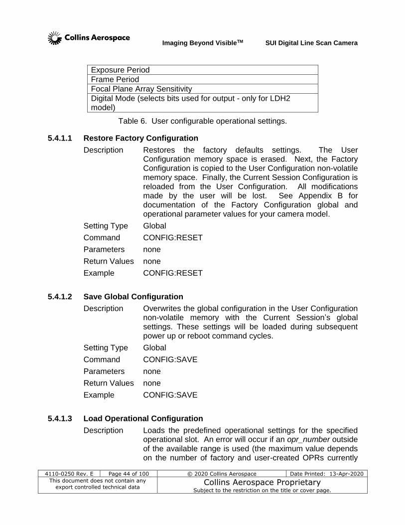
Imaging Beyond VisibleTM SUI Digital Line Scan Camera
4110-0250 Rev. E Page 44 of 100 © 2020 Collins Aerospace Date Printed: 13-Apr-2020
This document does not contain any export controlled technical data
Collins Aerospace Proprietary Subject to the restriction on the title or cover page.
Exposure Period
Frame Period
Focal Plane Array Sensitivity
Digital Mode (selects bits used for output - only for LDH2 model)
Table 6. User configurable operational settings.
5.4.1.1 Restore Factory Configuration
Description Restores the factory defaults settings. The User Configuration memory space is erased. Next, the Factory Configuration is copied to the User Configuration non-volatile memory space. Finally, the Current Session Configuration is reloaded from the User Configuration. All modifications made by the user will be lost. See Appendix B for documentation of the Factory Configuration global and operational parameter values for your camera model.
Setting Type Global
Command CONFIG:RESET
Parameters none
Return Values none
Example CONFIG:RESET
5.4.1.2 Save Global Configuration
Description Overwrites the global configuration in the User Configuration non-volatile memory with the Current Session’s global settings. These settings will be loaded during subsequent power up or reboot command cycles.
Setting Type Global
Command CONFIG:SAVE
Parameters none
Return Values none
Example CONFIG:SAVE
5.4.1.3 Load Operational Configuration
Description Loads the predefined operational settings for the specified operational slot. An error will occur if an opr_number outside of the available range is used (the maximum value depends on the number of factory and user-created OPRs currently
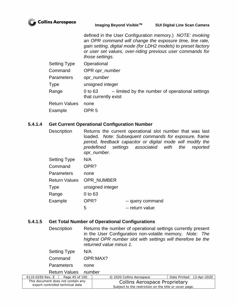
Imaging Beyond VisibleTM SUI Digital Line Scan Camera
4110-0250 Rev. E Page 45 of 100 © 2020 Collins Aerospace Date Printed: 13-Apr-2020
This document does not contain any export controlled technical data
Collins Aerospace Proprietary Subject to the restriction on the title or cover page.
defined in the User Configuration memory.) NOTE: invoking an OPR command will change the exposure time, line rate, gain setting, digital mode (for LDH2 models) to preset factory or user set values, over-riding previous user commands for those settings.
Setting Type Operational
Command OPR opr_number
Parameters opr_number
Type unsigned integer
Range 0 to 63 -- limited by the number of operational settings that currently exist
Return Values none
Example OPR 5
5.4.1.4 Get Current Operational Configuration Number
Description Returns the current operational slot number that was last loaded. Note: Subsequent commands for exposure, frame period, feedback capacitor or digital mode will modify the predefined settings associated with the reported opr_number.
Setting Type N/A
Command OPR?
Parameters none
Return Values OPR_NUMBER
Type unsigned integer
Range 0 to 63
Example OPR? -- query command
5 -- return value
5.4.1.5 Get Total Number of Operational Configurations
Description Returns the number of operational settings currently present in the User Configuration non-volatile memory. Note: The highest OPR number slot with settings will therefore be the returned value minus 1.
Setting Type N/A
Command OPR:MAX?
Parameters none
Return Values number
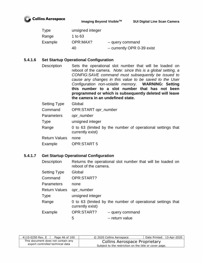
Imaging Beyond VisibleTM SUI Digital Line Scan Camera
4110-0250 Rev. E Page 46 of 100 © 2020 Collins Aerospace Date Printed: 13-Apr-2020
This document does not contain any export controlled technical data
Collins Aerospace Proprietary Subject to the restriction on the title or cover page.
Type unsigned integer
Range 1 to 63
Example OPR:MAX? -- query command
40 -- currently OPR 0-39 exist
5.4.1.6 Set Startup Operational Configuration
Description Sets the operational slot number that will be loaded on reboot of the camera. Note: since this is a global setting, a CONFIG:SAVE command must subsequently be issued to cause any changes in this value to be saved to the User Configuration non-volatile memory. WARNING: Setting this number to a slot number that has not been programmed or which is subsequently deleted will leave the camera in an undefined state.
Setting Type Global
Command OPR:START opr_number
Parameters opr_number
Type unsigned integer
Range 0 to 63 (limited by the number of operational settings that currently exist)
Return Values none
Example OPR:START 5
5.4.1.7 Get Startup Operational Configuration
Description Returns the operational slot number that will be loaded on reboot of the camera.
Setting Type Global
Command OPR:START?
Parameters none
Return Values opr_number
Type unsigned integer
Range 0 to 63 (limited by the number of operational settings that currently exist)
Example OPR:START? -- query command
5 -- return value
Imaging Beyond VisibleTM SUI Digital Line Scan Camera
4110-0250 Rev. E Page 47 of 100 © 2020 Collins Aerospace Date Printed: 13-Apr-2020
This document does not contain any export controlled technical data
Collins Aerospace Proprietary Subject to the restriction on the title or cover page.
5.4.1.8 Create New Operational Configuration
Description Takes the Current Session operational settings and saves them to User Configuration non-volatile memory and assigns a new operational slot number. A maximum of 64 operational slots are allowed and the operational slot numbers are assigned sequentially. The new operational slot number will be returned to the host. It is possible with this tool to duplicate existing OPR configurations into another slot. Note when a new operational configuration is created, any factory correction table associated with the existing operational configuration will not be copied to the new operational configuration slot. Corrections, therefore, must be disabled when using the newly created configuration slot for meaningful data to be produced.
Setting Type Operational
Command OPR:SAVE
Parameters none
Return Values New OPR Number = opr_number
Type unsigned integer
Range 0 to 63 -- an error message will be issued if all available slots are used
Example OPR:SAVE -- command
45 -- return value
5.4.1.9 Update Existing Operational Configuration
Description Overwrites the current operational configuration in the User Configuration non-volatile memory with the operational settings from the Current Session Configuration. In this manner, the total number of OPR configurations does not increase by one, and a configuration is saved to a known user slot. It is possible to temporarily overwrite a factory parameter slot; the factory definitions can be restored via CONFIG:RESET.
Setting Type Operational
Command OPR:UPDATE
Parameters none
Return Values none
Example OPR:UPDATE
Imaging Beyond VisibleTM SUI Digital Line Scan Camera
4110-0250 Rev. E Page 48 of 100 © 2020 Collins Aerospace Date Printed: 13-Apr-2020
This document does not contain any export controlled technical data
Collins Aerospace Proprietary Subject to the restriction on the title or cover page.
5.4.1.10 Delete Last Operational Configuration
Description Deletes the last, and therefore highest slot number, operational configuration from the User Configuration non-volatile memory. This operation will only delete operational configuration slots created by the user, and will return an error if executed when only factory operational configuration slots exist. If the Current Session Configuration is the last operational configuration when this command is issued, a subsequent query of the current operational configuration number will return the deleted operational configuration number, since it is still the Current Session Configuration, but a command to load the deleted operational number will error. WARNING: If the startup operational configuration is deleted, the camera operation is no longer specified. Use the OPR:START followed by the CONFIG:SAVE commands to reselect an existing operational configuration slot if the startup operational configuration slot is deleted.
Setting Type Operational
Command OPR:DEL
Parameters none
Return Values none
Example OPR:DEL
5.4.1.11 Delete All Operational Configurations
Description Deletes all operational configuration slots created by the user from the User Configuration non-volatile memory. This operation will return an error if executed when only factory operational configuration slots exist. If the Current Session Configuration slot is deleted from the User Configuration memory, a subsequent query of the current operational configuration number will return the deleted operational configuration number, since it is still the Current Session Configuration, but a command to load the deleted operational number will return an error. WARNING: If the startup operational configuration is deleted, the camera operation is no longer specified. Use the OPR:START followed by the CONFIG:SAVE commands to reselect an existing operational configuration slot if the startup operational configuration slot is deleted.
Setting Type Operational
Command OPR:DEL:ALL
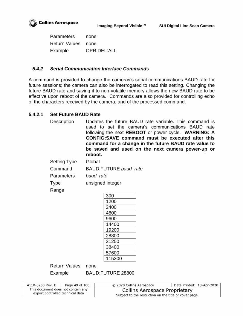
Imaging Beyond VisibleTM SUI Digital Line Scan Camera
4110-0250 Rev. E Page 49 of 100 © 2020 Collins Aerospace Date Printed: 13-Apr-2020
This document does not contain any export controlled technical data
Collins Aerospace Proprietary Subject to the restriction on the title or cover page.
Parameters none
Return Values none
Example OPR:DEL:ALL
5.4.2 Serial Communication Interface Commands A command is provided to change the cameras’s serial communications BAUD rate for future sessions; the camera can also be interrogated to read this setting. Changing the future BAUD rate and saving it to non-volatile memory allows the new BAUD rate to be effective upon reboot of the camera. Commands are also provided for controlling echo of the characters received by the camera, and of the processed command.
5.4.2.1 Set Future BAUD Rate
Description Updates the future BAUD rate variable. This command is used to set the camera’s communications BAUD rate following the next REBOOT or power cycle. WARNING: A CONFIG:SAVE command must be executed after this command for a change in the future BAUD rate value to be saved and used on the next camera power-up or reboot.
Setting Type Global
Command BAUD:FUTURE baud_rate
Parameters baud_rate
Type unsigned integer
Range
300
1200
2400
4800
9600
14400
19200
28800
31250
38400
57600
115200
Return Values none
Example BAUD:FUTURE 28800
Imaging Beyond VisibleTM SUI Digital Line Scan Camera
4110-0250 Rev. E Page 50 of 100 © 2020 Collins Aerospace Date Printed: 13-Apr-2020
This document does not contain any export controlled technical data
Collins Aerospace Proprietary Subject to the restriction on the title or cover page.
5.4.2.2 Get Future BAUD Rate
Description Returns the value stored in the future BAUD rate variable.
Setting Type Global
Command BAUD:FUTURE?
Parameters none
Return Values baud_rate
Type unsigned integer
Range
300
1200
2400
4800
9600
14400
19200
28800
31250
38400
57600
115200
Example BAUD:FUTURE? -- query command
28800 -- return value
5.4.2.3 Set Echo Mode
Description Sets the echo mode for serial communications. In mode 0 echo is disabled. In mode 1 echo is enabled and any character received on the serial port is immediately echoed back. An exception to the echo of the received character with mode 1 enabled is when a backspace character is received while the receive buffer is empty. In mode 2 echo is enabled but instead of echoing back the character received a user defined character is echoed. Echo mode 1 provides for the most robust communication, allowing the host to verify that each character sent to the camera was properly received. Echo mode 2 allows the host to verify that the camera received the correct number of characters, but does not provide a way to verify that characters where not corrupted during transmission.
Setting Type Global
Command ECHO:MODE mode
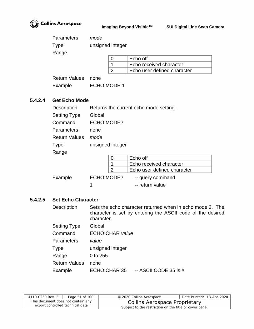
Imaging Beyond VisibleTM SUI Digital Line Scan Camera
4110-0250 Rev. E Page 51 of 100 © 2020 Collins Aerospace Date Printed: 13-Apr-2020
This document does not contain any export controlled technical data
Collins Aerospace Proprietary Subject to the restriction on the title or cover page.
Parameters mode
Type unsigned integer
Range
0 Echo off
1 Echo received character
2 Echo user defined character
Return Values none
Example ECHO:MODE 1
5.4.2.4 Get Echo Mode
Description Returns the current echo mode setting.
Setting Type Global
Command ECHO:MODE?
Parameters none
Return Values mode
Type unsigned integer
Range
0 Echo off
1 Echo received character
2 Echo user defined character
Example ECHO:MODE? -- query command
1 -- return value
5.4.2.5 Set Echo Character
Description Sets the echo character returned when in echo mode 2. The character is set by entering the ASCII code of the desired character.
Setting Type Global
Command ECHO:CHAR value
Parameters value
Type unsigned integer
Range 0 to 255
Return Values none
Example ECHO:CHAR 35 -- ASCII CODE 35 is #
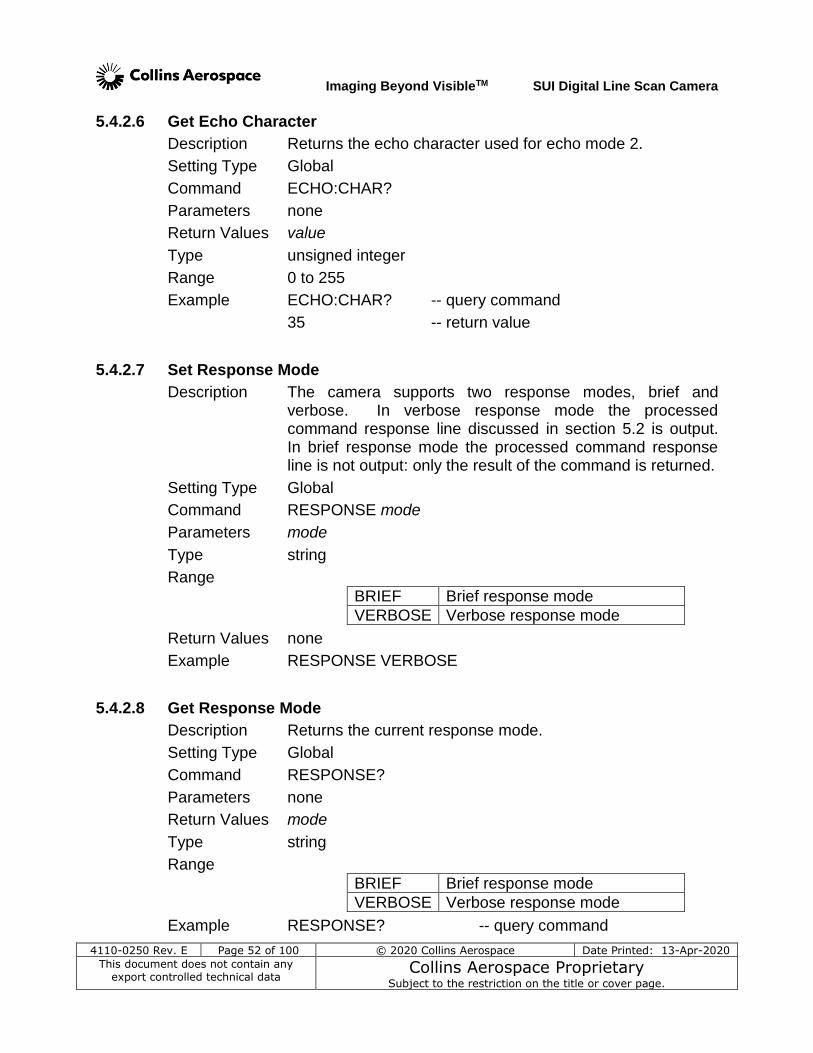
Imaging Beyond VisibleTM SUI Digital Line Scan Camera
4110-0250 Rev. E Page 52 of 100 © 2020 Collins Aerospace Date Printed: 13-Apr-2020
This document does not contain any export controlled technical data
Collins Aerospace Proprietary Subject to the restriction on the title or cover page.
5.4.2.6 Get Echo Character
Description Returns the echo character used for echo mode 2.
Setting Type Global
Command ECHO:CHAR?
Parameters none
Return Values value
Type unsigned integer
Range 0 to 255
Example ECHO:CHAR? -- query command
35 -- return value
5.4.2.7 Set Response Mode
Description The camera supports two response modes, brief and verbose. In verbose response mode the processed command response line discussed in section 5.2 is output. In brief response mode the processed command response line is not output: only the result of the command is returned.
Setting Type Global
Command RESPONSE mode
Parameters mode
Type string
Range
BRIEF Brief response mode
VERBOSE Verbose response mode
Return Values none
Example RESPONSE VERBOSE
5.4.2.8 Get Response Mode
Description Returns the current response mode.
Setting Type Global
Command RESPONSE?
Parameters none
Return Values mode
Type string
Range
BRIEF Brief response mode
VERBOSE Verbose response mode
Example RESPONSE? -- query command
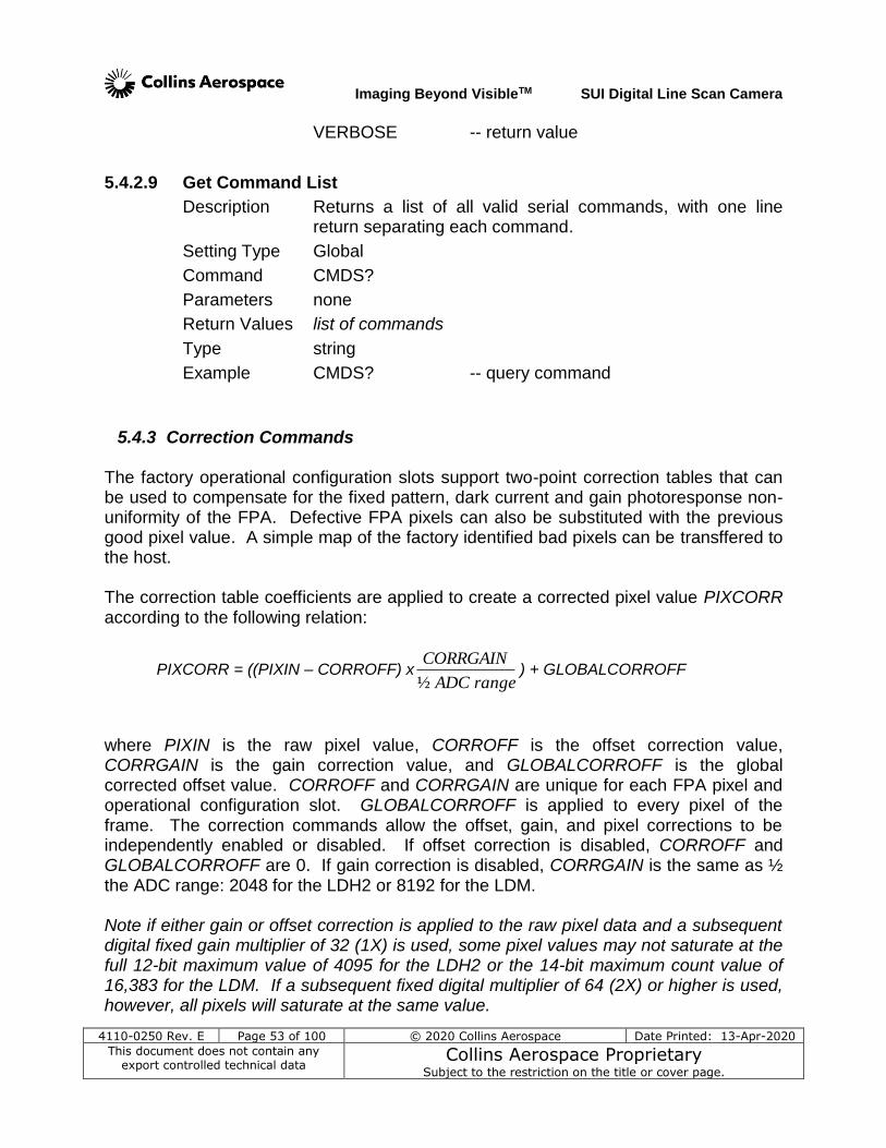
Imaging Beyond VisibleTM SUI Digital Line Scan Camera
4110-0250 Rev. E Page 53 of 100 © 2020 Collins Aerospace Date Printed: 13-Apr-2020
This document does not contain any export controlled technical data
Collins Aerospace Proprietary Subject to the restriction on the title or cover page.
VERBOSE -- return value
5.4.2.9 Get Command List
Description Returns a list of all valid serial commands, with one line return separating each command.
Setting Type Global
Command CMDS?
Parameters none
Return Values list of commands
Type string
Example CMDS? -- query command
5.4.3 Correction Commands The factory operational configuration slots support two-point correction tables that can be used to compensate for the fixed pattern, dark current and gain photoresponse non-uniformity of the FPA. Defective FPA pixels can also be substituted with the previous good pixel value. A simple map of the factory identified bad pixels can be transffered to the host. The correction table coefficients are applied to create a corrected pixel value PIXCORR according to the following relation:
PIXCORR = ((PIXIN – CORROFF) xrangeADC
CORRGAIN
½) + GLOBALCORROFF
where PIXIN is the raw pixel value, CORROFF is the offset correction value, CORRGAIN is the gain correction value, and GLOBALCORROFF is the global corrected offset value. CORROFF and CORRGAIN are unique for each FPA pixel and operational configuration slot. GLOBALCORROFF is applied to every pixel of the frame. The correction commands allow the offset, gain, and pixel corrections to be independently enabled or disabled. If offset correction is disabled, CORROFF and GLOBALCORROFF are 0. If gain correction is disabled, CORRGAIN is the same as ½ the ADC range: 2048 for the LDH2 or 8192 for the LDM. Note if either gain or offset correction is applied to the raw pixel data and a subsequent digital fixed gain multiplier of 32 (1X) is used, some pixel values may not saturate at the full 12-bit maximum value of 4095 for the LDH2 or the 14-bit maximum count value of 16,383 for the LDM. If a subsequent fixed digital multiplier of 64 (2X) or higher is used, however, all pixels will saturate at the same value.
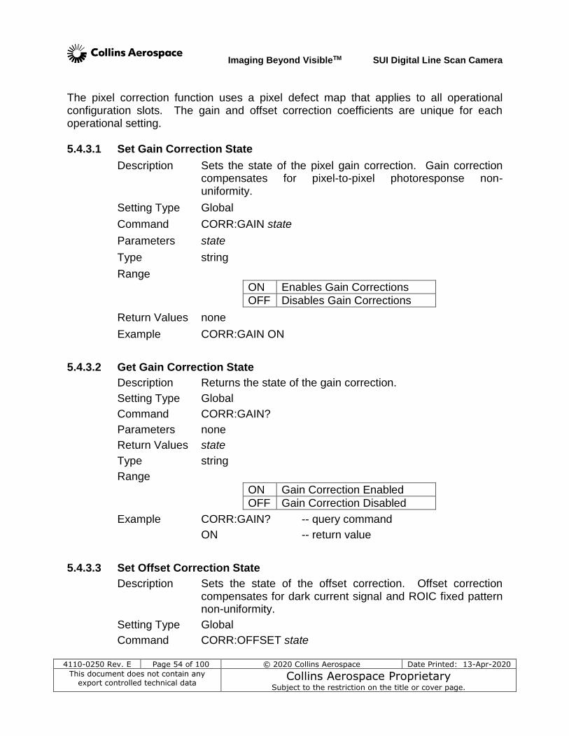
Imaging Beyond VisibleTM SUI Digital Line Scan Camera
4110-0250 Rev. E Page 54 of 100 © 2020 Collins Aerospace Date Printed: 13-Apr-2020
This document does not contain any export controlled technical data
Collins Aerospace Proprietary Subject to the restriction on the title or cover page.
The pixel correction function uses a pixel defect map that applies to all operational configuration slots. The gain and offset correction coefficients are unique for each operational setting. 5.4.3.1 Set Gain Correction State
Description Sets the state of the pixel gain correction. Gain correction compensates for pixel-to-pixel photoresponse non-uniformity.
Setting Type Global
Command CORR:GAIN state
Parameters state
Type string
Range
ON Enables Gain Corrections
OFF Disables Gain Corrections
Return Values none
Example CORR:GAIN ON
5.4.3.2 Get Gain Correction State
Description Returns the state of the gain correction.
Setting Type Global
Command CORR:GAIN?
Parameters none
Return Values state
Type string
Range
ON Gain Correction Enabled
OFF Gain Correction Disabled
Example CORR:GAIN? -- query command
ON -- return value
5.4.3.3 Set Offset Correction State
Description Sets the state of the offset correction. Offset correction compensates for dark current signal and ROIC fixed pattern non-uniformity.
Setting Type Global
Command CORR:OFFSET state
Imaging Beyond VisibleTM SUI Digital Line Scan Camera
4110-0250 Rev. E Page 55 of 100 © 2020 Collins Aerospace Date Printed: 13-Apr-2020
This document does not contain any export controlled technical data
Collins Aerospace Proprietary Subject to the restriction on the title or cover page.
Parameters state
Type string
Range
ON Enables Offset Corrections
OFF Disables Offset Corrections
Return Values none
Example CORR:OFFSET ON
5.4.3.4 Get Offset Correction State
Description Returns the state of the offset correction.
Setting Type Global
Command CORR:OFFSET?
Parameters none
Return Values state
Type string
Range
ON Offset Correction Enabled
OFF Offset Correction Disabled
Example CORR:OFFSET? -- query command
ON -- return value
5.4.3.5 Set Pixel Correction State
Description Sets the state of the bad pixel correction. Pixel correction replaces pixels that do not pass focal plane array performance specifications with the previous, non-replaced pixel value. Note: if the first pixel of the array output is classified as bad, the value substituted will be from a non-active pixel location and will be near zero.
Setting Type Global
Command CORR:PIXEL state
Parameters state
Type string
Range
ON Enables Pixel Corrections
OFF Disables Pixel Corrections
Return Values none
Example CORR:PIXEL ON
Imaging Beyond VisibleTM SUI Digital Line Scan Camera
4110-0250 Rev. E Page 56 of 100 © 2020 Collins Aerospace Date Printed: 13-Apr-2020
This document does not contain any export controlled technical data
Collins Aerospace Proprietary Subject to the restriction on the title or cover page.
5.4.3.6 Get Pixel Correction State
Description Returns the state of the pixel correction.
Setting Type Global
Command CORR:PIXEL?
Parameters none
Return Values state
Type string
Range
ON Pixel Correction Enabled
OFF Pixel Correction Disabled
Example CORR:PIXEL? -- query command
ON -- return value
5.4.3.7 Set Global Corrected Offset Value
Description Sets the global offset value. Global offset is a DC level that is added to each pixel in the image after all other corrections have been applied and only when offset correction is enabled. Adding an offset is important when line averaging as it prevents clipping of negative-going noise excursions. Such clipping would distort the average. The global offset can be disabled by setting its value to 0 (zero). Note: The offset programmed by this command will be scaled by the setting of the GAIN:DIGITAL commands, e.g, a global offset of 100 counts will become 200 counts if the digital gain is set to 2X and it will also be factored by the DIGITAL:MODE setting for the LDH2.
Setting Type Global
Command CORR:OFFSET:GLOBAL value
Parameters value
Type unsigned integer
Range 0 to 4095 for LDH2, to 16383 for LDM
Return Values none
Example CORR:OFFSET:GLOBAL 200
5.4.3.8 Get Global Corrected Offset Value
Description Returns the global offset value.
Setting Type Global
Command CORR:OFFSET:GLOBAL?
Parameters none
Imaging Beyond VisibleTM SUI Digital Line Scan Camera
4110-0250 Rev. E Page 57 of 100 © 2020 Collins Aerospace Date Printed: 13-Apr-2020
This document does not contain any export controlled technical data
Collins Aerospace Proprietary Subject to the restriction on the title or cover page.
Return Values value
Type unsigned integer
Range 0 to 4095 for LDH2, to 16383 for LDM
Example CORR:OFFSET:GLOBAL? -- query command
200 -- return value
0 -- return value (disabled)
5.4.3.9 Set Pixel Map State
Description Enables/disables display of bad pixel map (0 count value for used pixels, 4095 if pixel has been flagged as bad) in place of corrected image data. Note: This map will continue to be transmitted until turned off.
Setting Type Global
Command CORR:PIXEL:MAP state
Parameters state
Type string
Range
ON Enables Pixel Map
OFF Disables Pixel Map
Return Values none
Example CORR:PIXEL ON
5.4.3.10 Get Pixel Map State
Description Returns the state of the pixel map.
Setting Type Global
Command CORR:PIXEL:MAP?
Parameters none
Return Values state
Type string
Range
ON Pixel Map Enabled
OFF Pixel Map Disabled
Example CORR:PIXEL:MAP? -- query command
OFF -- return value
Imaging Beyond VisibleTM SUI Digital Line Scan Camera
4110-0250 Rev. E Page 58 of 100 © 2020 Collins Aerospace Date Printed: 13-Apr-2020
This document does not contain any export controlled technical data
Collins Aerospace Proprietary Subject to the restriction on the title or cover page.
5.4.4 Pixel Clock Command The LDH/LDM camera electronics are designed to support the lattice matched InGaAs linear arrays with the LC ROIC, which have a wavelength response cutoff near 1.7 µm and a readout clock rate of 12.5 MHz per port. Therefore, the pixel clock rate is configured by the factory and cannot be modified, nor is there an option to divide the clock rate down. For compatibility with customer software that supports other SUI camera models, which may use other clock rates, the query command for the camera clock rate is provided below. The values needed to calculate the pixel clock rate can be queried using the commands below. The pixel clock period is needed to calculate exposure and frame times. 5.4.4.1 Get Pixel Clock Maximum Rate
Description Returns the pixel clock rate in Hertz used by the LDH2/LDM camera electronics. This value is set by hardware design and the command provided for compatibility with software written for other SUI line scan camera models.
Setting Type Global
Command PIXCLK:MAX?
Parameters none
Return Values value
Type unsigned integer
Range 0 to 4294967295
Example PIXCLK:MAX? -- query command
12500000 -- return value
5.4.5 Frame and Exposure Control Commands The internally timed exposure period can be calculated using the following equations:
5.38 EXPSETTINGEXPCYCLES where EXPSETTING is the exposure period set using the EXP command. For a particular number of exposure clock cycles EXPCYCLES, the resulting exposure period time EXPPERIOD is as follows:
DPIXELPERIOEXPCYCLESEXPPERIOD
Imaging Beyond VisibleTM SUI Digital Line Scan Camera
4110-0250 Rev. E Page 59 of 100 © 2020 Collins Aerospace Date Printed: 13-Apr-2020
This document does not contain any export controlled technical data
Collins Aerospace Proprietary Subject to the restriction on the title or cover page.
The internally timed frame period is given by:
DPIXELPERIOSFRAMECYCLEDFRAMEPERIO where FRAMEPERIOD is the frame period set using the FRAME:PERIOD command to specify the number of FRAMECYCLES to be used. See section 4.1 for a discussion on the minimum frame period for a given exposure period and readout type. See section 5.4.4 for a discussion on calculating the pixel clock period. Note: When scanning is enabled the exposure period and frame period specified must be compatible with each other or a command error will occur. Therefore, knowledge of the current exposure and frame periods is required and the order in which the exposure and frame period are changed is important for avoiding errors. Going from a short exposure and frame period to a longer exposure and frame period requires first increasing the frame period, and then the exposure period, while going in the opposite direction requires shortening the exposure period first. To avoid issues regarding which setting to update first, scanning can be disabled. Once scanning is disabled, the exposure and frame periods may be set in any order and then scanning may be re-enabled. However, exposure and frame periods compatible with each other and the timing requirements of the FPA must be specified, otherwise, an error will be returned when attempting to enable scanning. Note: When the camera is set to operate in an externally triggered timing, the exposure and frame period settings may not apply. (See section 5.4.6 for a description of supported triggered timing modes.) Note: Though the camera digital command system supports setting very long exposure times, dark current will limit the longest effective exposure time. It is not recommended to use exposure times which result in dark current exceeeding 10% of the full scale capacity.
Imaging Beyond VisibleTM SUI Digital Line Scan Camera
4110-0250 Rev. E Page 60 of 100 © 2020 Collins Aerospace Date Printed: 13-Apr-2020
This document does not contain any export controlled technical data
Collins Aerospace Proprietary Subject to the restriction on the title or cover page.
5.4.5.1 Set Exposure Period
Description Sets the exposure setting EXPSETTING, which controls the exposure time (see equation in section 5.4.5).
Setting Type Operational
Command EXP value
Parameters value
Type unsigned integer
Range 39 to 16777215 -- 24-bit
Return Values none
Example EXP 26348
5.4.5.2 Get Exposure Period
Description Returns the exposure setting EXPSETTING, which controls the exposure time (see equation in section 5.4.5).
Setting Type Operational
Command EXP?
Parameters none
Return Values value
Type unsigned integer
Range 39 to 16777215 -- 24-bit
Example EXP? -- query command
26348 -- return value 5.4.5.3 Set Frame Period
Description Sets the frame period FRAMECYCLES in units of pixel clock cycles. NOTE: The frame period should only be set in even increments and must equal or exceed the set exposure period plus INTLOW.
Setting Type Operational
Command FRAME:PERIOD value
Parameters value
Type unsigned integer
Range 136 to 16777215
Return Values none
Example FRAME:PERIOD 32000
Imaging Beyond VisibleTM SUI Digital Line Scan Camera
4110-0250 Rev. E Page 61 of 100 © 2020 Collins Aerospace Date Printed: 13-Apr-2020
This document does not contain any export controlled technical data
Collins Aerospace Proprietary Subject to the restriction on the title or cover page.
5.4.5.4 Get Frame Period
Description Returns the frame period FRAMECYCLES in units of pixel clock cycles.
Setting Type Operational
Command FRAME:PERIOD?
Parameters none
Return Values value
Type unsigned integer
Range 136 to 16777215 -- 24-bit
Example FRAME:PERIOD? -- query command
32000 -- return value
5.4.5.5 Set Exposure Period with Minimum Frame Period
Description Sets the exposure period in pixel clock cycles and the frame period to the smallest allowed value, creating the highest allowed frame rate for the requested exposure time and supported focal plane array.
Setting Type Operational
Command EXP:MAXRATE value
Parameters value
Type unsigned integer
Range 136 to 16777215 -- 24-bit
Return Values none
Example EXP:MAXRATE 26348
5.4.5.6 Set Frame Period with Maximum Exposure Period
Description Sets the frame period in pixel clock cycles and automatically adjusts the exposure period to the largest allowed value for the specified frame period.
Setting Type Operational
Command FRAME:PERIOD:MAXEXP value
Parameters value
Type unsigned integer
Range 136 to 16777215 -- 24-bit
Return Values none
Example FRAME:PERIOD:MAXEXP 26348
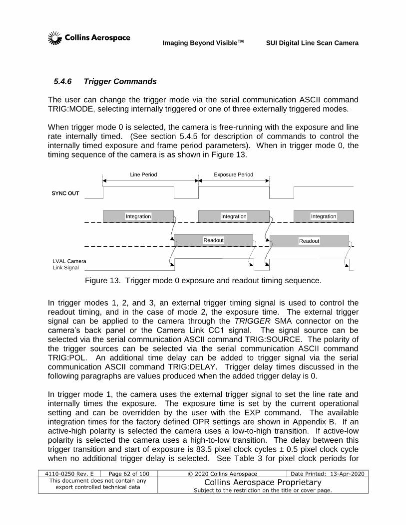
Imaging Beyond VisibleTM SUI Digital Line Scan Camera
4110-0250 Rev. E Page 62 of 100 © 2020 Collins Aerospace Date Printed: 13-Apr-2020
This document does not contain any export controlled technical data
Collins Aerospace Proprietary Subject to the restriction on the title or cover page.
5.4.6 Trigger Commands
The user can change the trigger mode via the serial communication ASCII command TRIG:MODE, selecting internally triggered or one of three externally triggered modes. When trigger mode 0 is selected, the camera is free-running with the exposure and line rate internally timed. (See section 5.4.5 for description of commands to control the internally timed exposure and frame period parameters). When in trigger mode 0, the timing sequence of the camera is as shown in Figure 13.
Integration Integration
Readout
SYNC OUT
Integration
Line Period Exposure Period
Integration Integration
Readout
SYNC OUT
Integration
LVAL Camera
Link Signal
Readout
Figure 13. Trigger mode 0 exposure and readout timing sequence.
In trigger modes 1, 2, and 3, an external trigger timing signal is used to control the readout timing, and in the case of mode 2, the exposure time. The external trigger signal can be applied to the camera through the TRIGGER SMA connector on the camera’s back panel or the Camera Link CC1 signal. The signal source can be selected via the serial communication ASCII command TRIG:SOURCE. The polarity of the trigger sources can be selected via the serial communication ASCII command TRIG:POL. An additional time delay can be added to trigger signal via the serial communication ASCII command TRIG:DELAY. Trigger delay times discussed in the following paragraphs are values produced when the added trigger delay is 0. In trigger mode 1, the camera uses the external trigger signal to set the line rate and internally times the exposure. The exposure time is set by the current operational setting and can be overridden by the user with the EXP command. The available integration times for the factory defined OPR settings are shown in Appendix B. If an active-high polarity is selected the camera uses a low-to-high transition. If active-low polarity is selected the camera uses a high-to-low transition. The delay between this trigger transition and start of exposure is 83.5 pixel clock cycles ± 0.5 pixel clock cycle when no additional trigger delay is selected. See Table 3 for pixel clock periods for
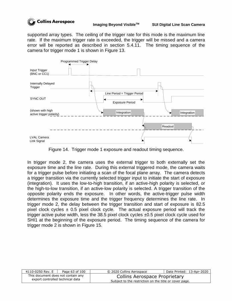
Imaging Beyond VisibleTM SUI Digital Line Scan Camera
4110-0250 Rev. E Page 63 of 100 © 2020 Collins Aerospace Date Printed: 13-Apr-2020
This document does not contain any export controlled technical data
Collins Aerospace Proprietary Subject to the restriction on the title or cover page.
supported array types. The ceiling of the trigger rate for this mode is the maximum line rate. If the maximum trigger rate is exceeded, the trigger will be missed and a camera error will be reported as described in section 5.4.11. The timing sequence of the camera for trigger mode 1 is shown in Figure 13.
Input Trigger
(BNC or CC1)
Internally Delayed
Trigger
Integration Integration
Readout
SYNC OUT
Line Period = Trigger Period
Programmed Trigger Delay
LVAL Camera
Link Signal
Exposure Period
(shown with high
active trigger polarity)
Figure 14. Trigger mode 1 exposure and readout timing sequence.
In trigger mode 2, the camera uses the external trigger to both externally set the exposure time and the line rate. During this external triggered mode, the camera waits for a trigger pulse before initiating a scan of the focal plane array. The camera detects a trigger transition via the currently selected trigger input to initiate the start of exposure (integration). It uses the low-to-high transition, if an active-high polarity is selected, or the high-to-low transition, if an active-low polarity is selected. A trigger transition of the opposite polarity ends the exposure. In other words, the active-trigger pulse width determines the exposure time and the trigger frequency determines the line rate. In trigger mode 2, the delay between the trigger transition and start of exposure is 82.5 pixel clock cycles ± 0.5 pixel clock cycle. The actual exposure period will track the trigger active pulse width, less the 38.5 pixel clock cycles ±0.5 pixel clock cycle used for SHI1 at the beginning of the exposure period. The timing sequence of the camera for trigger mode 2 is shown in Figure 15.
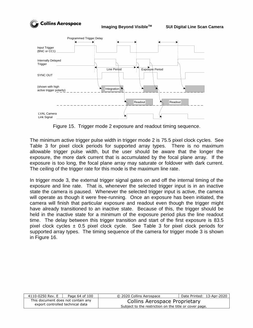
Imaging Beyond VisibleTM SUI Digital Line Scan Camera
4110-0250 Rev. E Page 64 of 100 © 2020 Collins Aerospace Date Printed: 13-Apr-2020
This document does not contain any export controlled technical data
Collins Aerospace Proprietary Subject to the restriction on the title or cover page.
Input Trigger
(BNC or CC1)
Internally Delayed
Trigger
Integration
Readout
SYNC OUT
Line Period
Programmed Trigger Delay
LVAL Camera
Link Signal
Exposure Period
(shown with high
active trigger polarity)
Readout
Figure 15. Trigger mode 2 exposure and readout timing sequence.
The minimum active trigger pulse width in trigger mode 2 is 75.5 pixel clock cycles. See Table 3 for pixel clock periods for supported array types. There is no maximum allowable trigger pulse width, but the user should be aware that the longer the exposure, the more dark current that is accumulated by the focal plane array. If the exposure is too long, the focal plane array may saturate or foldover with dark current. The ceiling of the trigger rate for this mode is the maximum line rate. In trigger mode 3, the external trigger signal gates on and off the internal timing of the exposure and line rate. That is, whenever the selected trigger input is in an inactive state the camera is paused. Whenever the selected trigger input is active, the camera will operate as though it were free-running. Once an exposure has been initiated, the camera will finish that particular exposure and readout even though the trigger might have already transitioned to an inactive state. Because of this, the trigger should be held in the inactive state for a minimum of the exposure period plus the line readout time. The delay between this trigger transition and start of the first exposure is 83.5 pixel clock cycles ± 0.5 pixel clock cycle. See Table 3 for pixel clock periods for supported array types. The timing sequence of the camera for trigger mode 3 is shown in Figure 16.
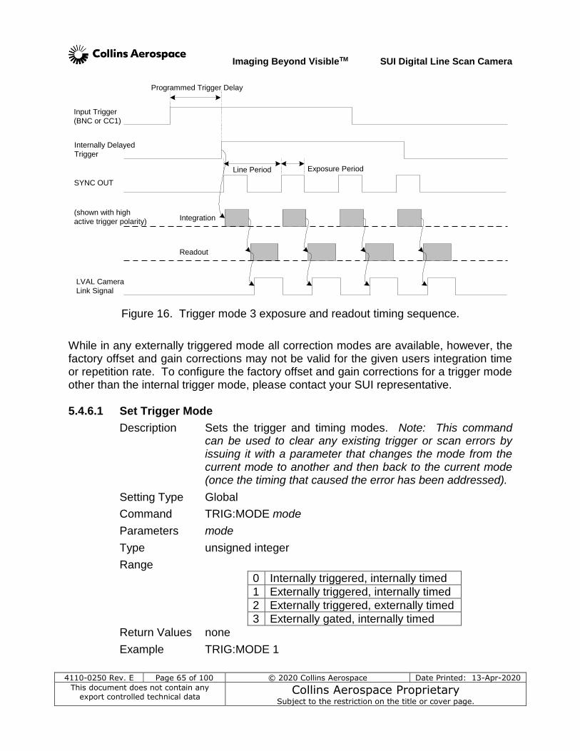
Imaging Beyond VisibleTM SUI Digital Line Scan Camera
4110-0250 Rev. E Page 65 of 100 © 2020 Collins Aerospace Date Printed: 13-Apr-2020
This document does not contain any export controlled technical data
Collins Aerospace Proprietary Subject to the restriction on the title or cover page.
Input Trigger
(BNC or CC1)
Internally Delayed
Trigger
SYNC OUT
Line Period
Programmed Trigger Delay
LVAL Camera
Link Signal
Exposure Period
(shown with high
active trigger polarity)Integration
Readout
Figure 16. Trigger mode 3 exposure and readout timing sequence.
While in any externally triggered mode all correction modes are available, however, the factory offset and gain corrections may not be valid for the given users integration time or repetition rate. To configure the factory offset and gain corrections for a trigger mode other than the internal trigger mode, please contact your SUI representative. 5.4.6.1 Set Trigger Mode
Description Sets the trigger and timing modes. Note: This command can be used to clear any existing trigger or scan errors by issuing it with a parameter that changes the mode from the current mode to another and then back to the current mode (once the timing that caused the error has been addressed).
Setting Type Global
Command TRIG:MODE mode
Parameters mode
Type unsigned integer
Range
0 Internally triggered, internally timed
1 Externally triggered, internally timed
2 Externally triggered, externally timed
3 Externally gated, internally timed
Return Values none
Example TRIG:MODE 1
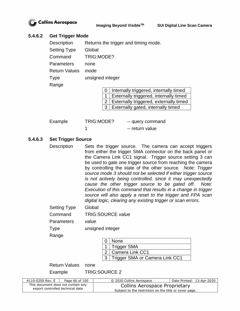
Imaging Beyond VisibleTM SUI Digital Line Scan Camera
4110-0250 Rev. E Page 66 of 100 © 2020 Collins Aerospace Date Printed: 13-Apr-2020
This document does not contain any export controlled technical data
Collins Aerospace Proprietary Subject to the restriction on the title or cover page.
5.4.6.2 Get Trigger Mode
Description Returns the trigger and timing mode.
Setting Type Global
Command TRIG:MODE?
Parameters none
Return Values mode
Type unsigned integer
Range
0 Internally triggered, internally timed
1 Externally triggered, internally timed
2 Externally triggered, externally timed
3 Externally gated, internally timed
Example TRIG:MODE? -- query command
1 -- return value 5.4.6.3 Set Trigger Source
Description Sets the trigger source. The camera can accept triggers from either the trigger SMA connector on the back panel or the Camera Link CC1 signal. Trigger source setting 3 can be used to gate one trigger source from reaching the camera by controlling the state of the other source. Note: Trigger source mode 3 should not be selected if either trigger source is not actively being controlled, since it may unexpectedly cause the other trigger source to be gated off. Note: Execution of this command that results in a change in trigger source will also apply a reset to the trigger and FPA scan digital logic, clearing any existing trigger or scan errors.
Setting Type Global
Command TRIG:SOURCE value
Parameters value
Type unsigned integer
Range
0 None
1 Trigger SMA
2 Camera Link CC1
3 Trigger SMA or Camera Link CC1
Return Values none
Example TRIG:SOURCE 2
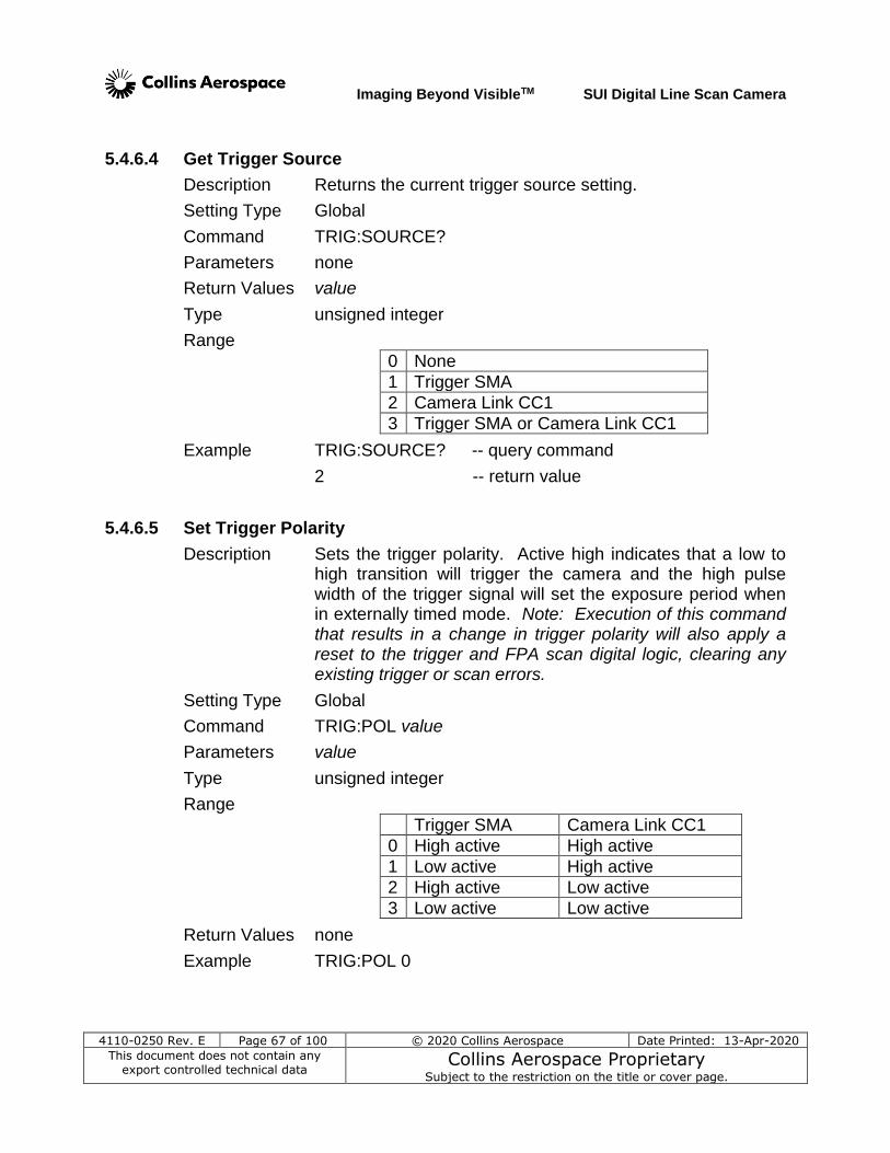
Imaging Beyond VisibleTM SUI Digital Line Scan Camera
4110-0250 Rev. E Page 67 of 100 © 2020 Collins Aerospace Date Printed: 13-Apr-2020
This document does not contain any export controlled technical data
Collins Aerospace Proprietary Subject to the restriction on the title or cover page.
5.4.6.4 Get Trigger Source
Description Returns the current trigger source setting.
Setting Type Global
Command TRIG:SOURCE?
Parameters none
Return Values value
Type unsigned integer
Range
0 None
1 Trigger SMA
2 Camera Link CC1
3 Trigger SMA or Camera Link CC1
Example TRIG:SOURCE? -- query command
2 -- return value
5.4.6.5 Set Trigger Polarity
Description Sets the trigger polarity. Active high indicates that a low to high transition will trigger the camera and the high pulse width of the trigger signal will set the exposure period when in externally timed mode. Note: Execution of this command that results in a change in trigger polarity will also apply a reset to the trigger and FPA scan digital logic, clearing any existing trigger or scan errors.
Setting Type Global
Command TRIG:POL value
Parameters value
Type unsigned integer
Range
Trigger SMA Camera Link CC1
0 High active High active
1 Low active High active
2 High active Low active
3 Low active Low active
Return Values none
Example TRIG:POL 0
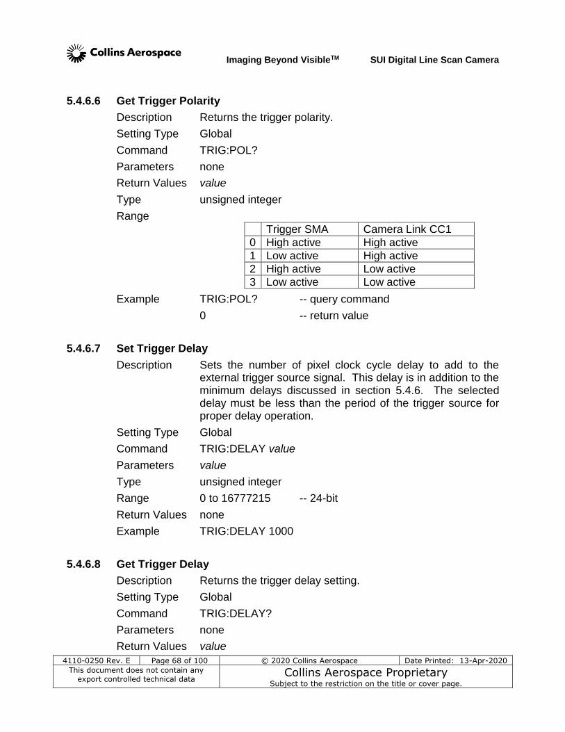
Imaging Beyond VisibleTM SUI Digital Line Scan Camera
4110-0250 Rev. E Page 68 of 100 © 2020 Collins Aerospace Date Printed: 13-Apr-2020
This document does not contain any export controlled technical data
Collins Aerospace Proprietary Subject to the restriction on the title or cover page.
5.4.6.6 Get Trigger Polarity
Description Returns the trigger polarity.
Setting Type Global
Command TRIG:POL?
Parameters none
Return Values value
Type unsigned integer
Range
Trigger SMA Camera Link CC1
0 High active High active
1 Low active High active
2 High active Low active
3 Low active Low active
Example TRIG:POL? -- query command
0 -- return value
5.4.6.7 Set Trigger Delay
Description Sets the number of pixel clock cycle delay to add to the external trigger source signal. This delay is in addition to the minimum delays discussed in section 5.4.6. The selected delay must be less than the period of the trigger source for proper delay operation.
Setting Type Global
Command TRIG:DELAY value
Parameters value
Type unsigned integer
Range 0 to 16777215 -- 24-bit
Return Values none
Example TRIG:DELAY 1000
5.4.6.8 Get Trigger Delay
Description Returns the trigger delay setting.
Setting Type Global
Command TRIG:DELAY?
Parameters none
Return Values value
Imaging Beyond VisibleTM SUI Digital Line Scan Camera
4110-0250 Rev. E Page 69 of 100 © 2020 Collins Aerospace Date Printed: 13-Apr-2020
This document does not contain any export controlled technical data
Collins Aerospace Proprietary Subject to the restriction on the title or cover page.
Type unsigned integer
Range 0 to 16777215 -- 24-bit
Example TRIG:DELAY? -- query command
1000 -- return value
5.4.7 Gain and Sensitivity Commands
The base sensitivity of the LDH2 and LDM cameras is primarily set by the choice of feedback capacitor in the pixel integration op amp illustrated in Figure 10. This is normally set by the user’s choice of operating mode (OPR) which also provides a range of exposure times appropriate for each capacitance setting offered in a specific camera model. The user may override the current OPR capacitor setting by use of the FPA:FBCAP command documented in this section, but must be aware that the stored non-uniformity corrections for offset and gain will not be appropriate for the alternate settings.
The cameras also provide a means to ‘amplify’ the post-acquisition digital signal for those cases where the signal is relatively small compared to the full bit range output by the camera. The GAIN:DIGITAL and GAIN:DIGITAL:MULT commands permit applying a gain multiplier to the data, by factors of 2 for the first command and by fractional values for the second. A fractional value can be useful for ensuring that corrected data for each pixel all saturate at the ADC limit simultaneously. For instance, the good linear pixels have non-uniformity limits of +/- 10% of the mean of the whole array. This implies that, for a non-uniformity corrected image, a strongly responding pixel might begin to saturate while the mean of the array is at 90%, and that a weakly responding pixel might not saturate until the mean has gone 10% above the ADC full scale. By choosing a GAIN:DIGITAL:MULT of 39 for an amplification of 39/32 or 1.22%, the same brightness level will cause all of the pixel values to reach the ADC limit simultaneously, avoiding imaging artifacts that might confuse users or analysis software.
With the high speed of the LDH2 camera requiring packing the Camera Link interface with two 12-bit pixels per clock transfer, this camera model must provide means for selecting which 12 of the ADC 14 bits are transmited to the host. The choices are to start the least-significant bit (LSB) of the 12-bit output with the LSB of the 14-bit data, the LSB+1 or the LSB+2. The latter case aligns the most-significant bit of the output with the ADC data MSB. For the LDH2 camera, the factory OPR settings control the bit alignment, choosing more significant bits when electronic noise dominates, or the the
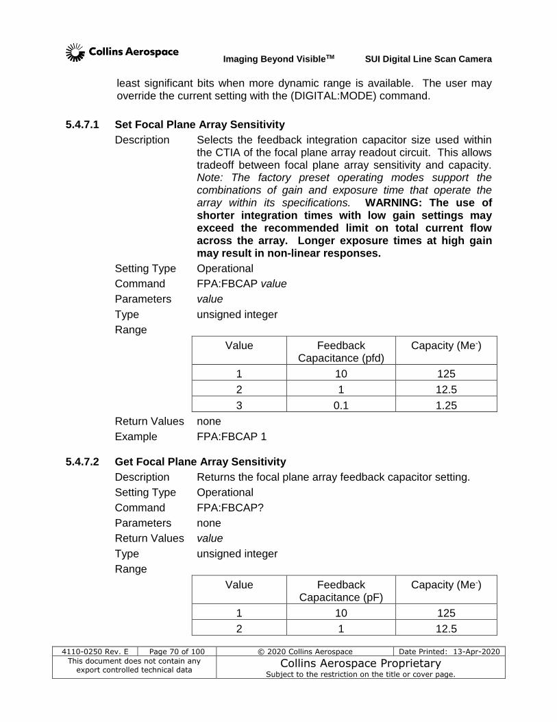
Imaging Beyond VisibleTM SUI Digital Line Scan Camera
4110-0250 Rev. E Page 70 of 100 © 2020 Collins Aerospace Date Printed: 13-Apr-2020
This document does not contain any export controlled technical data
Collins Aerospace Proprietary Subject to the restriction on the title or cover page.
least significant bits when more dynamic range is available. The user may override the current setting with the (DIGITAL:MODE) command.
5.4.7.1 Set Focal Plane Array Sensitivity
Description Selects the feedback integration capacitor size used within the CTIA of the focal plane array readout circuit. This allows tradeoff between focal plane array sensitivity and capacity. Note: The factory preset operating modes support the combinations of gain and exposure time that operate the array within its specifications. WARNING: The use of shorter integration times with low gain settings may exceed the recommended limit on total current flow across the array. Longer exposure times at high gain may result in non-linear responses.
Setting Type Operational
Command FPA:FBCAP value
Parameters value
Type unsigned integer
Range
Value Feedback Capacitance (pfd)
Capacity (Me-)
1 10 125
2 1 12.5
3 0.1 1.25
Return Values none
Example FPA:FBCAP 1
5.4.7.2 Get Focal Plane Array Sensitivity
Description Returns the focal plane array feedback capacitor setting.
Setting Type Operational
Command FPA:FBCAP?
Parameters none
Return Values value
Type unsigned integer
Range
Value Feedback Capacitance (pF)
Capacity (Me-)
1 10 125
2 1 12.5
Imaging Beyond VisibleTM SUI Digital Line Scan Camera
4110-0250 Rev. E Page 71 of 100 © 2020 Collins Aerospace Date Printed: 13-Apr-2020
This document does not contain any export controlled technical data
Collins Aerospace Proprietary Subject to the restriction on the title or cover page.
3 0.1 1.25
Example FPA:FBCAP? -- query command
1 -- return value
5.4.7.3 Set Digital Gain Description Sets the post-acquisition digital gain value. Digital gain can
be be used to stretch low signal images across a greater portion of the output range when the output is displayed on fixed scales. NOTE: Adjusting the digital gain amplifies noise and signal equally. Noise measurements should be done with 1X gain.
Setting Type Global
Command GAIN:DIGITAL value
Parameters value
Type string
Range Four settings as shown:
1X Apply 1X digital gain multiplier
2X Apply 2X digital gain multiplier
4X Apply 4X digital gain multiplier
8X Apply 8X digital gain multiplier
Return Values none
Example GAIN:DIGITAL 2X
5.4.7.4 Get Digital Gain
Description Returns the digital gain value
Setting Type Global
Command GAIN:DIGITAL?
Parameters none
Return Values value
Type string
Range Four settings as shown:
1X 1X digital gain multiplier applied
2X 2X digital gain multiplier applied
4X 4X digital gain multiplier applied
8X 8X digital gain multiplier applied
Example GAIN:DIGITAL? -- query command
2X -- return value
Imaging Beyond VisibleTM SUI Digital Line Scan Camera
4110-0250 Rev. E Page 72 of 100 © 2020 Collins Aerospace Date Printed: 13-Apr-2020
This document does not contain any export controlled technical data
Collins Aerospace Proprietary Subject to the restriction on the title or cover page.
5.4.7.5 Set Digital Gain Multiplier
Description Sets the digital gain multiplier value, providing a finer control than the base command. The actual digital gain applied is equal to this value divided by 32. Digital gain can be used to ensure that the pixel data fills the digital output range at the same intensity when offset and gain corrections are applied. In addition, digital gain can be used to stretch low signal images across a greater portion of the output range. NOTE: Adjusting the digital gain amplifies noise and signal equally. Noise measurements should be done with the MULT value of 32 which is equal to 1X gain
Setting Type Global
Command GAIN:DIGITAL:MULT value
Parameters value
Type unsigned integer
Range 1 to 256
Scale:
32 Is equivalent to 1X digital gain multiplier
64 Is equivalent to 2X digital gain multiplier
128 Is equivalent to 4X digital gain multiplier
256 Is equivalent to 8X digital gain multiplier
Return Values none
Example GAIN:DIGITAL:MULT 48 -- 1.5X gain 5.4.7.6 Get Digital Gain Multiplier
Description Returns the digital gain value
Setting Type Global
Command GAIN:DIGITAL:MULT?
Parameters none
Return Values value
Type unsigned integer
Range 1 to 256
Scale:
32 1X digital gain multiplier applied
64 2X digital gain multiplier applied
128 4X digital gain multiplier applied
256 8X digital gain multiplier applied
Example GAIN:DIGITAL:MULT? -- query command
48 -- return value -- 1.5X gain
Imaging Beyond VisibleTM SUI Digital Line Scan Camera
4110-0250 Rev. E Page 73 of 100 © 2020 Collins Aerospace Date Printed: 13-Apr-2020
This document does not contain any export controlled technical data
Collins Aerospace Proprietary Subject to the restriction on the title or cover page.
5.4.7.7 Set Camera Output Word Bit Alignment
Description For the LDH2 camera sets the alignment of the 12-bit Camera Link interface output with the 14-bit ADC data word. Note: User setting with this command will be overridden with the receipt of the next OPR command. Note: Not a valid command for use with the LDM; results in error response.
Setting Type Operational
Command DIGITAL:MODE value
Parameters value
Type unsigned integer
Range
Value Assignment
0 Not a valid argument for LDH2; triggers error
1 CAMERA LINK carries bits 13 to 2 of ADC
2 CAMERA LINKcarries bits 12 to 1 of ADC
3 CAMERA LINKcarries bits 11 to 0 of ADC
Return Values none
Example DIGITAL:MODE 1 -- set output to MSBs of ADC
5.4.7.8 Get Camera Output Word Bit Alignment
Description Returns the setting index indicating which 12-bits of the 14-bit ADC data word are active for transmitting over the Camera Link interface for the LDH2 model.
Setting Type Operational
Command DIGITAL:MODE?
Parameters none
Return Values value
Type unsigned integer
Range
Value Assignment
0 Value reported for LDM, not valid for LDH2
CAMERA LINK carries bits 13 to 0 of ADC
1 CAMERA LINK carries bits 13 to 2 of ADC
2 CAMERA LINK carries bits 12 to 1 of ADC
3 CAMERA LINK carries bits 11 to 0 of ADC
Imaging Beyond VisibleTM SUI Digital Line Scan Camera
4110-0250 Rev. E Page 74 of 100 © 2020 Collins Aerospace Date Printed: 13-Apr-2020
This document does not contain any export controlled technical data
Collins Aerospace Proprietary Subject to the restriction on the title or cover page.
Example DIGITAL:MODE? -- query command
1 -- return value
5.4.8 Imager Scanning Commands
5.4.8.1 Set Scan State
Description Sets the imager scanning state. When imager scanning is disabled no data will be available at the digital output port. Use this command to avoid timing errors when changing camera timing and triggering modes.
Setting Type Global
Command SCAN:STATE state
Parameters state
Type string
Range
ON Enable imager scanning
OFF Disable imager scanning
Return Values none
Example SCAN:STATE OFF
5.4.8.2 Get Scan State
Description Returns the state of the imager scanning.
Setting Type Global
Command SCAN:STATE?
Parameters none
Return Values state
Type string
Range
ON Imager scanning enabled
OFF Imager scanning disabled
Example SCAN:STATE? -- query command
ON -- return value
5.4.8.3 Set Over-Scan State
Description Sets the over-scan state. When over-scan is enabled the line valid signal width is increased to include inactive pixels before and after the active data. When over-scan is disabled line valid is the exact width of the active data, providing the
Imaging Beyond VisibleTM SUI Digital Line Scan Camera
4110-0250 Rev. E Page 75 of 100 © 2020 Collins Aerospace Date Printed: 13-Apr-2020
This document does not contain any export controlled technical data
Collins Aerospace Proprietary Subject to the restriction on the title or cover page.
frame grabber with more time between lines for buffer management. (See timing diagrams in section 3.1.2 for a detailed description of timing signals and over-scan data.)
Setting Type Global
Command SCAN:OVER state
Parameters state
Type string
Range
ON Enable over-scan
OFF Disable over-scan
Return Values none
Example SCAN:OVER OFF
5.4.8.4 Get Over-Scan State
Description Returns the over-scan state.
Setting Type Global
Command SCAN:OVER?
Parameters none
Return Values state
Type string
Range
ON Over-scan enabled
OFF Over-scan disabled
Example SCAN:OVER? -- query command
OFF -- return value
5.4.9 Thermal Commands 5.4.9.1 Get Camera Internal Temperature
Description Returns the internal camera nominal air temperature in degrees Celsius.
Setting Type N/A
Command CAMERA:TEMP?
Parameters none
Return Values temperature
Type signed integer
Range -55 to +125
Imaging Beyond VisibleTM SUI Digital Line Scan Camera
4110-0250 Rev. E Page 76 of 100 © 2020 Collins Aerospace Date Printed: 13-Apr-2020
This document does not contain any export controlled technical data
Collins Aerospace Proprietary Subject to the restriction on the title or cover page.
Example CAMERA:TEMP? -- query command
40 -- return value
5.4.9.2 Get Heat Sink Temperature
Description Returns the nominal heat sink temperature in degrees Celsius. This value is reported by a temperature measurement IC that has a thermal path to the hot side of the TEC. When values near the operating temperature range limits are reported through this command, the TEC may not be able to hold its locked status. Warning: The user should take active steps to ensure that the camera case temperature remains within the specified operating range.
Setting Type N/A
Command HS:TEMP?
Parameters none
Return Values temperature
Type decimal rounded to the nearest tenth degree
Range -20.0 to +70.0
Example HS:TEMP? -- query command
35.0 -- return value
5.4.9.3 Get Focal Plane Array Temperature
Description Returns the temperature of the focal plane array in degrees Celsius. When the status LED shows that the TEC is locked, the temperature matchs the TEC setpoint within 0.1 °C.
Setting Type N/A
Command FPA:TEMP?
Parameters none
Return Values temperature
Type decimal rounded to the nearest tenth degree
Range -20.0 to +80.0
Example FPA:TEMP? -- query command
25.0 -- return value
5.4.9.4 Get Thermoelectric Cooler Lock Status
Description Returns status of the thermoelectric cooler lock of the FPA temperature to the set point. The temperature is considered
Imaging Beyond VisibleTM SUI Digital Line Scan Camera
4110-0250 Rev. E Page 77 of 100 © 2020 Collins Aerospace Date Printed: 13-Apr-2020
This document does not contain any export controlled technical data
Collins Aerospace Proprietary Subject to the restriction on the title or cover page.
locked when the temperature is ±0.1°C of the set point. Typically this is within 1-2 minutes of power on. NOTE: The dark current and offset levels may take 10-15 minutes to reach equilibrium after power on.
Setting Type N/A
Command TEC:LOCK?
Parameters none
Return Values status
Type string
Range
LOCKED TEC stabilized
NOT LOCKED TEC not stabilized
Example TEC:LOCK? -- query command
LOCKED -- return value
5.4.10 Camera Information Commands
5.4.10.1 Get Camera Bit Depth
Description Returns the camera bit depth; 12 bits for the LDH2 model and 14 bits for the LDM version
Setting Type Factory Set
Command CAMERA:BITS?
Parameters none
Return Values value
Type Integer
Range Range
12 Bit depth of LDH2 camera
14 Bit depth of LDM camera
Example CAMERA:BITS? -- query command
12 -- return value
5.4.10.2 Get Camera Serial Number
Description Returns the camera serial number.
Setting Type Global
Command CAMERA:SN?
Imaging Beyond VisibleTM SUI Digital Line Scan Camera
4110-0250 Rev. E Page 78 of 100 © 2020 Collins Aerospace Date Printed: 13-Apr-2020
This document does not contain any export controlled technical data
Collins Aerospace Proprietary Subject to the restriction on the title or cover page.
Parameters none
Return Values value
Type string
Range up to 9 character alpha-numberic string
Example CAMERA:SN? -- query command
1027S8850 -- return value
5.4.10.3 Get Camera Part Number
Description Returns the camera part number. This will be useful to identify the camera configuration when asking for support from the factory.
Setting Type Global
Command CAMERA:PN?
Parameters none
Return Values value
Type string
Range up to 9 character alpha-numberic string
Example CAMERA:PN? -- query command
8000-0480 -- return value
5.4.10.4 Get Camera Revision
Description Returns the camera revision.
Setting Type Global
Command CAMERA:REV?
Parameters none
Return Values value
Type string
Range alpha-numeric string
Example CAMERA:REV? -- query command
(2) -- return value
5.4.10.5 Get Firmware Part Number
Description Returns the part number of the camera’s firmware.
Setting Type Global
Command FIRM:PN?
Imaging Beyond VisibleTM SUI Digital Line Scan Camera
4110-0250 Rev. E Page 79 of 100 © 2020 Collins Aerospace Date Printed: 13-Apr-2020
This document does not contain any export controlled technical data
Collins Aerospace Proprietary Subject to the restriction on the title or cover page.
Parameters none
Return Values value
Type string
Range 9 character alpha-numberic string
Example FIRM:PN? -- query command
4102-0106 -- return value
5.4.10.6 Get Firmware Revision
Description Returns the revision of the camera’s firmware.
Setting Type Global
Command FIRM:REV?
Parameters none
Return Values value
Type string
Range 1 or 2 character alpha-numeric string
Example FIRM:REV? -- query command
1 -- return value
5.4.10.7 Get Focal Plane Array Serial Number
Description Returns the serial number of the camera’s focal plane array.
Setting Type Global
Command FPA:SN?
Parameters none
Return Values value
Type string
Range up to 9 character alpha numeric string
Example FPA:SN? -- query command
4909S0836 -- return value
5.4.10.8 Get Focal Plane Array Number of Columns
Description Returns the number of columns of the focal plane array. For a linear array, it is the number of pixels.
Setting Type Global
Command FPA:COLS?
Parameters none
Imaging Beyond VisibleTM SUI Digital Line Scan Camera
4110-0250 Rev. E Page 80 of 100 © 2020 Collins Aerospace Date Printed: 13-Apr-2020
This document does not contain any export controlled technical data
Collins Aerospace Proprietary Subject to the restriction on the title or cover page.
Return Values value
Type unsigned integer
Range 0 to 65535
Example FPA:COLS? -- query command
1024 -- return value
5.4.10.9 Get Focal Plane Array Number of Rows
Description Returns the number of rows the array contains. For a linear array, the value is 1.
Setting Type Global
Command FPA:ROWS?
Parameters none
Return Values value
Type unsigned integer
Range 0 to 65535
Example FPA:ROWS? -- query command
1 -- return value
5.4.10.10 Get Focal Plane Array Number of ROICs
Description Returns the number of ROICs the array contains. For a LC linear array, the value is 1 for arrays with a 50 µm pitch or 2 for arrays with a 25 µm pitch.
Setting Type Global
Command FPA:ROICS?
Parameters none
Return Values value
Type unsigned integer
Range 1 or 2
Imaging Beyond VisibleTM SUI Digital Line Scan Camera
4110-0250 Rev. E Page 81 of 100 © 2020 Collins Aerospace Date Printed: 13-Apr-2020
This document does not contain any export controlled technical data
Collins Aerospace Proprietary Subject to the restriction on the title or cover page.
Example FPA:ROICS? -- query command
2 -- return value
5.4.11 Status and Reset Commands The user can poll the camera’s error status with the ERROR? command, which returns a binary encoded 8-bit error value. A non-zero error code indicates that an error has occurred. If the error code is not zero, the status LED will also flash as described in section 3.1.5. (Table 7 below can be used to decode the error value returned by the ERROR? command.) A bit value of one indicates an error. To reset an error bit the cause of the error must first be resolved. Once the error condition is resolved the error needs to be cleared. Most errors can be cleared by rebooting the camera. Some errors can be cleared by performing a firmware reset with the RESET command. Resolving the cause of the error alone will not clear the error.
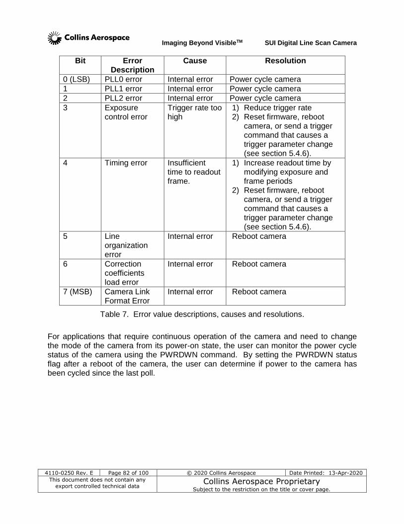
Imaging Beyond VisibleTM SUI Digital Line Scan Camera
4110-0250 Rev. E Page 82 of 100 © 2020 Collins Aerospace Date Printed: 13-Apr-2020
This document does not contain any export controlled technical data
Collins Aerospace Proprietary Subject to the restriction on the title or cover page.
Bit Error Description
Cause Resolution
0 (LSB) PLL0 error Internal error Power cycle camera
1 PLL1 error Internal error Power cycle camera
2 PLL2 error Internal error Power cycle camera
3 Exposure control error
Trigger rate too high
1) Reduce trigger rate 2) Reset firmware, reboot
camera, or send a trigger command that causes a trigger parameter change (see section 5.4.6).
4 Timing error Insufficient time to readout frame.
1) Increase readout time by modifying exposure and frame periods
2) Reset firmware, reboot camera, or send a trigger command that causes a trigger parameter change (see section 5.4.6).
5 Line organization error
Internal error Reboot camera
6 Correction coefficients load error
Internal error Reboot camera
7 (MSB) Camera Link Format Error
Internal error Reboot camera
Table 7. Error value descriptions, causes and resolutions.
For applications that require continuous operation of the camera and need to change the mode of the camera from its power-on state, the user can monitor the power cycle status of the camera using the PWRDWN command. By setting the PWRDWN status flag after a reboot of the camera, the user can determine if power to the camera has been cycled since the last poll.
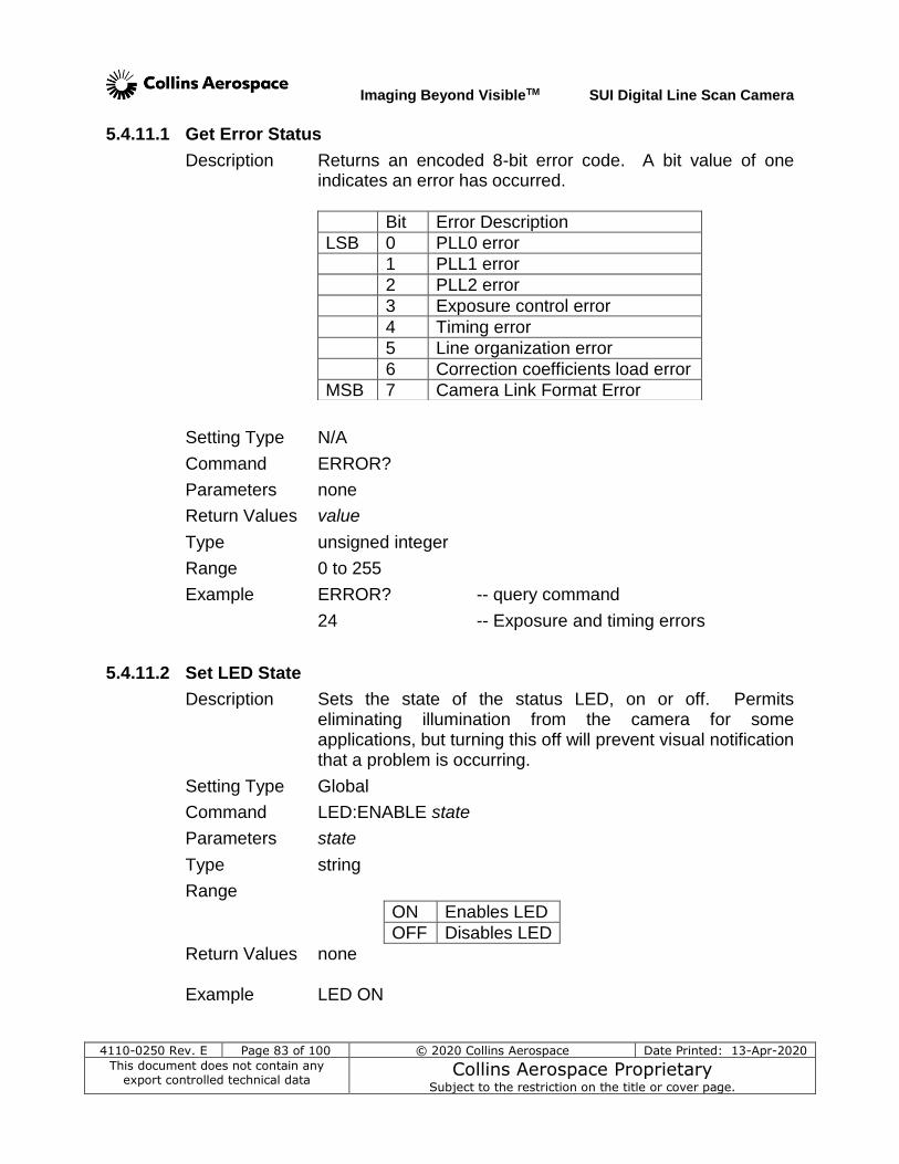
Imaging Beyond VisibleTM SUI Digital Line Scan Camera
4110-0250 Rev. E Page 83 of 100 © 2020 Collins Aerospace Date Printed: 13-Apr-2020
This document does not contain any export controlled technical data
Collins Aerospace Proprietary Subject to the restriction on the title or cover page.
5.4.11.1 Get Error Status
Description Returns an encoded 8-bit error code. A bit value of one indicates an error has occurred.
Setting Type N/A
Command ERROR?
Parameters none
Return Values value
Type unsigned integer
Range 0 to 255
Example ERROR? -- query command
24 -- Exposure and timing errors
5.4.11.2 Set LED State
Description Sets the state of the status LED, on or off. Permits eliminating illumination from the camera for some applications, but turning this off will prevent visual notification that a problem is occurring.
Setting Type Global
Command LED:ENABLE state
Parameters state
Type string
Range
ON Enables LED
OFF Disables LED
Return Values none Example LED ON
Bit Error Description
LSB 0 PLL0 error
1 PLL1 error
2 PLL2 error
3 Exposure control error
4 Timing error
5 Line organization error
6 Correction coefficients load error
MSB 7 Camera Link Format Error
Imaging Beyond VisibleTM SUI Digital Line Scan Camera
4110-0250 Rev. E Page 84 of 100 © 2020 Collins Aerospace Date Printed: 13-Apr-2020
This document does not contain any export controlled technical data
Collins Aerospace Proprietary Subject to the restriction on the title or cover page.
5.4.11.3 Get LED State
Description Returns the state of the status LED, on or off.
Setting Type Global
Command LED:ENABLE?
Return Values state
Type string
Range
ON Enables LED
OFF Disables LED
Example LED:ENABLE? -- query command
ON -- return state
5.4.11.4 Reset Firmware
Description Re-initializes the digital logic state. When the digital logic is placed in reset, camera operations will be suspended and all errors will be cleared. After a short time the firmware is taken out of reset the camera will resume operation. The primary function of this command is to reset the errors listed in Table 7 after the cause has been remedied.
Setting Type N/A
Command RESET
Parameters none
Return Values none Example RESET
5.4.11.5 Reboot Camera
Description Execute the power-up initialization sequence of the command processor
Setting Type N/A
Command REBOOT
Parameters none
Return Values banner
Type string
Range see section 5.3 for example banner output
Example REBOOT -- restart command processor
Imaging Beyond VisibleTM SUI Digital Line Scan Camera
4110-0250 Rev. E Page 85 of 100 © 2020 Collins Aerospace Date Printed: 13-Apr-2020
This document does not contain any export controlled technical data
Collins Aerospace Proprietary Subject to the restriction on the title or cover page.
5.4.11.6 Set Power-Down Detect Flag
Description Sets the power-down detect flag to the value 1. On reboot, this flag is initialized to 0. If the value is set using this command, the user can query its status to detect if the camera has been power cycled since the last query.
Setting Type N/A
Command PWRDWN
Parameters none
Return Values none
Example PWRDWN -- set power-down detect flag
5.4.11.7 Get Power-Down Detect Flag
Description Returns the power-down detect flag status.
Setting Type N/A
Command PWRDWN?
Parameters none
Return Values value
Type unsigned integer
Range
0 Initial value on reboot
1 Value set if user issues PWRDWN command to monitor power-down status
Example PWRDWN? -- query command
0 -- camera not power cycled
5.4.11.8 Get Elapsed Time Meter (day format)
Description Returns the number of days, hours, minutes and seconds since power-on, or since receipt of a previous REBOOT command.
Setting Type N/A
Command ETM?
Parameters none
Return Values time value
Type text in format “Days: d hh:mm:ss”
Range 0 to 49710 days -- 32-bit
Example ETM? -- query command
Days:2 01:01:01 -- accumulated seconds on
Imaging Beyond VisibleTM SUI Digital Line Scan Camera
4110-0250 Rev. E Page 86 of 100 © 2020 Collins Aerospace Date Printed: 13-Apr-2020
This document does not contain any export controlled technical data
Collins Aerospace Proprietary Subject to the restriction on the title or cover page.
5.4.11.9 Get Elapased Time Meter (in seconds)
Description Returns the number of seconds since power-on, or since receipt of a previous REBOOT command.
Setting Type N/A
Command ETM? ON
Parameters state
Return Values time value
Type integer
Range 0 to 4294967295 -- 32-bit counter
Example ETM? ON -- query command
272458 -- accumulated seconds on
5.4.11.10 Set Application Timer
Description Starts or stops the application clock timer. This clock counts time from the receipt of the ON command, reporting in steps of 0.001 seconds. This provides more resolution than the ETM command and the versatility of a separate timer for monitoring execution times of program steps without effecting the elapsed time counter. The maximum time is the equivalent of 49 days.
Setting Type Global
Command AP:TIMER state
Type string
Range
ON Resets and starts application timer
OFF Disables application timer
Return Values none
Example AP:TIMER ON -- reset seconds counter to
0.000
5.4.11.11 Get Application Timer
Description Returns the number of seconds since the AP:TIMER ON command was received, to 1/1000 second.
Setting Type N/A
Command AP:TIMER?
Parameters none
Return Values value
Imaging Beyond VisibleTM SUI Digital Line Scan Camera
4110-0250 Rev. E Page 87 of 100 © 2020 Collins Aerospace Date Printed: 13-Apr-2020
This document does not contain any export controlled technical data
Collins Aerospace Proprietary Subject to the restriction on the title or cover page.
Type decimal rounded to the nearest millisecond
Range 0.0 to 4294967.295 -- 32 bit / 1000
Example AP:TIMER -- query command
127.243 -- accumulated seconds since
counter started
5.4.12 Test Commands The Test Pattern mode can be used to verify the integrity of the data collection by the frame grabber. When this mode is enabled, the SUI LDH2 and LDM cameras return ramping pixel count values in place of digitized focal plane array data. The pixel values increment by 1 for successive pixels within a line and by 16 for each successive line. When a test pattern count reaches its maximum 14 bit depth value of 16,383, the next value returned rolls over to 0. The timing of the data presenting on the Camera Link
interface remains unchanged from when active pixel data is returned. The test pattern data is returned for both inactive, if their return has been enabled, and active pixels clock cycles of the data transfer shown in Figure 2. For the 14-bit LDM camera, these values are reported directly. For example, a test pattern line of data from a LDM camera with a 1,024 element linear array will start on a line that begins with the pixel value of 0 and end with a pixel value of 1023. The next line of the test pattern will then begin with 16 and end with 1039. By collecting 1024 successive lines into a buffer and displaying the result as a 1024 x 1024 image, a gradient fixed pattern of black through grey to white will be seen. If any other frame height is used, the gradient will roll through the display, drifting up when more lines are in the image height, or drifting down if fewer than 1024 lines are used. Since the LDH2 camera output is limited to 12-bits, only a subset of the test pattern intensities will be displayed. Each of the camera operating modes sets the digital mode to select the most appropriate 12 bits for the best dynamic range depending on which gain capacitor is in use. However, this means that the test pattern image displayed and digital data transmitted will be different depending on which OPR is active. Therefore, to get consistent results, the user of the TESTPAT ON command may want to also use the DIGITAL:MODE 1 command to select the 12 most significant bits (MSB) of the 14 bits to be sent over the Camera Link interface. With this selection active, the values mentioned above in the example for the 14-bit LDM camera will be divided by 4. Thus, the values on one line will ramp from 0 to 255 in intensity steps of 4 and the intensity will reach a maximum of 4095 before returning to 0. When the frame stamp mode is enabled, the LDM camera returns a count value that is incremented by 1 for each successive line in the first pixel of the line shown in Figure 2. When the stamp count reaches its maximum 14-bit depth value of 16,383, the next value returned rolls over to 0. The frame stamp mode can be used to verify the continuity of data collection by the frame grabber. For the 12-bit LDH2, the values
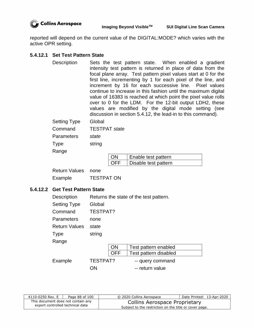
Imaging Beyond VisibleTM SUI Digital Line Scan Camera
4110-0250 Rev. E Page 88 of 100 © 2020 Collins Aerospace Date Printed: 13-Apr-2020
This document does not contain any export controlled technical data
Collins Aerospace Proprietary Subject to the restriction on the title or cover page.
reported will depend on the current value of the DIGITAL:MODE? which varies with the active OPR setting. 5.4.12.1 Set Test Pattern State
Description Sets the test pattern state. When enabled a gradient intensity test pattern is returned in place of data from the focal plane array. Test pattern pixel values start at 0 for the first line, incrementing by 1 for each pixel of the line, and increment by 16 for each successive line. Pixel values continue to increase in this fashion until the maximum digital value of 16383 is reached at which point the pixel value rolls over to 0 for the LDM. For the 12-bit output LDH2, these values are modified by the digital mode setting (see discussion in section 5.4.12, the lead-in to this command).
Setting Type Global
Command TESTPAT state
Parameters state
Type string
Range
ON Enable test pattern
OFF Disable test pattern
Return Values none
Example TESTPAT ON
5.4.12.2 Get Test Pattern State
Description Returns the state of the test pattern.
Setting Type Global
Command TESTPAT?
Parameters none
Return Values state
Type string
Range
ON Test pattern enabled
OFF Test pattern disabled
Example TESTPAT? -- query command
ON -- return value
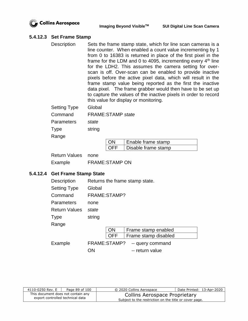
Imaging Beyond VisibleTM SUI Digital Line Scan Camera
4110-0250 Rev. E Page 89 of 100 © 2020 Collins Aerospace Date Printed: 13-Apr-2020
This document does not contain any export controlled technical data
Collins Aerospace Proprietary Subject to the restriction on the title or cover page.
5.4.12.3 Set Frame Stamp
Description Sets the frame stamp state, which for line scan cameras is a line counter. When enabled a count value incrementing by 1 from 0 to 16383 is returned in place of the first pixel in the frame for the LDM and 0 to 4095, incrementing every 4th line for the LDH2. This assumes the camera setting for over-scan is off. Over-scan can be enabled to provide inactive pixels before the active pixel data, which will result in the frame stamp value being reported as the first the inactive data pixel. The frame grabber would then have to be set up to capture the values of the inactive pixels in order to record this value for display or monitoring.
Setting Type Global
Command FRAME:STAMP state
Parameters state
Type string
Range
ON Enable frame stamp
OFF Disable frame stamp
Return Values none
Example FRAME:STAMP ON
5.4.12.4 Get Frame Stamp State
Description Returns the frame stamp state.
Setting Type Global
Command FRAME:STAMP?
Parameters none
Return Values state
Type string
Range
ON Frame stamp enabled
OFF Frame stamp disabled
Example FRAME:STAMP? -- query command
ON -- return value
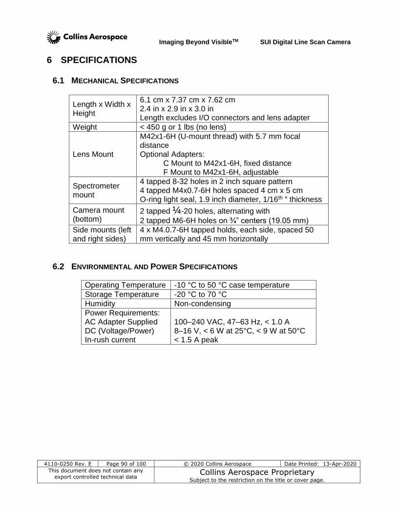
Imaging Beyond VisibleTM SUI Digital Line Scan Camera
4110-0250 Rev. E Page 90 of 100 © 2020 Collins Aerospace Date Printed: 13-Apr-2020
This document does not contain any export controlled technical data
Collins Aerospace Proprietary Subject to the restriction on the title or cover page.
6 SPECIFICATIONS
6.1 MECHANICAL SPECIFICATIONS
Length x Width x Height
6.1 cm x 7.37 cm x 7.62 cm 2.4 in x 2.9 in x 3.0 in Length excludes I/O connectors and lens adapter
Weight < 450 g or 1 lbs (no lens)
Lens Mount
M42x1-6H (U-mount thread) with 5.7 mm focal distance Optional Adapters: C Mount to M42x1-6H, fixed distance F Mount to M42x1-6H, adjustable
Spectrometer mount
4 tapped 8-32 holes in 2 inch square pattern 4 tapped M4x0.7-6H holes spaced 4 cm x 5 cm O-ring light seal, 1.9 inch diameter, 1/16th “ thickness
Camera mount (bottom)
2 tapped ¼-20 holes, alternating with
2 tapped M6-6H holes on ¾” centers (19.05 mm)
Side mounts (left and right sides)
4 x M4.0.7-6H tapped holds, each side, spaced 50 mm vertically and 45 mm horizontally
6.2 ENVIRONMENTAL AND POWER SPECIFICATIONS
Operating Temperature -10 °C to 50 °C case temperature
Storage Temperature -20 °C to 70 °C
Humidity Non-condensing
Power Requirements: AC Adapter Supplied DC (Voltage/Power) In-rush current
100–240 VAC, 47–63 Hz, < 1.0 A 8–16 V, < 6 W at 25°C, < 9 W at 50°C < 1.5 A peak
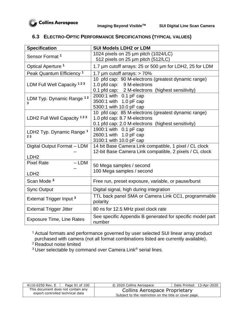
Imaging Beyond VisibleTM SUI Digital Line Scan Camera
4110-0250 Rev. E Page 91 of 100 © 2020 Collins Aerospace Date Printed: 13-Apr-2020
This document does not contain any export controlled technical data
Collins Aerospace Proprietary Subject to the restriction on the title or cover page.
6.3 ELECTRO-OPTIC PERFORMANCE SPECIFICATIONS (TYPICAL VALUES)
Specification SUI Models LDH2 or LDM
Sensor Format 1 1024 pixels on 25 µm pitch (1024/LC) 512 pixels on 25 µm pitch (512/LC)
Optical Aperture 1 1.7 µm cutoff arrays: 25 or 500 µm for LDH2, 25 for LDM
Peak Quantum Efficiency 1 1.7 µm cutoff arrays: > 70%
LDM Full Well Capacity 1 2 3 10 pfd cap: 90 M-electrons (greatest dynamic range) 1.0 pfd cap: 9 M-electrons 0.1 pfd cap: 2 M-electrons (highest sensitivity)
LDM Typ. Dynamic Range 1 2
3
2000:1 with 0.1 pF cap 3500:1 with 1.0 pF cap 5300:1 with 10.0 pF cap
LDH2 Full Well Capacity 1 2 3 10 pfd cap: 85 M-electrons (greatest dynamic range) 1.0 pfd cap: 8.7 M-electrons 0.1 pfd cap: 2.0 M-electrons (highest sensitivity)
LDH2 Typ. Dynamic Range 1
2 3
1900:1 with 0.1 pF cap 2600:1 with 1.0 pF cap 3100:1 with 10.0 pF cap
Digital Output Format – LDM – LDH2
14 bit Base Camera Link compatible, 1 pixel / CL clock 12-bit Base Camera Link compatible, 2 pixels / CL clock
Pixel Rate – LDM – LDH2
50 Mega samples / second 100 Mega samples / second
Scan Mode 3 Free run, preset exposure, variable, or pause/burst
Sync Output Digital signal, high during integration
External Trigger Input 3 TTL back panel SMA or Camera Link CC1, programmable polarity
External Trigger Jitter 80 ns for 12.5 MHz pixel clock rate
Exposure Time, Line Rates See specific Appendix B generated for specific model part number
1 Actual formats and performance governed by user selected SUI linear array product purchased with camera (not all format combinations listed are currently available).
2 Readout noise limited 3 User selectable by command over Camera Link® serial lines.
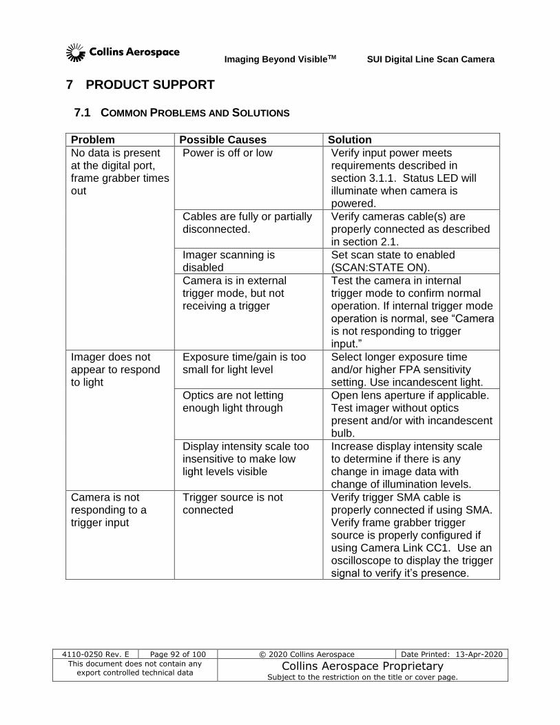
Imaging Beyond VisibleTM SUI Digital Line Scan Camera
4110-0250 Rev. E Page 92 of 100 © 2020 Collins Aerospace Date Printed: 13-Apr-2020
This document does not contain any export controlled technical data
Collins Aerospace Proprietary Subject to the restriction on the title or cover page.
7 PRODUCT SUPPORT
7.1 COMMON PROBLEMS AND SOLUTIONS Problem Possible Causes Solution
No data is present at the digital port, frame grabber times out
Power is off or low Verify input power meets requirements described in section 3.1.1. Status LED will illuminate when camera is powered.
Cables are fully or partially disconnected.
Verify cameras cable(s) are properly connected as described in section 2.1.
Imager scanning is disabled
Set scan state to enabled (SCAN:STATE ON).
Camera is in external trigger mode, but not receiving a trigger
Test the camera in internal trigger mode to confirm normal operation. If internal trigger mode operation is normal, see “Camera is not responding to trigger input.”
Imager does not appear to respond to light
Exposure time/gain is too small for light level
Select longer exposure time and/or higher FPA sensitivity setting. Use incandescent light.
Optics are not letting enough light through
Open lens aperture if applicable. Test imager without optics present and/or with incandescent bulb.
Display intensity scale too insensitive to make low light levels visible
Increase display intensity scale to determine if there is any change in image data with change of illumination levels.
Camera is not responding to a trigger input
Trigger source is not connected
Verify trigger SMA cable is properly connected if using SMA. Verify frame grabber trigger source is properly configured if using Camera Link CC1. Use an oscilloscope to display the trigger signal to verify it’s presence.
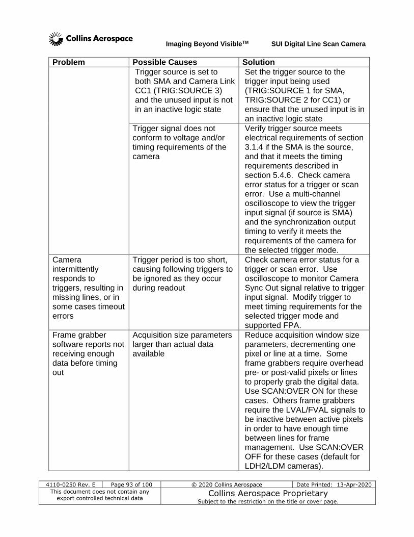
Imaging Beyond VisibleTM SUI Digital Line Scan Camera
4110-0250 Rev. E Page 93 of 100 © 2020 Collins Aerospace Date Printed: 13-Apr-2020
This document does not contain any export controlled technical data
Collins Aerospace Proprietary Subject to the restriction on the title or cover page.
Problem Possible Causes Solution
Trigger source is set to both SMA and Camera Link CC1 (TRIG:SOURCE 3) and the unused input is not in an inactive logic state
Set the trigger source to the trigger input being used (TRIG:SOURCE 1 for SMA, TRIG:SOURCE 2 for CC1) or ensure that the unused input is in an inactive logic state
Trigger signal does not conform to voltage and/or timing requirements of the camera
Verify trigger source meets electrical requirements of section 3.1.4 if the SMA is the source, and that it meets the timing requirements described in section 5.4.6. Check camera error status for a trigger or scan error. Use a multi-channel oscilloscope to view the trigger input signal (if source is SMA) and the synchronization output timing to verify it meets the requirements of the camera for the selected trigger mode.
Camera intermittently responds to triggers, resulting in missing lines, or in some cases timeout errors
Trigger period is too short, causing following triggers to be ignored as they occur during readout
Check camera error status for a trigger or scan error. Use oscilloscope to monitor Camera Sync Out signal relative to trigger input signal. Modify trigger to meet timing requirements for the selected trigger mode and supported FPA.
Frame grabber software reports not receiving enough data before timing out
Acquisition size parameters larger than actual data available
Reduce acquisition window size parameters, decrementing one pixel or line at a time. Some frame grabbers require overhead pre- or post-valid pixels or lines to properly grab the digital data. Use SCAN:OVER ON for these cases. Others frame grabbers require the LVAL/FVAL signals to be inactive between active pixels in order to have enough time between lines for frame management. Use SCAN:OVER OFF for these cases (default for LDH2/LDM cameras).
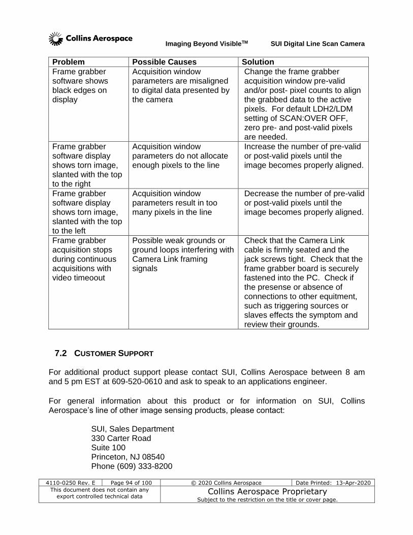
Imaging Beyond VisibleTM SUI Digital Line Scan Camera
4110-0250 Rev. E Page 94 of 100 © 2020 Collins Aerospace Date Printed: 13-Apr-2020
This document does not contain any export controlled technical data
Collins Aerospace Proprietary Subject to the restriction on the title or cover page.
Problem Possible Causes Solution
Frame grabber software shows black edges on display
Acquisition window parameters are misaligned to digital data presented by the camera
Change the frame grabber acquisition window pre-valid and/or post- pixel counts to align the grabbed data to the active pixels. For default LDH2/LDM setting of SCAN:OVER OFF, zero pre- and post-valid pixels are needed.
Frame grabber software display shows torn image, slanted with the top to the right
Acquisition window parameters do not allocate enough pixels to the line
Increase the number of pre-valid or post-valid pixels until the image becomes properly aligned.
Frame grabber software display shows torn image, slanted with the top to the left
Acquisition window parameters result in too many pixels in the line
Decrease the number of pre-valid or post-valid pixels until the image becomes properly aligned.
Frame grabber acquisition stops during continuous acquisitions with video timeoout
Possible weak grounds or ground loops interfering with Camera Link framing signals
Check that the Camera Link cable is firmly seated and the jack screws tight. Check that the frame grabber board is securely fastened into the PC. Check if the presense or absence of connections to other equitment, such as triggering sources or slaves effects the symptom and review their grounds.
7.2 CUSTOMER SUPPORT For additional product support please contact SUI, Collins Aerospace between 8 am and 5 pm EST at 609-520-0610 and ask to speak to an applications engineer.
For general information about this product or for information on SUI, Collins Aerospace’s line of other image sensing products, please contact:
SUI, Sales Department 330 Carter Road Suite 100 Princeton, NJ 08540 Phone (609) 333-8200

Imaging Beyond VisibleTM SUI Digital Line Scan Camera
4110-0250 Rev. E Page 95 of 100 © 2020 Collins Aerospace Date Printed: 13-Apr-2020
This document does not contain any export controlled technical data
Collins Aerospace Proprietary Subject to the restriction on the title or cover page.
http://www.sensorsinc.com/customersupport.html
7.3 WARRANTY All SUI, Collins Aerospace products are warranted to be free from defects in workmanship and materials “Nonconformity” for a period of 12 months from the date of shipment. This warranty is limited to the repair or replacement of the unit. This warranty does not apply to products which SUI, Collins Aerospace determines, upon inspection, have failed, become defective or unworkable due to abuse, mishandling, misuse, alteration, negligence, improper installation, use which is not in accordance with the information and precautions described in the applicable operating manual, or other causes beyond SUI, Collins Aerospace’s control. This warranty does not apply to (i) any products or components not manufactured by SUI, Collins Aerospace or (ii) any aspect of the products based on Buyer’s specification, unless Seller has reviewed and approved such specification in writing. In-warranty repaired or replacement products are warranted only for the remaining non-expired portion of the original warranty period. Except for the foregoing warranty, SUI, Collins Aerospace specifically disclaims and excludes all other warranties, expressed or implied, including implied warranties of non-infringement, merchantability or fitness for a particular purpose. If visible damage has occurred: It must be noted on all copies of the freight bill and signed by the driver. This preserves your rights and the carrier’s liability. If damage was concealed: Open all cartons as soon as possible! Concealed damage must be reported in writing within 5 days of receipt. Contact our shipping department for assistance between 8:00 A.M. and 5:00 P.M. EST All product returns require contacting the factory to request a Return Material Authorization number (RMA). End users reporting a problem should be prepared to supply the product model number, serial number, description of the problem, and relevant information about the instrumental setup, environmental conditions, user history, etc, as well as contact information. When returning a camera, all accessories, power supplies, cables and camera case should be included to ensure the user problem can be duplicated and corrected.
Imaging Beyond VisibleTM SUI Digital Line Scan Camera
4110-0250 Rev. E Page 96 of 100 © 2020 Collins Aerospace Date Printed: 13-Apr-2020
This document does not contain any export controlled technical data
Collins Aerospace Proprietary Subject to the restriction on the title or cover page.
8 LIST OF ABBREVIATIONS
AC: Alternating Current (i.e. wall power / mains voltage)
ADC: analog-to-digital converter
ASCII: American standard code for information interchange
BNC: Bayonet Neill Concelman (standard lab / radio frequency coaxial cable connector)
CCTV: closed-circuit television
CD: Compact Disc
CDS: Correlated Double Sampling
CMOS: Complementary Metal Oxide Semiconductor (silicon chip circuitry type)
CTIA: capacitive transimpedance amplifier
DC: Direct Current (i.e. Battery supply voltage)
EST: eastern standard time
FPA: focal plane array
IMAQ: Image Acquisition (National Instruments’ frame grabber driver software)
InGaAs: indium gallium arsenide
ITAR: International Traffic in Arms Regulations
INT: Integration time (from timing chart)
LC: Linear array, MUX version C series
LDH: Linescan, Digital, High Speed; LDH2 is a 2nd generation version
LDM: Linescan, Digital, Machine Vision; uses the LDH2 platform
LDV: Linescan, Digital Video
LED: light-emitting diode
LSB: Least-significant bit
LVDS: low voltage differential signaling
MDR: Mini Delta Ribbon cable connector – full size Camera Link connector
MSB: Most-significant bit
MUX: Multiplexer
NI : National Instruments
NIR : near infrared
PCI: peripheral component interconnect
Imaging Beyond VisibleTM SUI Digital Line Scan Camera
4110-0250 Rev. E Page 97 of 100 © 2020 Collins Aerospace Date Printed: 13-Apr-2020
This document does not contain any export controlled technical data
Collins Aerospace Proprietary Subject to the restriction on the title or cover page.
QE: quantum efficiency
RMA: return material authorization
ROI: region of interest
SAE: Society of Automotive Engineers
SDR: Shrunk Delta Ribbon Camera Link mini-connector
SHI: Sample and Hold Integrator, from timing discussion (SHI1 and SHI2 are pre and post integration, respectively)
SLR: single lens reflex
SMA: Sub-Miniature A connector
SUI: Sensors Unlimited Inc. – a COLLINS AEROSPACE Company
SWIR: shortwave infrared
TEC: thermoelectric cooler
TTL: transistor-transistor logic (digital signaling standard)

Imaging Beyond VisibleTM SUI Digital Line Scan Camera
4110-0250 Rev. E Page 98 of 100 © 2020 Collins Aerospace Date Printed: 13-Apr-2020
This document does not contain any export controlled technical data
Collins Aerospace Proprietary Subject to the restriction on the title or cover page.
9 NOTES ______________________________________________________________________
______________________________________________________________________
______________________________________________________________________
______________________________________________________________________
______________________________________________________________________
______________________________________________________________________
______________________________________________________________________
______________________________________________________________________
______________________________________________________________________
______________________________________________________________________
______________________________________________________________________
______________________________________________________________________
______________________________________________________________________
______________________________________________________________________
______________________________________________________________________
______________________________________________________________________
______________________________________________________________________
______________________________________________________________________
______________________________________________________________________
______________________________________________________________________
______________________________________________________________________
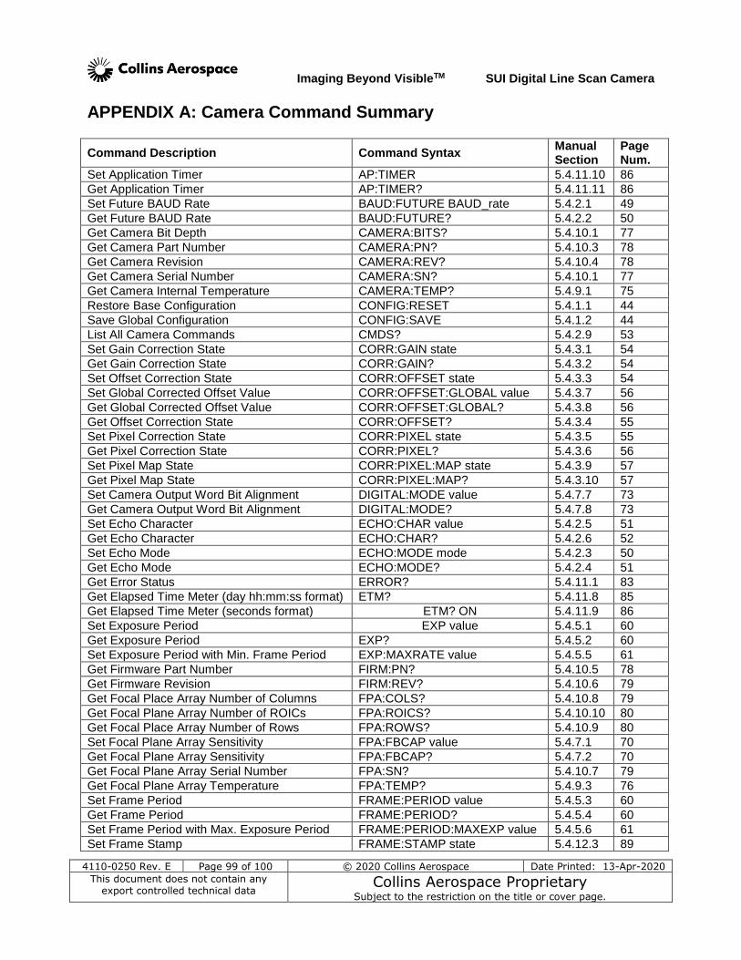
Imaging Beyond VisibleTM SUI Digital Line Scan Camera
4110-0250 Rev. E Page 99 of 100 © 2020 Collins Aerospace Date Printed: 13-Apr-2020
This document does not contain any export controlled technical data
Collins Aerospace Proprietary Subject to the restriction on the title or cover page.
APPENDIX A: Camera Command Summary
Command Description Command Syntax Manual Section
Page Num.
Set Application Timer AP:TIMER 5.4.11.10 86
Get Application Timer AP:TIMER? 5.4.11.11 86
Set Future BAUD Rate BAUD:FUTURE BAUD_rate 5.4.2.1 49
Get Future BAUD Rate BAUD:FUTURE? 5.4.2.2 50
Get Camera Bit Depth CAMERA:BITS? 5.4.10.1 77
Get Camera Part Number CAMERA:PN? 5.4.10.3 78
Get Camera Revision CAMERA:REV? 5.4.10.4 78
Get Camera Serial Number CAMERA:SN? 5.4.10.1 77
Get Camera Internal Temperature CAMERA:TEMP? 5.4.9.1 75
Restore Base Configuration CONFIG:RESET 5.4.1.1 44
Save Global Configuration CONFIG:SAVE 5.4.1.2 44
List All Camera Commands CMDS? 5.4.2.9 53
Set Gain Correction State CORR:GAIN state 5.4.3.1 54
Get Gain Correction State CORR:GAIN? 5.4.3.2 54
Set Offset Correction State CORR:OFFSET state 5.4.3.3 54
Set Global Corrected Offset Value CORR:OFFSET:GLOBAL value 5.4.3.7 56
Get Global Corrected Offset Value CORR:OFFSET:GLOBAL? 5.4.3.8 56
Get Offset Correction State CORR:OFFSET? 5.4.3.4 55
Set Pixel Correction State CORR:PIXEL state 5.4.3.5 55
Get Pixel Correction State CORR:PIXEL? 5.4.3.6 56
Set Pixel Map State CORR:PIXEL:MAP state 5.4.3.9 57
Get Pixel Map State CORR:PIXEL:MAP? 5.4.3.10 57
Set Camera Output Word Bit Alignment DIGITAL:MODE value 5.4.7.7 73
Get Camera Output Word Bit Alignment DIGITAL:MODE? 5.4.7.8 73
Set Echo Character ECHO:CHAR value 5.4.2.5 51
Get Echo Character ECHO:CHAR? 5.4.2.6 52
Set Echo Mode ECHO:MODE mode 5.4.2.3 50
Get Echo Mode ECHO:MODE? 5.4.2.4 51
Get Error Status ERROR? 5.4.11.1 83
Get Elapsed Time Meter (day hh:mm:ss format) ETM? 5.4.11.8 85
Get Elapsed Time Meter (seconds format) ETM? ON 5.4.11.9 86
Set Exposure Period EXP value 5.4.5.1 60
Get Exposure Period EXP? 5.4.5.2 60
Set Exposure Period with Min. Frame Period EXP:MAXRATE value 5.4.5.5 61
Get Firmware Part Number FIRM:PN? 5.4.10.5 78
Get Firmware Revision FIRM:REV? 5.4.10.6 79
Get Focal Place Array Number of Columns FPA:COLS? 5.4.10.8 79
Get Focal Plane Array Number of ROICs FPA:ROICS? 5.4.10.10 80
Get Focal Place Array Number of Rows FPA:ROWS? 5.4.10.9 80
Set Focal Plane Array Sensitivity FPA:FBCAP value 5.4.7.1 70
Get Focal Plane Array Sensitivity FPA:FBCAP? 5.4.7.2 70
Get Focal Plane Array Serial Number FPA:SN? 5.4.10.7 79
Get Focal Plane Array Temperature FPA:TEMP? 5.4.9.3 76
Set Frame Period FRAME:PERIOD value 5.4.5.3 60
Get Frame Period FRAME:PERIOD? 5.4.5.4 60
Set Frame Period with Max. Exposure Period FRAME:PERIOD:MAXEXP value 5.4.5.6 61
Set Frame Stamp FRAME:STAMP state 5.4.12.3 89
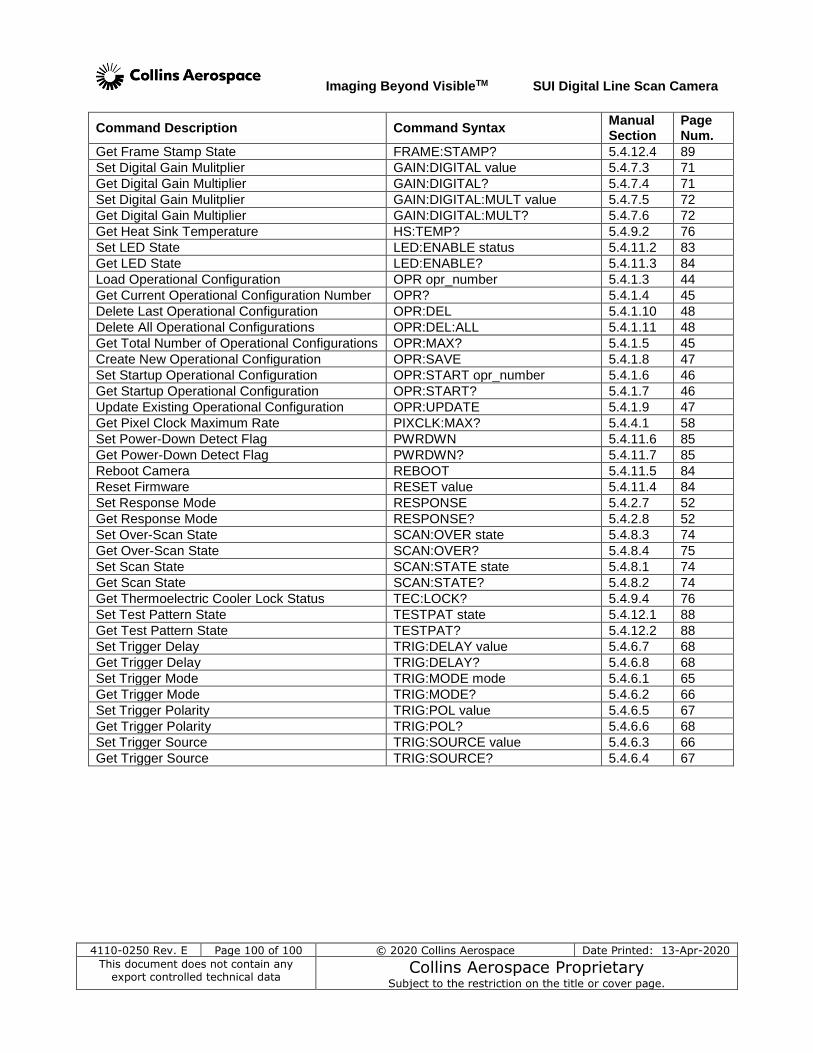
Imaging Beyond VisibleTM SUI Digital Line Scan Camera
4110-0250 Rev. E Page 100 of 100 © 2020 Collins Aerospace Date Printed: 13-Apr-2020
This document does not contain any export controlled technical data
Collins Aerospace Proprietary Subject to the restriction on the title or cover page.
Command Description Command Syntax Manual Section
Page Num.
Get Frame Stamp State FRAME:STAMP? 5.4.12.4 89
Set Digital Gain Mulitplier GAIN:DIGITAL value 5.4.7.3 71
Get Digital Gain Multiplier GAIN:DIGITAL? 5.4.7.4 71
Set Digital Gain Mulitplier GAIN:DIGITAL:MULT value 5.4.7.5 72
Get Digital Gain Multiplier GAIN:DIGITAL:MULT? 5.4.7.6 72
Get Heat Sink Temperature HS:TEMP? 5.4.9.2 76
Set LED State LED:ENABLE status 5.4.11.2 83
Get LED State LED:ENABLE? 5.4.11.3 84
Load Operational Configuration OPR opr_number 5.4.1.3 44
Get Current Operational Configuration Number OPR? 5.4.1.4 45
Delete Last Operational Configuration OPR:DEL 5.4.1.10 48
Delete All Operational Configurations OPR:DEL:ALL 5.4.1.11 48
Get Total Number of Operational Configurations OPR:MAX? 5.4.1.5 45
Create New Operational Configuration OPR:SAVE 5.4.1.8 47
Set Startup Operational Configuration OPR:START opr_number 5.4.1.6 46
Get Startup Operational Configuration OPR:START? 5.4.1.7 46
Update Existing Operational Configuration OPR:UPDATE 5.4.1.9 47
Get Pixel Clock Maximum Rate PIXCLK:MAX? 5.4.4.1 58
Set Power-Down Detect Flag PWRDWN 5.4.11.6 85
Get Power-Down Detect Flag PWRDWN? 5.4.11.7 85
Reboot Camera REBOOT 5.4.11.5 84
Reset Firmware RESET value 5.4.11.4 84
Set Response Mode RESPONSE 5.4.2.7 52
Get Response Mode RESPONSE? 5.4.2.8 52
Set Over-Scan State SCAN:OVER state 5.4.8.3 74
Get Over-Scan State SCAN:OVER? 5.4.8.4 75
Set Scan State SCAN:STATE state 5.4.8.1 74
Get Scan State SCAN:STATE? 5.4.8.2 74
Get Thermoelectric Cooler Lock Status TEC:LOCK? 5.4.9.4 76
Set Test Pattern State TESTPAT state 5.4.12.1 88
Get Test Pattern State TESTPAT? 5.4.12.2 88
Set Trigger Delay TRIG:DELAY value 5.4.6.7 68
Get Trigger Delay TRIG:DELAY? 5.4.6.8 68
Set Trigger Mode TRIG:MODE mode 5.4.6.1 65
Get Trigger Mode TRIG:MODE? 5.4.6.2 66
Set Trigger Polarity TRIG:POL value 5.4.6.5 67
Get Trigger Polarity TRIG:POL? 5.4.6.6 68
Set Trigger Source TRIG:SOURCE value 5.4.6.3 66
Get Trigger Source TRIG:SOURCE? 5.4.6.4 67