Embed Size (px)
Citation preview
Coimisiún na Scrúduithe Stáit State Examinations Commission
Leaving Certificate 2012
Marking Scheme
Higher Level
Design and Communication Graphics
Coimisiún na Scrúduithe StáitState Examinations Commission
Leaving Certificate 2013
Marking Scheme
Construction Studies
Ordinary Level
Note to teachers and students on the use of published marking schemes
Marking schemes published by the State Examinations Commission are not intended to be standalone documents. They are an essential resource for examiners who receive training in the correct interpretation and application of the scheme. This training involves, among other things, marking samples of student work and discussing the marks awarded, so as to clarify the correct application of the scheme. The work of examiners is subsequently monitored by Advising Examiners to ensure consistent and accurate application of the marking scheme. This process is overseen by the Chief Examiner, usually assisted by a Chief Advising Examiner. The Chief Examiner is the final authority regarding whether or not the marking scheme has been correctly applied to any piece of candidate work. Marking schemes are working documents. While a draft marking scheme is prepared in advance of the examination, the scheme is not finalised until examiners have applied it to candidates’ work and the feedback from all examiners has been collated and considered in light of the full range of responses of candidates, the overall level of difficulty of the examination and the need to maintain consistency in standards from year to year. This published document contains the finalised scheme, as it was applied to all candidates’ work.
In the case of marking schemes that include model solutions or answers, it should be noted that these are not intended to be exhaustive. Variations and alternatives may also be acceptable. Examiners must consider all answers on their merits, and will have consulted with their Advising Examiners when in doubt.
Future Marking Schemes
Assumptions about future marking schemes on the basis of past schemes should be avoided. While the underlying assessment principles remain the same, the details of the marking of a particular type of question may change in the context of the contribution of that question to the overall examination in a given year. The Chief Examiner in any given year has the responsibility to determine how best to ensure the fair and accurate assessment of candidates’ work and to ensure consistency in the standard of the assessment from year to year. Accordingly, aspects of the structure, detail and application of the marking scheme for a particular examination are subject to change from one year to the next without notice.
Scrúdú Ardteistiméireachta 2013
Staidéar Foirgníochta Teoiric – Gnáthleibhéal
Construction Studies Theory – Ordinary Level
Coimisiún na Scrúduithe Stáit State Examinations Commission
1
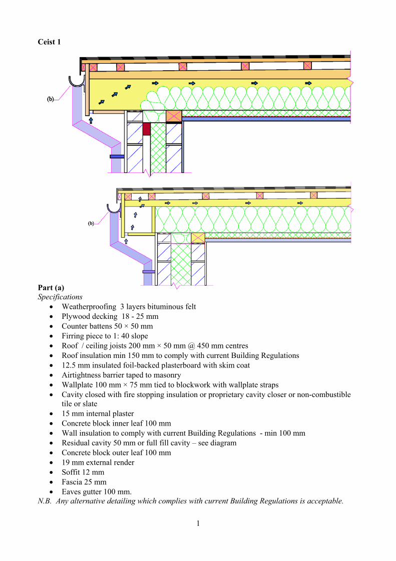
Ceist 1
Part (a) Specifications
• Weatherproofing 3 layers bituminous felt • Plywood decking 18 - 25 mm • Counter battens 50 × 50 mm • Firring piece to 1: 40 slope • Roof / ceiling joists 200 mm × 50 mm @ 450 mm centres • Roof insulation min 150 mm to comply with current Building Regulations • 12.5 mm insulated foil-backed plasterboard with skim coat • Airtightness barrier taped to masonry • Wallplate 100 mm × 75 mm tied to blockwork with wallplate straps • Cavity closed with fire stopping insulation or proprietary cavity closer or non-combustible
tile or slate • 15 mm internal plaster • Concrete block inner leaf 100 mm • Wall insulation to comply with current Building Regulations - min 100 mm • Residual cavity 50 mm or full fill cavity – see diagram • Concrete block outer leaf 100 mm • 19 mm external render • Soffit 12 mm • Fascia 25 mm • Eaves gutter 100 mm.
N.B. Any alternative detailing which complies with current Building Regulations is acceptable.

2
Part (b) How rainwater is removed from the flat roof
• A drip is formed with 50 mm × 25 mm batten to fascia • The felt is turned down over batten and directs the rainwater into the eaves gutter • Eaves gutter is fitted under drip and along the eaves of the roof • The firring piece creates a suitable slope to the roof surface • The eaves gutter is fixed to the fascia • Downpipe is fitted to the gutter and wall to convey the rainwater to ground level.
Ceist 2 Part (a) Insulating the cavity The procedure is carried out as follows:
• Holes of 22 mm diameter are drilled through the external leaf - or internal leaf if new build
• The holes are spaced at 800 mm horizontally and at 1350mm vertically
• Extra holes are drilled beneath window cills and above window / door heads
• This is to ensure proper filling of the cavity • The insulation is then pumped into the cavity • The injection of the insulation is carried out by a
specialist company • As the pumping takes place a light coating of glue is applied to the beads • When the glue sets, the beads will form a solid structure within the cavity • When the pumping is complete the holes are filled and painted to blend in with the existing
wall finish • The insulation material used is usually polystyrene beads.
Adding a system of insulation to the inside of the walls
• This system is formed using 50 mm × 50 mm battens fixed to the inside surface of the cavity wall
• The battens are spaced at 400mm centres • Insulation is placed in between the battens • Vapour barrier must be included. This may form part of the
plaster slab • Plasterboard of 12mm thickness is fitted to the battens • A skim coat of plaster is then applied
or • Insulated dry lining plasterboard may also be used and this is
glued to wall and mechanically fixed with metal fixings drilled and friction held in position
• Joints taped and filled and an emulsion paint is applied to the internal wall surface • This may be applied using roller or brush • The insulation used may be fibre glass, polystyrene or polyurethane, gutex, cork, hemp,
sheep’s wool etc.
3
Part (b) Two advantages of improving the insulation properties of external walls of the house
• Reduces the heat loss • The house will be warmer • Better indoor environment • Energy bills are reduced and better for the environment • It improves the U-value rating • It improves the Building Energy Rating.
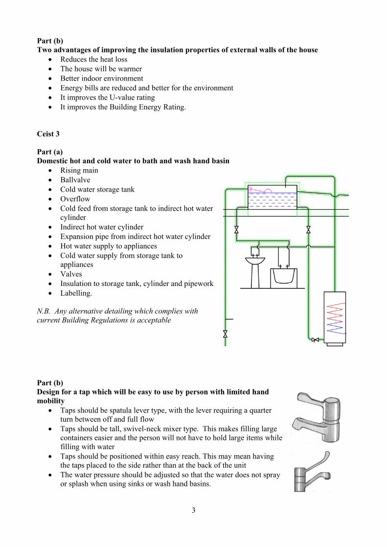
Ceist 3 Part (a) Domestic hot and cold water to bath and wash hand basin
• Rising main • Ballvalve • Cold water storage tank • Overflow • Cold feed from storage tank to indirect hot water
cylinder • Indirect hot water cylinder • Expansion pipe from indirect hot water cylinder • Hot water supply to appliances • Cold water supply from storage tank to
appliances • Valves • Insulation to storage tank, cylinder and pipework • Labelling.
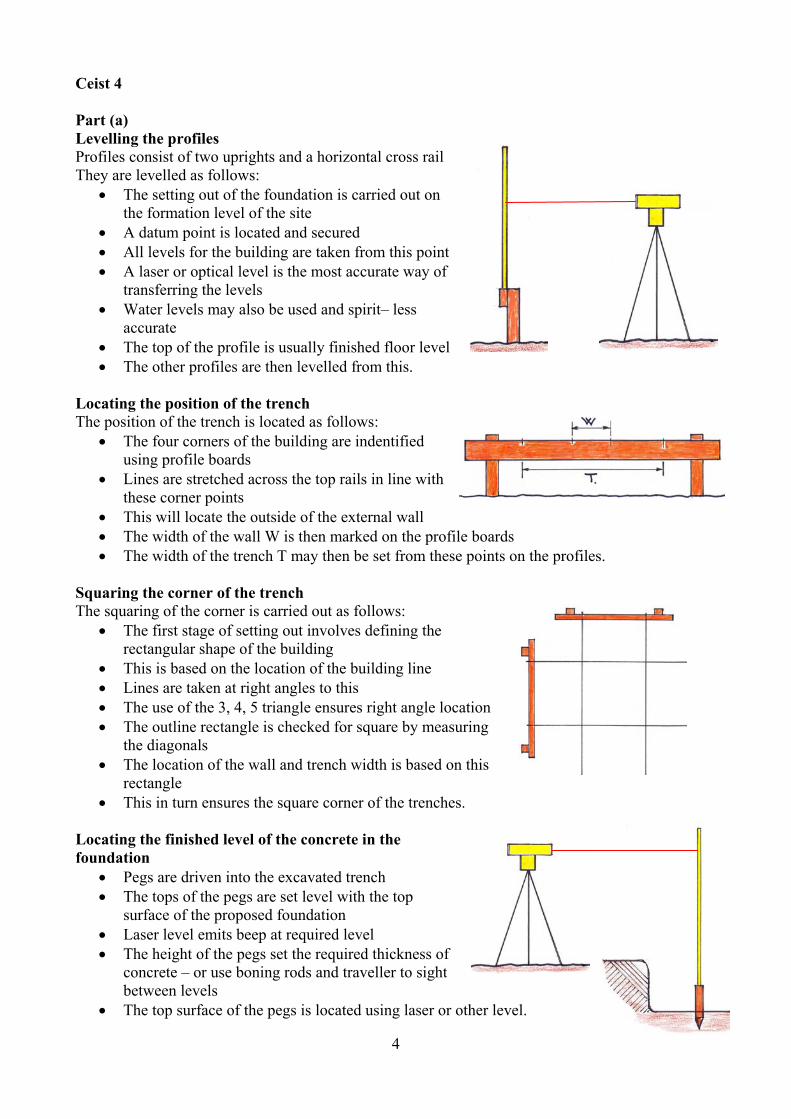
N.B. Any alternative detailing which complies with current Building Regulations is acceptable Part (b) Design for a tap which will be easy to use by person with limited hand mobility
• Taps should be spatula lever type, with the lever requiring a quarter turn between off and full flow
• Taps should be tall, swivel-neck mixer type. This makes filling large containers easier and the person will not have to hold large items while filling with water
• Taps should be positioned within easy reach. This may mean having the taps placed to the side rather than at the back of the unit
• The water pressure should be adjusted so that the water does not spray or splash when using sinks or wash hand basins.
4
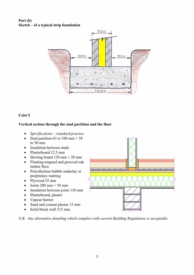
Ceist 4 Part (a) Levelling the profiles Profiles consist of two uprights and a horizontal cross rail They are levelled as follows:
• The setting out of the foundation is carried out on the formation level of the site
• A datum point is located and secured • All levels for the building are taken from this point • A laser or optical level is the most accurate way of
transferring the levels • Water levels may also be used and spirit– less
accurate • The top of the profile is usually finished floor level • The other profiles are then levelled from this.
Locating the position of the trench The position of the trench is located as follows:
• The four corners of the building are indentified using profile boards
• Lines are stretched across the top rails in line with these corner points
• This will locate the outside of the external wall • The width of the wall W is then marked on the profile boards • The width of the trench T may then be set from these points on the profiles.
Squaring the corner of the trench The squaring of the corner is carried out as follows:
• The first stage of setting out involves defining the rectangular shape of the building
• This is based on the location of the building line • Lines are taken at right angles to this • The use of the 3, 4, 5 triangle ensures right angle location • The outline rectangle is checked for square by measuring
the diagonals • The location of the wall and trench width is based on this
rectangle • This in turn ensures the square corner of the trenches.
Locating the finished level of the concrete in the foundation
• Pegs are driven into the excavated trench • The tops of the pegs are set level with the top
surface of the proposed foundation • Laser level emits beep at required level • The height of the pegs set the required thickness of
concrete – or use boning rods and traveller to sight between levels
• The top surface of the pegs is located using laser or other level.
5
Part (b) Sketch – of a typical strip foundation
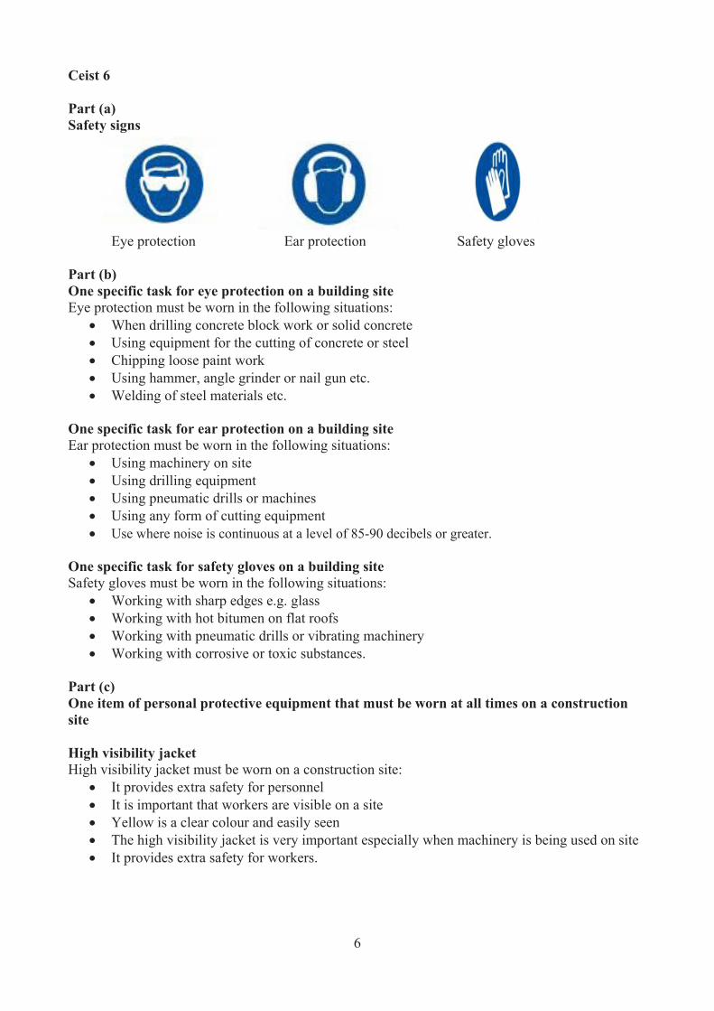
Ceist 5 Vertical section through the stud partition and the floor
• Specifications – standard practice • Stud partition 63 to 100 mm × 38
to 50 mm • Insulation between studs • Plasterboard 12.5 mm • Skirting board 120 mm × 20 mm • Floating tongued and grooved oak
timber floor • Polyethylene bubble underlay or
proprietary matting • Plywood 25 mm • Joists 200 mm × 50 mm • Insulation between joists 150 mm • Plasterboard, plaster • Vapour barrier • Sand and cement plaster 15 mm • Solid block wall 215 mm.
N.B. Any alternative detailing which complies with current Building Regulations is acceptable.
6
Ceist 6 Part (a) Safety signs
Eye protection Ear protection Safety gloves Part (b) One specific task for eye protection on a building site Eye protection must be worn in the following situations:
• When drilling concrete block work or solid concrete • Using equipment for the cutting of concrete or steel • Chipping loose paint work • Using hammer, angle grinder or nail gun etc. • Welding of steel materials etc.
One specific task for ear protection on a building site Ear protection must be worn in the following situations:
• Using machinery on site • Using drilling equipment • Using pneumatic drills or machines • Using any form of cutting equipment • Use where noise is continuous at a level of 85-90 decibels or greater.
One specific task for safety gloves on a building site Safety gloves must be worn in the following situations:
• Working with sharp edges e.g. glass • Working with hot bitumen on flat roofs • Working with pneumatic drills or vibrating machinery • Working with corrosive or toxic substances.
Part (c) One item of personal protective equipment that must be worn at all times on a construction site High visibility jacket High visibility jacket must be worn on a construction site:
• It provides extra safety for personnel • It is important that workers are visible on a site • Yellow is a clear colour and easily seen • The high visibility jacket is very important especially when machinery is being used on site • It provides extra safety for workers.
7
Safety helmet A safety helmet must be worn on a construction site:
• It protects the worker from falling objects • The safety helmet protects the head • It protects the worker if you hit your head against a solid object • The worker is visible because of the helmet colour • It provides extra safety for workers.
Steel cap boots Steel cap boots must be worn on a construction site:
• It provides extra safety for the worker on site • The steel cap provides protection for the toes • Many accidents occur on construction sites due to items falling on workers feet • It is a simple safe way of giving protection to the worker.
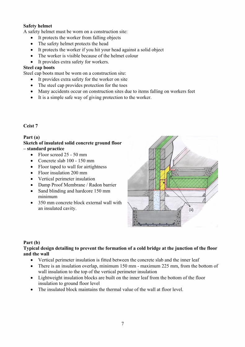
Ceist 7 Part (a) Sketch of insulated solid concrete ground floor – standard practice
• Floor screed 25 - 50 mm • Concrete slab 100 - 150 mm • Floor taped to wall for airtightness • Floor insulation 200 mm • Vertical perimeter insulation • Damp Proof Membrane / Radon barrier • Sand blinding and hardcore 150 mm
minimum • 350 mm concrete block external wall with
an insulated cavity.
Part (b) Typical design detailing to prevent the formation of a cold bridge at the junction of the floor and the wall
• Vertical perimeter insulation is fitted between the concrete slab and the inner leaf • There is an insulation overlap, minimum 150 mm - maximum 225 mm, from the bottom of
wall insulation to the top of the vertical perimeter insulation • Lightweight insulation blocks are built on the inner leaf from the bottom of the floor
insulation to ground floor level • The insulated block maintains the thermal value of the wall at floor level.
8
Part (c) Suitable floor covering for a bathroom on the ground floor of the house
Ceramic tiles
• Ceramic tiles are very durable and can withstand considerable wear
• Textured tiles are available and are less slippery than other floor coverings
• There is a very wide range of colours, shapes and designs
• This type floor is relatively inexpensive.
Vinyl
• Water will not easily discolour vinyl floor surface
• Vinyl resists scuffs, stains and moisture
• The surface is durable and easy to clean
• Vinyl is available with non slip resistant surface
• Vinyl is affordable and available wide variety of colours and patterns.
Cork tiling
• This surface is soft and has a warm feel on bare feet
• It is environmentally friendly • Cork tiling is resistant to mould,
mildew and bacteria • It naturally repels moisture • This floor requires low maintenance.
Heavy duty Linoleum
• This surface does not damage easily • It is environmentally friendly • The surface is easy to walk on.
Marmoleum
• Hard wearing, waterproof and durable • Resistant to dirt, scuff marks and
stains • Requires very little care • Used in schools, hospitals and
industry. Natural stone
• Stone is easy to care and durable • It is environmentally friendly.
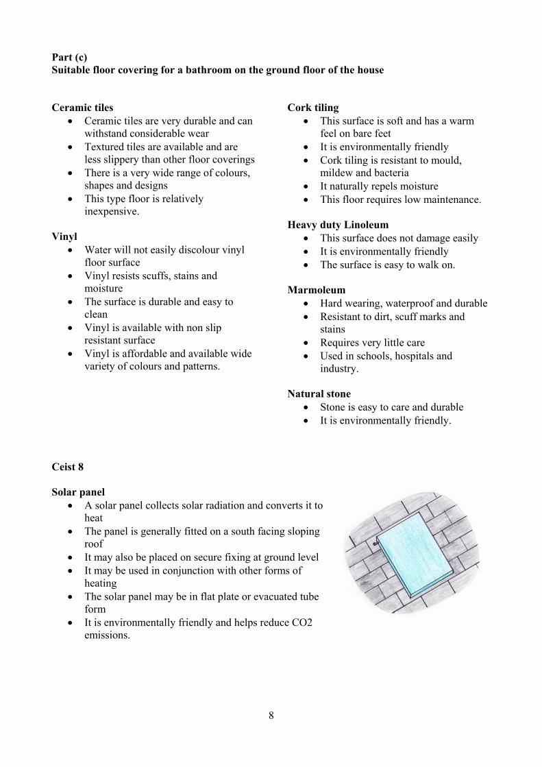
Ceist 8 Solar panel
• A solar panel collects solar radiation and converts it to heat
• The panel is generally fitted on a south facing sloping roof
• It may also be placed on secure fixing at ground level • It may be used in conjunction with other forms of
heating • The solar panel may be in flat plate or evacuated tube
form • It is environmentally friendly and helps reduce CO2
emissions.

9
Flue liner • It acts as a conduit, transferring the smoke from the fire or stove • The flue liner is built in as the construction of the chimney is carried out • A new flue liner may be fitted to an existing chimney when installing a
new stove or cooker • The general form of flue liner is made from ceramic clay • Flexible flue liners are made from stainless steel, available in various
sizes and lengths. Wind turbine
• This is a device that converts the energy of the wind into mechanical energy
• The mechanical energy is then used to generate electricity • Wind turbines may be used for small scale applications or for large scale
production of commercial electricity • Small wind turbines are used as auxiliary power on boats/caravans and
for charging batteries • Wind turbines are located to exploit the wind energy at a location • Wind is a clean source of energy • Wind turbines are made up of three main parts, blades, generator and
structural support tower. Dovetail halving joint
• The joint is similar to a Tee Halving joint • The dovetail slope is added • Half of the thickness is taken out of each piece • It is strong and resists pulling forces • It has a large gluing area • The slope is 1:8 for hardwoods • The slope is 1:6 for softwoods • This joint is widely used in woodwork.
Purlin
• This is the member A stretching under the rafters B • It provides support to the roof structure • The purlin is an important part of a traditional
cut roof • The purlin helps in the construction of attic
space development • The typical cross section size of a purlin is 150
x 75mm • It is supported by struts which transfer the
weight to an internal load bearing wall • The purlin may also be supported by means of
an RSJ.
10
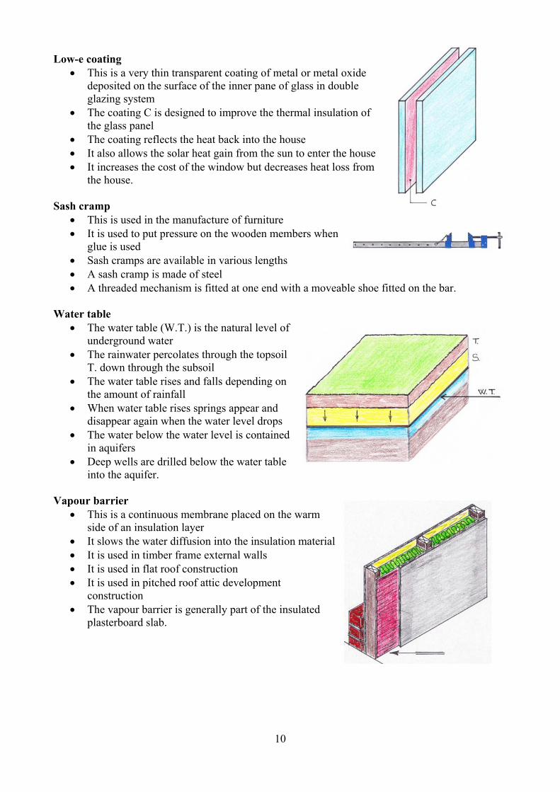
Low-e coating • This is a very thin transparent coating of metal or metal oxide
deposited on the surface of the inner pane of glass in double glazing system
• The coating C is designed to improve the thermal insulation of the glass panel
• The coating reflects the heat back into the house • It also allows the solar heat gain from the sun to enter the house • It increases the cost of the window but decreases heat loss from
the house. Sash cramp
• This is used in the manufacture of furniture • It is used to put pressure on the wooden members when
glue is used • Sash cramps are available in various lengths • A sash cramp is made of steel • A threaded mechanism is fitted at one end with a moveable shoe fitted on the bar.
Water table
• The water table (W.T.) is the natural level of underground water
• The rainwater percolates through the topsoil T. down through the subsoil
• The water table rises and falls depending on the amount of rainfall
• When water table rises springs appear and disappear again when the water level drops
• The water below the water level is contained in aquifers
• Deep wells are drilled below the water table into the aquifer.
Vapour barrier
• This is a continuous membrane placed on the warm side of an insulation layer
• It slows the water diffusion into the insulation material • It is used in timber frame external walls • It is used in flat roof construction • It is used in pitched roof attic development
construction • The vapour barrier is generally part of the insulated
plasterboard slab.
11
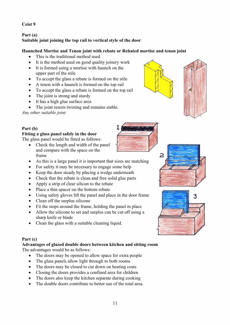
Ceist 9 Part (a) Suitable joint joining the top rail to vertical style of the door Haunched Mortise and Tenon joint with rebate or Rebated mortise and tenon joint
• This is the traditional method used • It is the method used on good quality joinery work • It is formed using a mortise with haunch on the
upper part of the stile • To accept the glass a rebate is formed on the stile • A tenon with a haunch is formed on the top rail • To accept the glass a rebate is formed on the top rail • The joint is strong and sturdy • It has a high glue surface area • The joint resists twisting and remains stable.
Any other suitable joint Part (b) Fitting a glass panel safely in the door The glass panel would be fitted as follows:
• Check the length and width of the panel and compare with the space on the frame
• As this is a large panel it is important that sizes are matching • For safety it may be necessary to engage some help • Keep the door steady by placing a wedge underneath • Check that the rebate is clean and free solid glue parts • Apply a strip of clear silicon to the rebate • Place a thin spacer on the bottom rebate • Using safety gloves lift the panel and place in the door frame • Clean off the surplus silicone • Fit the stops around the frame, holding the panel in place • Allow the silicone to set and surplus can be cut off using a
sharp knife or blade • Clean the glass with a suitable cleaning liquid.
Part (c)Advantages of glazed double doors between kitchen and sitting room The advantages would be as follows:
• The doors may be opened to allow space for extra people • The glass panels allow light through to both rooms • The doors may be closed to cut down on heating costs • Closing the doors provides a confined area for children • The doors also keep the kitchen separate during cooking • The double doors contribute to better use of the total area.
12
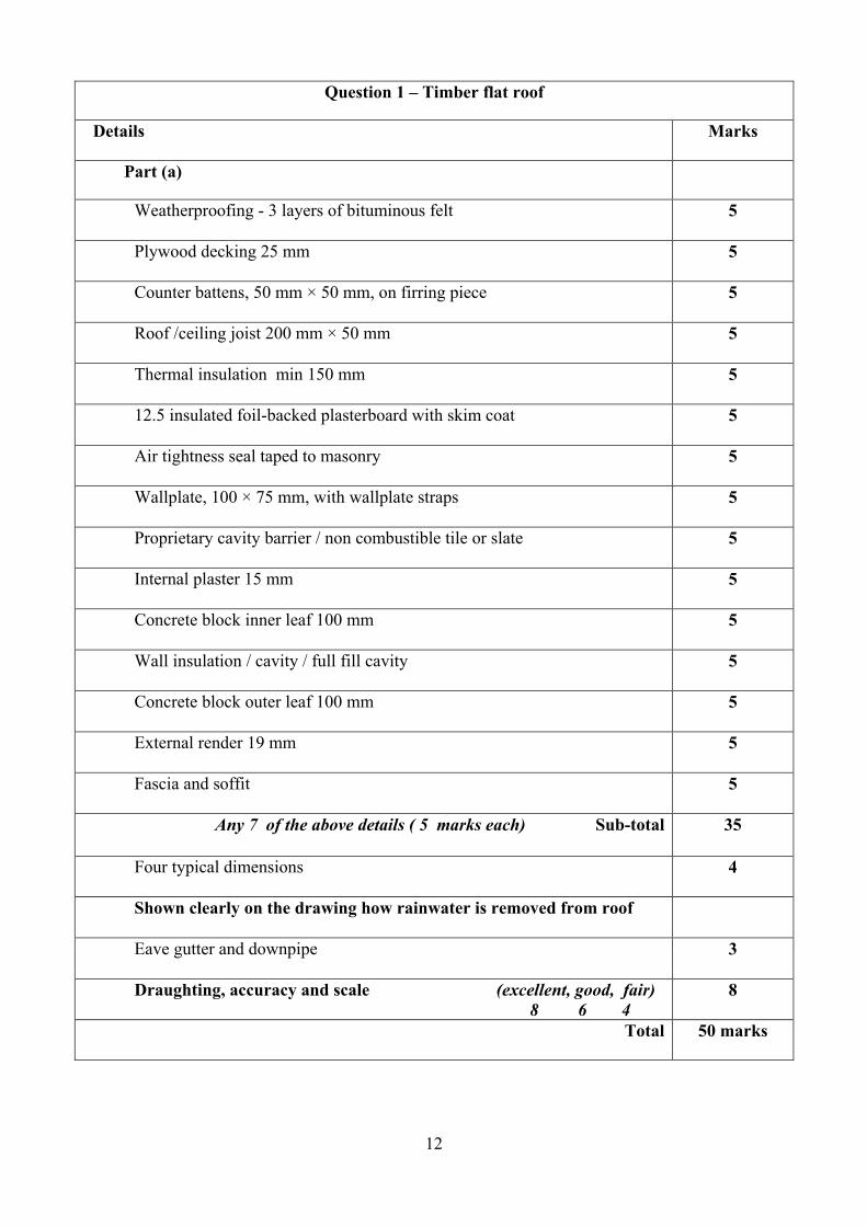
Question 1 – Timber flat roof
Details Marks
Part (a)
Weatherproofing - 3 layers of bituminous felt 5
Plywood decking 25 mm 5
Counter battens, 50 mm × 50 mm, on firring piece 5
Roof /ceiling joist 200 mm × 50 mm 5
Thermal insulation min 150 mm 5
12.5 insulated foil-backed plasterboard with skim coat 5
Air tightness seal taped to masonry 5
Wallplate, 100 × 75 mm, with wallplate straps 5
Proprietary cavity barrier / non combustible tile or slate 5
Internal plaster 15 mm 5
Concrete block inner leaf 100 mm 5
Wall insulation / cavity / full fill cavity 5
Concrete block outer leaf 100 mm 5
External render 19 mm 5
Fascia and soffit 5
Any 7 of the above details ( 5 marks each) Sub-total 35
Four typical dimensions 4
Shown clearly on the drawing how rainwater is removed from roof
Eave gutter and downpipe 3
Draughting, accuracy and scale (excellent, good, fair) 8 6 4
8
Total 50 marks
13
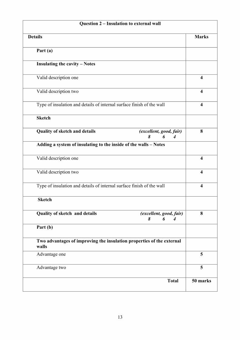
Question 2 – Insulation to external wall
Details Marks
Part (a)
Insulating the cavity – Notes
Valid description one 4
Valid description two
4
Type of insulation and details of internal surface finish of the wall 4
Sketch
Quality of sketch and details (excellent, good, fair) 8 6 4
8
Adding a system of insulating to the inside of the walls – Notes
Valid description one 4
Valid description two
4
Type of insulation and details of internal surface finish of the wall 4
Sketch
Quality of sketch and details (excellent, good, fair) 8 6 4
8
Part (b)
Two advantages of improving the insulation properties of the external walls
Advantage one 5
Advantage two 5
Total 50 marks
14
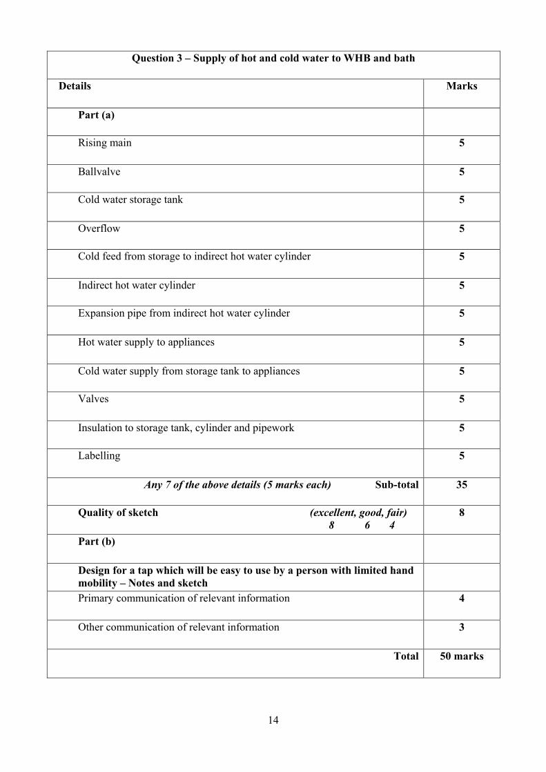
Question 3 – Supply of hot and cold water to WHB and bath
Details Marks
Part (a)
Rising main 5
Ballvalve 5
Cold water storage tank 5
Overflow 5
Cold feed from storage to indirect hot water cylinder 5
Indirect hot water cylinder 5
Expansion pipe from indirect hot water cylinder 5
Hot water supply to appliances 5
Cold water supply from storage tank to appliances 5
Valves 5
Insulation to storage tank, cylinder and pipework 5
Labelling 5
Any 7 of the above details (5 marks each) Sub-total 35
Quality of sketch (excellent, good, fair) 8 6 4
8
Part (b)
Design for a tap which will be easy to use by a person with limited hand mobility – Notes and sketch
Primary communication of relevant information 4
Other communication of relevant information 3
Total 50 marks
15
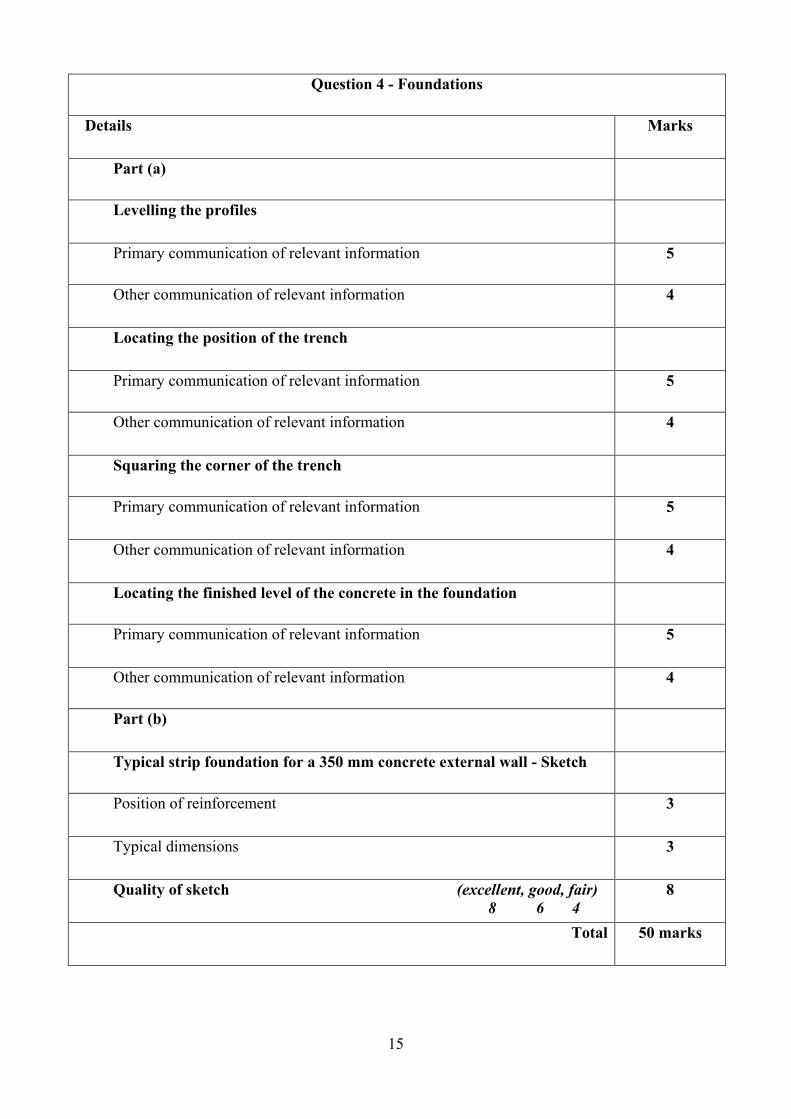
Question 4 - Foundations
Details Marks
Part (a)
Levelling the profiles
Primary communication of relevant information 5
Other communication of relevant information 4
Locating the position of the trench
Primary communication of relevant information 5
Other communication of relevant information 4
Squaring the corner of the trench
Primary communication of relevant information 5
Other communication of relevant information 4
Locating the finished level of the concrete in the foundation
Primary communication of relevant information 5
Other communication of relevant information 4
Part (b)
Typical strip foundation for a 350 mm concrete external wall - Sketch
Position of reinforcement 3
Typical dimensions 3
Quality of sketch (excellent, good, fair) 8 6 4
8
Total 50 marks
16
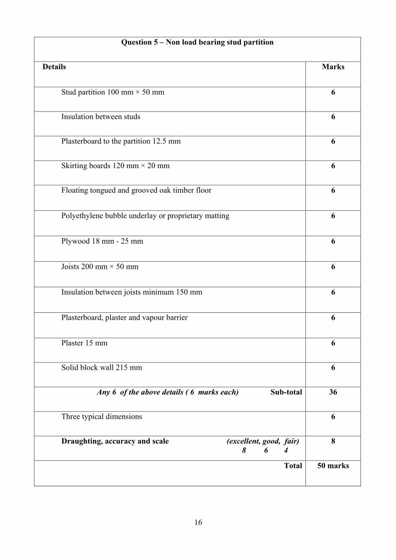
Question 5 – Non load bearing stud partition
Details Marks
Stud partition 100 mm × 50 mm 6
Insulation between studs 6
Plasterboard to the partition 12.5 mm 6
Skirting boards 120 mm × 20 mm 6
Floating tongued and grooved oak timber floor 6
Polyethylene bubble underlay or proprietary matting 6
Plywood 18 mm - 25 mm 6
Joists 200 mm × 50 mm 6
Insulation between joists minimum 150 mm 6
Plasterboard, plaster and vapour barrier 6
Plaster 15 mm 6
Solid block wall 215 mm 6
Any 6 of the above details ( 6 marks each) Sub-total 36
Three typical dimensions 6
Draughting, accuracy and scale (excellent, good, fair) 8 6 4
8
Total 50 marks
17
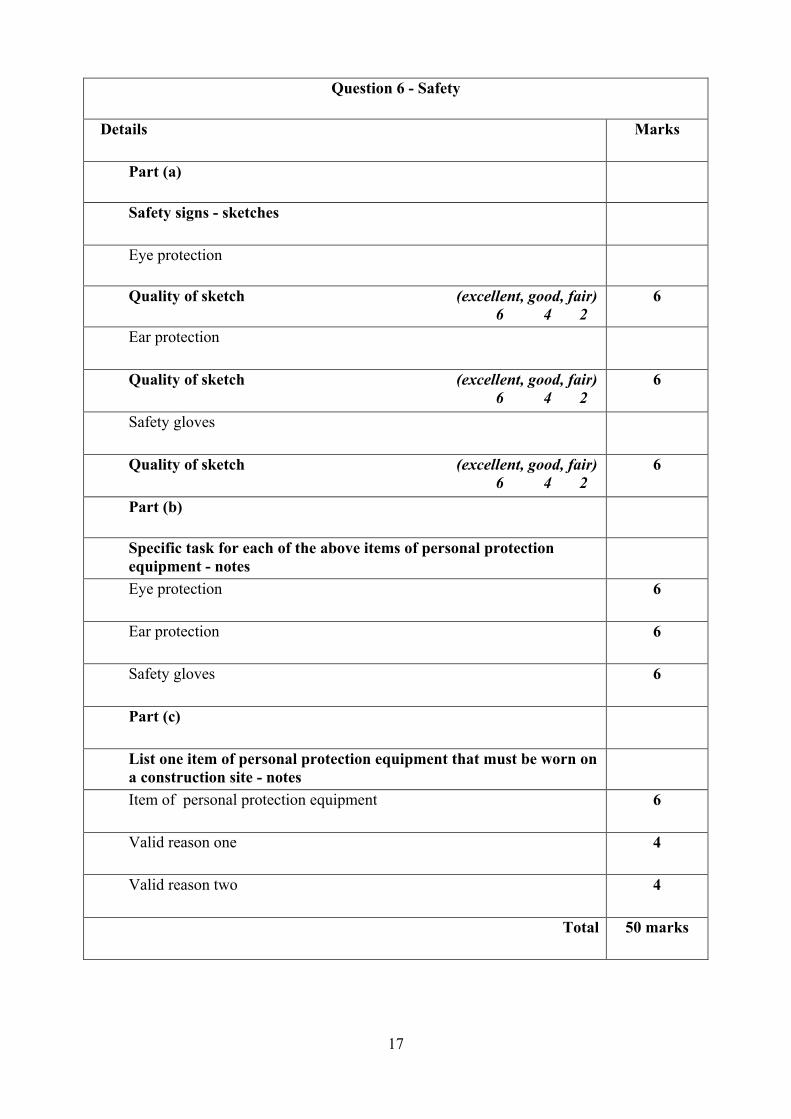
Question 6 - Safety
Details Marks
Part (a)
Safety signs - sketches
Eye protection
Quality of sketch (excellent, good, fair) 6 4 2
6
Ear protection
Quality of sketch (excellent, good, fair) 6 4 2
6
Safety gloves
Quality of sketch (excellent, good, fair) 6 4 2
6
Part (b)
Specific task for each of the above items of personal protection equipment - notes
Eye protection 6
Ear protection 6
Safety gloves 6
Part (c)
List one item of personal protection equipment that must be worn on a construction site - notes
Item of personal protection equipment 6
Valid reason one 4
Valid reason two 4
Total 50 marks

18
Question 7 – Insulated solid concrete ground floor
Details Marks
Part (a)
Design details at junction of the floor and wall - notes
Valid detail one 4
Valid detail two 4
Three typical dimensions 6
Design details at junction of the floor and wall - sketch
Labelling the floor components and other details 8
Quality of sketch (excellent, good, fair) 8 6 4
8
Part (b)
Design detail to prevent the formation of a cold bridge at the junction of the floor and the wall
Shown on sketch 5
Part (c)
Suitable floor covering for a bathroom
Type of floor covering 5
Reasons for your choice of floor covering
Reason one 5
Reason two 5
Total 50 marks

19
Question 8 - Terms
Details Marks
Item one
Primary communication of relevant information 6
Other communication of relevant information 4
Item two
Primary communication of relevant information 6
Other communication of relevant information 4
Item three
Primary communication of relevant information 6
Other communication of relevant information 4
Item four
Primary communication of relevant information 6
Other communication of relevant information 4
Item five
Primary communication of relevant information 6
Other communication of relevant information 4
Total 50 marks
20
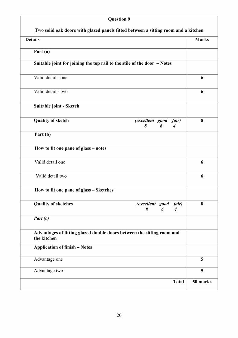
Question 9
Two solid oak doors with glazed panels fitted between a sitting room and a kitchen
Details Marks
Part (a)
Suitable joint for joining the top rail to the stile of the door – Notes
Valid detail - one 6
Valid detail - two 6
Suitable joint - Sketch
Quality of sketch (excellent good fair) 8 6 4
8
Part (b)
How to fit one pane of glass – notes
Valid detail one 6
Valid detail two 6
How to fit one pane of glass – Sketches
Quality of sketches (excellent good fair) 8 6 4
8
Part (c)
Advantages of fitting glazed double doors between the sitting room and the kitchen
Application of finish – Notes
Advantage one 5
Advantage two 5
Total
50 marks

Blank Page
ScrúLeav
ScM(150
StaiTria ConPra
CoimState
údú naving C
céimMark
0 marc)
idéarail Ph
nstruactica
misiún nExamin
a hArdCertific
m Mhing
r Foirhrati
uctional Tes
na Scrnations
dteistimcate Ex
harcSch
rgníoiciúil
n Studst
úduithCommi
méireaxamin
cálaheme
ochta
dies
he Stáitission
chta 2ation 2
a e
a
t
2013 2013

Note: The arteHoweveWhere thapplies. Compon
efact is to ber the use ohere is evi
nent is mar
CMark
be hand prof a batteridence of
rked out o
Construcking Sc
roduced bry poweredthe use of
of 50% of
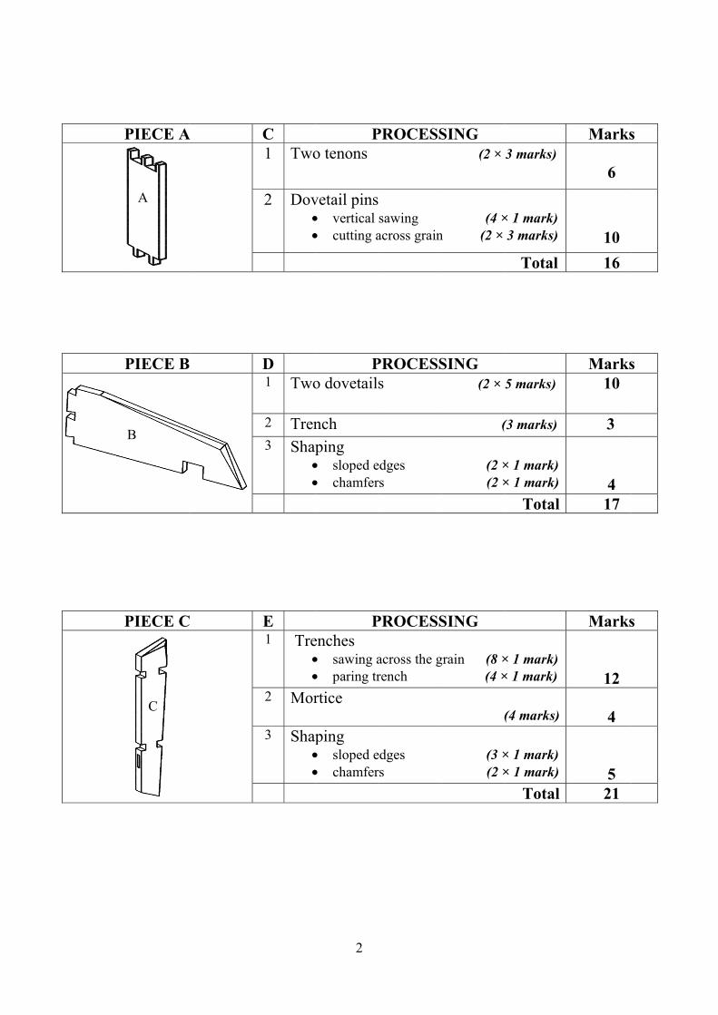
B 1 Piec
••
2 Piec•
•3 Piec
•
•
4 Piec•
•
5 Piec••
A
1 Ove
2 Dow
3 Des edg
1
ction Stheme –
by candidad screwdrf machiner
the marks
Mce A • dovetail• tenons ce B • joints - d -
• slopes ance C • joints - t
- m• slopes an
ce D • joints - t
- m• slopes, c
ce E • joint- ten• slopes
OVER
erall qualit
wel locate
sign and apges • design • shaping
tudies 2– Practic
ates withouriver is allory for a pa
s available
MARKING
s
dovetails trench
nd chamfer
trenches mortice nd chamfer
trench mortices chamfers &
non
RALL AS
ty of assem
d and fitte
pplied sha
g
2013 cal Test
ut the assiowed. articular pr
e for that p
G OUT
(2 × (2 ×
(2 × (
s (4 ×
(4 × (
s (5 ×
( (2 × curve (5 ×
(2 (2 ×
SSEMBLY
mbled arte
ed correctl
aping to
t
istance of
rocedure a
procedure.
3 marks) 2 marks)
3 marks) (2 marks) × 1 mark)
2 marks) (2 marks) 1 mark)
(2 marks) 2 marks)
× 1 mark)
2 marks) × 1 mark)
Total
Y
efact
ly
(3 marks) (4 marks)
Total
machinery
a penalty
.
Marks
10
12
15
11
452
MARK
8
4
7
19
y.
s
KS
P
P
P
PIECE A
PIECE B
PIECE C
A
B
C
A
C
C 1 Two
2 Dov••
D 1 Two
2 Tren3 Shap
••
E 1 Tre
••
2 Mor
3 Shap••
2
Po tenons
vetail pins• vertical • cutting a
Po dovetails
nch ping
• sloped e• chamfer
Penches • sawing a• paring trrtice
ping • sloped e• chamfer
PROCESS
sawing across grain
PROCESSs
edges rs
PROCESS across the grench
edges rs
SING (2 ×
(4 ×
n (2 ×
SING (2 ×
(
(2 × (2 ×
SING
grain (8 × (4 ×
(
(3 × (2 ×
3 marks)
× 1 mark) 3 marks)
Total
5 marks)
(3 marks)
× 1 mark) × 1 mark)
Total
× 1 mark) × 1 mark)
(4 marks)
× 1 mark) × 1 mark)
Total
Marks
6
10 16
Marks10
3
4 17
Marks
12
4
521
s
s
s
P
P
PIECE D
PIECE - E
D
E
D
E
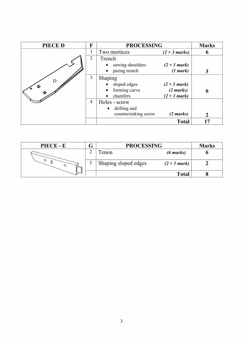
F 1 Two2 Tre
••
3 Sha•••
4 Hol
G 2 Ten
3 Shap
3
Po morticesench • sawing s• paring traping • sloped e• forming• chamferles - screw• drilling
counter
P
non
ping slope
PROCESSs shoulders rench
edges g curve rs
w g and rsinking scr
PROCESS
ed edges
SING (2 × (2 ×
(2 × (2 (2 ×
rew (
SING (6
(2 ×
3 marks)
× 1 mark) (1 mark)
× 1 mark) 2 marks)
× 1 mark)
(2 marks) Total
marks)
× 1 mark)
Total
Marks6
3
6
2 17
Marks6
2
8
s
s

Blank Page

Blank Page

Blank Page