Embed Size (px)
Citation preview

1
MECH 466Microelectromechanical Systems
University of VictoriaDept. of Mechanical Engineering
Lecture 10:Piezoresistivity
© N. Dechev, University of Victoria
2
Design of Piezoresistive Sensors with Micro-Beams
Stress Distribution in Thin Plates
Design of Piezoresistive Sensors with Thin Plates
Piezoresistivity Overview
© N. Dechev, University of Victoria

3© N. Dechev, University of Victoria
The maximum strain in a beam occurs in the location where the moment is highest.
Recall from Lecture 5, the stress for a beam in a state of ‘pure bending’ is:
where:
Since stress and strain are related by: , the strain at that point in the beam is:
Design of Piezoresistive Sensors with Micro-Beams
4© N. Dechev, University of Victoria
Four Cases of Maximum Stress and Strain(for cantilever beams of rectangular cross-section)
Consider the following points on a cantilever beam:
Free End
A
B
C
D
E
F
G
H
I
J
Fixed End

5© N. Dechev, University of Victoria
Four Cases of Maximum Stress and Strain(for cantilever beams of rectangular cross-section)
Case 1: Beam in Pure Tension:
Stress or strain at all points is equal
6© N. Dechev, University of Victoria
Four Cases of Maximum Stress and Strain(for cantilever beams of rectangular cross-section)
Case 2: Beam in Pure Bending about the x-axis:
z
yx
Stress or strain is greatest at points A,B,C, E:
7© N. Dechev, University of Victoria
Four Cases of Maximum Stress and Strain(for cantilever beams of rectangular cross-section)
Case 3: Beam in Pure Bending about the z-axis:
z
yxStress or strain is greatest at: points A (compression),points C, D, E (tension):
8© N. Dechev, University of Victoria
Four Cases of Maximum Stress and Strain(for cantilever beams of rectangular cross-section)
Case 4: Beam in Torsion (twist) about the y-axis:
z
yxT
‘Shear stress’ or ‘shear strain’ is greatest at points: B,G (assuming pure torsion)
See Table in Lecture 5, page 22 for equations for shear strain at either point B or G (or any point between them along a line)
9© N. Dechev, University of Victoria
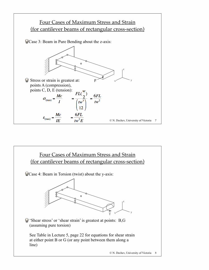
Example: Resistance Change due to Applied Force
See Class Notes for Solution
Question: What is the percentage change in resistance, given the applied load F?
z
x y
w
t
F
L
a
b
10© N. Dechev, University of Victoria
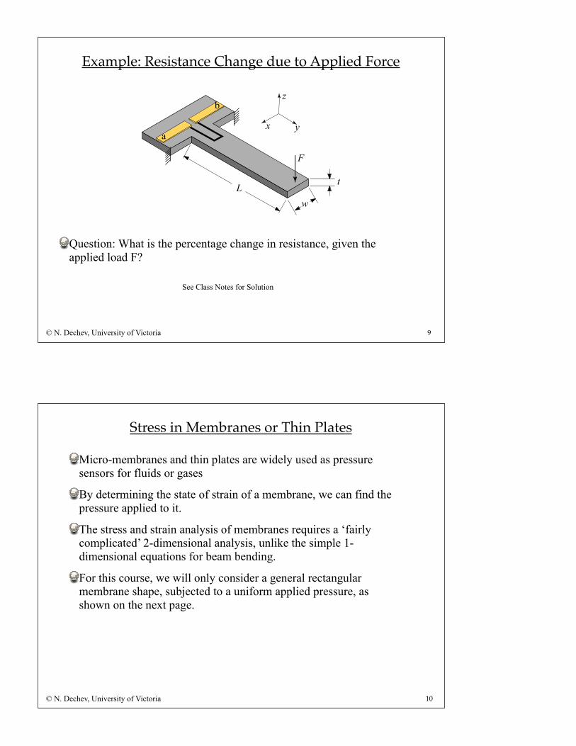
Micro-membranes and thin plates are widely used as pressure sensors for fluids or gases
By determining the state of strain of a membrane, we can find the pressure applied to it.
The stress and strain analysis of membranes requires a ‘fairly complicated’ 2-dimensional analysis, unlike the simple 1-dimensional equations for beam bending.
For this course, we will only consider a general rectangular membrane shape, subjected to a uniform applied pressure, as shown on the next page.
Stress in Membranes or Thin Plates

11© N. Dechev, University of Victoria
We assume that a ‘uniform pressure’ is applied to the top surface.
Recall the FEM analysis from Lecture 10:
Stress and Displacement of Square Membranes
Top View Side View
Top View
12© N. Dechev, University of Victoria
The following ‘empirical’ formula can be used, along with Table-L11, on page 14 of these notes.
(NOTE: Table 6.10 in the textbook is incorrect.)
The formula for maximum stress (at edges) is:
Stress and Displacement of Square Membranes

13© N. Dechev, University of Victoria
The formula for stress at the center of the plate is:
The formula for displacement of the plate in the center is:
We can find the strain by using the relation:
Stress and Displacement of Square Membranes
14© N. Dechev, University of Victoria
a/b 1.0 1.2 1.4 1.6 1.8 2.0 ∞
β1 0.3078 0.3834 0.4356 0.4680 0.4872 0.4974 0.5000
β2 0.1386 0.1794 0.2094 0.2286 0.2406 0.2472 0.2500
α 0.0138 0.0188 0.0226 0.0251 0.0267 0.0277 0.0284
Stress and Displacement of Square Membranes
Table L11: Constants for bending of Rectangular Plate under a Uniform pressure load:
Table Reference: “Roark’s Formulas for Stress and Strain”, 7th edition, Warren C. Young, Richard G. Budynas, McGraw-Hill, 1989, Page 508.

15© N. Dechev, University of Victoria
Example 2: Resistance Change of Pressure Sensor
P1 P2w
Top View:
Doped Resistor
Side View:
L
Consider a rectangular membrane fabricated with silicon crystal using bulk micromachining. A doped resistor has been fabricated into one edge, as shown below:
Question: If the membrane is 4 um thick, and there is a pressure difference of (P2 - P1) 1000 kPa from one side to the other, what is the new resistance?
16© N. Dechev, University of Victoria
See Class Notes for Solution
Example 2: Resistance Change of Pressure Sensor
17© N. Dechev, University of Victoria
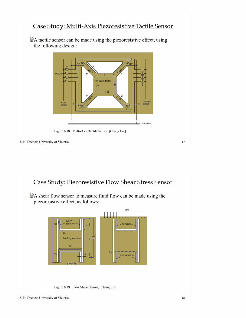
Case Study: Multi-Axis Piezoresistive Tactile Sensor
A tactile sensor can be made using the piezoresistive effect, using the following design:
Figure 6.18. Multi-Axis Tactile Sensor, [Chang Liu]
18© N. Dechev, University of Victoria
Case Study: Piezoresistive Flow Shear Stress Sensor
A shear flow sensor to measure fluid flow can be made using the piezoresistive effect, as follows:
Figure 6.19. Flow Shear Sensor, [Chang Liu]


![6th International Conference on Composite Testing and Model ...Epoxy vinyl ester Derakane Momentum 470-300 Solution casting [1] Cyclic tension and compression piezoresistivity of carbon](https://img.pdfslide.net/doc/110x75/611ca78bf053547b9a48fb33/6th-international-conference-on-composite-testing-and-model-epoxy-vinyl-ester.jpg)