Embed Size (px)
Citation preview
Lecture 12: NMT, GSM, UMTS
Anders Västberg
08-790 44 55
Slides are a selection from the slides from chapter 10 from:http://williamstallings.com/Wireless/Wireless2e.html
1G: NMT
• 1981 Nordic Mobile Telephone • First generation analog technology
– NMT450 and NMT900– Free standard ready 1973, 1977– Network open 1981 in Sweden and Norway
• NMT450 covers 500000 km2 area in Sweden (including surrounding waters)
• Analog traffic channel, digital control channel• Not encrypted
Differences Between First and Second Generation Systems
• Digital traffic channels – first-generation systems are almost purely analog; second-generation systems are digital
• Encryption – all second generation systems provide encryption to prevent eavesdropping
• Error detection and correction – second-generation digital traffic allows for detection and correction, giving clear voice reception
• Channel access – second-generation systems allow channels to be dynamically shared by a number of users
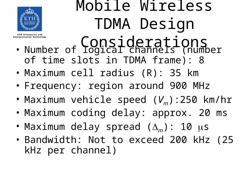
Mobile Wireless TDMA Design Considerations
• Number of logical channels (number of time slots in TDMA frame): 8
• Maximum cell radius (R): 35 km• Frequency: region around 900 MHz• Maximum vehicle speed (Vm):250 km/hr• Maximum coding delay: approx. 20 ms• Maximum delay spread (m): 10 s• Bandwidth: Not to exceed 200 kHz (25 kHz per
channel)
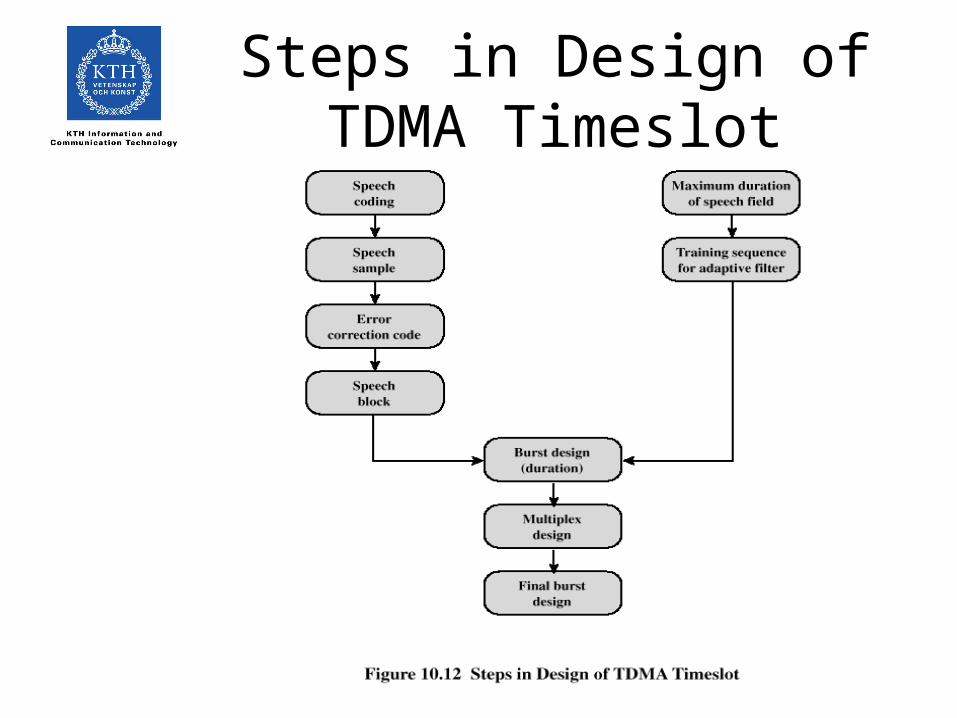
Steps in Design of TDMA Timeslot
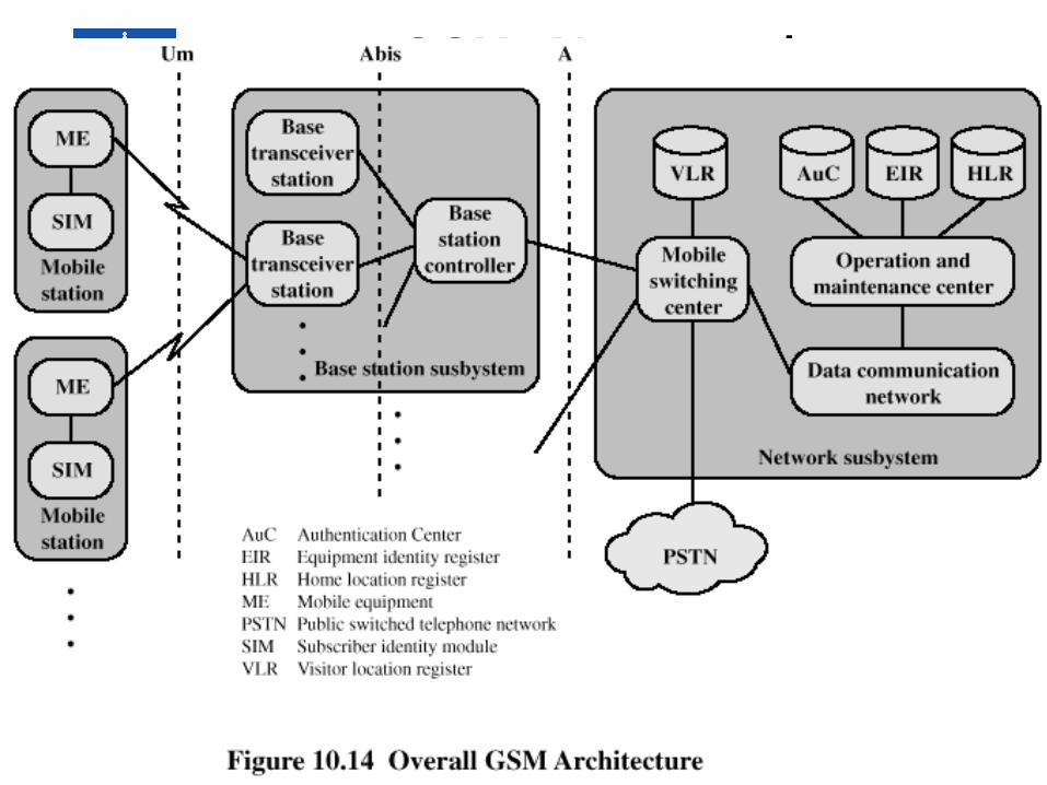
GSM Network Architecture
Mobile Station
• Mobile station communicates across Um interface (air interface) with base station transceiver in same cell as mobile unit
• Mobile equipment (ME) – physical terminal, such as a telephone or PCS– ME includes radio transceiver, digital signal processors and
subscriber identity module (SIM)
• GSM subscriber units are generic until SIM is inserted– SIMs roam, not necessarily the subscriber devices
Base Station Subsystem (BSS)
• BSS consists of base station controller and one or more base transceiver stations (BTS)
• Each BTS defines a single cell– Includes radio antenna, radio transceiver and a link
to a base station controller (BSC)
• BSC reserves radio frequencies, manages handoff of mobile unit from one cell to another within BSS, and controls paging
Network Subsystem (NS)
• NS provides link between cellular network and public switched telecommunications networks– Controls handoffs between cells in different BSSs
– Authenticates users and validates accounts
– Enables worldwide roaming of mobile users
• Central element of NS is the mobile switching center (MSC)
Mobile Switching Center (MSC) Databases
• Home location register (HLR) database – stores information about each subscriber that belongs to it
• Visitor location register (VLR) database – maintains information about subscribers currently physically in the region
• Authentication center database (AuC) – used for authentication activities, holds encryption keys
• Equipment identity register database (EIR) – keeps track of the type of equipment that exists at the mobile station
TDMA Format – Time Slot Fields
• Trail bits – allow synchronization of transmissions from mobile units
• Encrypted bits – encrypted data• Stealing bit - indicates whether block contains data or
is "stolen"• Training sequence – used to adapt parameters of
receiver to the current path propagation characteristics– Strongest signal selected in case of multipath propagation
• Guard bits – used to avoid overlapping with other bursts
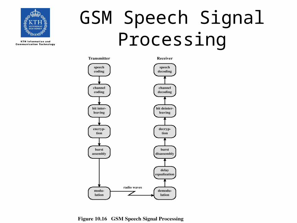
GSM Speech Signal Processing
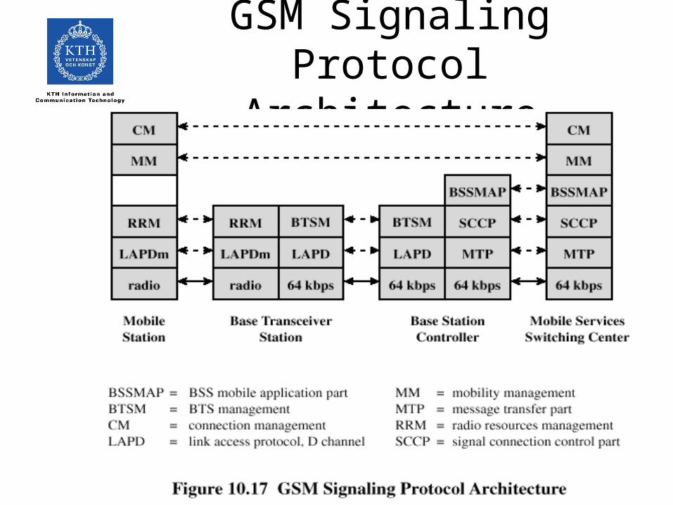
GSM Signaling Protocol Architecture
Functions Provided by Protocols
• Protocols above the link layer of the GSM signaling protocol architecture provide specific functions:– Radio resource management– Mobility management– Connection management– Mobile application part (MAP)– BTS management
2.5G
• GPRS: General Packet Radio Service– Bitrates from 9.05 to 171.2 kbit/s depending of
number of Time slots allocated and coding scheme.
• EDGE: Enhanced data rates for GSM evolution– Data rates up to 384 kbit/s by using 8 PSK
Advantages of CDMA Cellular
• Frequency diversity – frequency-dependent transmission impairments have less effect on signal
• Multipath resistance – chipping codes used for CDMA exhibit low cross correlation and low autocorrelation
• Privacy – privacy is inherent since spread spectrum is obtained by use of noise-like signals
• Graceful degradation – system only gradually degrades as more users access the system
Drawbacks of CDMA Cellular
• Self-jamming – arriving transmissions from multiple users not aligned on chip boundaries unless users are perfectly synchronized
• Near-far problem – signals closer to the receiver are received with less attenuation than signals farther away
• Soft handoff – requires that the mobile acquires the new cell before it relinquishes the old; this is more complex than hard handoff used in FDMA and TDMA schemes
Mobile Wireless CDMA Design Considerations
• RAKE receiver – when multiple versions of a signal arrive more than one chip interval apart, RAKE receiver attempts to recover signals from multiple paths and combine them– This method achieves better performance than simply
recovering dominant signal and treating remaining signals as noise
• Soft Handoff – mobile station temporarily connected to more than one base station simultaneously
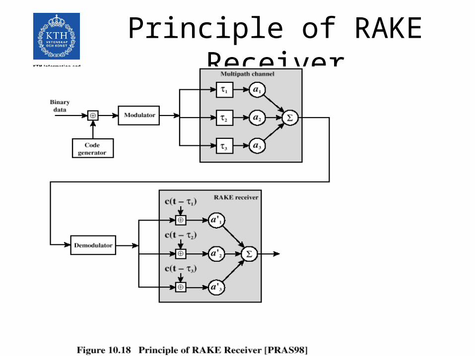
Principle of RAKE Receiver
ITU’s View of Third-Generation Capabilities
• Voice quality comparable to the public switched telephone network
• 144 kbps data rate available to users in high-speed motor vehicles over large areas
• 384 kbps available to pedestrians standing or moving slowly over small areas
• Support for 2.048 Mbps for office use• Symmetrical / asymmetrical data transmission rates• Support for both packet switched and circuit switched
data services
ITU’s View of Third-Generation Capabilities
• An adaptive interface to the Internet to reflect efficiently the common asymmetry between inbound and outbound traffic
• More efficient use of the available spectrum in general
• Support for a wide variety of mobile equipment• Flexibility to allow the introduction of new services
and technologies
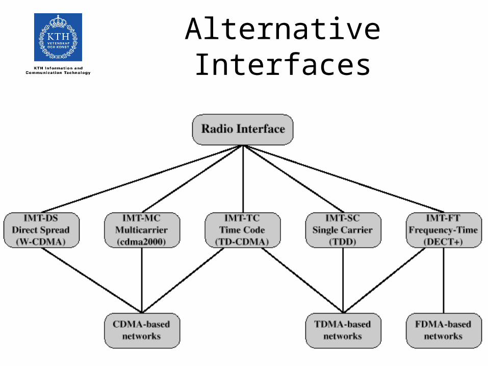
Alternative Interfaces
CDMA Design Considerations
• Bandwidth – limit channel usage to 5 MHz• Chip rate – depends on desired data rate, need for
error control, and bandwidth limitations; 3 Mcps or more is reasonable
• Multirate – advantage is that the system can flexibly support multiple simultaneous applications from a given user and can efficiently use available capacity by only providing the capacity required for each service
UMTS
• Wideband CDMA
• Uplink 1920-1980 MHz
• Downlink 2110-2170 MHz
• Bandwidth 4,4-5 MHz
• HSDPA: High Speed Downlink Packet Access– Data rates: 1,8, 3,6, 7,2 and 14,4 Mbit/s