Embed Size (px)
Citation preview

V. DEMENKO MECHANICS OF MATERIALS 2020
9/8/2020 2:10:01 PM W:\+МЕХАНИКА МАТЕРИАЛОВ W\++НМКД АНГЛ\082 LECTURES 2020\03 Principal Hypotheses and Assumptions in Mechanics of Materials.doc
1
LECTURE 3 Principal Hypotheses and Assumptions in Mechanics of Materials. Deformations, Internal Forces and Stresses.
Fundamental principles of strength of materials are based on laws and theorems
of general mechanics and generally on laws of solid bodies statics.
Theoretical mechanics deals with bodies which are called absolute solid (rigid)
bodies. In contrast to theoretical mechanics, the mechanics of materials deals with
deformable solids.
1 Principal Hypotheses in Mechanics of Materials
The principal hypotheses for deformable solids are following:
1. The material of a structure is considered to be continuous at all points of the
body, i.e. we have got a continuous medium. Due to continuity’s property it is possible
to apply infinitesimal analysis to such a medium.
2. The material of structure is considered to be homogeneous at all points of the
body, i.e. a body possesses the same properties at all points.
3. A continuous medium is taken to be isotropic, i.e. possessing the same
properties in all directions. Isotropic materials include metals, concrete, and some
types of plastics. Materials possessing different properties in different directions are
called anisotropic. For example, wood, composites etc.
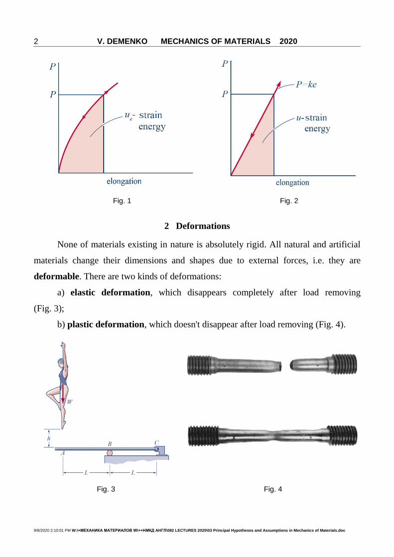
4. All bodies are assumed to be ideally elastic if their deformations return to zero
after removing the applied forces (see Figs 1, 2).
5. Deformations of elastic bodies under the action of external loads are not
significant comparing to the dimensions of bodies, i.e. at elastic deformation the body
dimensions are not changed substantially. It allows applying the equilibrium equations
without changing the geometrical dimensions of the structure, i.e. to apply external
forces to non-deformable structure.
6. Generally, the displacements of solid bodies are proportional to acting forces
within certain limits, i.e. the solid is assumed to be linearly elastic (Fig. 2). In
nonproportional relationship between forces and displacements solid is assumed to be
nonlinearly elastic (Fig. 1).
V. DEMENKO MECHANICS OF MATERIALS 2020
9/8/2020 2:10:01 PM W:\+МЕХАНИКА МАТЕРИАЛОВ W\++НМКД АНГЛ\082 LECTURES 2020\03 Principal Hypotheses and Assumptions in Mechanics of Materials.doc
2
Fig. 1 Fig. 2
2 Deformations
None of materials existing in nature is absolutely rigid. All natural and artificial
materials change their dimensions and shapes due to external forces, i.e. they are
deformable. There are two kinds of deformations:
a) elastic deformation, which disappears completely after load removing
(Fig. 3);
b) plastic deformation, which doesn't disappear after load removing (Fig. 4).
Fig. 3 Fig. 4

V. DEMENKO MECHANICS OF MATERIALS 2020
9/8/2020 2:10:01 PM W:\+МЕХАНИКА МАТЕРИАЛОВ W\++НМКД АНГЛ\082 LECTURES 2020\03 Principal Hypotheses and Assumptions in Mechanics of Materials.doc
3
3 External Forces
If a structure is considered separately from surrounding bodies it is affected by
forces which are defined as external forces. According to the natural distribution of
external forces over the body, the latter are divided into:
a) body forces, which are distributed over the volume of a body and are applied
to each of its particles (body forces comprise, for example, the force of gravity, forces
of magnetic attraction, centrifugal forces) (Fig. 5);
b) surface forces, which act on portions of surface (forces of wind, pressure)
(Figs 6, 7, 8);
c) forces distributing along a line (Figs 9, 10);
d) concentrated forces, which are applied over the relatively small surface
(Figs 11, 12);
e) couples of forces or concentrated moments (Figs 13, 14);
f) distributed moments (Figs 15, 16).
It is usual to distinguish static loads, dynamic loads, cyclic loads.
Static loads act on a structure continuously (see Fig. 17); dynamic loads act on a
structure during short interval of time (see Figs 18, 19). Cyclic loads can be changed by
a specified law (see Fig. 20).
4 Internal Forces
External forces produce strains and internal elastic forces which appear in all
points of deformable solid and withstand changing the body shape and volume. Internal
forces are proportional to external ones (hypothesis of linear elasticity).
If a solid body is in natural state (without external forces application), then internal
forces are assumed to be zero (hypothesis of non-stressed state).
5 Method of Sections
The method of sections and equations of equilibrium enable to determine the
magnitude of internal forces that appear under the action of external forces. Consider
in Fig. 21 the application of method of sections to a body, balanced by a system of
external forces
1F , 2F ,…, nF . (1)

V. DEMENKO MECHANICS OF MATERIALS 2020
9/8/2020 2:10:01 PM W:\+МЕХАНИКА МАТЕРИАЛОВ W\++НМКД АНГЛ\082 LECTURES 2020\03 Principal Hypotheses and Assumptions in Mechanics of Materials.doc
4
Fig. 5 Fig. 6
Fig. 7 Fig. 8
Fig. 9 Fig. 10

V. DEMENKO MECHANICS OF MATERIALS 2020
9/8/2020 2:10:01 PM W:\+МЕХАНИКА МАТЕРИАЛОВ W\++НМКД АНГЛ\082 LECTURES 2020\03 Principal Hypotheses and Assumptions in Mechanics of Materials.doc
5
Fig. 11 Fig. 12
Fig. 13 Fig. 14
Fig. 15 Fig. 16
Fig. 17 Fig. 18

V. DEMENKO MECHANICS OF MATERIALS 2020
9/8/2020 2:10:01 PM W:\+МЕХАНИКА МАТЕРИАЛОВ W\++НМКД АНГЛ\082 LECTURES 2020\03 Principal Hypotheses and Assumptions in Mechanics of Materials.doc
6
Fig. 19 Fig. 20
It is evident, that the 1F , 2F , …, nF are satisfying the conditions of equilibrium.
The essence of method consists of the following four procedures:
1. The body analyzed is divided mentally by a plane including the point where
the internal forces must be determined;
2. One of the portions of the body is
named as rejected part (part II in Fig. 21);
3. The effect of rejected part is replaced by
internal forces so that the remaining part (I) is in
equilibrium;
4. The equations of equilibrium are
developed for the forces acting on the remaining
part of the body to calculate internal forces in the
cross-section.
Cut the body with a plane and reject the right-hand part, replacing the effect of
the rejected part to the remaining left-hand part by means of internal elastic forces. R ,
RM are the main vector and main moment of internal forces by means of which the
rejected part of the body acts on the remaining part according to third Newton’s law
(Fig. 22).
Fig. 21

V. DEMENKO MECHANICS OF MATERIALS 2020
9/8/2020 2:10:01 PM W:\+МЕХАНИКА МАТЕРИАЛОВ W\++НМКД АНГЛ\082 LECTURES 2020\03 Principal Hypotheses and Assumptions in Mechanics of Materials.doc
7
It is usual to reduce R and RM
toward centroid of a section. We choose a
system of coordinates x, y, z. Let x axis be
normal toward the section with y and z
axes within its plane (see Fig. 22).
The remaining part is in equilibrium,
i.e. the system of forces
( 1F , 2F , kF , …, , RR M ) (2)
satisfies the conditions of equilibrium. By projecting the resultant force vector R and
the resultant moment vector RM on the axes x, y and z we obtain six components (three
forces and three moments). These components of the main vector and main moment of
internal forces, appearing on a cross section of a bar, are called internal force factors
(internal forces) acting in that section.
The equilibrium conditions of the remaining part give us six equations of
equilibrium, determining internal force factors:
1
0k
ii
F R
; 01
0k
i Ri
M F M
. (3)
or in projections:
1
k
x ixi
N F
, 01
k
x ixi
M M F
,
1
k
y iyi
Q F
, 01
k
y iyi
M M F
, (4)
1
k
z izi
Q F
, 01
k
z izi
M M F
,
where normal to the section component of internal forces xN is called normal force in
the section. The forces yQ and zQ lying in the cross-section are called transverse or
Fig. 22

V. DEMENKO MECHANICS OF MATERIALS 2020
9/8/2020 2:10:01 PM W:\+МЕХАНИКА МАТЕРИАЛОВ W\++НМКД АНГЛ\082 LECTURES 2020\03 Principal Hypotheses and Assumptions in Mechanics of Materials.doc
8
shearing forces. The moment directed toward normal axis, xM , is called twisting
moment (torsional moment). Moments yM and zM are called bending moments
with respect to y and z axes (see Fig. 23).
When external forces are known, all internal force factors are obtained using six
equilibrium equations – they can be composed for any cut portion of a rod (I or II).
Fig. 23
In mechanics of materials we deal with the structural elements named as rod.
Any structural element having one cross-sectional dimension (length) 10 times and
more greater than remaining two ones will be assumed as a rod. An examples of
engineering structures consisting of the rods are represented in Fig. 24.
Structural elements named as plate and shell are also considered in mechanics of
materials (Figs 25, 26), but only under simplest types of loading.

V. DEMENKO MECHANICS OF MATERIALS 2020
9/8/2020 2:10:01 PM W:\+МЕХАНИКА МАТЕРИАЛОВ W\++НМКД АНГЛ\082 LECTURES 2020\03 Principal Hypotheses and Assumptions in Mechanics of Materials.doc
9

V. DEMENKO MECHANICS OF MATERIALS 2020
9/8/2020 2:10:01 PM W:\+МЕХАНИКА МАТЕРИАЛОВ W\++НМКД АНГЛ\082 LECTURES 2020\03 Principal Hypotheses and Assumptions in Mechanics of Materials.doc
10
Fig. 24 Examples of structural elements named by a rod
Fig. 25 Examples of structural elements named by a plate
Fig. 26 Examples of structural elements named by a shell
6 Concept of Stress
In order to characterize the law of internal forces distribution over the section a
measure of their intensity should be introduced. The measure used is stress.
Fig. 27

V. DEMENKO MECHANICS OF MATERIALS 2020
9/8/2020 2:10:01 PM W:\+МЕХАНИКА МАТЕРИАЛОВ W\++НМКД АНГЛ\082 LECTURES 2020\03 Principal Hypotheses and Assumptions in Mechanics of Materials.doc
11
Consider an arbitrary cross-section A of elastic body (Fig. 27). We isolate an
element of area A enclosing a point the internal force [N]P is acting on. The
average stress on the area 2[m ]A is taken to be
avP
pA
. (5)
We reduce the area A by contracting it to the point K. Since the medium is
continuous, a limiting process is applied as 0A . In the limit we obtain
0limA
P dPp
A dA
. (6)
The vector quantity of true stress p represents the intensity of internal forces
distribution at the point K within section A.
Stress has the dimension of force divided by area. The SI unit of stress is Pascal:
2
NPa
m or megaPascal: 6MPa 10 Pa.
Fig. 28
The stress in given point of a section considered as a vector quantity, i.e. it is
characterized by magnitude and direction.
Let us resolve the total stress vector into two components: one, directed along the
normal to the section and the other one, lying in the section plane (see Fig. 28).
Stress component directed along the normal to the section is called normal
stress and designated with greek letter . The component lying in the section plane
will be called the tangential (shearing) stress and designated with greek letter .

V. DEMENKO MECHANICS OF MATERIALS 2020
9/8/2020 2:10:01 PM W:\+МЕХАНИКА МАТЕРИАЛОВ W\++НМКД АНГЛ\082 LECTURES 2020\03 Principal Hypotheses and Assumptions in Mechanics of Materials.doc
12
7 Relations Between Stresses and Internal Forces
Fig. 29
In majority of cases, it is convenient to resolve the total stress into three
components directed parallel to coordinate axes. For the point in the cross section of a
bar it is shown in Fig. 29. For these components, the following rule of subscripts has
been adopted: the first subscript corresponds the coordinate axis perpendicular to the
plane; the second subscript gives the coordinate axis to which the given stress is
parallel. According to this rule, normal stresses should be written with two subscripts,
i.e. xx , but usually one of two subscripts is omitted.
Let us establish how the stresses and internal force factors in a bar cross section
are interrelated. Multiplying the stresses x , xz and xy by the area dA, we obtain
elementary internal forces:
,,
.
x x
y xy
z xz
dN dAdQ dA
dQ dA
(7)
Summing these elementary forces over the area of the section we find expressions for
main vector components of internal forces:
,
,
.
x x
A
y xy
A
z xz
A
N dA
Q dA
Q dA
(8)
Multiplying each of the elementary forces by the distance to the corresponding axis, we
obtain the elementary moments of internal forces:

V. DEMENKO MECHANICS OF MATERIALS 2020
9/8/2020 2:10:01 PM W:\+МЕХАНИКА МАТЕРИАЛОВ W\++НМКД АНГЛ\082 LECTURES 2020\03 Principal Hypotheses and Assumptions in Mechanics of Materials.doc
13
,
,
.
dM dA y dA zx xz xy
dM dA zy xdM dA yz x
(9)
Summing the elementary moments over the entire area of the section, we get the
expressions for main moment components of internal forces:
,
,
.
A
A
A
M z y dAx xy xz
M zdAy x
M ydAz x
(10)
These formulas will be used in the further discussion for solving one of the
principal problems in the theory of strength of materials: the determination of stresses
with known internal force factors.
8 Saint-Venant's Principle
The features of external forces application are manifested, as a rule, at
distances not exceeding the characteristic dimensions of bar cross section
(see Fig. 30).
Fig. 30
Therefore one should neglect the portion of the bar located in the zone of
external forces application if you will estimate internal stresses in the bar using the
methods of mechanics of materials. Example of Saint-Venant’s principle is illustrated

V. DEMENKO MECHANICS OF MATERIALS 2020
9/8/2020 2:10:01 PM W:\+МЕХАНИКА МАТЕРИАЛОВ W\++НМКД АНГЛ\082 LECTURES 2020\03 Principal Hypotheses and Assumptions in Mechanics of Materials.doc
14
by Fig. 31, where vicinity of P-force application is the Saint-Venant’s zone with non-
uniform stress distribution.
Fig. 31
9 Principle of Superposition
Since deformations the mechanics of materials deals with, are relatively small
(elastic), external forces may be assumed to act independently from one another, i.e.
the deformations and internal forces appearing in elastic bodies do not depend on the
order the external forces are applied in. Besides, the total effect of the whole system of
forces acting on a body is assumed to be the sum of effects produced by each force
separately. This is the principle of superposition.
10 Construction of Internal Force Factors Diagrams
A graph (plot) of internal force factor distribution along the length of bar is
called diagram. There are some rules of significant importance for diagrams
constructing:
1. Diagrams of internal force factors are always constructed on axial line which is
parallel to axial line of a bar.
2. The force factor magnitude is laid off along a normal to the axis.
3. The diagrams include denominations, dimensions, signs, numerical information.