Embed Size (px)
Citation preview
1
MECH 466Microelectromechanical Systems
University of VictoriaDept. of Mechanical Engineering
Lecture 4:Basic Review of Stress and Strain, Mechanics
of Beams
© N. Dechev, University of Victoria
2
Compliant Mechanisms
Basics of Mechanics of Materials
Bending of Beams
Stress within Beams
Moment of Inertia
Appendices:
(A) Stress and Strain
(B) Poisson’s Ratio
(C) Stress Tensor
(D) Strain Tensor
Overview
© N. Dechev, University of Victoria
3
Design of Micro-Mechanisms
In order to utilize the ‘mechanical’ aspect of MEMS devices, most MEMS devices must be capable of ‘motion’.
In other words, most micro-mechanical devices are ‘micro-mechanisms’, and we can apply the concepts of kinematics and dynamics when they are designed.
However, there are three fundamental differences between ‘macro-mechanisms’ and ‘micro-mechanisms’.
(a) Component Design Limitations (2D shapes only)
-Cannot make: Ball Bearings, Roller bearings, etc...
(b) Minimum Feature Size and Tolerance
(c) Stiction
-High ratio surface adhesion vs. volumetric forces.
© N. Dechev, University of Victoria
4
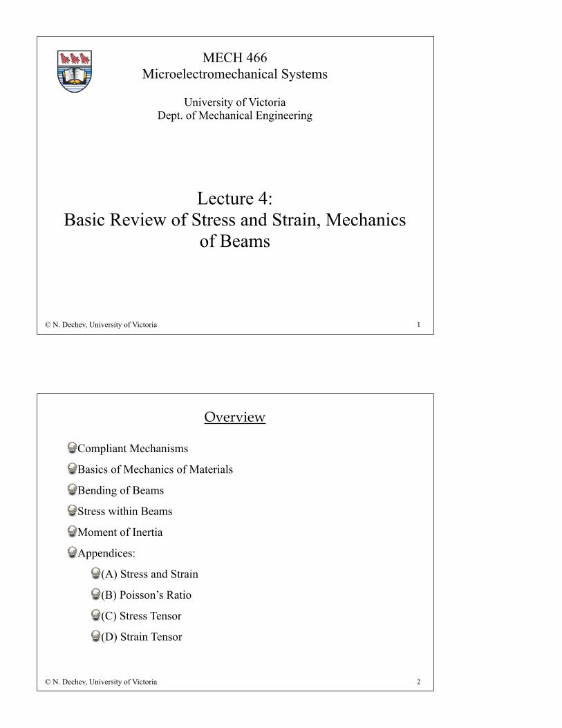
Compliant Mechanisms
In order to overcome most of these problems, many MEMS devices are designed as ‘compliant mechanisms’.
Compliant mechanisms are a class of mechanisms that do not use any traditional joints (i.e. revolute, slider, prismatic, etc...), but instead use flexible ‘spring like’ joints to allow their constituent parts to translate and rotate.
The simplest example of a compliant mechanism is a common spring:
© N. Dechev, University of Victoria
5
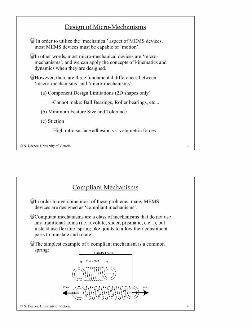
Compliant Mechanisms
A more complex example of a compliant mechanism is that of a ‘four bar linkage’:
Consider the benefits of compliant mechanisms in general, and how they apply to micro-devices.
© N. Dechev, University of Victoria
6
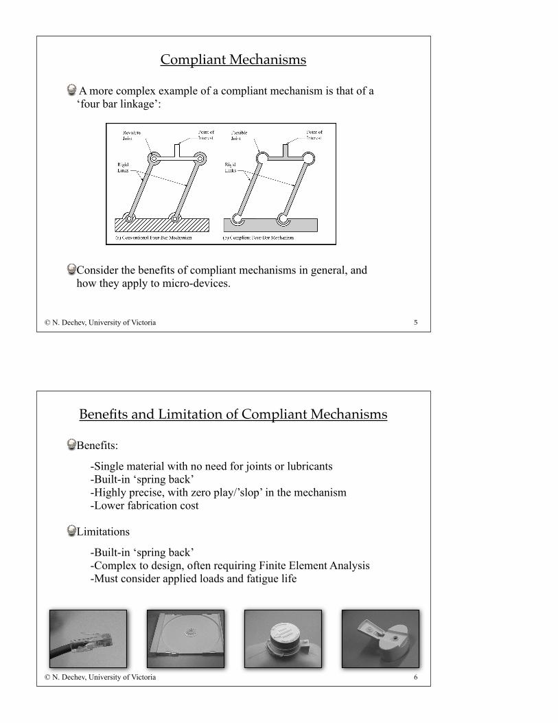
Benefits and Limitation of Compliant Mechanisms
Benefits:
-Single material with no need for joints or lubricants-Built-in ‘spring back’-Highly precise, with zero play/’slop’ in the mechanism-Lower fabrication cost
Limitations
-Built-in ‘spring back’-Complex to design, often requiring Finite Element Analysis-Must consider applied loads and fatigue life
© N. Dechev, University of Victoria
7
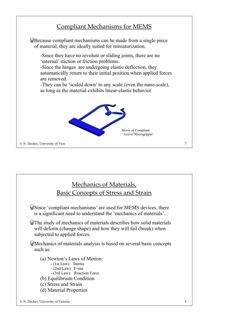
Compliant Mechanisms for MEMS
Because compliant mechanisms can be made from a single piece of material, they are ideally suited for miniaturization.
-Since they have no revolute or sliding joints, there are no ‘internal’ stiction or friction problems.-Since the hinges are undergoing elastic deflection, they automatically return to their initial position when applied forces are removed.-They can be ‘scaled down’ to any scale (even the nano-scale), as long as the material exhibits linear-elastic behavior.
© N. Dechev, University of Victoria
Movie of Compliant ‘Active’ Microgripper
8
Mechanics of Materials,Basic Concepts of Stress and Strain
Since ‘compliant mechanisms’ are used for MEMS devices, there is a significant need to understand the ‘mechanics of materials’.
The study of mechanics of materials describes how solid materials will deform (change shape) and how they will fail (break) when subjected to applied forces.
Mechanics of materials analysis is based on several basic concepts such as:
(a) Newton’s Laws of Motion:- (1st Law): Inertia- (2nd Law): F=ma- (3rd Law): Reaction Force
(b) Equilibrium Condition(c) Stress and Strain(d) Material Properties
© N. Dechev, University of Victoria
9
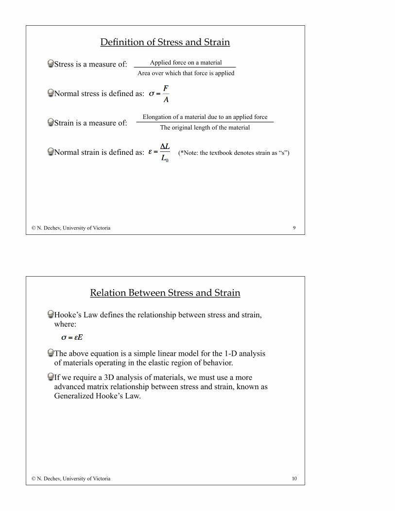
Definition of Stress and Strain
Stress is a measure of:
Normal stress is defined as:
Strain is a measure of:
Normal strain is defined as:
© N. Dechev, University of Victoria
Applied force on a materialArea over which that force is applied
Elongation of a material due to an applied forceThe original length of the material
(*Note: the textbook denotes strain as “s”)
10
Relation Between Stress and Strain
Hooke’s Law defines the relationship between stress and strain, where:
The above equation is a simple linear model for the 1-D analysis of materials operating in the elastic region of behavior.
If we require a 3D analysis of materials, we must use a more advanced matrix relationship between stress and strain, known as Generalized Hooke’s Law.
© N. Dechev, University of Victoria
11
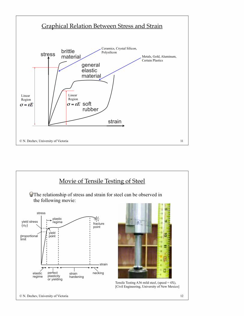
Graphical Relation Between Stress and Strain
© N. Dechev, University of Victoria
!"#$$%&'($&"#(%)$"&))
)$"(#*
+&*&"(%&%()$#,'($&"#(%
)-.$"/!!&"
LinearRegion
Ceramics, Crystal Silicon,Polysilicon
Metals, Gold, Aluminum,Certain Plastics
LinearRegion
12
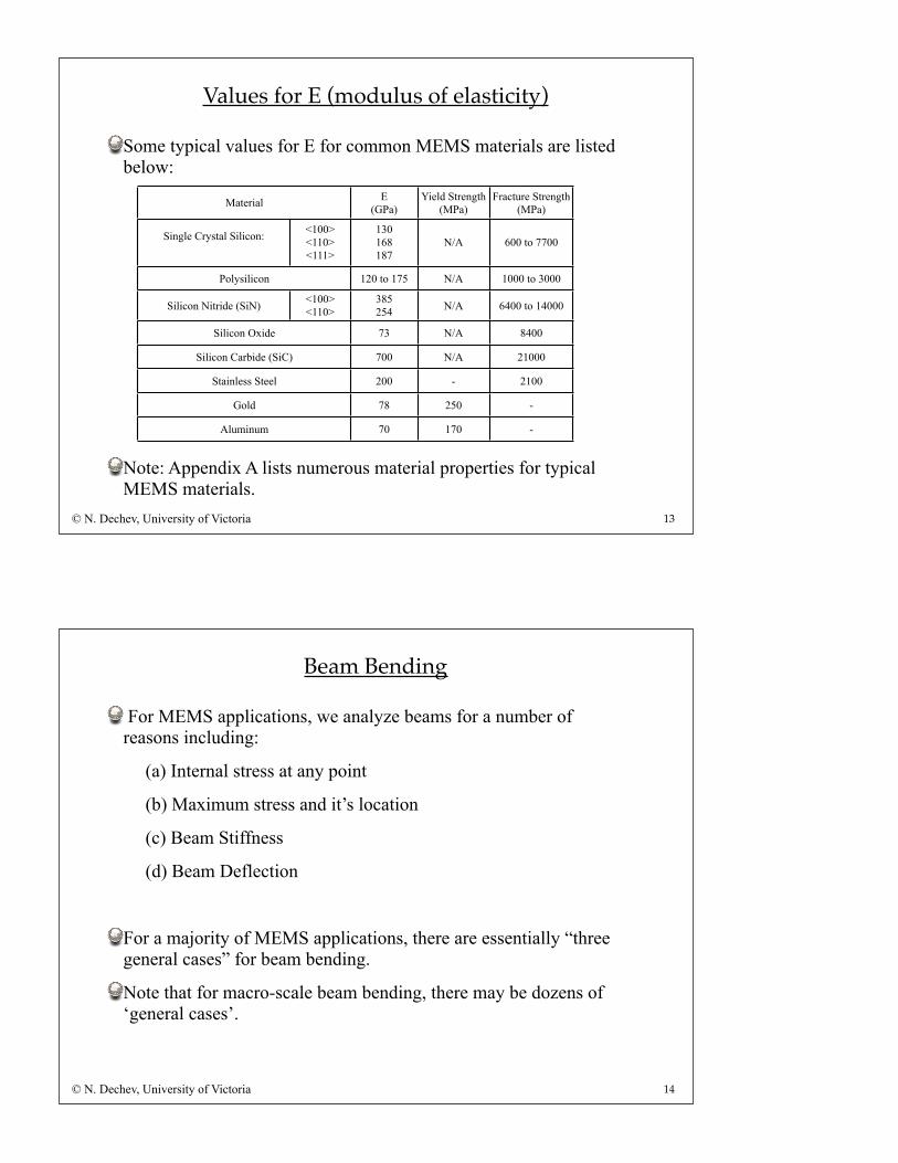
Movie of Tensile Testing of Steel
The relationship of stress and strain for steel can be observed in the following movie:
© N. Dechev, University of Victoria
!"#$!!
!"#%&'(%#)$'&'*
+#%,"-#$./&'"
0&$1)2!"#$!!3!04
!"#%&'
.#/./#"&/'%11&5&"
$1%!"&,#$*&5$
.$#+$,"
.1%!"&,&"0/#20&$1)&'*
'$,6&'*
.1%!"&,#$*&5$
0&$1)./&'"
Tensile Testing A36 mild steel, (speed = 4X),[Civil Engineering, University of New Mexico]
13
Values for E (modulus of elasticity)
Some typical values for E for common MEMS materials are listed below:
Note: Appendix A lists numerous material properties for typical MEMS materials.
© N. Dechev, University of Victoria
Material E(GPa)
Yield Strength(MPa)
Fracture Strength(MPa)
Single Crystal Silicon: <100><110><111>
130168187
N/A 600 to 7700
Polysilicon 120 to 175 N/A 1000 to 3000
Silicon Nitride (SiN) <100><110>
385254 N/A 6400 to 14000
Silicon Oxide 73 N/A 8400
Silicon Carbide (SiC) 700 N/A 21000
Stainless Steel 200 - 2100
Gold 78 250 -
Aluminum 70 170 -
14
Beam Bending
For MEMS applications, we analyze beams for a number of reasons including:
(a) Internal stress at any point
(b) Maximum stress and it’s location
(c) Beam Stiffness
(d) Beam Deflection
For a majority of MEMS applications, there are essentially “three general cases” for beam bending.
Note that for macro-scale beam bending, there may be dozens of ‘general cases’.
© N. Dechev, University of Victoria
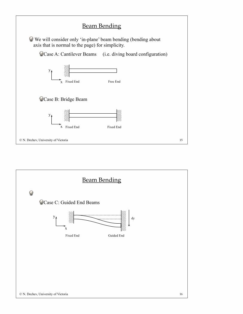
We will consider only ‘in-plane’ beam bending (bending about axis that is normal to the page) for simplicity.
Case A: Cantilever Beams (i.e. diving board configuration)
Case B: Bridge Beam
15
Beam Bending
© N. Dechev, University of Victoria
y
x Fixed End Free End
y
x Fixed End Fixed End
Case C: Guided End Beams
16
Beam Bending
© N. Dechev, University of Victoria
Fixed End Guided End
y
x
dy
(1) Determine all forces and moments using static equilibrium conditions
(2) Create diagrams for:
-Axial Force
-Shear Force
-Bending Moment
(3) Develop equation for stress at any point in the beam
(4) Develop equations for K (stiffness) and d (deflection) for the beam.
17
Analysis of Beams:
© N. Dechev, University of Victoria
18
Example of Beam Axial, Shear and Moment Diagrams:
© N. Dechev, University of Victoria
See Class Notes
19
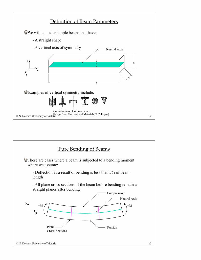
Definition of Beam Parameters
© N. Dechev, University of Victoria
We will consider simple beams that have:
- A straight shape
- A vertical axis of symmetry
Examples of vertical symmetry include:
y
zx
w
h
l
t
Neutral Axis
Cross-Sections of Various Beams[image from Mechanics of Materials, E. P. Popov]
20
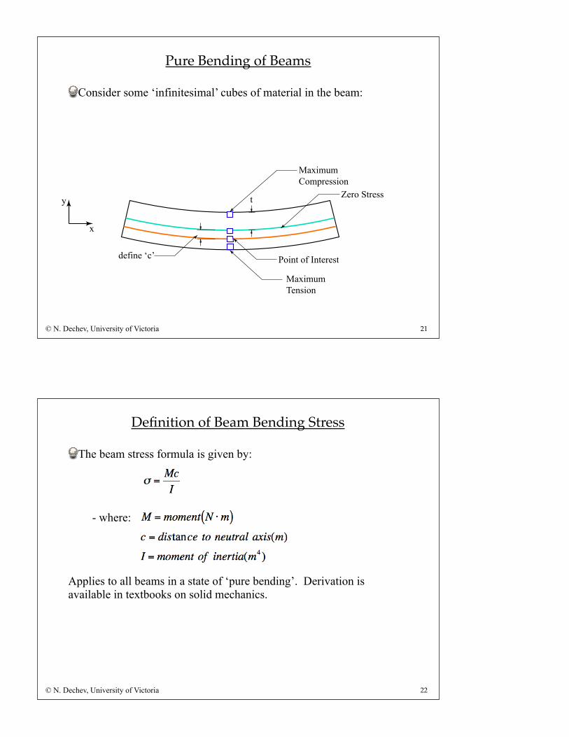
Pure Bending of Beams
© N. Dechev, University of Victoria
These are cases where a beam is subjected to a bending moment where we assume:
- Deflection as a result of bending is less than 5% of beam length
- All plane cross-sections of the beam before bending remain as straight planes after bending
y
x
+M +M
Tension
Neutral Axis
Compression
PlaneCross-Sections
21
Pure Bending of Beams
© N. Dechev, University of Victoria
Consider some ‘infinitesimal’ cubes of material in the beam:
y
x
t
Point of Interest
MaximumCompression
Zero Stress
MaximumTension
define ‘c’
22
Definition of Beam Bending Stress
© N. Dechev, University of Victoria
The beam stress formula is given by:
- where:
Applies to all beams in a state of ‘pure bending’. Derivation is available in textbooks on solid mechanics.
23
Moment of Inertia
© N. Dechev, University of Victoria
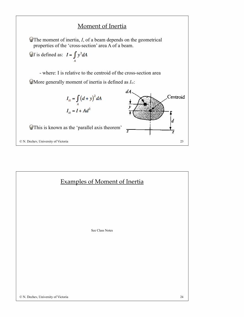
The moment of inertia, I, of a beam depends on the geometrical properties of the ‘cross-section’ area A of a beam.
I is defined as:
- where: I is relative to the centroid of the cross-section area
More generally moment of inertia is defined as Izz:
This is known as the ‘parallel axis theorem’
24
Examples of Moment of Inertia
© N. Dechev, University of Victoria
See Class Notes
A unique analytical solution exists for beam deflection, given by:
(a) beam geometry
(b) loading conditions
(c) boundary conditions
Generally, beam curvature ρ (rho), can be defined as:
Additionally, we can also define ρ as:
where ‘v’ is the beam deflection from the initial position. This approximation is valid when v < 5% of beam length.
25
Beam Deflection
© N. Dechev, University of Victoria
Therefore, we can develop the following differential equation, which can be solved for any beam, given the specific beam (a) geometry, (b) loading condition and (c) boundary condition:
It is beyond the scope of this course to solve these equations. For this course, we can use Appendix B in the textbook, which provides the deflections associated with this equation, for common ‘general cases’ found with MEMS beams.
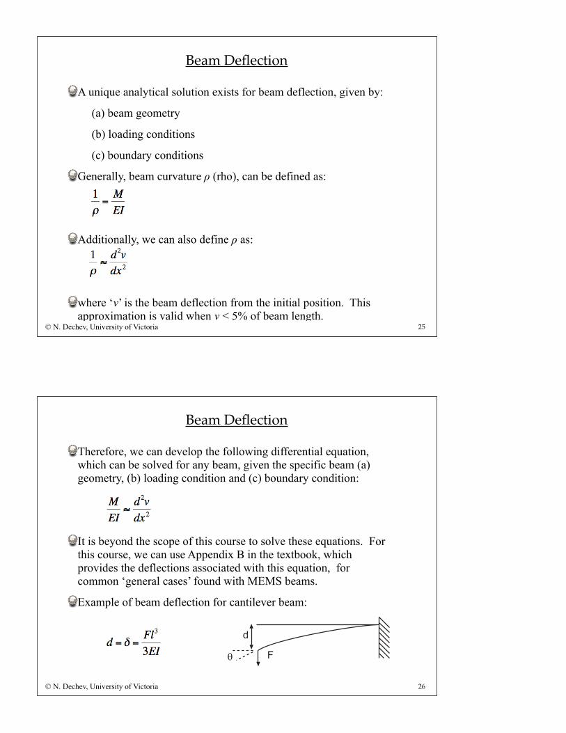
Example of beam deflection for cantilever beam:
26
Beam Deflection
© N. Dechev, University of Victoria
!
"
!
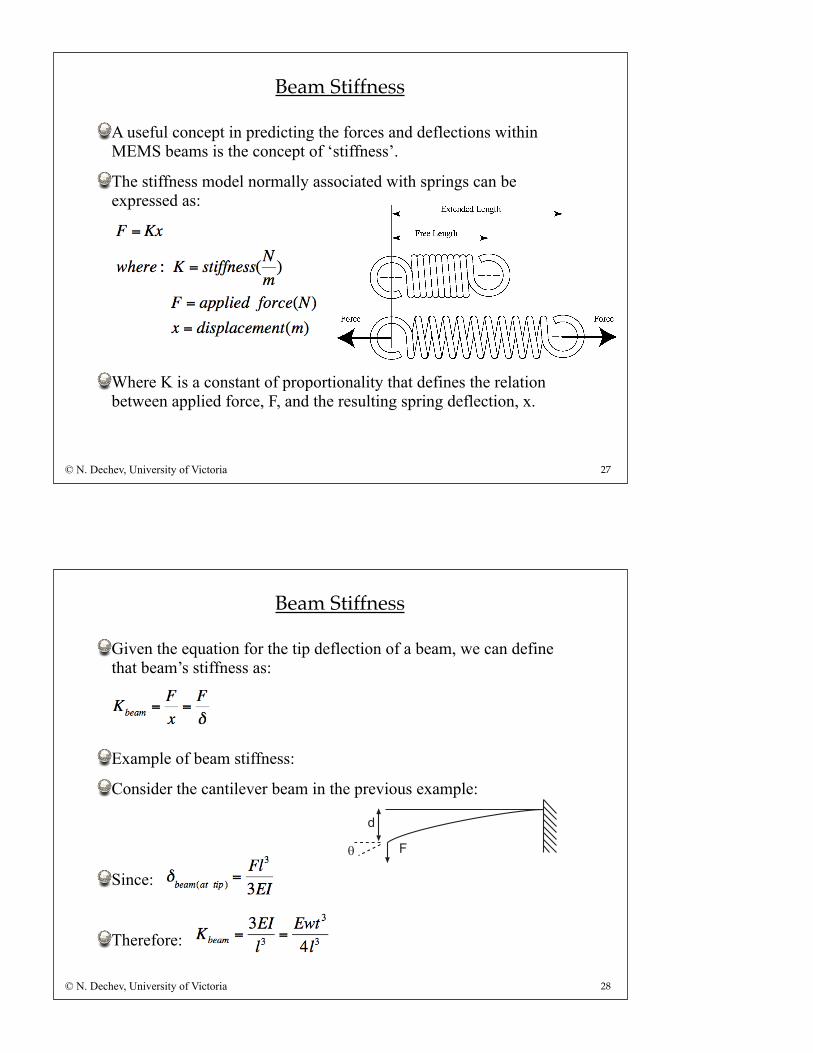
A useful concept in predicting the forces and deflections within MEMS beams is the concept of ‘stiffness’.
The stiffness model normally associated with springs can be expressed as:
Where K is a constant of proportionality that defines the relation between applied force, F, and the resulting spring deflection, x.
27
Beam Stiffness
© N. Dechev, University of Victoria
Given the equation for the tip deflection of a beam, we can define that beam’s stiffness as:
Example of beam stiffness:
Consider the cantilever beam in the previous example:
Since:
Therefore:
28
Beam Stiffness
© N. Dechev, University of Victoria
!
"
!
29
Calculation of Combined Mechanical Stiffnesses
© N. Dechev, University of Victoria
Computation of Stiffness for Springs in Series.
Computation of Stiffness for Springs in Parallel
See Class Notes
For some MEMS applications, the beams that allow the sensor or actuator to move undergo a twisting/torsional action.
In these cases, it is useful to review the basic formulas governing the torsion of beams, to determine:
(a) Maximum stress and it’s location
(b) Beam Stiffness
(c) Beam Deflection
30
Beam Torsion
© N. Dechev, University of Victoria
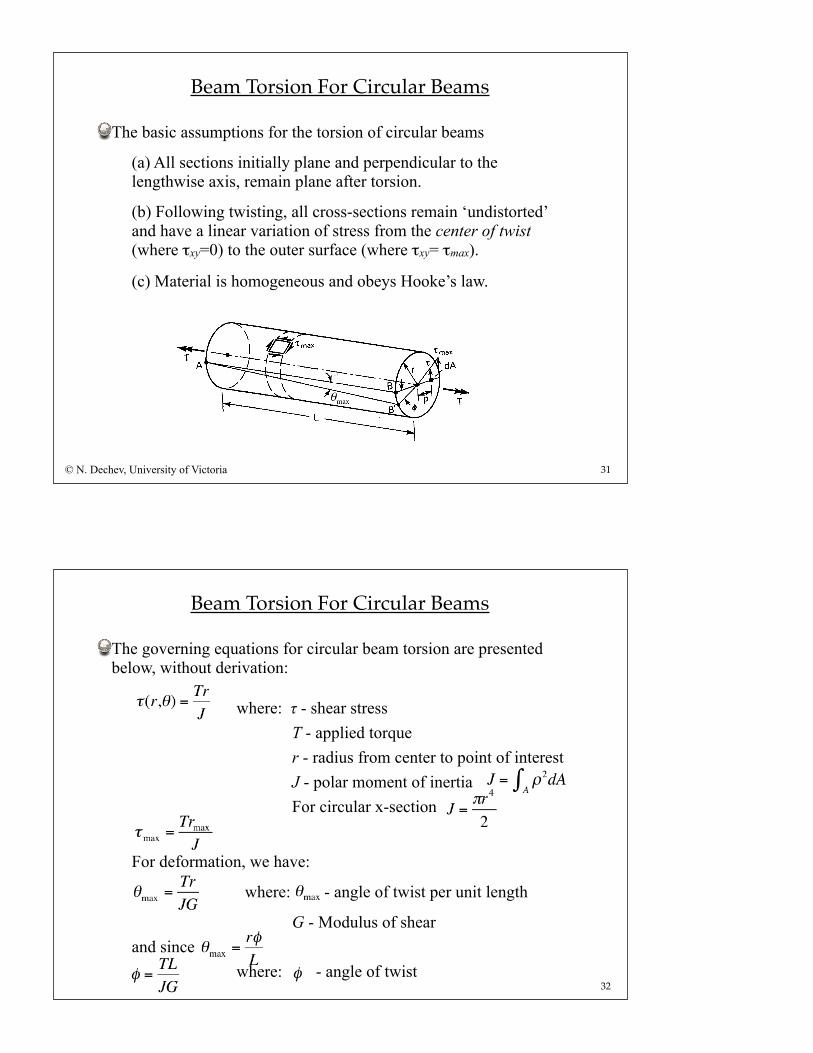
The basic assumptions for the torsion of circular beams
(a) All sections initially plane and perpendicular to the lengthwise axis, remain plane after torsion.
(b) Following twisting, all cross-sections remain ‘undistorted’ and have a linear variation of stress from the center of twist (where τxy=0) to the outer surface (where τxy= τmax).
(c) Material is homogeneous and obeys Hooke’s law.
31
Beam Torsion For Circular Beams
© N. Dechev, University of Victoria
The governing equations for circular beam torsion are presented below, without derivation:
where: τ - shear stress T - applied torque r - radius from center to point of interest J - polar moment of inertia For circular x-section
For deformation, we have:
where: - angle of twist per unit length
G - Modulus of shearand since
where: - angle of twist32
Beam Torsion For Circular Beams
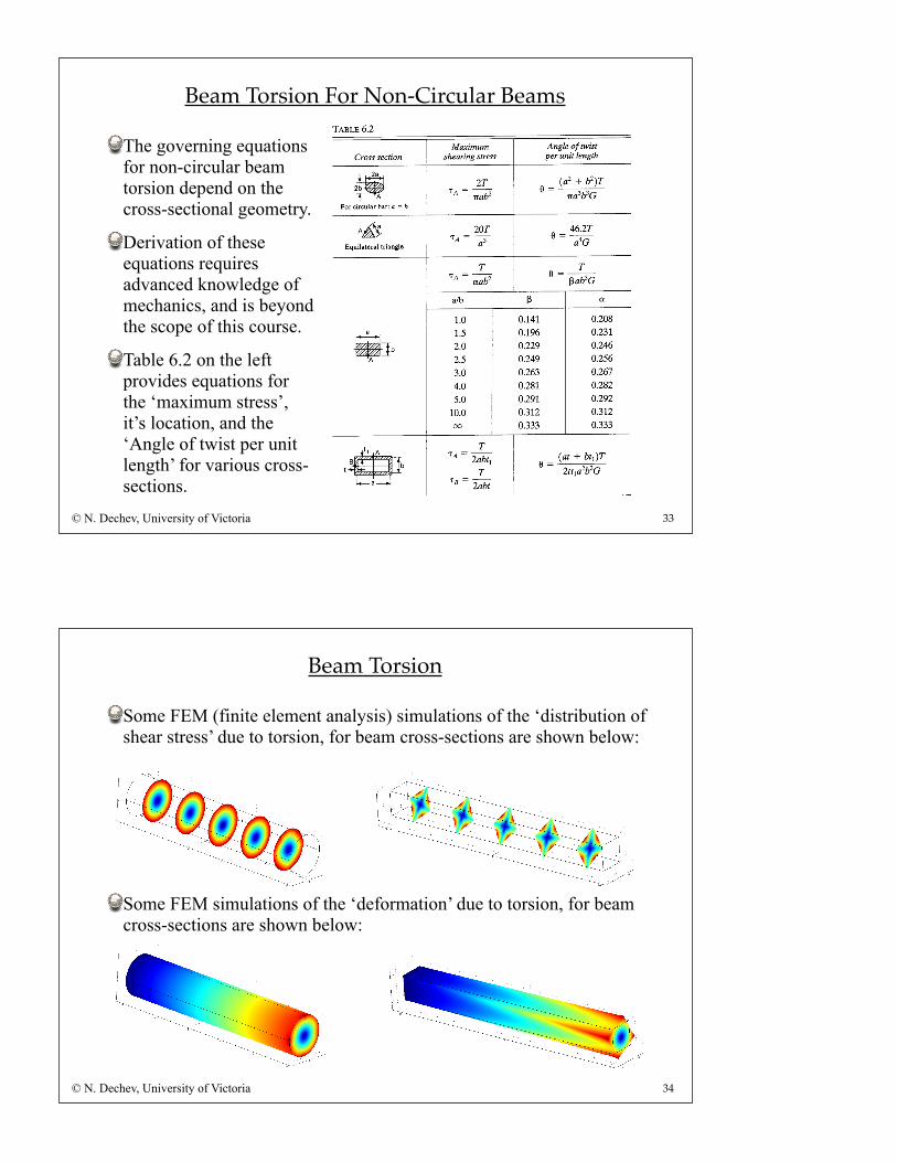
The governing equations for non-circular beam torsion depend on the cross-sectional geometry.
Derivation of these equations requires advanced knowledge of mechanics, and is beyond the scope of this course.
Table 6.2 on the left provides equations for the ‘maximum stress’, it’s location, and the ‘Angle of twist per unit length’ for various cross-sections.
Beam Torsion For Non-Circular Beams
33© N. Dechev, University of Victoria
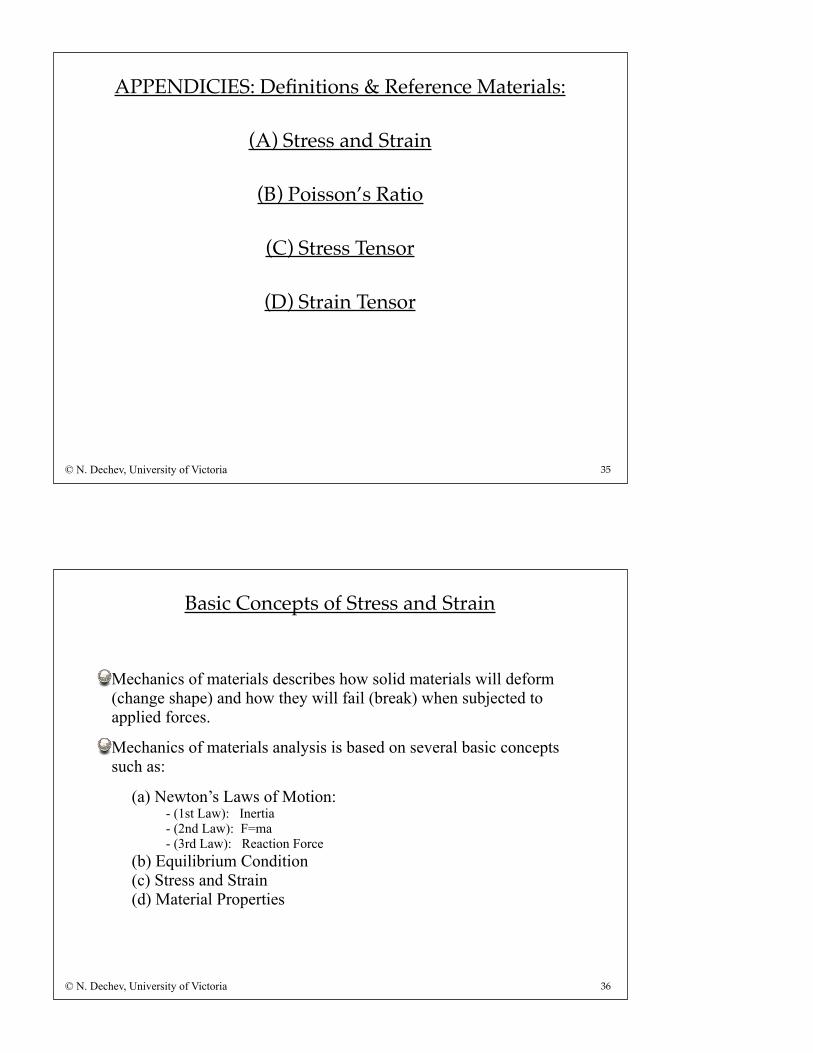
Some FEM (finite element analysis) simulations of the ‘distribution of shear stress’ due to torsion, for beam cross-sections are shown below:
Some FEM simulations of the ‘deformation’ due to torsion, for beam cross-sections are shown below:
Beam Torsion
34© N. Dechev, University of Victoria
35
APPENDICIES: Definitions & Reference Materials:
(A) Stress and Strain
(B) Poisson’s Ratio
(C) Stress Tensor
(D) Strain Tensor
© N. Dechev, University of Victoria
36
Basic Concepts of Stress and Strain
Mechanics of materials describes how solid materials will deform (change shape) and how they will fail (break) when subjected to applied forces.
Mechanics of materials analysis is based on several basic concepts such as:
(a) Newton’s Laws of Motion:- (1st Law): Inertia- (2nd Law): F=ma- (3rd Law): Reaction Force
(b) Equilibrium Condition(c) Stress and Strain(d) Material Properties
© N. Dechev, University of Victoria
37
Static Equilibrium of Bodies
The static equilibrium condition states that all forces and moments applied to a body are ‘balanced’ such that there is no net acceleration of the body.
More specifically:
-The vector summation of all forces acting on a body must be equal to zero, and...
-The sum of all moments acting must be equal to zero.
Therefore, for a 3D body in space:
- these six equations must be satisfied for the body to be in ‘static equilibrium’
© N. Dechev, University of Victoria
38
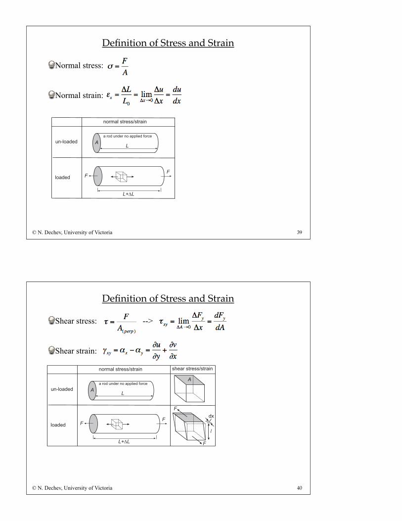
Definition of Stress and Strain
Stress is a measure of:
Normal stress is defined as:
Strain is a measure of:
Normal strain is defined as:
© N. Dechev, University of Victoria
Applied force on a materialArea over which that force is applied
Elongation of a material due to an applied forceThe original length of the material
(*Note: the textbook denotes strain as “s”)
39
Definition of Stress and Strain
Normal stress:
Normal strain:
© N. Dechev, University of Victoria
!
"
!
#$!#
#
!"#$%"&'%(#"'$"!))*+(%",$#-("
!
&'.*$!%(%
*$!%(%
'$#/!*"01#(00201#!+' 03(!#"01#(00201#!+'
%4
!
!
40
Definition of Stress and Strain
Shear stress: -->
Shear strain:
© N. Dechev, University of Victoria
!
"
!
#$!#
#
!"#$%"&'%(#"'$"!))*+(%",$#-("
!
&'.*$!%(%
*$!%(%
'$#/!*"01#(00201#!+' 03(!#"01#(00201#!+'
%4
!
!
41
Relation Between Stress and Strain
Hooke’s Law defines the relationship between stress and strain, where:
The above equation is a simple linear model for the 1-D analysis of materials operating in the elastic region of behavior.
If we require a 3D analysis of materials, we must use a more advanced matrix relationship between stress and strain, known as Generalized Hooke’s Law.
© N. Dechev, University of Victoria
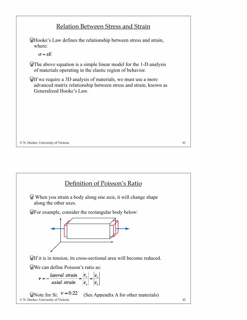
When you strain a body along one axis, it will change shape along the other axes.
For example, consider the rectangular body below:
If it is in tension, its cross-sectional area will become reduced.
We can define Poisson’s ratio as:
Note for Si: (See Appendix A for other materials)42
Definition of Poisson’s Ratio
© N. Dechev, University of Victoria
43
Definition of Stress Tensor
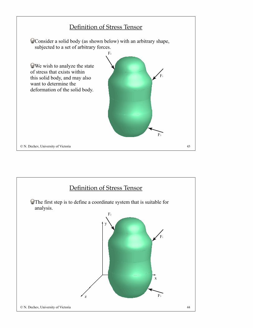
Consider a solid body (as shown below) with an arbitrary shape, subjected to a set of arbitrary forces.
We wish to analyze the stateof stress that exists withinthis solid body, and may alsowant to determine the deformation of the solid body.
© N. Dechev, University of Victoria
F1
F3
F2
y
x
z
44
Definition of Stress Tensor
The first step is to define a coordinate system that is suitable for analysis.
© N. Dechev, University of Victoria
F1
F3
F2
y
x
z
45
Definition of Stress Tensor
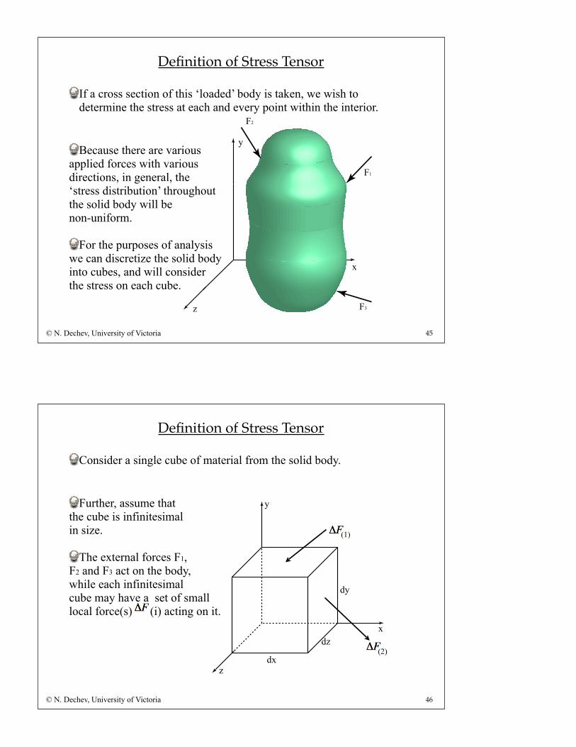
If a cross section of this ‘loaded’ body is taken, we wish to determine the stress at each and every point within the interior.
Because there are variousapplied forces with variousdirections, in general, the‘stress distribution’ throughout the solid body will be non-uniform.
For the purposes of analysiswe can discretize the solid bodyinto cubes, and will considerthe stress on each cube.
© N. Dechev, University of Victoria
F3
F1
F2
Consider a single cube of material from the solid body.
Further, assume thatthe cube is infinitesimalin size.
The external forces F1,F2 and F3 act on the body,while each infinitesimal cube may have a set of smalllocal force(s) (i) acting on it.
46
Definition of Stress Tensor
© N. Dechev, University of Victoria
y
x
z
dy
dx
dz
(1)
(2)
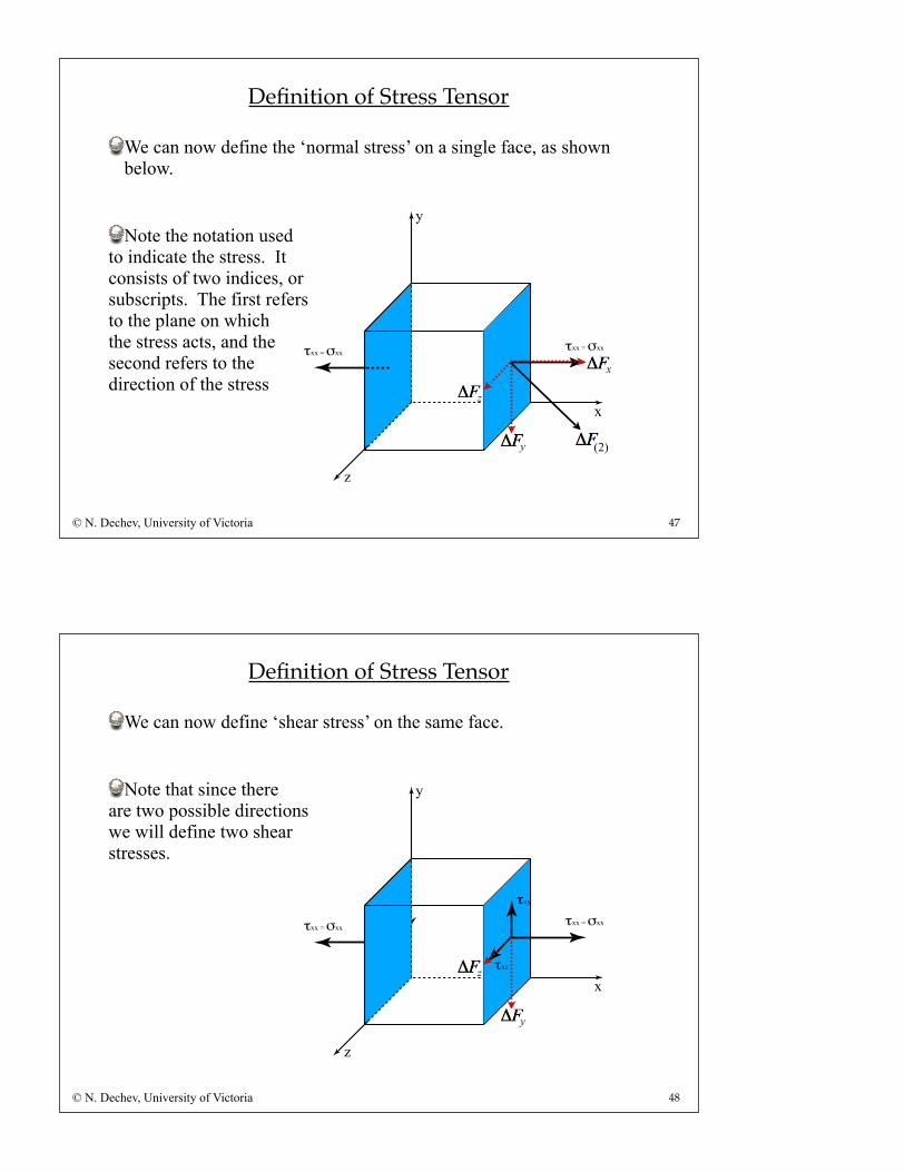
We can now define the ‘normal stress’ on a single face, as shown below.
Note the notation usedto indicate the stress. Itconsists of two indices, orsubscripts. The first refersto the plane on whichthe stress acts, and thesecond refers to thedirection of the stress
47
Definition of Stress Tensor
© N. Dechev, University of Victoria
y
x
z
τxx = σxxτxx = σxx
x
y
z
(2)
τxx = σxxτxz
τxy
We can now define ‘shear stress’ on the same face.
Note that since thereare two possible directionswe will define two shearstresses.
48
Definition of Stress Tensor
© N. Dechev, University of Victoria
y
x
z
τxx = σxx
τxy
τxz
y
z
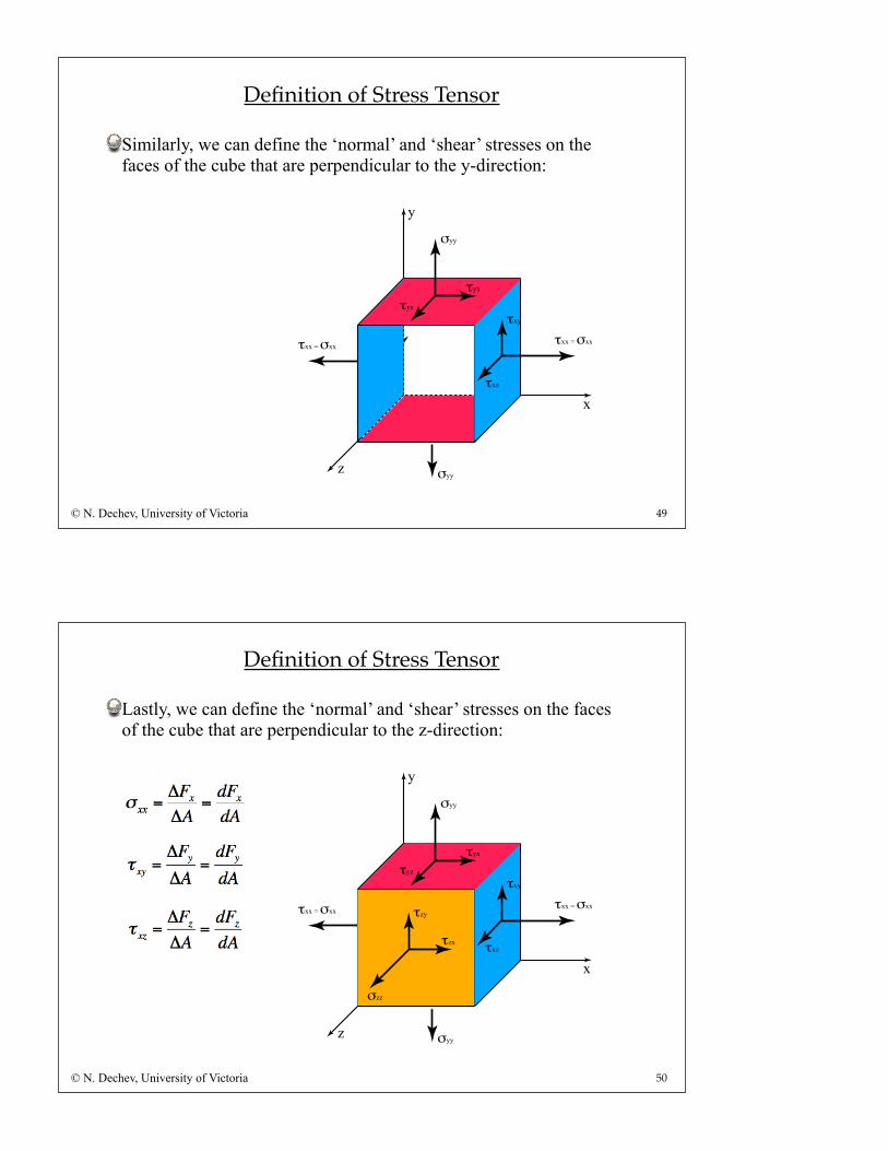
Similarly, we can define the ‘normal’ and ‘shear’ stresses on the faces of the cube that are perpendicular to the y-direction:
τxx = σxxτxz
τxy
σyy
τyzτyx
49
Definition of Stress Tensor
© N. Dechev, University of Victoria
y
x
z
τxx = σxx
τxy
τxz
σyy
τyzτyx
Lastly, we can define the ‘normal’ and ‘shear’ stresses on the faces of the cube that are perpendicular to the z-direction:
σzz
τxx = σxxτxz
τxy
σyy
τyzτyx
50
Definition of Stress Tensor
© N. Dechev, University of Victoria
y
x
z
τxx = σxx
τxy
τxz
σyy
τyzτyx
σzz
τzy
τzx
51
Definition of Stress Tensor
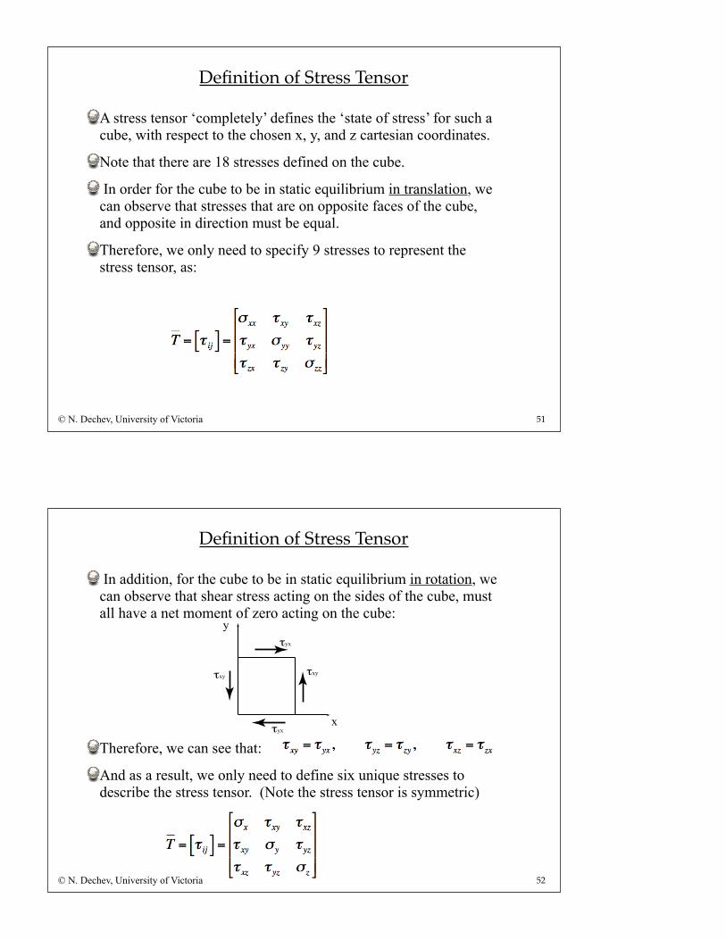
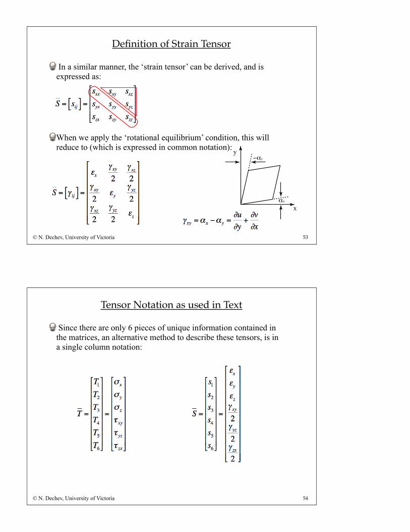
A stress tensor ‘completely’ defines the ‘state of stress’ for such a cube, with respect to the chosen x, y, and z cartesian coordinates.
Note that there are 18 stresses defined on the cube.
In order for the cube to be in static equilibrium in translation, we can observe that stresses that are on opposite faces of the cube, and opposite in direction must be equal.
Therefore, we only need to specify 9 stresses to represent the stress tensor, as:
© N. Dechev, University of Victoria
52
Definition of Stress Tensor
In addition, for the cube to be in static equilibrium in rotation, we can observe that shear stress acting on the sides of the cube, must all have a net moment of zero acting on the cube:
Therefore, we can see that:
And as a result, we only need to define six unique stresses to describe the stress tensor. (Note the stress tensor is symmetric)
© N. Dechev, University of Victoria
τxyτxy
τyx
τyx
y
x
53
Definition of Strain Tensor
In a similar manner, the ‘strain tensor’ can be derived, and is expressed as:
When we apply the ‘rotational equilibrium’ condition, this will reduce to (which is expressed in common notation):
© N. Dechev, University of Victoria
−αy
αx
y
x
54
Tensor Notation as used in Text
Since there are only 6 pieces of unique information contained in the matrices, an alternative method to describe these tensors, is in a single column notation:
© N. Dechev, University of Victoria
55
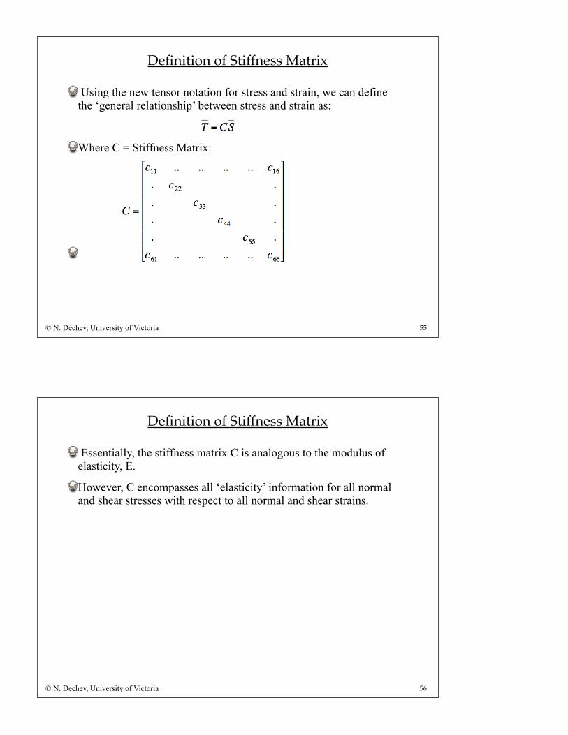
Definition of Stiffness Matrix
Using the new tensor notation for stress and strain, we can define the ‘general relationship’ between stress and strain as:
Where C = Stiffness Matrix:
© N. Dechev, University of Victoria
56
Definition of Stiffness Matrix
Essentially, the stiffness matrix C is analogous to the modulus of elasticity, E.
However, C encompasses all ‘elasticity’ information for all normal and shear stresses with respect to all normal and shear strains.
© N. Dechev, University of Victoria