Embed Size (px)
Citation preview
1
RODS: THERMAL STRESS AND STRESS CONCENTRATION
Statically Indeterminate Axially Loaded Members
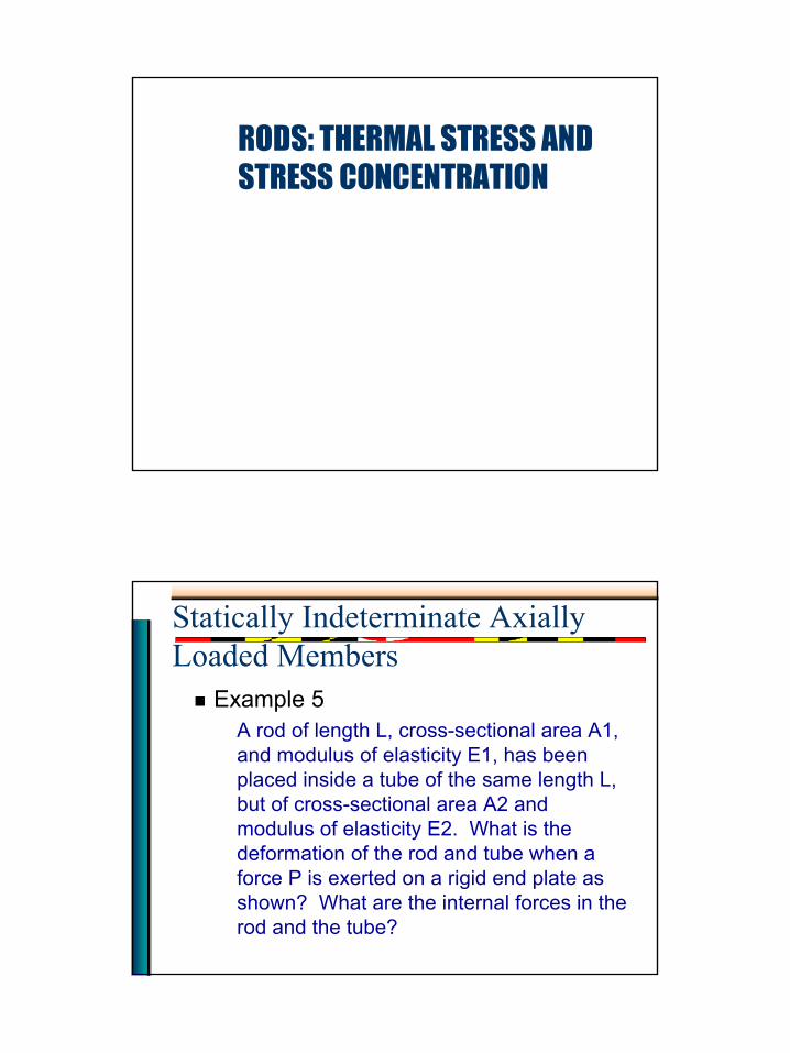
Example 5A rod of length L, cross-sectional area A1, and modulus of elasticity E1, has been placed inside a tube of the same length L, but of cross-sectional area A2 and modulus of elasticity E2. What is the deformation of the rod and tube when a force P is exerted on a rigid end plate as shown? What are the internal forces in the rod and the tube?
2
Statically Indeterminate Axially Loaded Members
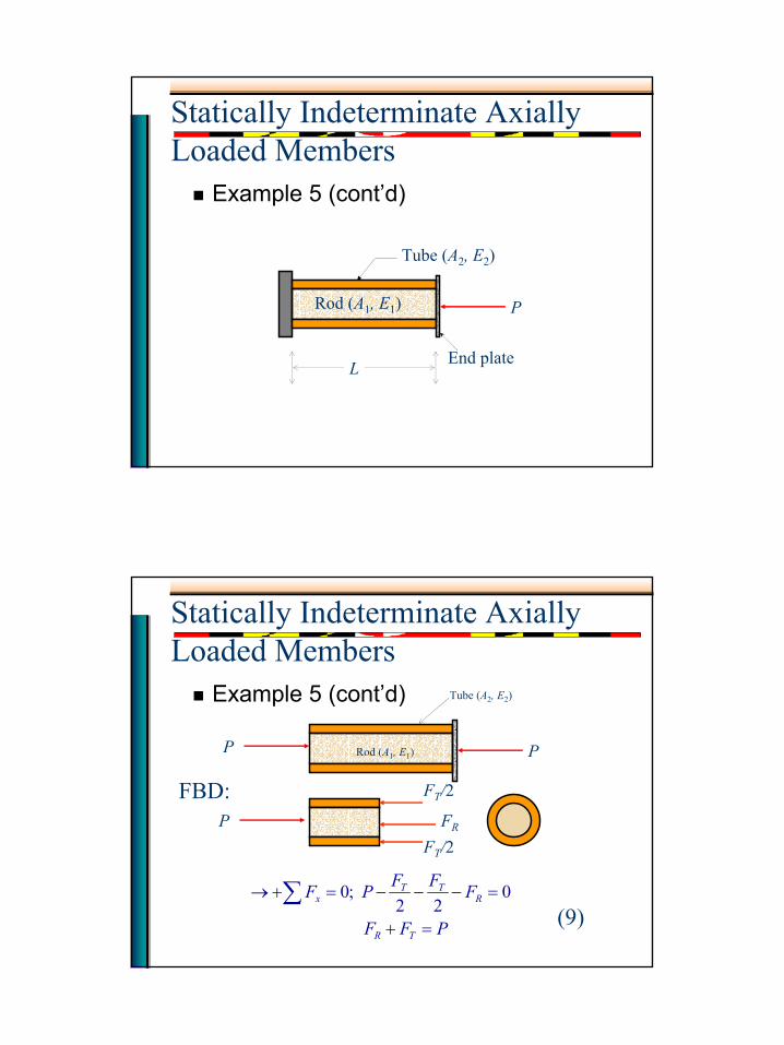
Example 5 (cont’d)
End plate
P
Tube (A2, E2)
Rod (A1, E1)
L
Statically Indeterminate Axially Loaded Members
Example 5 (cont’d)
PP
P
FT/2
FT/2FR
Tube (A2, E2)
Rod (A1, E1)
PFF
FFFPF
TR
RTT
x
=+
=−−−=+→ ∑
022
;0(9)
FBD:
3
Statically Indeterminate Axially Loaded Members
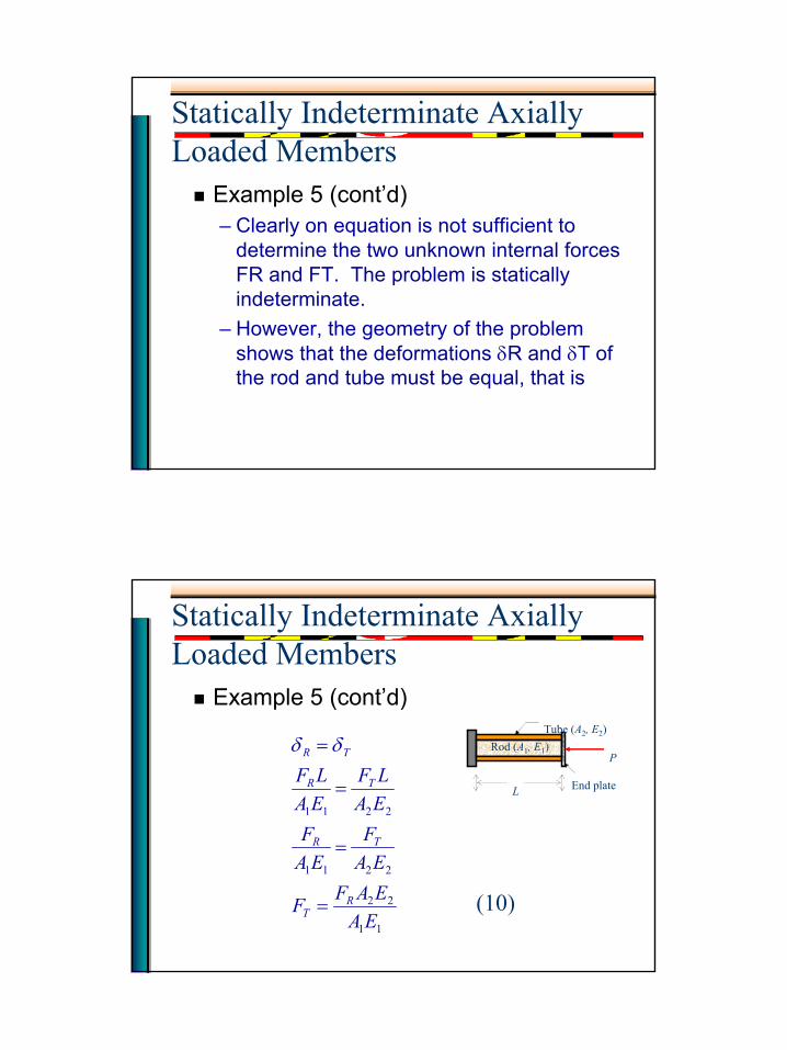
Example 5 (cont’d)– Clearly on equation is not sufficient to
determine the two unknown internal forces FR and FT. The problem is statically indeterminate.
– However, the geometry of the problem shows that the deformations δR and δT of the rod and tube must be equal, that is
Statically Indeterminate Axially Loaded Members
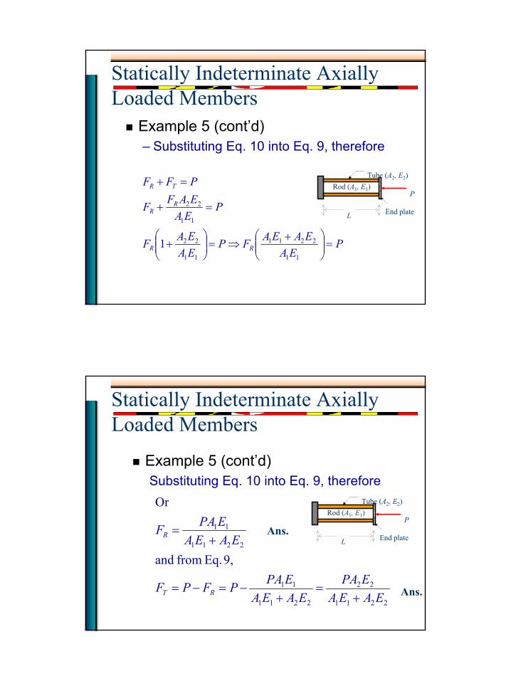
Example 5 (cont’d)
11
22
2211
2211
EAEAFF
EAF
EAF
EALF
EALF
RT
TR
TR
TR
=
=
=
= δδ
End plate
P
Tube (A2, E2)Rod (A1, E1)
L
(10)
4
Statically Indeterminate Axially Loaded Members
Example 5 (cont’d)– Substituting Eq. 10 into Eq. 9, therefore
End plate
P
Tube (A2, E2)Rod (A1, E1)
L
PEA
EAEAFPEAEAF
PEA
EAFF
PFF
RR
RR
TR
=
+⇒=
+
=+
=+
11
2211
11
22
11
22
1
Statically Indeterminate Axially Loaded Members
Example 5 (cont’d)Substituting Eq. 10 into Eq. 9, therefore
End plate
P
Tube (A2, E2)Rod (A2, E2)
L
2211
22
2211
11
2211
11
9, Eq. from and
Or
EAEAEPA
EAEAEPAPFPF
EAEAEPAF
RT
R
+=
+−=−=
+= Ans.
Ans.
End plate
P
Tube (A2, E2)Rod (A1, E1)
L

5
Statically Indeterminate Axially Loaded Members
Example 6A very stiff bar of negligible weight is suspended horizontally by two vertical rods as shown. One of the rods is of steel, and is ½-in in diameter and 4 ft long; the other is of brass and is 7/8-in in diameter and 8 ft long. If a vertical load of 6000 lb is applied to the bar, where must be placed in order that the bar will remain horizontal? Take Es = 30×106 psi and Eb = 14×106.
Statically Indeterminate Axially Loaded Members
Example 6 (cont’d)• Also find the stresses in the brass and steel rods.
8 ft Brass Steel
10 ft
4 ftx
6000 lb
6
Statically Indeterminate Axially Loaded Members
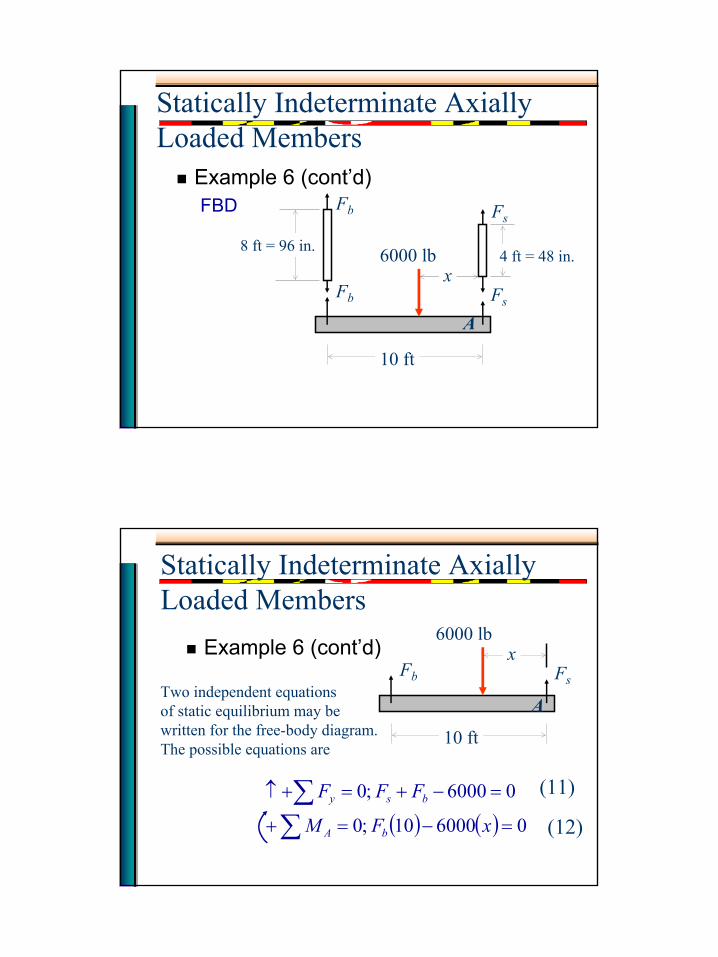
Example 6 (cont’d)FBD
6000 lb
AFsFb
Fb Fs
10 ft
x4 ft = 48 in.
8 ft = 96 in.
Statically Indeterminate Axially Loaded Members
Example 6 (cont’d)6000 lb
FsFb
10 ft
x
Two independent equationsof static equilibrium may bewritten for the free-body diagram.The possible equations are
( ) ( )∑∑
=−=+
=−+=+↑
0600010 ;0
06000 ;0
xFM
FFF
bA
bsy(11)
(12)
A
7
Statically Indeterminate Axially Loaded Members
Example 6 (cont’d)• Since no more independent equations of
equilibrium can be written and there are three unknown quantities, the structure is statically indeterminate.
• One additional independent equation is needed. The problem requires that the bar remain horizontal. Therefore, the rods must undergo equal elongations, that is
bs δδ = (13)
Statically Indeterminate Axially Loaded Members
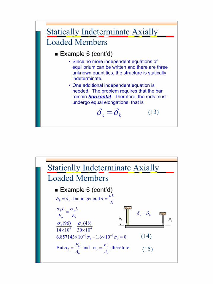
Example 6 (cont’d)
bδ bδbs δδ =
therefore, and But
0106.110857143.61030
)48(1014
)96(
generalin but ,
66
66
s
ss
b
bb
sb
sb
s
s
b
b
sb
AF
AF
EL
EL
EσL
==
=×−××
=×
=
==
−−
σσ
σσ
σσ
σσ
δδδ
(14)
(15)
8
Statically Indeterminate Axially Loaded Members
Example 6 (cont’d)
( )
( ) 22
22
66
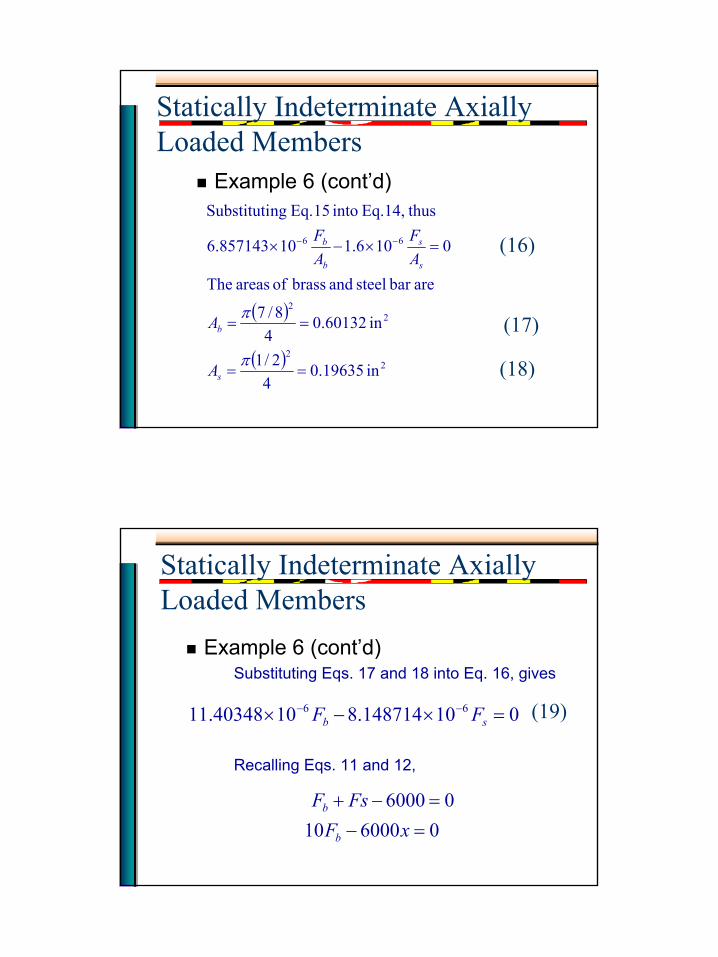
in 19635.04
2/1
in 60132.04
8/7
arebar steel and brass of areas The
0106.110857143.6
thusEq.14, into 15 Eq. ngSubstituti
==
==
=×−× −−
π
π
s
b
s
s
b
b
A
A
AF
AF (16)
(17)
(18)
Statically Indeterminate Axially Loaded Members
Example 6 (cont’d)Substituting Eqs. 17 and 18 into Eq. 16, gives
Recalling Eqs. 11 and 12,
010148714.81040348.11 66 =×−× −−sb FF (19)
060001006000
=−=−+
xFFsF
b
b
9
Statically Indeterminate Axially Loaded Members
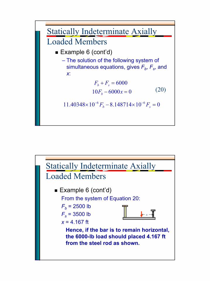
Example 6 (cont’d)– The solution of the following system of
simultaneous equations, gives Fb, Fs, and x:
06000106000
=−=+
xFFF
b
sb(20)
010148714.81040348.11 66 =×−× −−sb FF
Statically Indeterminate Axially Loaded Members
Example 6 (cont’d)From the system of Equation 20:Fb = 2500 lbFs = 3500 lbx = 4.167 ft
Hence, if the bar is to remain horizontal, the 6000-lb load should placed 4.167 ft from the steel rod as shown.
x
10
Statically Indeterminate Axially Loaded Members
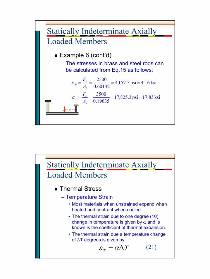
Example 6 (cont’d)The stresses in brass and steel rods can be calculated from Eq.15 as follows:
ksi 17.83 psi 3.825,1719635.03500
ksi 4.16 psi 5.157,460132.02500
====
====
s
ss
b
bb
AFAF
σ
σ
x
Statically Indeterminate Axially Loaded Members
Thermal Stress– Temperature Strain
• Most materials when unstrained expand when heated and contract when cooled.
• The thermal strain due to one degree (10) change in temperature is given by α and is known is the coefficient of thermal expansion.
• The thermal strain due a temperature change of ∆T degrees is given by
TT ∆=αε (21)
11
Statically Indeterminate Axially Loaded Members
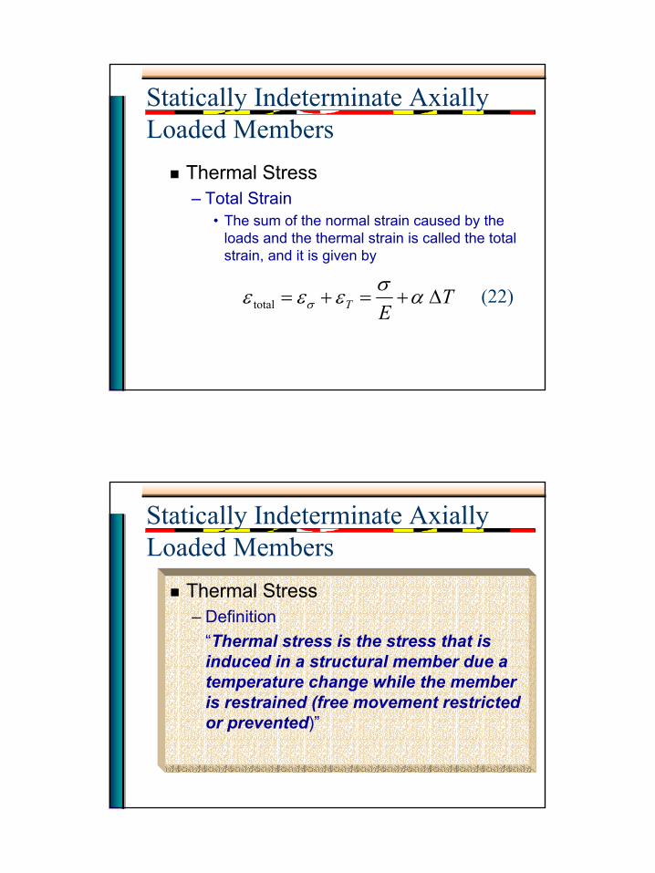
Thermal Stress– Total Strain
• The sum of the normal strain caused by the loads and the thermal strain is called the total strain, and it is given by
TET ∆+=+= total ασεεε σ (22)
Statically Indeterminate Axially Loaded Members
Thermal Stress– Definition
“Thermal stress is the stress that is induced in a structural member due a temperature change while the member is restrained (free movement restricted or prevented)”
12
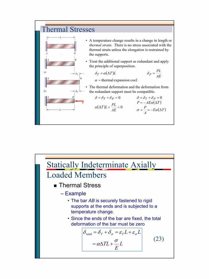
ENES 220 ©AssakkafThermal Stresses• A temperature change results in a change in length or
thermal strain. There is no stress associated with the thermal strain unless the elongation is restrained by the supports.
( )coef.expansion thermal=
=∆=
α
δαδAEPLLT PT
• Treat the additional support as redundant and apply the principle of superposition.
( ) 0
0
=+∆
=+=
AEPLLT
PT
α
δδδ
• The thermal deformation and the deformation from the redundant support must be compatible.
( )( )TE
AP
TAEPPT
∆−==
∆−==+=
ασ
αδδδ 0
Statically Indeterminate Axially Loaded Members
Thermal Stress– Example
• The bar AB is securely fastened to rigid supports at the ends and is subjected to a temperature change.
• Since the ends of the bar are fixed, the total deformation of the bar must be zero
LE
TL
LLTT
σα
εεδδδ σσ
+∆=
+=+=
total
(23)
13
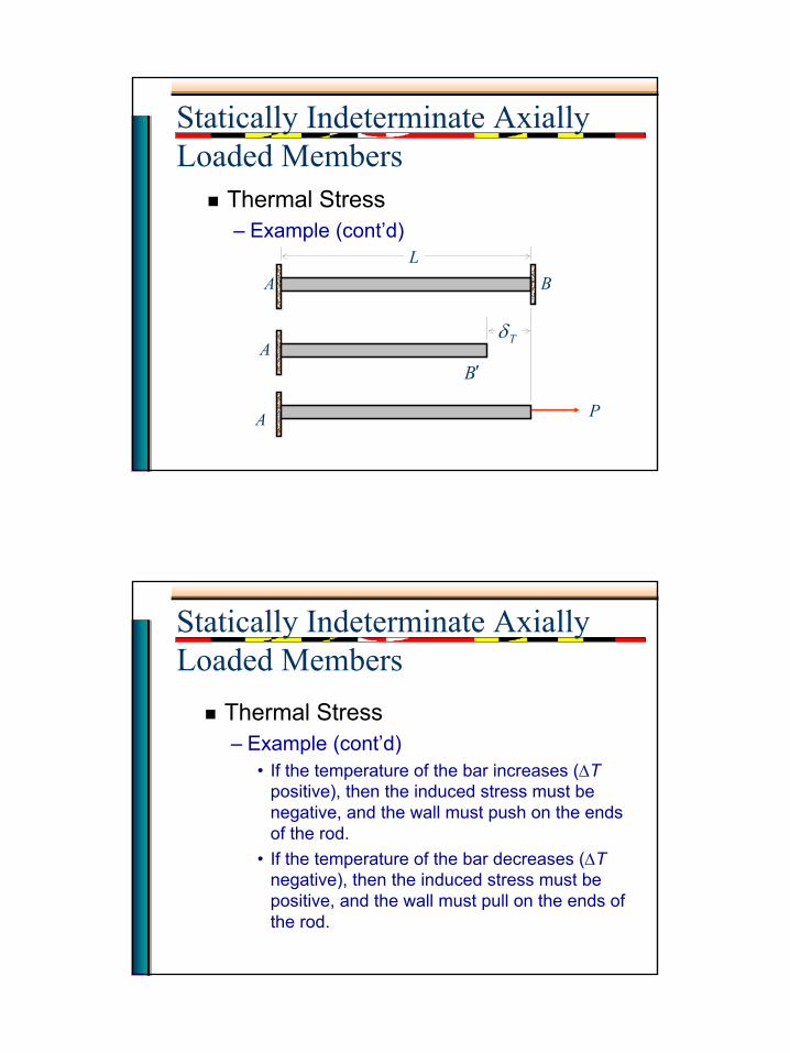
Statically Indeterminate Axially Loaded Members
Thermal Stress– Example (cont’d)
A BL
A
A
B′
Tδ
P
Statically Indeterminate Axially Loaded Members
Thermal Stress– Example (cont’d)
• If the temperature of the bar increases (∆Tpositive), then the induced stress must be negative, and the wall must push on the ends of the rod.
• If the temperature of the bar decreases (∆Tnegative), then the induced stress must be positive, and the wall must pull on the ends of the rod.
14
Statically Indeterminate Axially Loaded Members
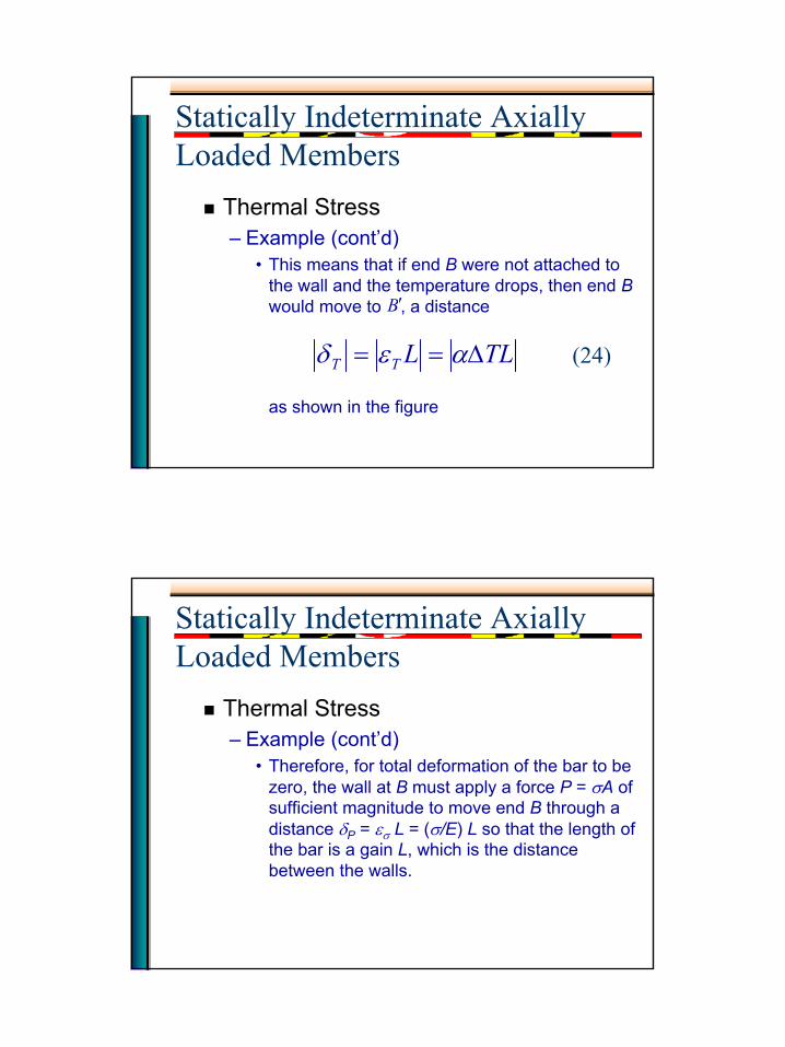
Thermal Stress– Example (cont’d)
• This means that if end B were not attached to the wall and the temperature drops, then end Bwould move to , a distance
as shown in the figure
B′
TLLTT ∆== αεδ (24)
Statically Indeterminate Axially Loaded Members
Thermal Stress– Example (cont’d)
• Therefore, for total deformation of the bar to be zero, the wall at B must apply a force P = σA of sufficient magnitude to move end B through a distance δP = εσ L = (σ/E) L so that the length of the bar is a gain L, which is the distance between the walls.
15
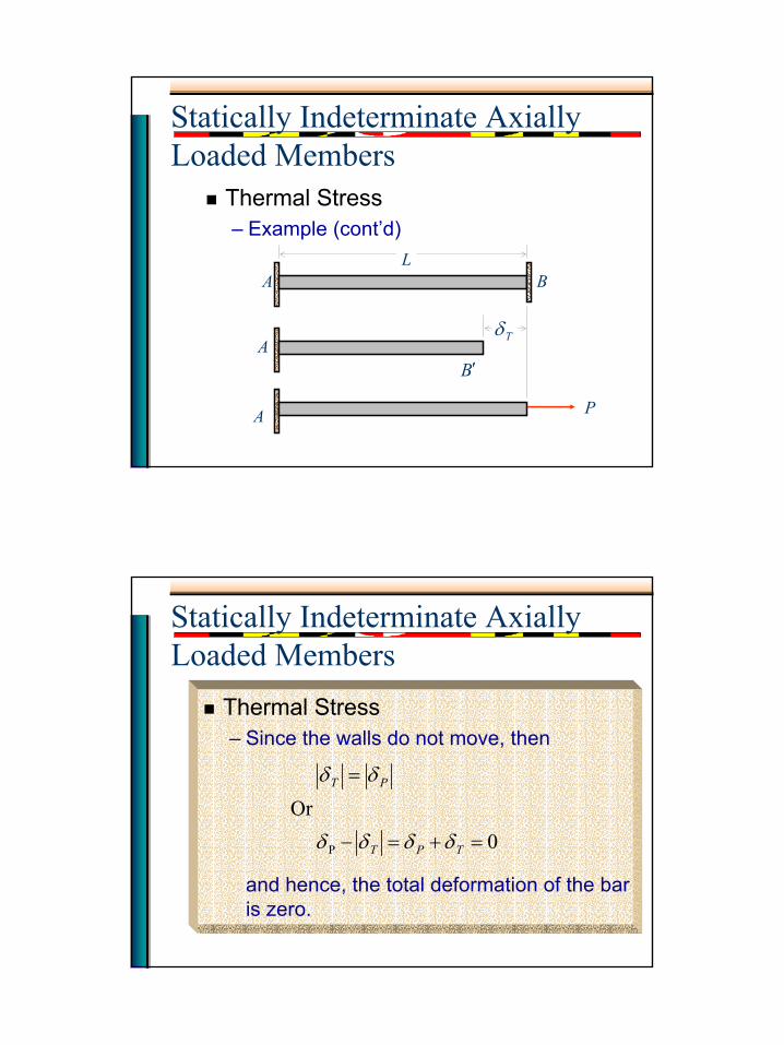
Statically Indeterminate Axially Loaded Members
Thermal Stress– Example (cont’d)
A BL
A
A
B′
Tδ
P
Statically Indeterminate Axially Loaded Members
Thermal Stress– Since the walls do not move, then
and hence, the total deformation of the bar is zero.
0 Or
P =+=−
=
TPT
PT
δδδδ
δδ
16
Statically Indeterminate Axially Loaded Members
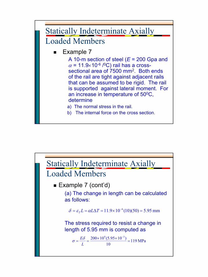
Example 7A 10-m section of steel (E = 200 Gpa and α = 11.9×10⁻⁶ /0C) rail has a cross-sectional area of 7500 mm2. Both ends of the rail are tight against adjacent rails that can be assumed to be rigid. The rail is supported against lateral moment. For an increase in temperature of 500C, determinea) The normal stress in the rail.b) The internal force on the cross section.
Statically Indeterminate Axially Loaded Members
Example 7 (cont’d)(a) The change in length can be calculated as follows:
The stress required to resist a change in length of 5.95 mm is computed as
mm 95.5)50)(10(109.11 6 =×=∆== −TLLT αεδ
MPa 11910
)1095.5(10200 39
=××
==−
LEδσ
17
Statically Indeterminate Axially Loaded Members
Example 7 (cont’d)(b) The internal force on a cross section of the rail is computed as follows:
kN 893 N105.892)107500(10119 366
=×=××== −AF σ
Statically Indeterminate Axially Loaded Members
General Notes on Thermal Stress and Thermal Deformation– The results that was discussed earlier
apply only in the case of a homogenousrod (or bar) of uniform cross section.
– Any other problem involving a restrained member undergoing a change in temperature must be analyzed on its own merits.
18
Statically Indeterminate Axially Loaded Members
General Notes on Thermal Stress and Thermal Deformation– However, the same general approach may
be used, that is, we may consider separately the deformation due to temperature change and the deformation due to the redundant reaction and superimpose the solutions obtained.
Statically Indeterminate Axially Loaded Members
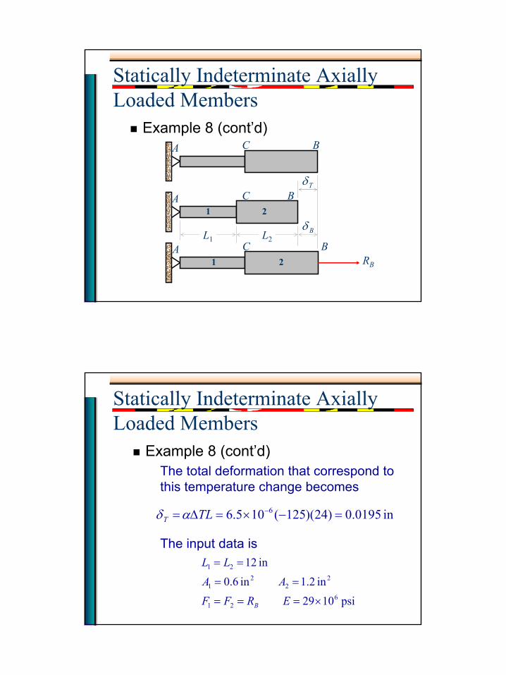
Example 8Determine the values of the stress in portion AC and CB of the steel bar shown when a the temperature of the bar is –500F, knowing that a close fit exists at both of the rigid supports when the temperature is +700F. Use E = 29×106 psi andα = 6.5 ×10⁻⁶/0F for steel.
19
Statically Indeterminate Axially Loaded Members
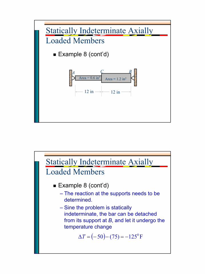
Example 8 (cont’d)
A C BArea = 1.2 in2Area = 0.6 in2
12 in 12 in
Statically Indeterminate Axially Loaded Members
Example 8 (cont’d)– The reaction at the supports needs to be
determined.– Sine the problem is statically
indeterminate, the bar can be detached from its support at B, and let it undergo the temperature change
( ) F125)75(50 0−=−−=∆T
20
Statically Indeterminate Axially Loaded Members
Example 8 (cont’d)A C B
A C B
A C BL1 L2
Tδ
Bδ
RB
1 2
1 2
Statically Indeterminate Axially Loaded Members
Example 8 (cont’d)The total deformation that correspond to this temperature change becomes
The input data is
in 0195.0)24)(125(105.6 6 =−×=∆= −TLT αδ
psi 1029
in 2.1 in 6.0
in 12
621
22
21
21
×===
==
==
ERFF
AA
LL
B
21
Statically Indeterminate Axially Loaded Members
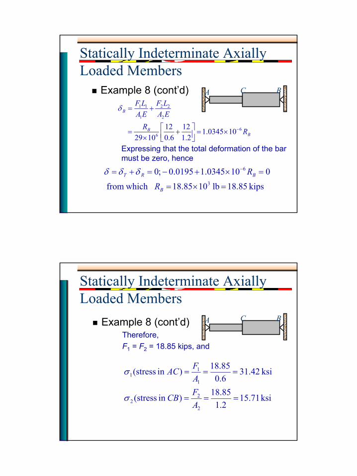
Example 8 (cont’d)
Expressing that the total deformation of the bar must be zero, hence
BB
B
RREALF
EALF
66
2
22
1
11
100345.12.1
126.0
121029
−×=
+
×=
+=δ
kips 85.18 lb 1085.18 which from
0100345.10195.0 ;03
6
=×=
=×+−=+= −
B
BRT
R
Rδδδ
A C B
Statically Indeterminate Axially Loaded Members
Example 8 (cont’d)Therefore,F1 = F2 = 18.85 kips, and
ksi 71.152.185.18)in (stress
ksi 42.316.085.18)in (stress
2
22
1
11
===
===
AFCB
AFAC
σ
σ
A C B
22
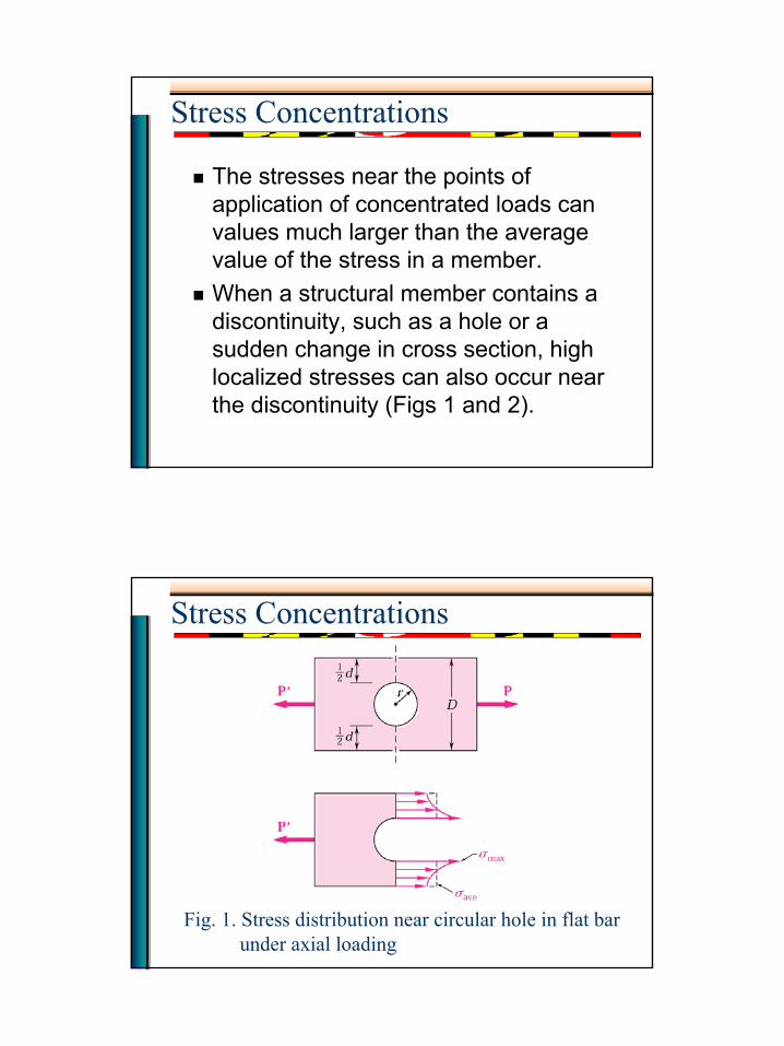
Stress Concentrations
The stresses near the points of application of concentrated loads can values much larger than the average value of the stress in a member.When a structural member contains a discontinuity, such as a hole or a sudden change in cross section, high localized stresses can also occur near the discontinuity (Figs 1 and 2).
Stress Concentrations
Fig. 1. Stress distribution near circular hole in flat barunder axial loading
23
Stress Concentrations
Fig. 2. Stress distribution near fillets in flat bar underaxial loading
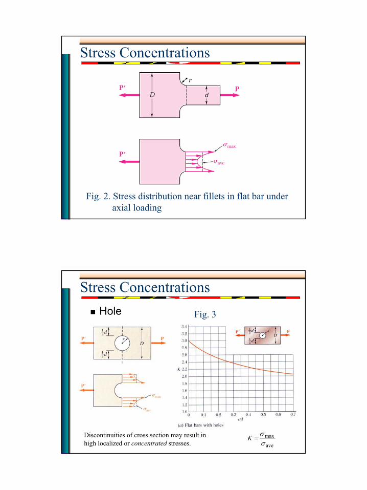
Stress ConcentrationsHole
Discontinuities of cross section may result in high localized or concentrated stresses. ave
maxσσ
=K
Fig. 3
24
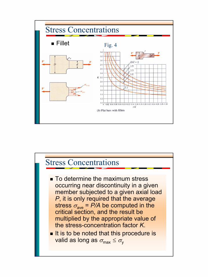
Stress ConcentrationsFillet Fig. 4
Stress Concentrations
To determine the maximum stress occurring near discontinuity in a given member subjected to a given axial load P, it is only required that the average stress σave = P/A be computed in the critical section, and the result be multiplied by the appropriate value of the stress-concentration factor K.It is to be noted that this procedure is valid as long as σmax ≤ σy
25
Stress Concentrations
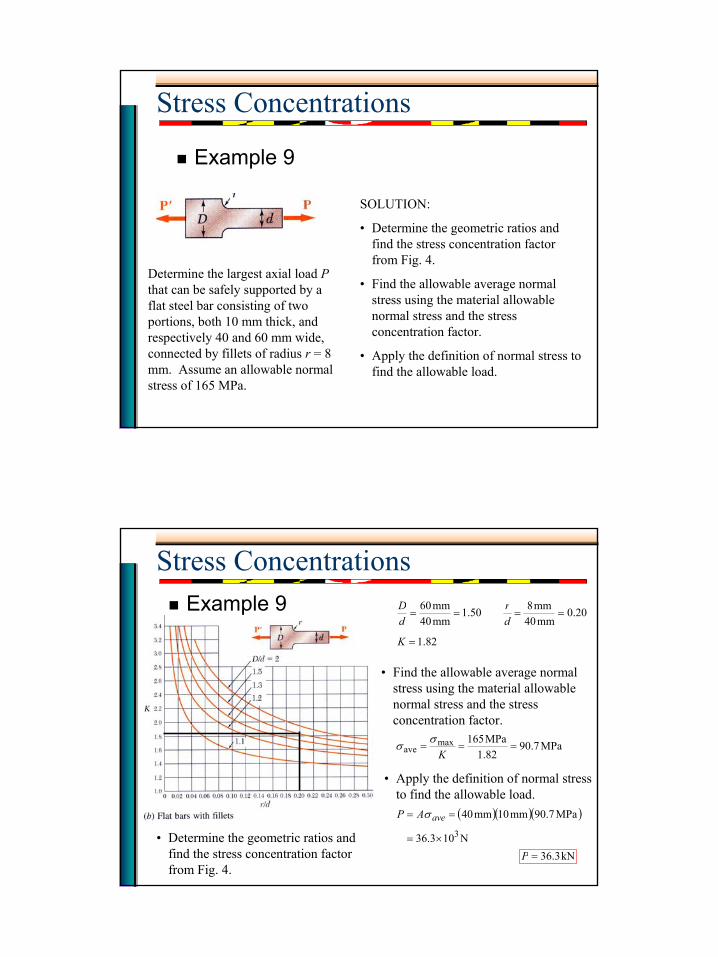
Example 9
Determine the largest axial load Pthat can be safely supported by a flat steel bar consisting of two portions, both 10 mm thick, and respectively 40 and 60 mm wide, connected by fillets of radius r = 8 mm. Assume an allowable normal stress of 165 MPa.
SOLUTION:
• Determine the geometric ratios and find the stress concentration factor from Fig. 4.
• Apply the definition of normal stress to find the allowable load.
• Find the allowable average normal stress using the material allowable normal stress and the stress concentration factor.
Stress ConcentrationsExample 9
• Determine the geometric ratios and find the stress concentration factor from Fig. 4.
82.1
20.0mm40
mm850.1mm40mm60
=
====
K
dr
dD
• Find the allowable average normal stress using the material allowable normal stress and the stress concentration factor.
MPa7.9082.1MPa165max
ave ===K
σσ
• Apply the definition of normal stress to find the allowable load.
( )( )( )
N103.36
MPa7.90mm10mm40
3×=
== aveAP σ
kN3.36=P