Embed Size (px)
Citation preview

concentration 1
STRESS CONCENTRATION
- Cracks always initiate at points of stress concentration. - A crack, once initiated, becomes an intense stress concentrator itself. - Two fundamental cases of plane elasticity: INFINITE PLATE CONTAINING A CIRCULAR HOLE (Kirsh, G, (1898), V.D.I., 42, 797-807)
→ Stress Concentration
INFINITE PLATE CONTAINING AN ELLIPTICAL HOLE (Kolosoff, G.V., On an application of complex function theory to a plane problem of the mathematical theory of elasticity, Yuriev, 1909; Inglis, C.E., (1913), Stresses in a plate due to the presence of cracks and sharp corners,Transactions of the Royal Institute of Naval Architectes, 60, 219-241)
→ Stress Concentration
concentration 2
- In the limit of (minor axis) / (major axis) → 0 : INFINITE PLATE CONTAINING A CRACK (Wieghardt, K., (1907), Z. Mathematik und Physik, 55, 60-103; translated by Rossmanith (1995), On splitting and cracking of elastic bodies, Fatigue Fract. Engrg. Mater. Struct., 18, 1371-1405) Muskhelishvili, N.I., Some basic problems of the mathematical theory of elasticity, in Russian 1933 (in English 1953, Noorhoff-Groningen). Westergaard, Bearing Pressures and cracks, (1937), J. Applied Mechanics, 6, A49-53. Williams, M.L. (1952), Stress singularities resulting from various boundary conditions in angular corners of plates in extension, J. Applied Mech., 19, 526-528. Williams, M.L. (1957), On the stress distribution at the base of a stationary crack, J. Applied Mech., 24, 109-114.)
→ Stress Intensification

concentration 3
INFINITE PLATE CONTAINING A CIRCULAR HOLE (Kirsh, G, (1898), V.D.I., 42, 797-807) - Consider infinite plate containing a circular hole of radius R and subject to a remote tensile stress σx = σ.
- Consider portion of plate within concentric circle of radius R' >> R so that stress field is not perturbed by hole (Saint- Venant’s Principle) - Stress field at r = R' (Mohr's circle):
( )
θσσ
θσσ
θ 22
212
sin
cos
−=
+=
r
r

concentration 4
- Decompose problem into:
Problem (1)
02 == θσσσ rr ,/ Problem (2)
( ) θσσθσσ θ 22
22
sin cos −== rr ,
- Solution problem (1): thick cylindrical tube under tension (Lamè):
22
2
222
22
22
2
222
22
RR'R'
rRR'R'R
RR'R'
rRR'R'R
−+
−+=
−+
−−=
21
2
21
2
σσσ
σσσ
θ
r
- For R' → ∞
++=
−+=
2
2
2
2
rR
rR
12
12
σσ
σσ
θ
r
concentration 5
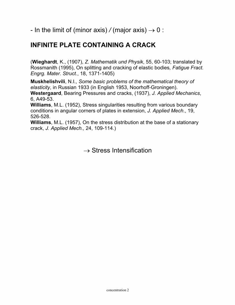
- Solution problem (2): Assume Airy stress function:
θcos2)(rf=Φ Impose compatibility, ∇4Φ = 0,
0112
2
2
22
2=Φ
∂
∂+
∂∂
+∂
∂
θrrrr
Substitute stress function and get the ordinary differential equation to determine f(r):
0412
22
2=
−+ frrrr d
dddcos2θ
General solution:
DrCBrArf +++= 2
42
Boundary conditions:
0)(0)(
22
)(
22
)(
==
−=
+=
RR
sinR'
cosR'
θ
θ
σσ
θσσ
θσσ
r
r
r
r

concentration 6
Recall:
θθσ
σ
θσ
θ
θ
∂∂Φ∂
−∂Φ∂
+=
∂
Φ∂+=
∂
Φ∂+
∂Φ∂
+=
rr1
r1r
r1
rr1
2
2
22
2
2
2
r
r
Substitute into general solution to get constants:
For R' → ∞ : 24 RD ,RC ,B ,A24
04
σσσ=−==−=
- Solution problems (1) + (2):
θσσ
θσσσ
θσσσ
θ
θ
22312
2312
12
24312
12
sinrR
rR
cosrR
rR
cosrR
rR
rR
2
2
4
4
4
4
2
2
2
2
4
4
2
2
+−−=
+−
+=
−++
−=
r
r

concentration 7
For r = R:
0221
0
=
−==
θσ
θσσσ
θ
r
r)( cos
Maximum stress: σσθ 3= for θ = π/2, 3π/2 Minimum stress: σσθ −= for θ = 0, π Note: - stress concentration factor = 3, independent of R - compression for −π/6 ≤ θ ≤ π/6 and −5π/6 ≤ θ ≤ 7π/6 - circumferential stress for θ = π/2:
++= 4
4
2
2
rR
rR 32
2σσθ
⇒ hole has a localized character
for r = 4R: ).( 0401+= σσθ
⇒ solution applicable to finite plates with width > 4R. - stress field satisfies plane-strain and generalized plane
stress.
concentration 8
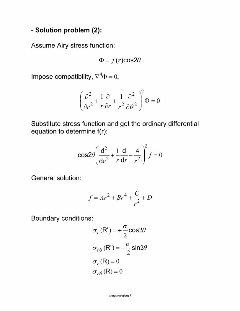
- INFINITE PLATE WITH CIRCULAR HOLE SUBJECT TO BIAXIAL STRESS
Apply superposition principle to get stresses at r = R: 1) Biaxial tension: Uniform stress: σσθ 2= 2) Tension/compression (pure shear): Maximum stress: σσσσθ 43 =+= for θ = π/2, 3π/2 Minimum stress: σσσσθ 43 −=−−= for θ = 0, π

concentration 9
INFINITE PLATE CONTAINING AN ELLIPTICAL HOLE (Kolosoff, G.V., On an application of complex function theory to a plane problem of the mathematical theory of elasticity, Yuriev, 1909; Inglis, C.E., (1913), Stresses in a plate due to the presence of cracks and sharp corners,Transactions of the Royal Institute of Naval Architectes, 60, 219-241) Hp: elliptical hole with: a = major axis, b = minor axis.
- Solution: Kolosof (complex function theory); Inglis (Conformal Mapping, elliptical coordinates) (see Carpinteri, Meccanica dei materiali e della frattura, 1992, Pitagora, for details). - For β = π/2 (tensile stress perpendicular to major axis): a = major axis, b = minor axis
σθ
θσθ
+
+=
2mcos2-m12cos22m-m-1
2
2
m=(a-b)/(a+b).
θ
σ

concentration 10
Maximum circumferential stress:
σσσσ θθ
+=
+
+==ba
m-1m1max 21210)(
- Other cases:
Tensile stress perpendicular to
major axis
+=
ba
max 21σσ
Tensile stress perpendicular to
minor axis
+=
ab
max 21σσ
Uniform stress σσ
ba
max 2=
Pure shear
+=
ba12σσmax
Pure shear parallel to major and minor axes
ab
b)(a 2max
+= σσ
- For a = b, solution for a circular hole (Kirsh); - For b/a → 0 and tensile stress perpendicular to major
axis: stress intensification;
- For b/a → 0 and tensile stress perpendicular to minor axis: uniform stress equal to applied load,
no stress concentration

intensification 1
STRESS INTENSIFICATION
Plate with a crack: stress intensification at the crack tip - What is the critical load in the cracked plate? - What is the "fine structure" of the stress field at the crack tip? - What is the power of the singularity? (e.g., 2D problem of a point load acting on a semi-infinite plane (Kelvin): stresses = O(r −1), displacements = O(log r))

intensification 2
Traditional design approach: (2 parameters: σapplied, σu)
σapplied < σu σu = yield or tensile strength ⇒ (a): σapplied < σu / 3 → safe ⇒ (b): σapplied < σu / (1+a/b) → safe ⇒ (c): σapplied ≠ 0 → unsafe for any σy
??? Fracture Mechanics approaches in design: (3 parameters: σapplied, GIC (or KIC), a) - Energy Approach:
the crack propagates when the energy available for crack growth
overcomes the material resistance (fracture toughness) - Stress Intensity Factor Approach:
the crack propagates when a local measure of the singular stress field
reaches a critical value (fracture toughness)
intensification 3
- Energy Approach: (Griffith, A.A., The phenomena of rupture and flow in solids, Philosofical Transactions, Series A, vol. 221, 1921, 163-198; Griffith, A.A., The theory of rupture, First Int. Congress of Applied Mechanics, Delft, 1924, 55-63;) - Stress Intensity Factor Approach: (Wieghardt, K., (1907), Z. Mathematik und Physik, 55, 60-103; translated by Rossmanith (1995), On splitting and cracking of elastic bodies, Fatigue Fract. Engrg. Mater. Struct., 18, 1371-1405) Muskhelishvili, N.I., Some basic problems of the mathematical theory of elasticity, in Russian 1933 (in English 1953, Noorhoff-Groningen). Westergaard, Bearing Pressures and cracks, (1937), J. Applied Mechanics, 6, A49-53. Williams, M.L. (1952), Stress singularities resulting from various boundary conditions in angular corners of plates in extension, J. Applied Mech., 19, 526-528. Williams, M.L. (1957), On the stress distribution at the base of a stationary crack, J. Applied Mech., 24, 109-114.)

intensification 4
CRACK TIP SINGULARITY IN AN INFINITE PLATE CONTAINING A CRACK
WESTERGAARD METHOD
(Westergaard, Bearing Pressures and cracks, (1937), J. Applied Mechanics, 6, A49-53.) (see Carpinteri, Meccanica dei materiali e della frattura, for details)
Hp: homogeneous, isotropic, linearly elastic body
plane stress crack length = 2a biaxial load:
k )(z
)(z
x
y
σσ
σσ
=∞=
=∞=
with k = real constant, k- ∞≤≤∞ Problem: define stress field at crack tip

intensification 11
Stress field ahead of the crack tip in an infinite cracked plate (symmetry about x axis)
( )
( )
23
22
23
22
23
22 2
θθθ
θθθ
θθθ
πσ
πσ
πσ
sincossinr 2
K
sinsin1cosr 2
K
Bsinsin-1cosr 2
K
I
I
I
=
+=
+=
xy
y
x
Note: - General expression for the stress components:
)(θπ
σ ijij II f
r 2K
=
- inverse square root singularity in all stress components: - power of the singularity and fIij(θ) depending on crack face boundary conditions and unaffected by remote boundary conditions - stress field univocally defined by KI (now still unknown): → KI is a measure of the singular stress field → single parameter description of crack tip conditions - KI units: [F] [L] -3/2 - Singularity dominated zone
intensification 13
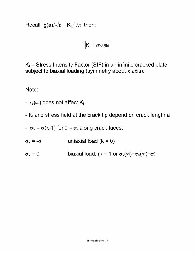
Recall πIKag(a) = then:
aKI πσ= KI = Stress Intensity Factor (SIF) in an infinite cracked plate subject to biaxial loading (symmetry about x axis): Note: - σx(∞) does not affect KI. - KI and stress field at the crack tip depend on crack length a - σx = σ(k-1) for θ = π, along crack faces: σx = -σ uniaxial load (k = 0) σx = 0 biaxial load, (k = 1 or σx(∞)=σy(∞)=σ)

intensification 14
EFFECT OF FINITE SIZE: MODE I PROBLEMS IN FINITE BODIES
- Stresses at the crack tip:
)(θπ
σ ijij II f
r 2K
=
- Stress Intensity Factor in finite body:
F aKI πσ= F dimensionless function, typically a polynomial expression, depending on geometry and loading conditions.

intensification 15
Examples: - Cracked strip in tension:
1/2
1/2
I
2hasec
haFF
2hasec aK
=
=
=
π
ππσ
guess based on numerical solution
haF
- Three point bending beam:
9/27/25/2
3/21/2
3/2I
ha 38.7-
ha 37.6-
ha 21.8
ha 4.6-
ha2.9
haF
haF
thPlK
+
+
=
=
intensification 16
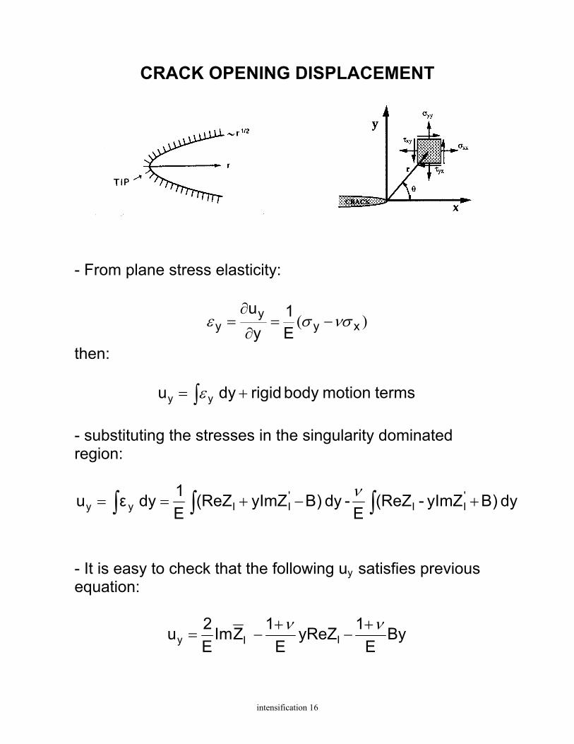
CRACK OPENING DISPLACEMENT
- From plane stress elasticity:
)( xyy
y E1
yu
νσσε −=∂
∂=
then:
terms motionbody rigid dy u yy += ∫ε - substituting the stresses in the singularity dominated region:
dy )ByImZ-(ReZE
-dy )ByImZ(ReZE1dy εu '
II'IIyy ∫∫∫ +−+==
ν
- It is easy to check that the following uy satisfies previous equation:
ByE
1yReZE
1ZImE2u IIy
νν +−
+−=

intensification 17
- using the complex potential:
CBξ2ξ2KZ 1/2I
I ++=π
- and polar coordinates:
C)Br(r2
2KZ 1/2II ++++= θθθθ
πsincos)
2sin
2(cos ii
-so that:
1/2I1/2
yy r EK24uuCOD
=−=−==π
πθπθ )()(
Note: - COD depends on KI/E and increases on increasing KI/E - COD is parabolic along the crack, COD ≈ r1/2
- COD has a vertical tangent in r = 0
intensification 18
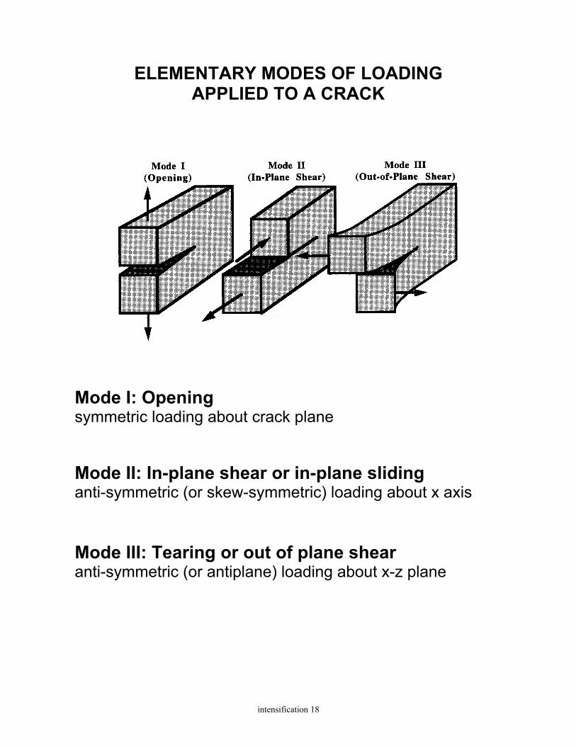
ELEMENTARY MODES OF LOADING APPLIED TO A CRACK
Mode I: Opening symmetric loading about crack plane Mode II: In-plane shear or in-plane sliding anti-symmetric (or skew-symmetric) loading about x axis Mode III: Tearing or out of plane shear anti-symmetric (or antiplane) loading about x-z plane
intensification 19
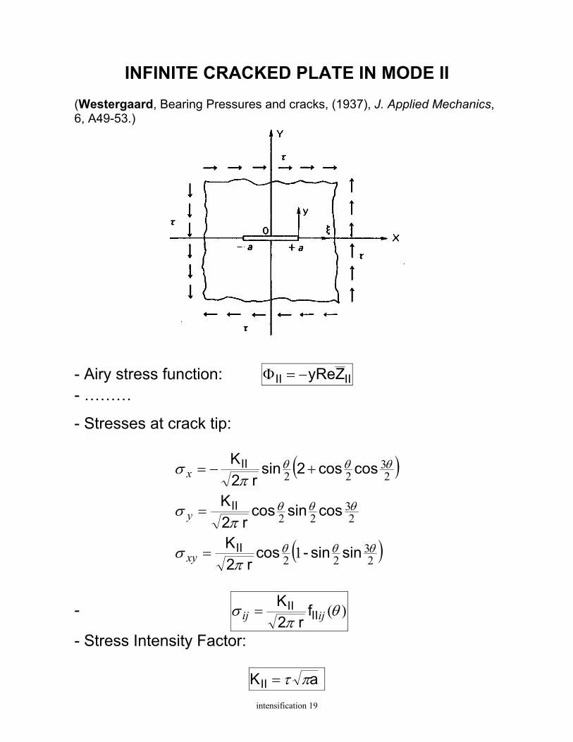
INFINITE CRACKED PLATE IN MODE II
(Westergaard, Bearing Pressures and cracks, (1937), J. Applied Mechanics, 6, A49-53.)
- Airy stress function: IIII ZyRe−=Φ
- ………
- Stresses at crack tip:
( )
( )23
22
23
22
23
22
1 θθθ
θθθ
θθθ
πσ
πσ
πσ
sinsin-cosr 2
K
cossincosr 2
K
coscos2sinr 2
K
II
II
II
=
=
+−=
xy
y
x
- )(θπ
σ ijij IIII f
r 2K
=
- Stress Intensity Factor:
aKII πτ=

intensification 20
STRESS FIELD AHEAD OF THE CRACK TIP
Mode I: ( )
( )
stress plane in strain, plane in
sincossinr 2
K
sinsin1cosr 2
K
Bsinsin-1cosr 2
K
I
I
I
0)(
0
2
23
22
23
22
23
22
=+=
==
=
+=
+=
zyxz
yzxz
xy
y
x
σσσνσ
σσπ
σ
πσ
πσ
θθθ
θθθ
θθθ
Mode II:
( )
( )
stress plane in strain, plane in
sinsin-cosr 2
K
cossincosr 2
K
coscos2sinr 2
K
II
II
II
0)(
0
1 23
22
23
22
23
22
=+=
==
=
=
+−=
zyxz
yzxz
xy
y
x
σσσνσ
σσπ
σ
πσ
πσ
θθθ
θθθ
θθθ
Mode III:
0
2
2
====
=
−=
xxyyx
yz
xz
σσσσπ
σ
πσ
θ
θ
cosr 2
K
sinr 2
K
III
III

intensification 21
CRACK TIP DISPLACEMENT FIELDS Mode I:
=u2
2sin + 1)- 2
cos 2r
GK = u
2 2cos - 1) sin
2r
GK =u
z
2 Ix
2 Iy
0
(2
(22
+
θκθπ
θκθπ
Mode II:
0 =u2
cos 2+ 1) sin 2r
2GK u
2 sin 2- 1)
2 cos
2r
2GK =u
z
2IIx
2IIy
++=
−−
θκθπ
θκθπ
(2
(
Mode III:
0 =u0 u
sin2r GK =u
y
x
III z
=
− 2
θπ
where: κ = 3−4ν (plane strain) κ = (3−ν)/(1+ν) (plane stress)

intensification 23
SIF EVALUATION
- Close form solutions:
complex function theory (conformal mapping, boundary collocation method, Laurent series expansion,… integral transforms (Fourier, Mellin, Hanckel transforms) eigenfunction expansion
limited to very simple cases - Computational solutions (FEM, BEM, FDM, …) - Experimental solutions (photoelasticity, moire interferometry,…) - Fracture handbooks Tada, Paris and Irwin, (1985), The stress analysis of cracks handbook, Paris Prod., Inc., St. Luis (II edition). Murakami (1987), Stress Intensity Factor handbook, Pergamon Press, NY. Rooke and Cartwright, (1976), Compendium of Stress Intensity Factors, Her Majesty’s Stationary Office, London.

intensification 24
Tada, Paris and Irwin, (1985), The stress analysis of cracks handbook

intensification 28
STRESS INTENSITY FACTOR SUPERPOSITION PRINCIPLE
- For linear elastic materials individual components of stress, strain and displacement are additive. - Similarly, stress intensity factors are additive:
...
...
...
+++=
+++=
+++=
(C)(B)(A)III
(C)(B)(A)II
(C)(B)(A)I
IIIIIIIII
IIIIII
III
KKKK
KKKK
KKKK
where:
(i)(i)(i)IIIIII
K ,K K , (i = A, B, C, ….) are mode I, mode II and mode III stress intensity factors for the ith applied load. Example:
(SENT)
I IKK =
(SENB)
I IKK =
(SENB)(SENT)
I IIKKK +=

intensification 31
SUPERPOSITION PRINCIPLE
Any loading configuration can be represented by appropriate tractions applied directly to the crack faces Proof:
intensification 32
SUPERPOSITION PRINCIPLE
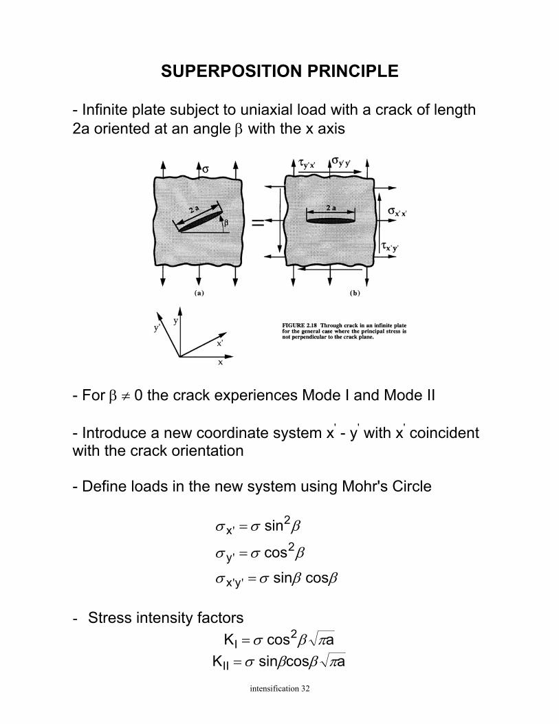
- Infinite plate subject to uniaxial load with a crack of length 2a oriented at an angle β with the x axis
- For β ≠ 0 the crack experiences Mode I and Mode II - Introduce a new coordinate system x' - y' with x' coincident with the crack orientation - Define loads in the new system using Mohr's Circle
cos sin
cos
sin
yx
2y
2x
ββσσ
βσσ
βσσ
=
=
=
''
'
'
- Stress intensity factors
acos K 2I πβσ=
acossin KII πββσ=

mixed mode 1
MIXED MODE FRACTURE
Assumptions: homogeneous, isotropic, linear elastic material plane problem (Mode I + Mode II)
Griffith’s Energy Criterion applies only to collinear crack growth A Criterion for Mixed Mode fracture must define: a) the direction of crack growth b) the critical values of the fracture parameters MAXIMUM CIRCUMFERENTIAL STRESS CRITERION (Erdogan and Sih, (1963), On crack extension in plates under plane loading
and transverse shear, J. Basic Engineering, 85, 519-527)

mixed mode 2
Example of Application - Cracked plate subject to biaxial load σ1 - σ2
- Assume: m = σ1 / σ2 β = crack direction about σ2
- Crack tip stress intensity factors: a K
a K
II
I
πτ
πσ
β
β
=
=

mixed mode 3
Direction of crack growth The crack propagates in a direction normal to the maximum circumferential stress σθ
Special cases: 1) m = 1 , σ1 = σ2 ⇒ Mohr’s circle degenerates
into a point symmetry about crack direction
01
=
=
β
β
τ
σσ ⇒ KII = 0, θ = 0
⇒ collinear crack growth 2) m = 0, σ1 = 0 (uniaxial tension)
if β = 0 ⇒ θ = 0 collinear crack growth
if β ≠ 0 ⇒ °==→ + 70.6)0,(m
0lim
βθβ

mixed mode 4
Criterion for crack growth The Mixed-Mode crack will propagate along θ when σθ = σθcr(Mode I)
Fracture locus
- the fracture locus is symmetric about the K*I axis - the fracture locus is not defined for KI < 0

energy approach 2
GRIFFITH ENERGY CRITERION
(Griffith, A.A., The phenomena of rupture and flow in solids, Philosofical Transactions, Series A, vol. 221, 1921, 163-198; Griffith, A.A., The theory of rupture, First Int. Congress of Applied Mechanics, Delft, 1924, 55-63;) - First law of Thermodynamics: when a system goes from a nonequilibrium state to equilibrium there will be a net decrease in energy → A crack can form in a body only if such a process causes the total energy to decrease or remain constant (Griffith) - Consider an infinite plate of unit width subject to biaxial load in plane stress conditions. Imagine to create a crack of length 2a while keeping the remote displacements constant
The elastic strain energy released is proportional to the strain energy contained in a circle of radius a (after Inglis):
EaW
22
eσπ=

energy approach 3
The strain energy, W, of the cracked plate is then given by:
Ea-WW-WW
22
0e0σπ==
where W0 is the strain energy of the uncracked plate.
- The energy required to create the crack surface is:
ss aW γ4= - An incremental crack extension da is possible if:
0da
dWdadW s ≤+
s
24
Ea γσπ ≥2
aEs
πγσ 2
≥
(substitute E with E’ for plane strain)
energy approach 4
Fracture Energy:
GIC = 2 γs
= energy required to create a unitary crack area. (crack area = 2a; surface area = 4a) - measure of the fracture toughness of the material - to be defined through standard tests
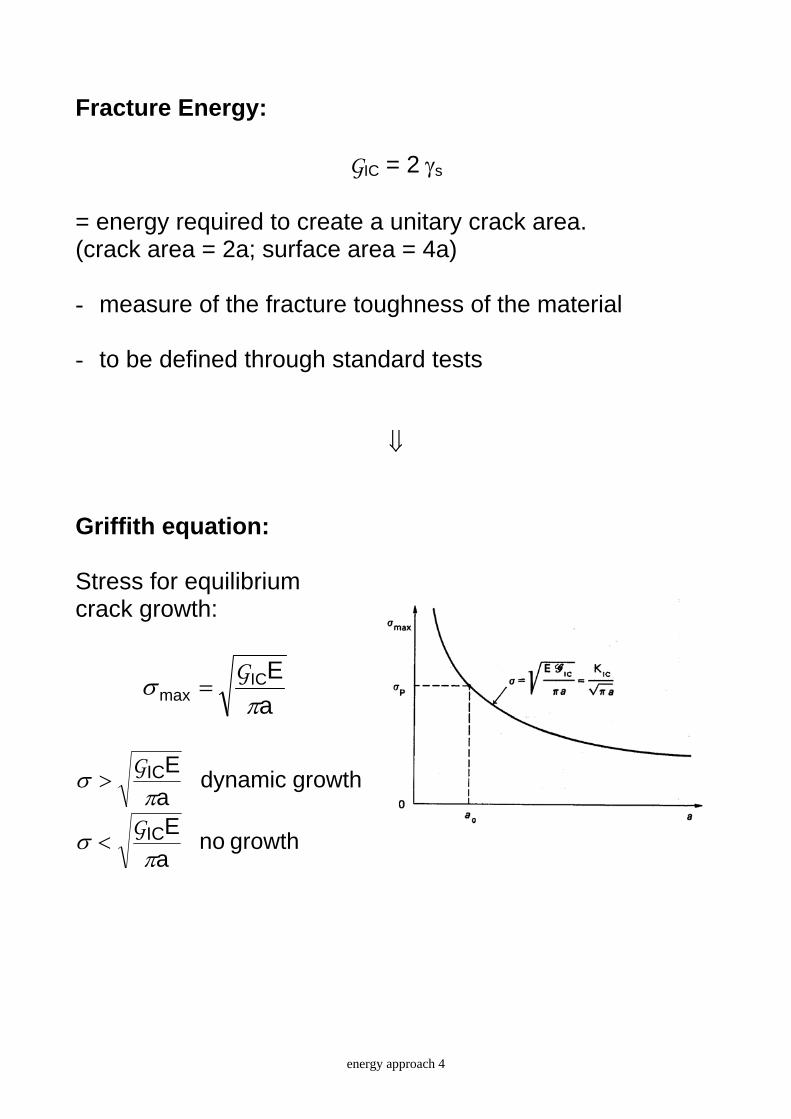
⇓ Griffith equation: Stress for equilibrium crack growth:
aEIC
max πσ
G=
growthdynamic aEIC
πσ G
>
growth no aEIC
πσ G
<

energy approach 5
Stress for equilibrium crack growth:
aEIC
max πσ G
=
growthdynamic aEIC
πσ G
>
growth no aEIC
πσ G
<
- crack growth is unstable: the load decreases on increasing the crack length - two asymptotes: • for a →∞, σmax → 0
• for a →0 σmax → ∞ ???? analogy with buckling collapse vs. strength collapse: for a<a0 the strength collapse precedes the fracture collapse - The crack length a0 corresponding to σmax = σy ( = σp) is an equivalent measure of the microcracks, flaws and defects of the virgin material:
2y
IC0
Eaσπ
G1=

energy approach 6
MODIFIED GRIFFITH EQUATION
(Irwin, (1948), Fracture Dynamics, Fracturing of Metals, ASM Cleveland, 146-166; Orowan,(1948), Fracture and strength of solids, Reports on Progress in Physics, XII, p. 195.) - In actual structural materials: a) the energy needed to cause fracture is much higher than the surface energy (orders of magnitude higher) b) inelastic deformations arise around the crack front → linear elastic medium with infinite stresses at the crack tip unrealistic - Griffith equation can be modified to include the plastic work γP dissipated at the crack front
a)E( ps
πγγ
σ+
≥2
- Orowan estimated γP ≈ 103 γs in typical metals. - The modified Griffith equation is correct only if: the size of the plastic zone around the crack tip is very small compared to the crack size (small-scale yielding conditions) → the details of the crack tip stress do not affect the stress field in the elastic bulk of the medium → purely elastic solutions can be used to calculate the rate of energy available for fracture (!!!!!!!!)

energy approach 7
ENERGY BALANCE IN BRITTLE FRACTURE
- Griffith criterion refers to a special case, i.e. infinite cracked plate, biaxial loading, fixed-grip conditions - In general, the First Law of Thermodynamics yields:
0dA
dWdAdW
dAdE sT ≤+=
A = crack area ET = total energy Ws = energy required to create new crack surfaces W = total potential energy W = U - L U = potential strain energy L = potential of external forces - From the definition of fracture energy:
ICss 2
dAdW
G== γ
- Energy criterion for brittle crack growth (Mode I):
ICdAdW
G≥−

energy approach 8
THE STRAIN ENERGY RELEASE RATE (Irwin, (1957), Analysis of stresses and strains near the end of a crack traversing a plate. ASME Journal of Applied Mechanics, 24, 361-364) - Irwin introduced the Strain Energy Release Rate
dAdW
−=G
as the energy available for an increment of crack extension, given by the total potential energy released due to the formation of a unit crack area - G is also called Crack Driving Force or Crack Extension Force - Energy criterion for brittle crack growth (Mode I):
ICI GG =

energy approach 9
ENERGY APPROACH VS. STRESS APPROACH (CRITICAL CONDITIONS)
- The strain energy release rate is the fracture parameter describing the global behavior of the body. - The stress intensity factor if the fracture parameter describing the local behavior (stresses, strains and displacements near the crack tip) of the body - Stress criterion for brittle crack growth (Mode I):
ICI KK ≥
KIC = critical stress intensity factor KIC is a measure of the material fracture toughness to be defined through standard tests - ICG and KIC are related through a fundamental relationship
EK2
ICIC =G
derived from:
conditiony instabilitenergy aEIC
πσ G
≥
conditiony instabilit stress a
KICπ
σ ≥
⇓ EK ICIC G=

energy approach 17
STRAIN ENERGY RELEASE RATE IN A DCB SPECIMEN
- Assume built-in end conditions for the two arms. From beam theory:
3
33
EBh4Pa
3EIPa/2 ==Δ
- The elastic compliance is:
3EI2a
PC
3=
Δ=
- The strain energy release rate in the DCB specimen is:
3
2
2
2
Eha
BP 12
3EI6a
2BP
dadC
2BP 222
===G
- Same conclusion from:
3
2
2
232
Eha
BP 12
EIa
BP
3EIaP
dad
B1P
21
dad
B1
BdadW 22
==⎟⎟⎠
⎞⎜⎜⎝
⎛=⎟
⎠⎞
⎜⎝⎛ Δ−−=−=G

energy approach 18
- The critical load for crack propagation (Griffith criterion) is
12BEh
a1P
23IC
crG
=
⇒ unstable crack growth Note: Strain energy release rate and critical load have been defined through a beam theory approximation.
If the geometry satisfies the assumptions of beam theory the solution is correct. However, the local fields at the crack tip are not correctly given by beam theory

energy approach 19
ENERGY RELEASE RATE IN A BODY SUBJECT TO DIFFERENT LOADING SYSTEMS
Hp: self-similar crack growth - From the stress intensity factors of a body subject to different loading systems (A), (B), (C),…..
...
...
...
+++=
+++=
+++=
(C)(B)(A)III
(C)(B)(A)II
(C)(B)(A)I
IIIIIIIII
IIIIII
III
KKKK
KKKK
KKKK
and the relationship between G and K
2GK
EK
EK 2
III2II
2I ++=G
⇒ the strain energy release rate is
2G....)K(K
E...)K(K
E....)KK(K 2(B)
III(A)III
2(B)II
(A)II
2(C)I
(B)I
(A)I ++
+++
++++
=G

energy approach 20
- The strain energy release rate contributions for each mode of fracture are addictive
2GK
EK
EK 2
III2II
2I ++=++= IIIII GGGG
- The strain energy release rate contributions for each loading system are not addictive, e.g. for mode I
...+++≠+++ (C)I
(B)I
(A)I
...(C)(B)(A)I GGGG

cohesive crack model 1
NONLINEAR FRACTURE MECHANICS THE COHESIVE CRACK MODEL
(Dugdale, D.S.: Yielding of steel sheets containing slits, J. Mechanics Physics Solids 8 (1960), 100-104 Barenblatt, G.I.: The formation of equilibrium cracks during brittle fracture. General ideas and hypotheses. Axially-symmetric cracks, J. Applied Mathematics and Mechanics 23 (1959), 622-636. Barenblatt, G.I.: The mathematical theory of equilibrium cracks in brittle fracture, in H.L. Dryden and T. von Karman (eds.), Advanced in Applied Mechanics, Academic Press, New York, 1962, pp. 55-129.)
ductile materials ⇒ Dugdale’s model purely brittle materials ⇒ Barenblatt’s model quasi brittle materials ⇒ Hillerborg’s Fictitious (e.g. concrete) Crack Model brittle matrix composites ⇒ Bridged crack model quasi brittle matrix composites ⇒ Cohesive crack model

cohesive crack model 2
Dugdale’s Model for ductile fracture
Fracture of elasto-plastic materials Assumptions: - Mode I crack in an infinite sheet under uniform tensile stress
- the material is ductile and the plastic deformations localized in a thin zone coplanar with the crack
- the plastic zone is modeled through a fictitious crack (of unknown length) and a uniform distribution of cohesive tractions σP = yield stress
Length of the cohesive zone The length of the cohesive zone aP is calculated by imposing the condition of smooth closure of the crack faces:
0KKK PIII =+= σσ
where: )( PI aa K += πσσ

cohesive crack model 3
The SIF due to the plastic stresses is calculated using the SIFs due to a pair of concentrated forces F acting at x:
1/2
I
1/2
I
xaxa
aF(B)K
xaxa
aF(A)K
⎟⎠⎞
⎜⎝⎛
+−
=
⎟⎠⎞
⎜⎝⎛
−+
=
π
π
so that:
∫ ⎥⎦
⎤⎢⎣
⎡++−+
+−+++
+=
P
P
a
a P
P
P
P
P
PI dx
x)a(ax)a(a
x)a(ax)a(a
)aa- K
(πσ
σ
)()(2
P
PPI aa
aarccosaa- (a)K P ++
=π
σσ
From the condition for smooth closure:
0aa
aarccosaaaaP
PPP =
++
−+)(
)(2)(π
σπσ
PP 2cos
aaa
σπσ
=+
In the limit σ = 0 ⇒ aP = 0
σ → σP ⇒ aP → ∞

cohesive crack model 4
Performing a Taylor series expansion (if σ << σP): 2
⎟⎟⎠
⎞⎜⎜⎝
⎛−=
+ PP 2211
aaa
σπσ
2P
22
P
P
8aaa
σσπ
=+
and, as a function of KIσ,
2P
2I
PK
8 a
σπ σ=
Length of the cohesive zone in critical conditions Following Irwin's approach:
2P
2IC
PCK
8 a
σπ
=
where: EK ICIC G=
and: ==∫ aP0
P σdσa
δδδ
ICG
with δa the crack tip opening displacement given by:
⎥⎦
⎤⎢⎣
⎡⎟⎟⎠
⎞⎜⎜⎝
⎛=
P
Pa 2
seclnE
a8 σ
πσπσδ or E
K P
2I
a σδ = (if σ << σP)
(use Castigliano's method)
cohesive crack model 5
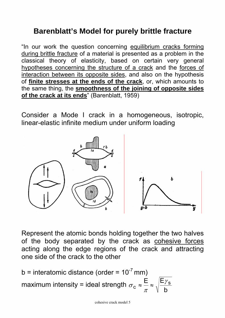
Barenblatt’s Model for purely brittle fracture “In our work the question concerning equilibrium cracks forming during brittle fracture of a material is presented as a problem in the classical theory of elasticity, based on certain very general hypotheses concerning the structure of a crack and the forces of interaction between its opposite sides, and also on the hypothesis of finite stresses at the ends of the crack, or, which amounts to the same thing, the smoothness of the joining of opposite sides of the crack at its ends” (Barenblatt, 1959)
Consider a Mode I crack in a homogeneous, isotropic, linear-elastic infinite medium under uniform loading
Represent the atomic bonds holding together the two halves of the body separated by the crack as cohesive forces acting along the edge regions of the crack and attracting one side of the crack to the other b = interatomic distance (order = 10-7 mm)
maximum intensity = ideal strength b
EE sc
γπ
σ ≈≈

cohesive crack model 6
Determination of the cohesive forces The accurate determination of the cohesive forces acting along the edge regions is difficult - Assumptions: 1) The dimension of the edge region is small in comparison with the size of the whole crack 2) The displacements in the edge region, for a given material under given conditions, is always the same for any acting load ⇒ during crack propagation the edge region simply translate forward 1) + 2) = small scale yielding assumption 3) The opposite sides of the crack are smoothly joined at the ends or, which amounts to the same thing, the stress at the end of a crack is finite
⇒ K = 0 (zero stress intensity factor)
These assumptions lead to the definition of the critical state of mobile equilibrium which depends on the modulus of cohesion depending on the integral of the cohesive tractions along the edge region

cohesive crack model 7
Equivalence of Griffith and Barenblatt approaches Willis (by means of the complex variable method) and Rice (by means of the J integral) proved that: Barenblatt’s theory based on atomic forces is equivalent to Griffith’s energy approach provided the integral of the cohesive forces is equal to the fracture energy
IC
*y
0dy f G=∫
Barenblatt also showed that the cohesive forces essentially have effect only on the displacement field close to the edge of the crack and not on those in the main part of the crack

cohesive crack model 8
Rice’s proof of the equivalence between Barenblatt’s model and Griffith’s energy approach
- Assume the crack to be in a state of mobile equilibrium - Consider cohesive forces σ(δ) acting along the crack - Let δ∗ to be the separation distance beyond which the cohesive tractions vanish
- Consider the path Γ for which: dy = 0, ds = dx on Γ− and ds = -dx on Γ+ , T1 = 0, T2 = σ(δ) on Γ+ , T2 = -σ(δ) su Γ− -Evaluate the J integral along Γ:
⇒∂∂
=∂∂
=
=∂∂
∂∂
=∂∂
∂∂
=⎟⎠⎞
⎜⎝⎛
∂∂
⋅−=
∫∫
∫∫∫∫∫++
+
+
+
ΓΓΓ +−
dxx
)(-)dxu-(ux
)(-
(-dx)xu)(-(dx)
xu)(--ds
xu-ds
xu-ds
xuTdyUJ
da
a
da
a
-22
a2
da22
22
2i
id
δδσδσ
δσδσada
TT
∫=*
)(δ
δδσ0
dJ
⇒ The value of J which will cause crack extension is given by the integral of the cohesive forces:
⇒ IC
*
0d )( G=∫ δδσ
δ