Embed Size (px)
Citation preview
Lecture 6
Design Concepts and Principles
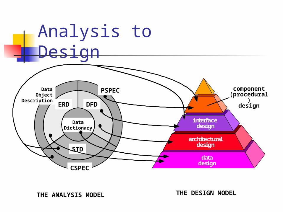
Analysis to Design
DataDictionary
THE ANALYSIS MODEL
interfacedesign
architecturaldesign
datadesign
THE DESIGN MODEL
PSPEC
CSPEC
ERD DFD
STD
DataObject
Description
component(procedural)
design
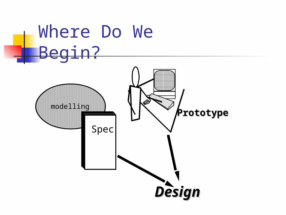
Where Do We Begin?
Spec
PrototypePrototype
DesignDesign
modelling
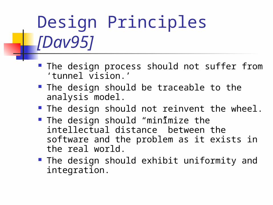
Design Principles [Dav95] The design process should not suffer from
‘tunnel vision.’ The design should be traceable to the
analysis model. The design should not reinvent the wheel. The design should “minimize the intellectual
distance” between the software and the problem as it exists in the real world.
The design should exhibit uniformity and integration.
Design Principles [Dav95] The design should be structured to
accommodate change. The design should be structured to degrade
gently, even when aberrant data, events, or operating conditions are encountered.
Design is not coding, coding is not design. The design should be assessed for quality
as it is being created, not after the fact. The design should be reviewed to minimize
conceptual (semantic) errors.
Fundamental Concepts abstraction—data, procedure, control refinement—elaboration of detail for all
abstractions modularity—compartmentalization of data and
function architecture—overall structure of the software
Structural properties Extra-structural properties Styles and patterns
procedure—the algorithms that achieve function hiding—controlled interfaces
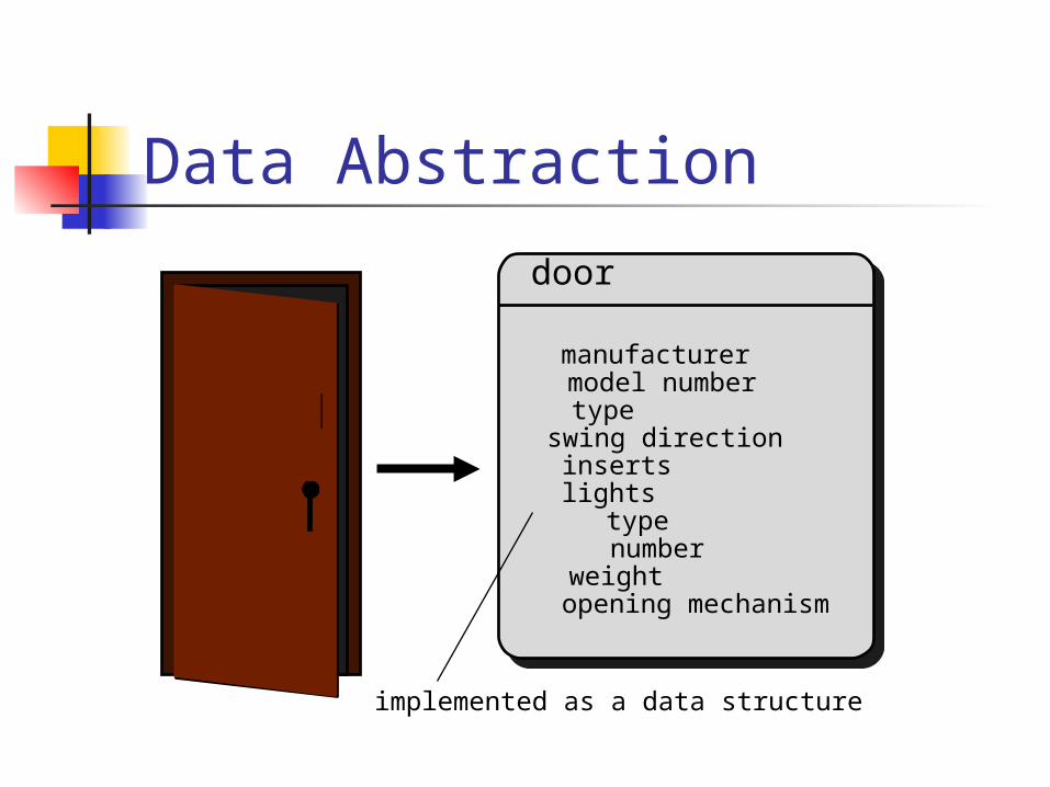
Data Abstraction
door
implemented as a data structure
manufacturermodel numbertypeswing directioninsertslights type numberweightopening mechanism
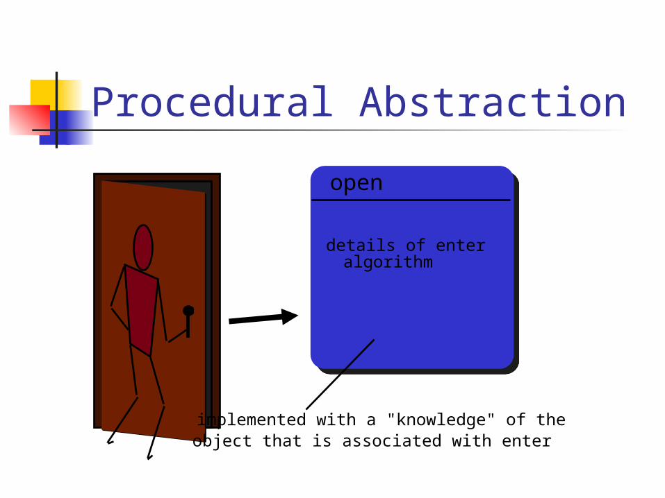
Procedural Abstraction
open
implemented with a "knowledge" of the object that is associated with enter
details of enter algorithm
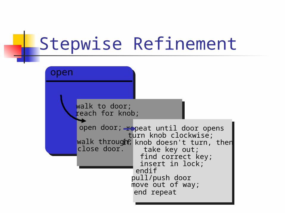
Stepwise Refinement
open
walk to door;reach for knob;
open door;
walk through;close door.
repeat until door opensturn knob clockwise;if knob doesn't turn, then take key out; find correct key; insert in lock;endifpull/push doormove out of way;end repeat
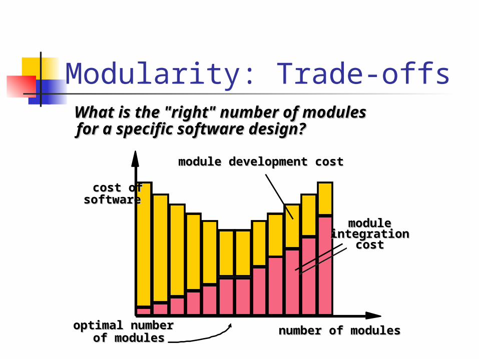
Modularity: Trade-offsWhat is the "right" number of modules What is the "right" number of modules for a specific software design?for a specific software design?
optimal numberoptimal number of modulesof modules
cost ofcost of softwaresoftware
number of modulesnumber of modules
modulemoduleintegrationintegration
costcost
module development cost module development cost
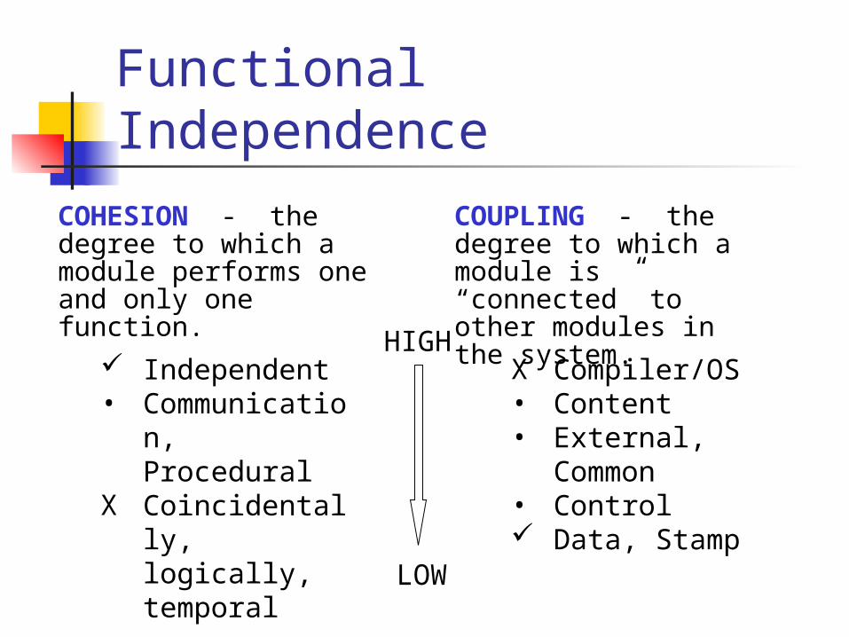
Functional Independence
HIGH
LOW
X Compiler/OS• Content• External,
Common• Control Data, Stamp
Independent• Communicatio
n, ProceduralX Coincidentally,
logically, temporal
COHESION - the degree to which a module performs one and only one function.
COUPLING - the degree to which a module is “connected” to other modules in the system.
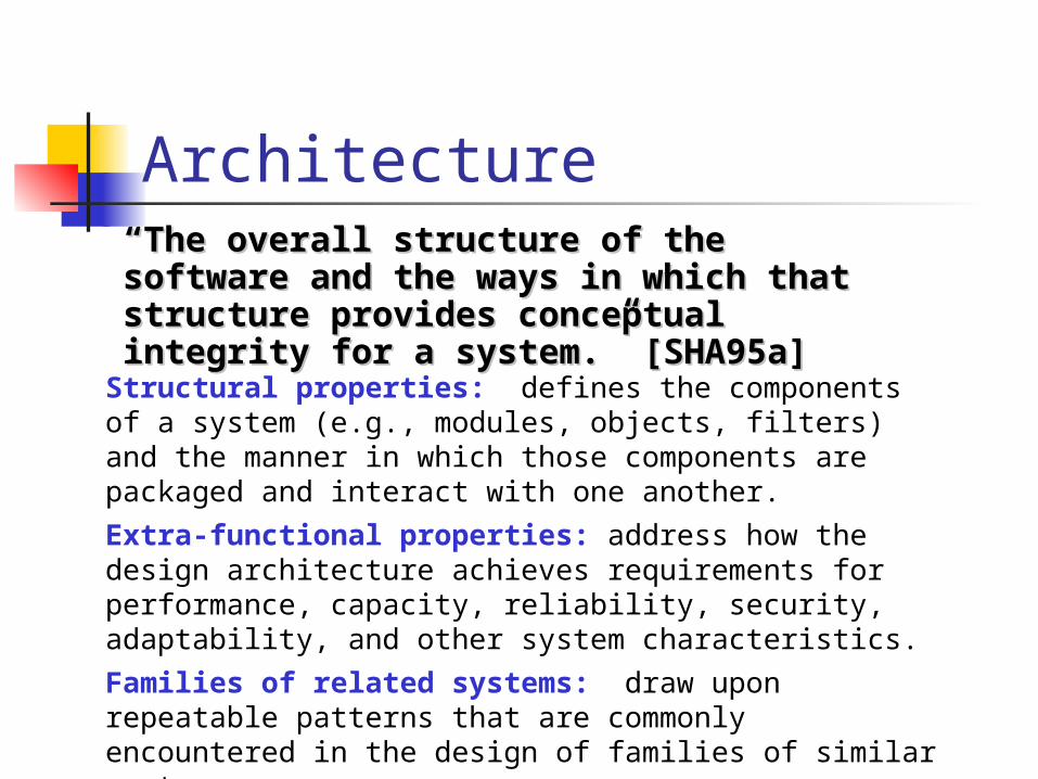
Architecture““The overall structure of the software and the The overall structure of the software and the ways in which that structure provides ways in which that structure provides conceptual integrity for a system.” [SHA95a]conceptual integrity for a system.” [SHA95a]
Structural properties: defines the components of a system (e.g., modules, objects, filters) and the manner in which those components are packaged and interact with one another.
Extra-functional properties: address how the design architecture achieves requirements for performance, capacity, reliability, security, adaptability, and other system characteristics.
Families of related systems: draw upon repeatable patterns that are commonly encountered in the design of families of similar systems.
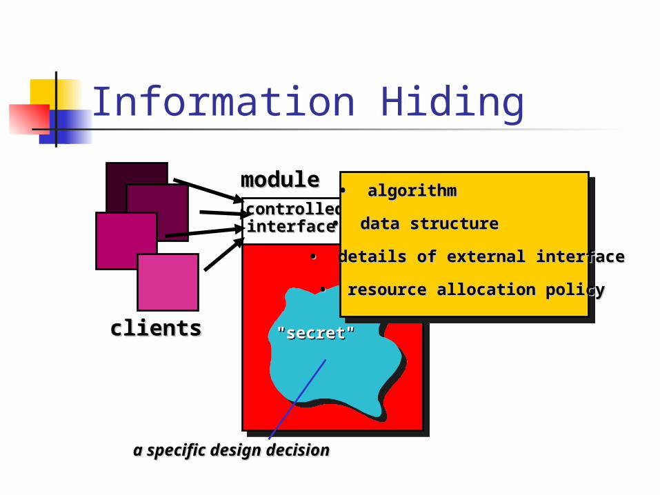
Information Hiding
modulemodulecontrolledcontrolledinterfaceinterface
"secret""secret"
• • algorithmalgorithm
• • data structuredata structure
• • details of external interfacedetails of external interface
• • resource allocation policyresource allocation policy
clientsclients
a specific design decisiona specific design decision

Architectural Design
Why Architecture?The architecture is not the operational software.
Rather, it is a representation that enables a software engineer to:
1. analyze the effectiveness of the design in meeting its stated requirements,
2. consider architectural alternatives at a stage when making design changes is still relatively easy, and
3. reduce the risks associated with the construction of the software.
Data Design refine data objects and develop a set
of data abstractions implement data object attributes as
one or more data structures review data structures to ensure that
appropriate relationships have been established
simplify data structures as required
Component Level Data Design
1. Apply systematic analysis principles to function and behavior to data.
2. Identify all data structures and the operations to be performed on them
3. Establish a data dictionary. 4. Defer low level data design decisions. 5. Reveal data structure representation only to
those modules that must make direct use of its content.
6. Develop a library of useful data structures and the operations that may be applied to them
7. Abstract data types should be supported.
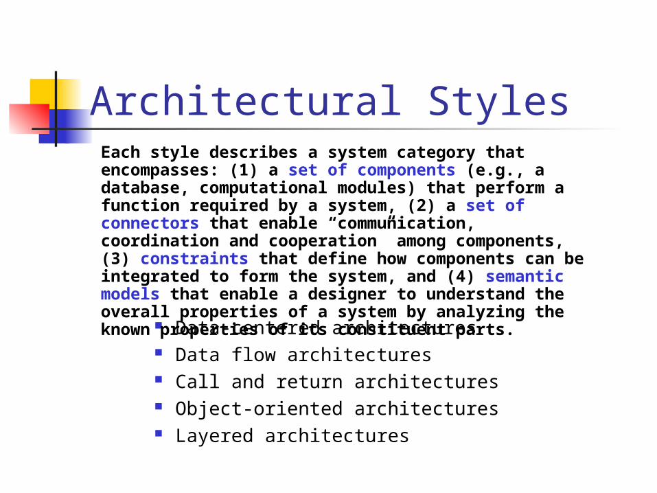
Architectural Styles
Data-centered architectures Data flow architectures Call and return architectures Object-oriented architectures Layered architectures
Each style describes a system category that encompasses: (1) a set of components (e.g., a database, computational modules) that perform a function required by a system, (2) a set of connectors that enable “communication, coordination and cooperation” among components, (3) constraints that define how components can be integrated to form the system, and (4) semantic models that enable a designer to understand the overall properties of a system by analyzing the known properties of its constituent parts.
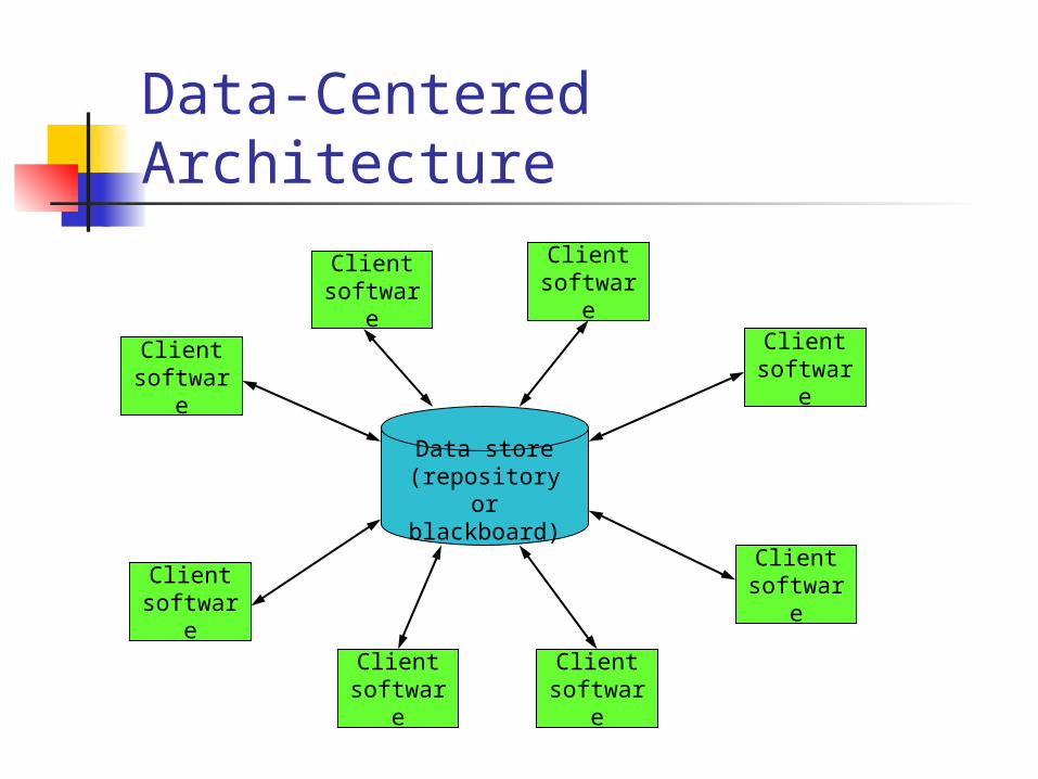
Data store(repository or blackboard)
Client software
Client software
Client software
Client software
Client softwareClient
software
Client software
Client software
Data-Centered Architecture
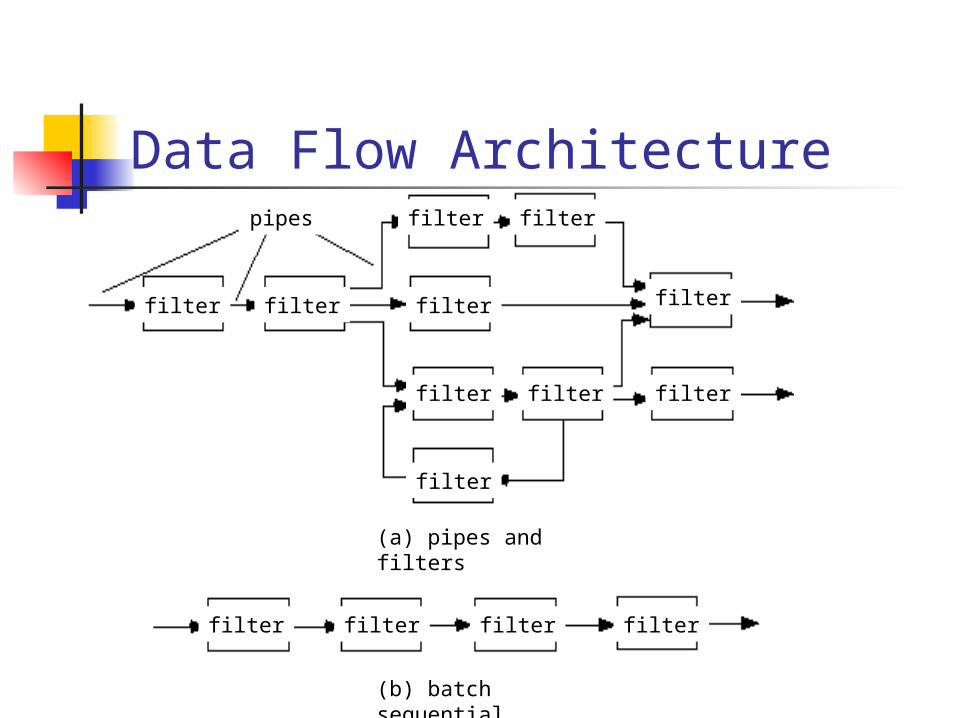
Data Flow Architecture
filter filter filter filter
filter filter
filter filter filter
filter
filter filter filter filter
pipes
(a) pipes and filters
(b) batch sequential
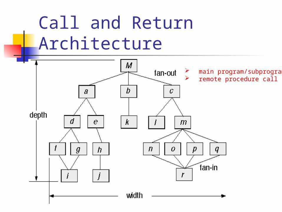
Call and Return Architecture
main program/subprogram remote procedure call
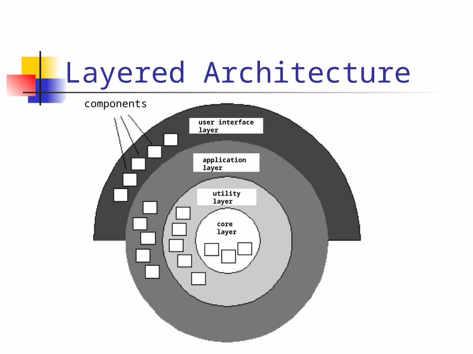
Layered Architecturecomponents
user interface layer
application layer
utility layer
core layer
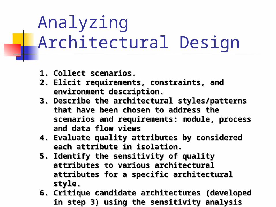
Analyzing Architectural Design
1.1. Collect scenarios. Collect scenarios. 2.2. Elicit requirements, constraints, and environment Elicit requirements, constraints, and environment
description. description. 3.3. Describe the architectural styles/patterns that have Describe the architectural styles/patterns that have
been chosen to address the scenarios and been chosen to address the scenarios and requirements: module, process and data flow viewsrequirements: module, process and data flow views
4.4. Evaluate quality attributes by considered each Evaluate quality attributes by considered each attribute in isolation. attribute in isolation.
5.5. Identify the sensitivity of quality attributes to various Identify the sensitivity of quality attributes to various architectural attributes for a specific architectural architectural attributes for a specific architectural style. style.
6.6. Critique candidate architectures (developed in step 3) Critique candidate architectures (developed in step 3) using the sensitivity analysis conducted in step 5.using the sensitivity analysis conducted in step 5.
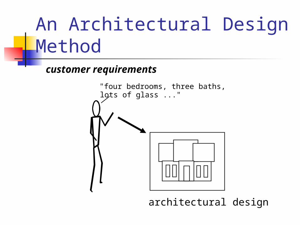
An Architectural Design Method
"four bedrooms, three baths,lots of glass ..."
customer requirements
architectural design
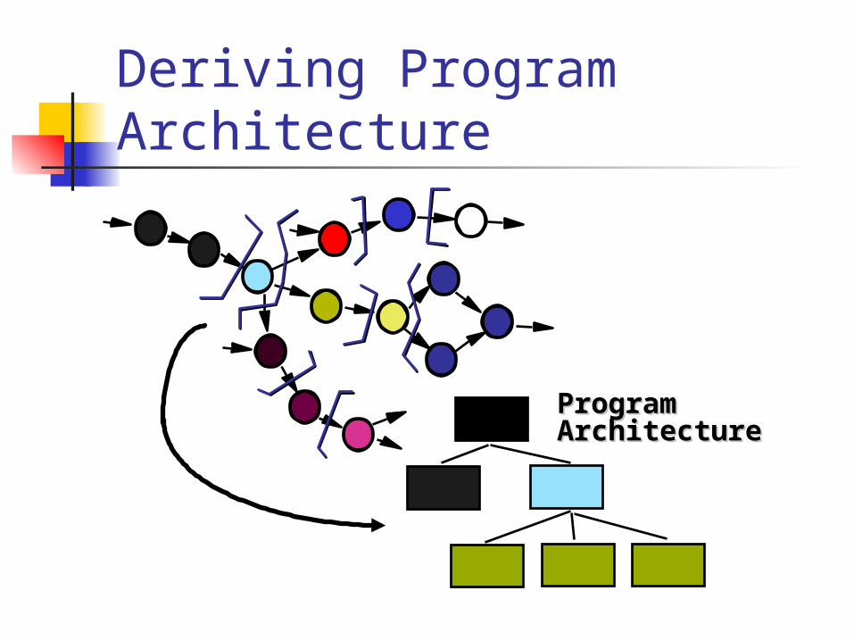
Deriving Program Architecture
ProgramProgramArchitectureArchitecture
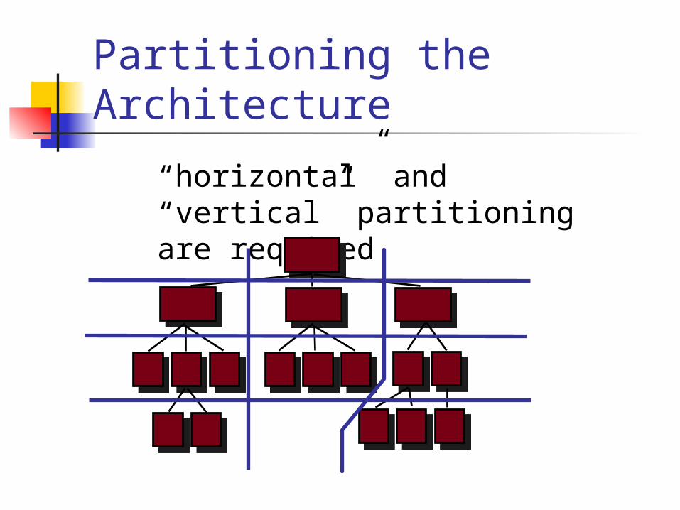
Partitioning the Architecture
“horizontal” and “vertical” partitioning are required
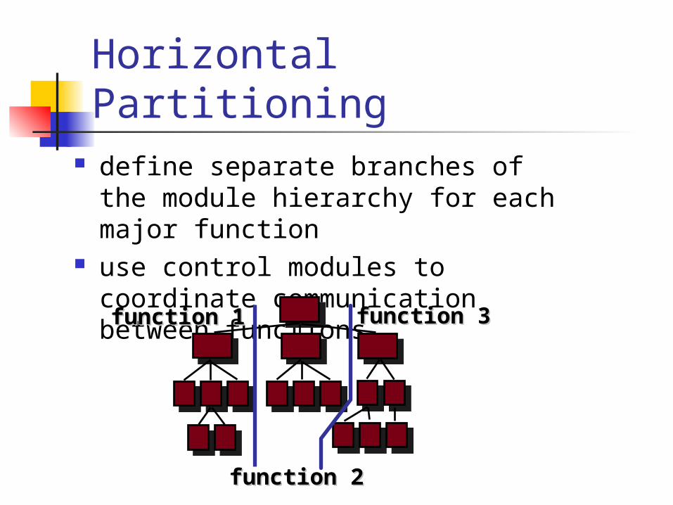
Horizontal Partitioning define separate branches of the
module hierarchy for each major function
use control modules to coordinate communication between functions
function 1function 1 function 3function 3
function 2function 2
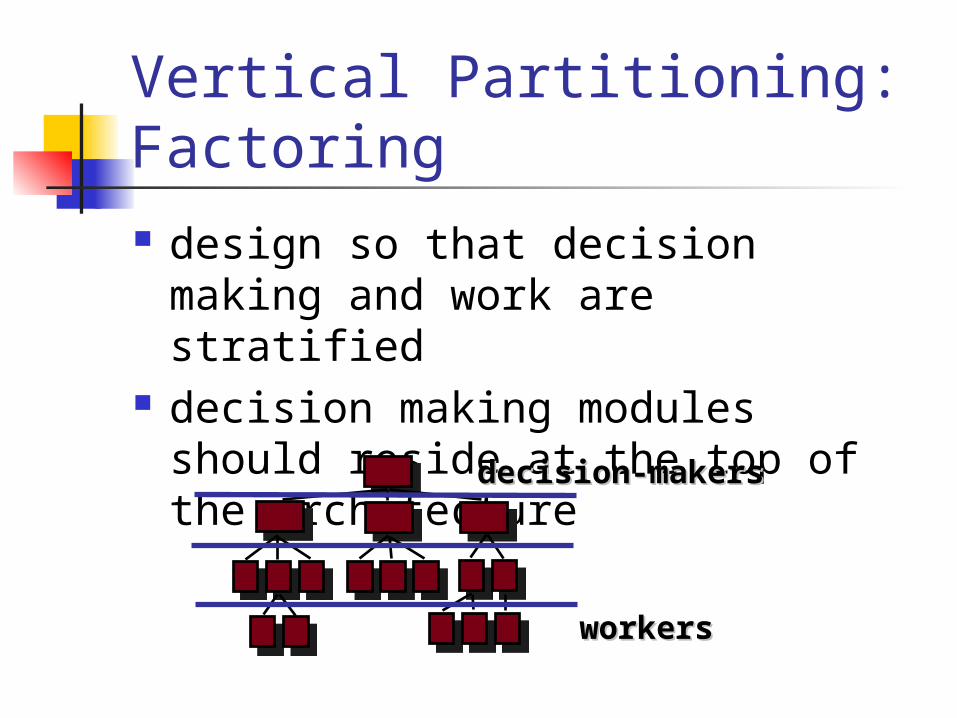
Vertical Partitioning: Factoring design so that decision making and
work are stratified decision making modules should
reside at the top of the architecture
workersworkers
decision-makersdecision-makers
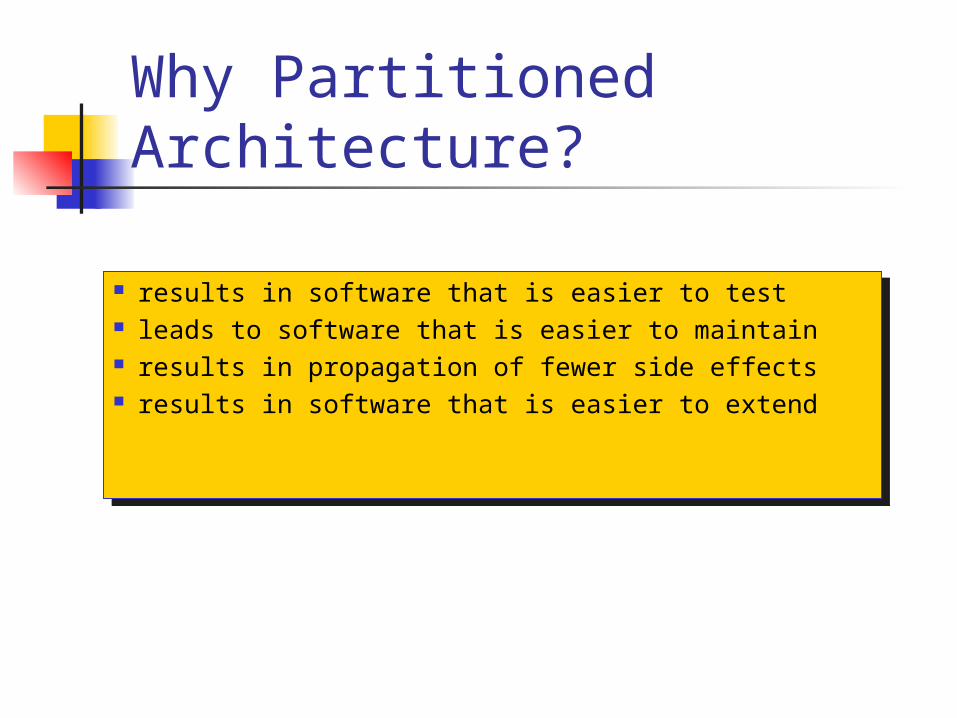
Why Partitioned Architecture?
results in software that is easier to test leads to software that is easier to maintain results in propagation of fewer side effects results in software that is easier to extend
results in software that is easier to test leads to software that is easier to maintain results in propagation of fewer side effects results in software that is easier to extend
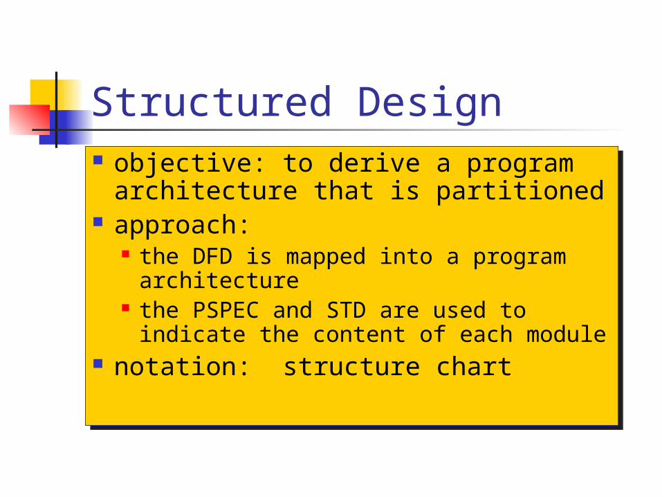
Structured Design objective: to derive a program
architecture that is partitioned approach:
the DFD is mapped into a program architecture
the PSPEC and STD are used to indicate the content of each module
notation: structure chart
objective: to derive a program architecture that is partitioned
approach: the DFD is mapped into a program
architecture the PSPEC and STD are used to
indicate the content of each module notation: structure chart
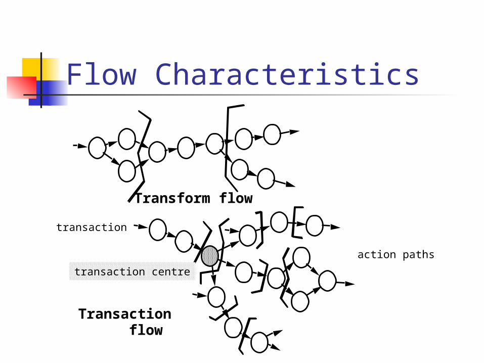
Flow Characteristics
Transform flow
Transactionflow
action paths
transaction
transaction centre
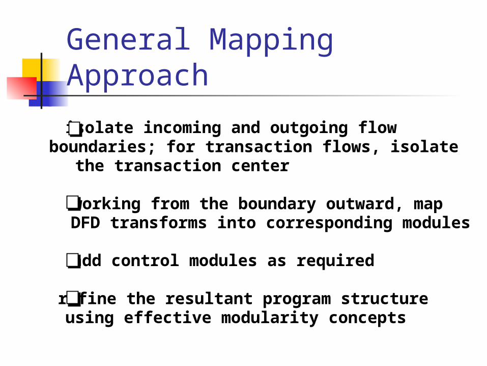
General Mapping Approach
isolate incoming and outgoing flow boundaries; for transaction flows, isolate the transaction center
working from the boundary outward, mapDFD transforms into corresponding modules
add control modules as required
refine the resultant program structureusing effective modularity concepts
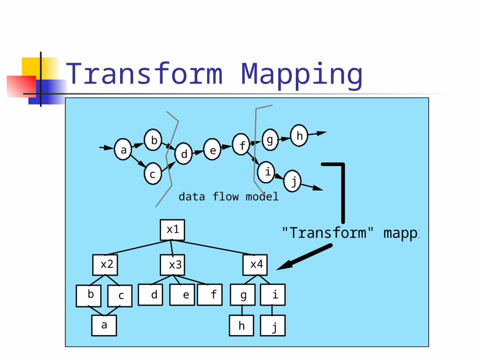
Transform Mapping
data flow model
"Transform" mapping
ab
c
d e fg h
ij
x1
x2 x3 x4
b c
a
d e f g i
h j
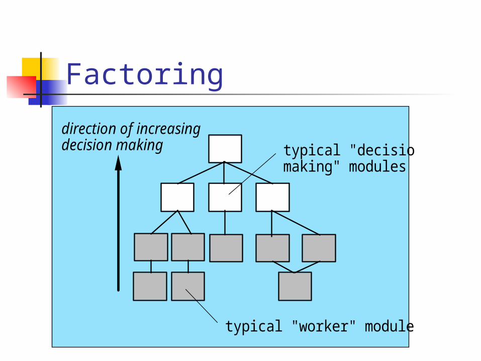
Factoring
typical "worker" modules
typical "decision making" modules
direction of increasing decision making
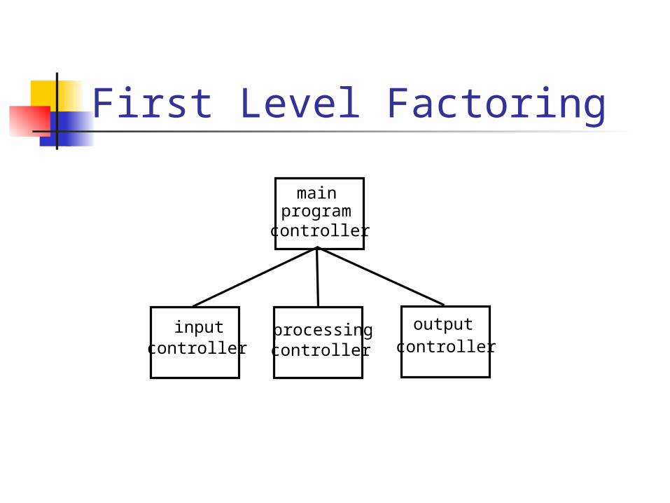
First Level Factoring
main programcontroller
inputcontroller
processingcontroller
outputcontroller
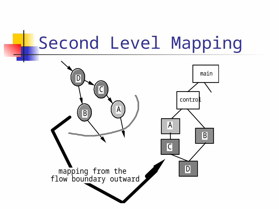
Second Level Mapping
D
C
B A
A
C
B
Dmapping from the flow boundary outward
main
control
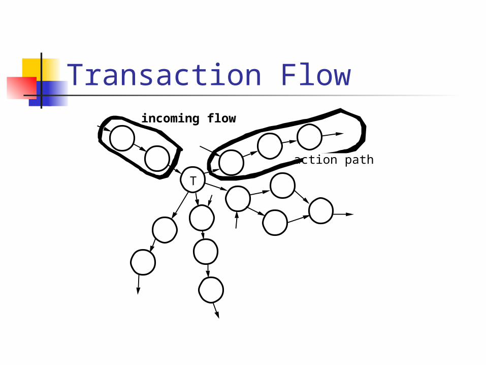
Transaction Flow
T
incoming flow
action path
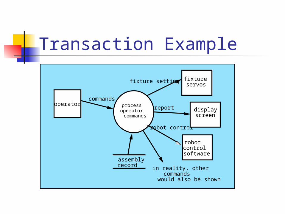
Transaction Example
operatorcommands
processoperator commands
fixture setting
report
robot control
fixtureservos
displayscreen
robotcontrolsoftware
in reality, other commandswould also be shown
assemblyrecord
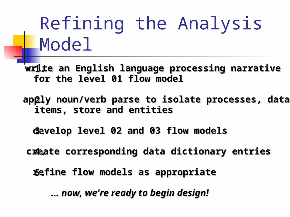
Refining the Analysis Model
write an English language processing narrative write an English language processing narrative for the level 01 flow modelfor the level 01 flow model
apply noun/verb parse to isolate processes, data apply noun/verb parse to isolate processes, data items, store and entitiesitems, store and entities
develop level 02 and 03 flow modelsdevelop level 02 and 03 flow models
create corresponding data dictionary entriescreate corresponding data dictionary entries
refine flow models as appropriaterefine flow models as appropriate
... now, we're ready to begin design!... now, we're ready to begin design!
1.1.
2.2.
3.3.
4.4.
5.5.
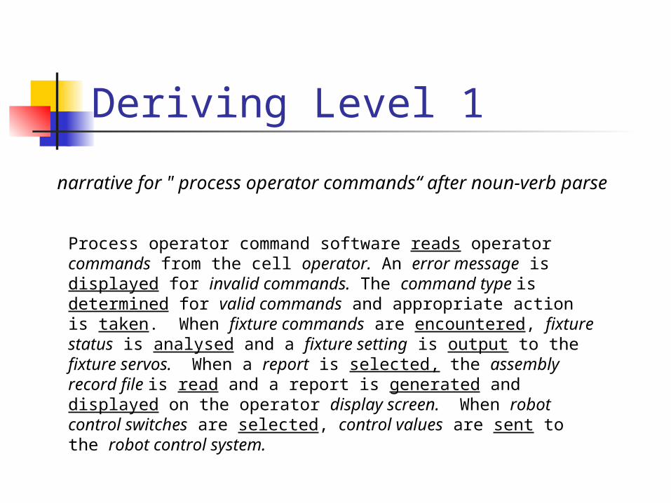
Deriving Level 1
narrative for " process operator commands“ after noun-verb parse
Process operator command software reads operator commands from the cell operator. An error message is displayed for invalid commands. The command type is determined for valid commands and appropriate action is taken. When fixture commands are encountered, fixture status is analysed and a fixture setting is output to the fixture servos. When a report is selected, the assembly record file is read and a report is generated and displayed on the operator display screen. When robot control switches are selected, control values are sent to the robot control system.
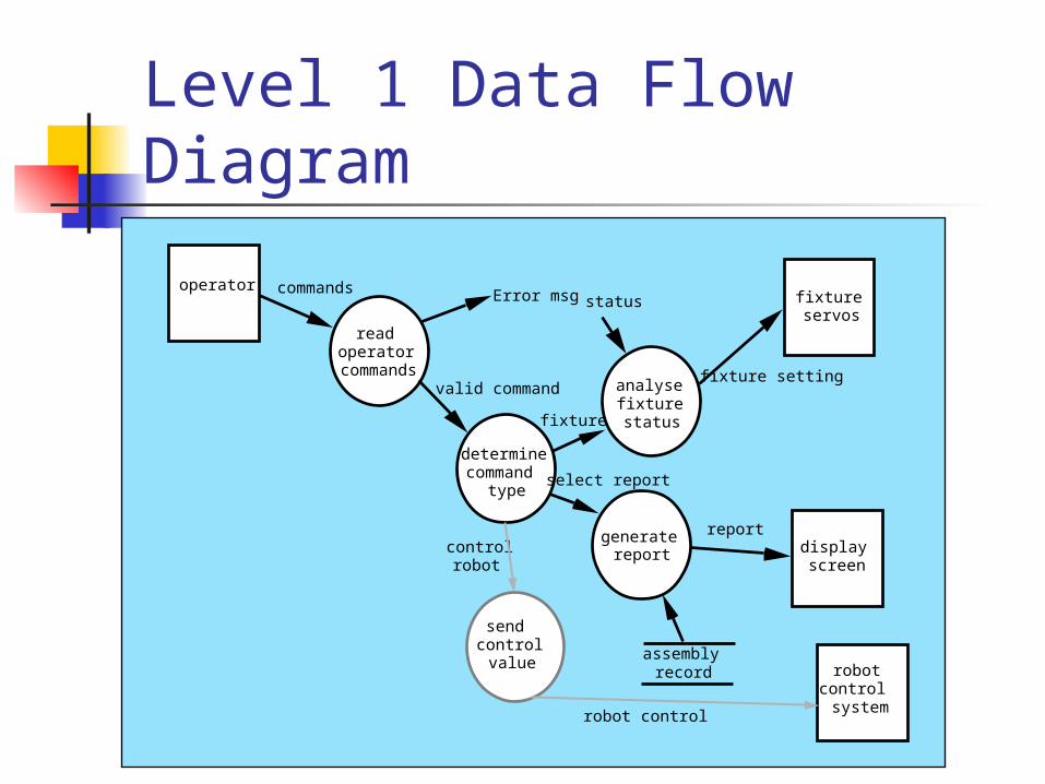
operator commands
read operator
commands
determine command
type
analyse fixture status
generate report
send control value
fixture servos
display screen
robot control system
assembly record
valid command
Error msg
fixture setting
report
robot control
fixture
select report
control robot
status
Level 1 Data Flow Diagram
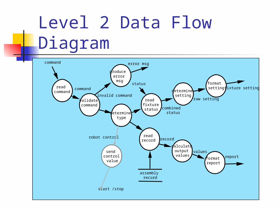
Level 2 Data Flow Diagram
read command
produce error msg
validate command
determine type
read fixture status
determine setting
format setting
read record
calculate output values
format report
reportvalues
record
assembly record
command
command
invalid command
status
error msg
robot control
send control value
start /stop
combined status
raw setting
fixture setting
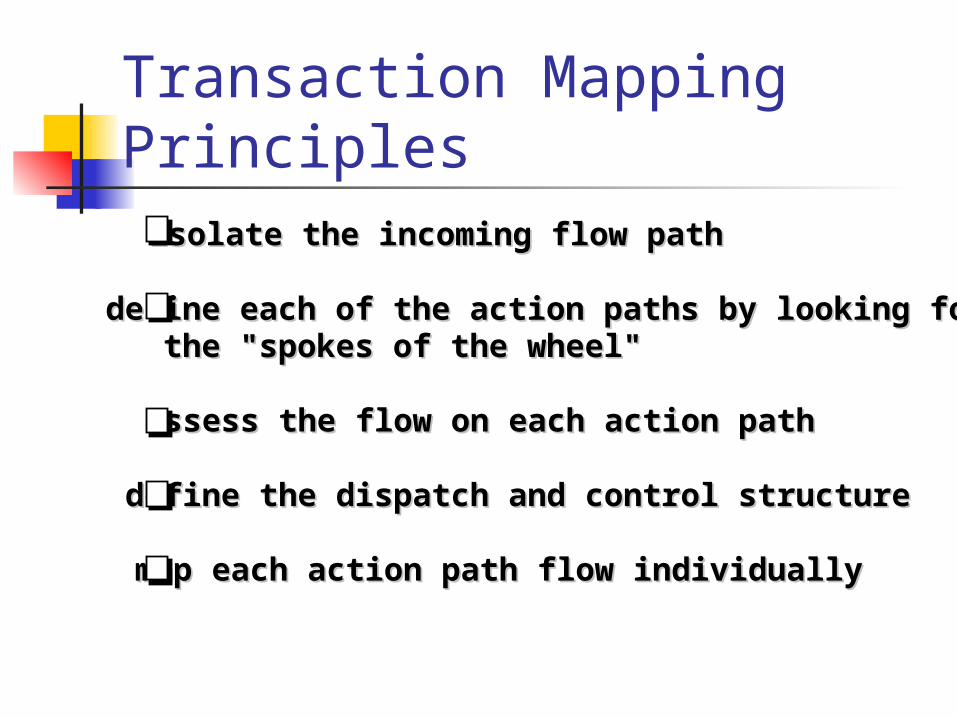
Transaction Mapping Principles
isolate the incoming flow pathisolate the incoming flow path
define each of the action paths by looking for define each of the action paths by looking for the "spokes of the wheel"the "spokes of the wheel"
assess the flow on each action pathassess the flow on each action path
define the dispatch and control structuredefine the dispatch and control structure
map each action path flow individuallymap each action path flow individually
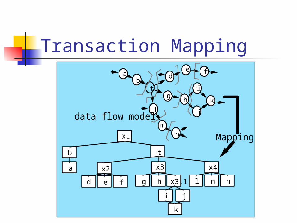
Transaction Mapping
data flow model
ab
t
de f
gh
i
j
kl
mn Mapping
b
a
x1
t
x2
d e f
x3
g h x3.1
i j
k
x4
l m n
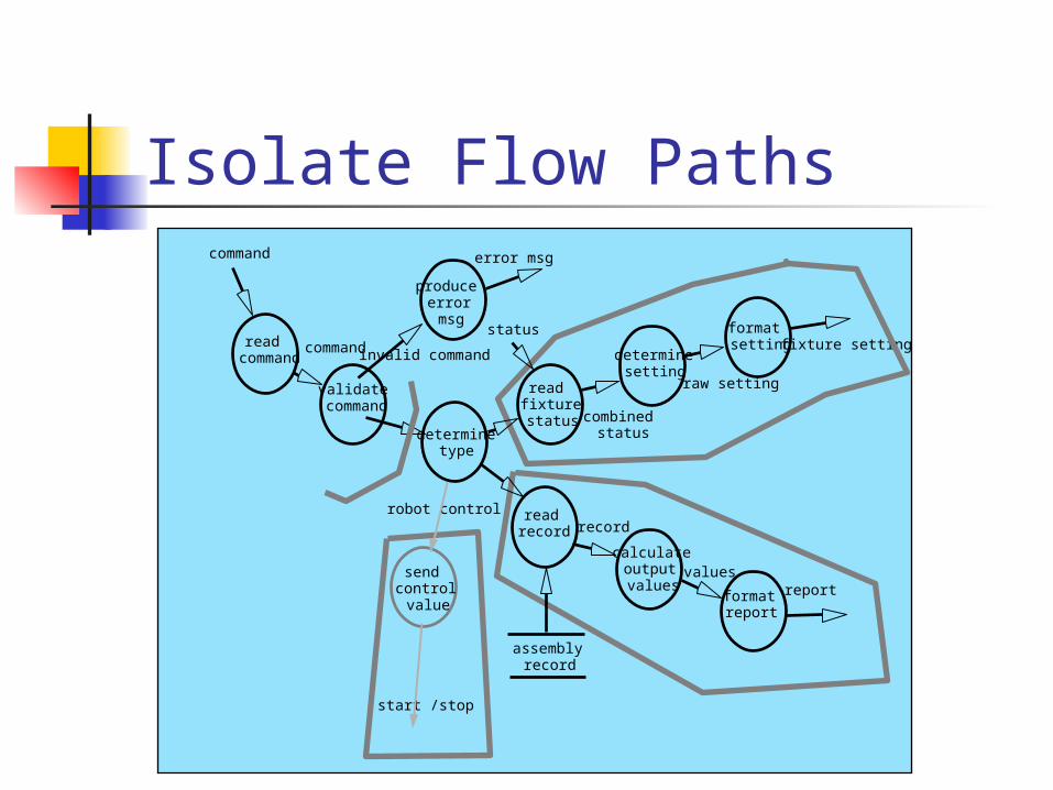
Isolate Flow Paths
read command
produce error msg
validate command
determine type
read fixture status
determine setting
format setting
read record
calculate output values
format report
reportvalues
record
assembly record
command
command invalid command
status
error msg
robot control
send control value
start /stop
combined status
raw setting
fixture setting
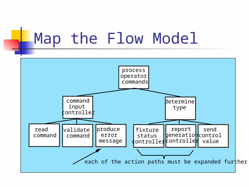
Map the Flow Model
process operator
commands
command input
controller
read command
validate command
produce error
message
determine type
fixture status
controller
report generation controller
send control value
each of the action paths must be expanded further
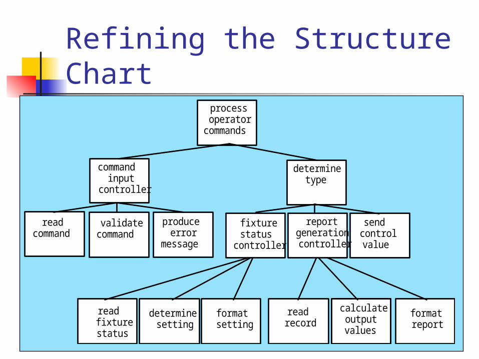
Refining the Structure Chart
process operator
commands
command input
controller
read command
validate command
produce error
message
determine type
send control value
read fixture status
determine setting
format setting
read record
calculate output values
format report
fixture status
controller
report generation controller
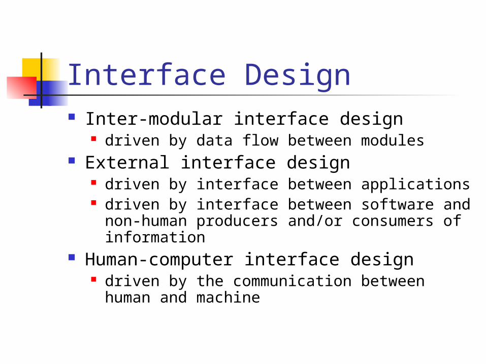
Interface Design Inter-modular interface design
driven by data flow between modules External interface design
driven by interface between applications driven by interface between software and
non-human producers and/or consumers of information
Human-computer interface design driven by the communication between
human and machine
User Interface Design
Interface Design
Easy to use?Easy to use?
Easy to understand?Easy to understand?
Easy to learn?Easy to learn?
Interface Design
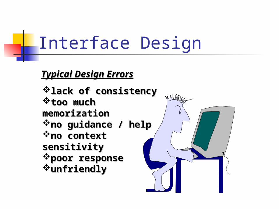
lack of consistencylack of consistencytoo much memorizationtoo much memorizationno guidance / helpno guidance / helpno context sensitivityno context sensitivitypoor responsepoor responseunfriendlyunfriendly
Typical Design ErrorsTypical Design Errors
Golden Rules Place the user in control Reduce the user’s memory load Make the interface consistent
Place the User in Control Define interaction modes in a way that does not
force a user into unnecessary or undesired actions.
Provide for flexible interaction. Allow user interaction to be interruptible and
undoable. Streamline interaction as skill levels advance
and allow the interaction to be customized. Hide technical internals from the casual user. Design for direct interaction with objects that
appear on the screen.
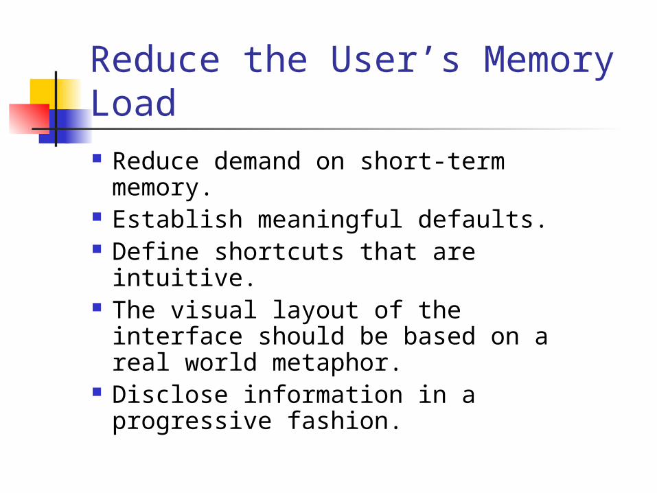
Reduce the User’s Memory Load Reduce demand on short-term
memory. Establish meaningful defaults. Define shortcuts that are intuitive. The visual layout of the interface
should be based on a real world metaphor.
Disclose information in a progressive fashion.
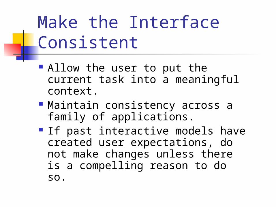
Make the Interface Consistent Allow the user to put the current
task into a meaningful context. Maintain consistency across a
family of applications. If past interactive models have
created user expectations, do not make changes unless there is a compelling reason to do so.
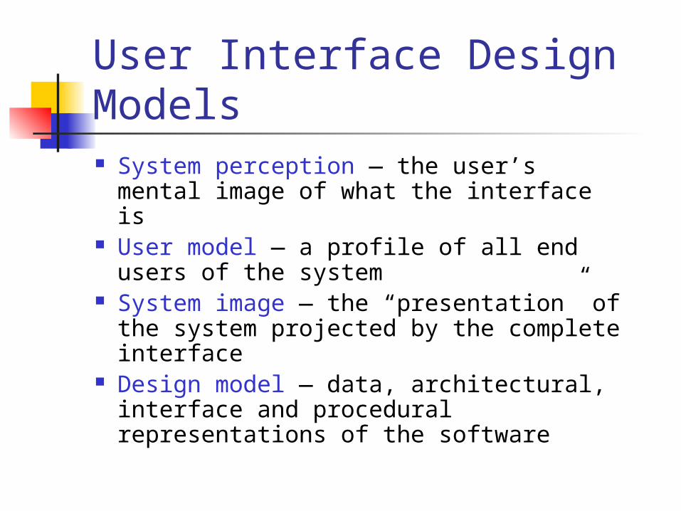
User Interface Design Models System perception — the user’s
mental image of what the interface is User model — a profile of all end
users of the system System image — the “presentation”
of the system projected by the complete interface
Design model — data, architectural, interface and procedural representations of the software
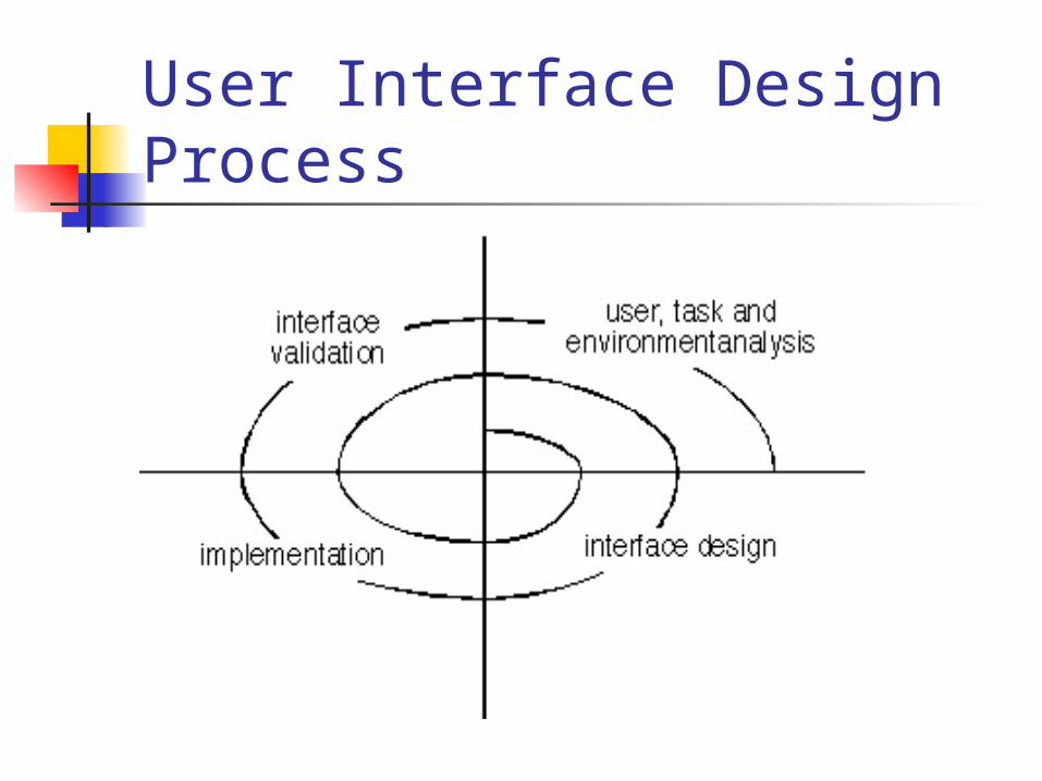
User Interface Design Process
Task Analysis and Modeling All human tasks required to do
the job (of the interface) are defined and classified
Objects (to be manipulated) and actions (functions applied to objects) are identified for each task
Tasks are refined iteratively until the job is completely defined
Interface Design Activities1. Establish the goals and intentions for each task.
2. Map each goal/intention to a sequence of specific actions.
3. Specify the action sequence of tasks and subtasks, also called a user scenario, as it will be executed at the interface level.
4. Indicate the state of the system, i.e., What does the interface look like at the time that a user scenario is performed?
5. Define control mechanisms, i.e., The objects and actions available to the user to alter the system state.
6. Show how control mechanisms affect the state of the system.
7. Indicate how the user interprets the state of the system from information provided through the interface.
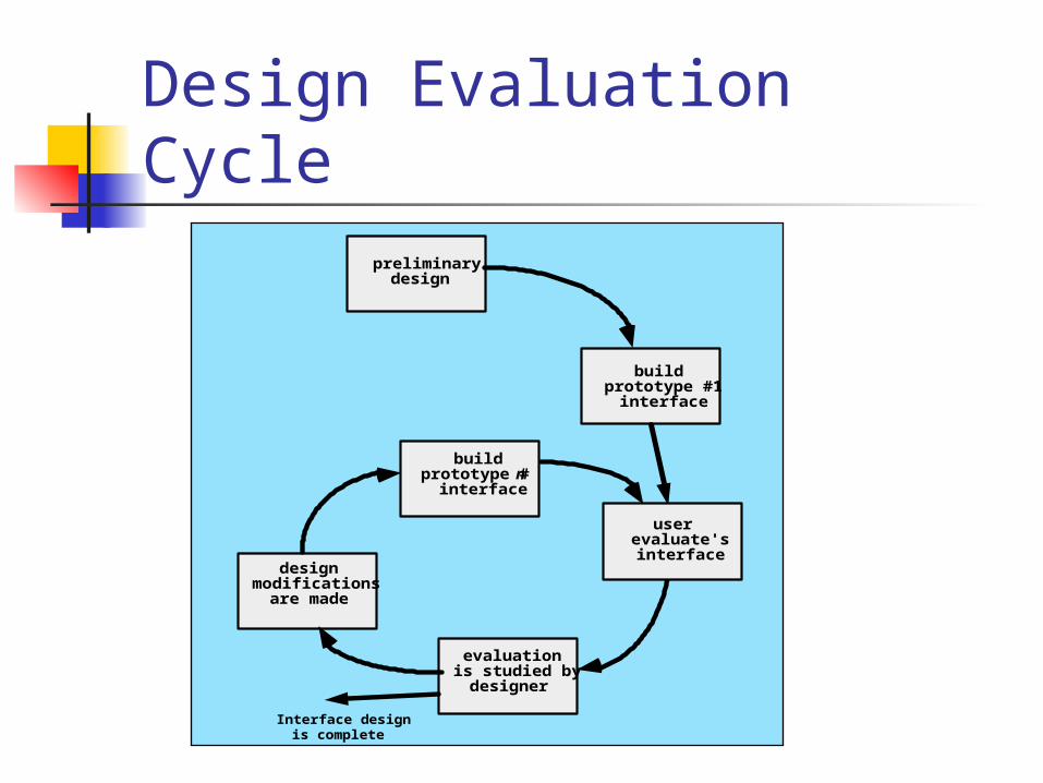
Design Evaluation Cyclepreliminary
design
buildprototype #1
interface
evaluationis studied by
designer
designmodifications
are made
buildprototype # n
interface
userevaluate'sinterface
Interface designis complete