Embed Size (px)
Citation preview
University of Diyala Electrical Circuits Engineering College 2nd Class Electronic Department Year (2015-2016) Lecturer : Wisam N. AL-Obaidi
1
Lecture ( ) Three-Phase Circuits 1) Introduction A single-phase ac power system consists of a generator connected through a pair of wires
(a transmission line) to a load. Fig.1.1 (a) depicts a single-phase twowire system, where Vp
is the rms magnitude of the source voltage and ϕ is the phase. What is more common in
practice is a single-phase threewire system, shown in Fig.1.1 (b). It contains two identical
sources (equal magnitude and the same phase) that are connected to two loads by two
outer wires and the neutral. For example, the normal household system is a single-phase
three-wire system because the terminal voltages have the same magnitude and the same
phase. Such a system allows the connection of both 120-V and 240-V appliances.
Fig.1.1 Single-phase systems: (a) two-wire type, (b) three-wire type.
Circuits or systems in which the ac sources operate at the same frequency but different
phases are known as polyphase.
Fig.1.2 shows a two-phase three-wire system, and Fig.1.3 shows a three-phase fourwire
system.
Fig.1.2 Two-phase three-wire system Fig.1.3 Three-phase four-wire system
University of Diyala Electrical Circuits Engineering College 2nd Class Electronic Department Year (2015-2016) Lecturer : Wisam N. AL-Obaidi
2
A single-phase system, a two-phase system is produced by a generator consisting of two coils
placed perpendicular to each other so that the voltage generated by one lags the other by 900.
A three-phase system is produced by a generator consisting of three sources having the same
amplitude and frequency but out of phase with each other by 1200. Since the three-phase
system is by far the most prevalent and most economical polyphase system.
Three-phase systems are important for at least three reasons:
1) nearly all electric power is generated and distributed in three-phase, at the operating
frequency of 60 Hz (or ω =377 rad/s) or 50 Hz (or ω =314 rad/s). When one-phase or
two-phase inputs are required, they are taken from the three-phase system rather than
generated independently. Even when more than three phases are needed—such as in
the aluminum industry, where 48 phases are required for melting purposes—they can
be provided by manipulating the three phases supplied.
2) the instantaneous power in a three-phase system can be constant (not pulsating. This
results in uniform power transmission and less vibration of three-phase machines.
3) for the same amount of power, the three-phase system is more economical than the
singlephase. The amount of wire required for a three-phase system is less than that
required for an equivalent single-phase system.
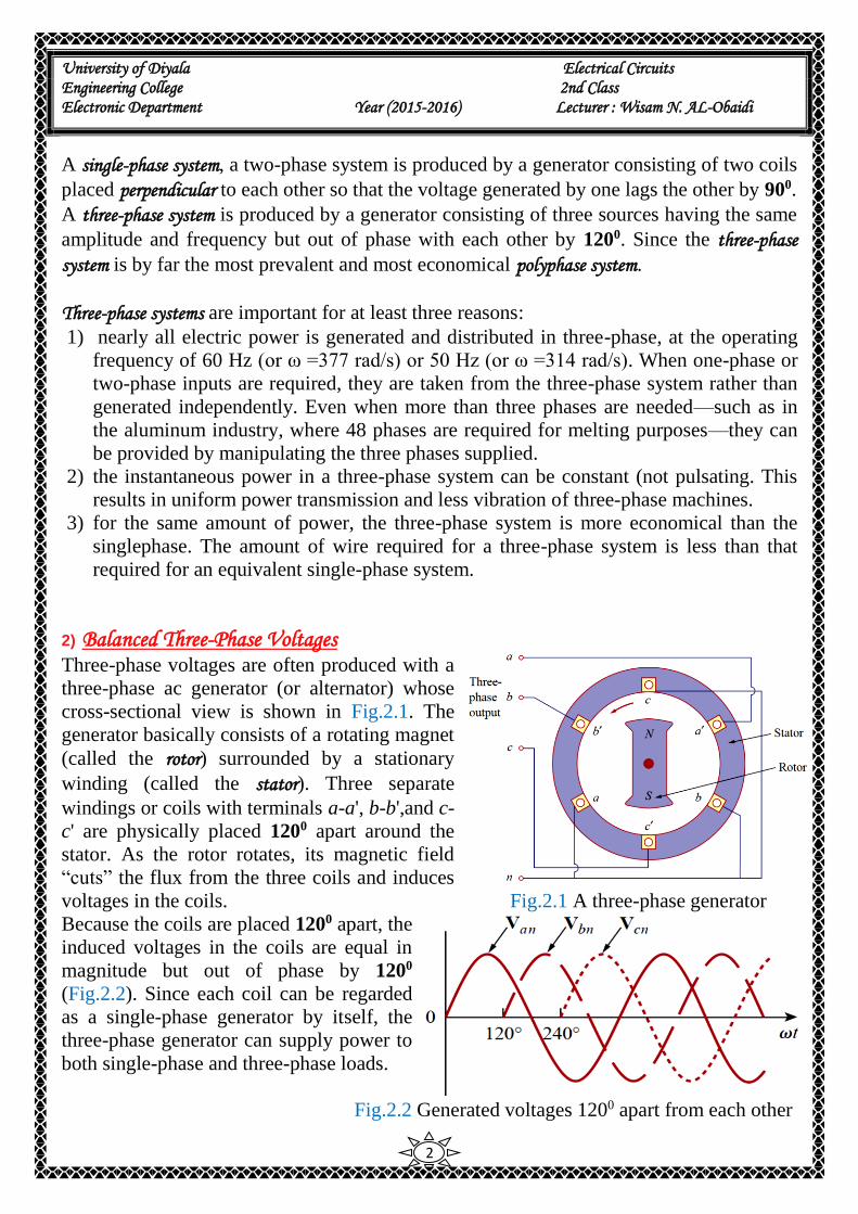
2) Balanced Three-Phase Voltages Three-phase voltages are often produced with a
three-phase ac generator (or alternator) whose
cross-sectional view is shown in Fig.2.1. The
generator basically consists of a rotating magnet
(called the rotor) surrounded by a stationary
winding (called the stator). Three separate
windings or coils with terminals a-a', b-b',and c-
c' are physically placed 1200 apart around the
stator. As the rotor rotates, its magnetic field
“cuts” the flux from the three coils and induces
voltages in the coils. Fig.2.1 A three-phase generator
Because the coils are placed 1200 apart, the
induced voltages in the coils are equal in
magnitude but out of phase by 1200
(Fig.2.2). Since each coil can be regarded
as a single-phase generator by itself, the
three-phase generator can supply power to
both single-phase and three-phase loads.
Fig.2.2 Generated voltages 1200 apart from each other
University of Diyala Electrical Circuits Engineering College 2nd Class Electronic Department Year (2015-2016) Lecturer : Wisam N. AL-Obaidi
3
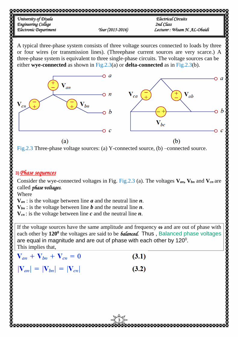
A typical three-phase system consists of three voltage sources connected to loads by three
or four wires (or transmission lines). (Threephase current sources are very scarce.) A
three-phase system is equivalent to three single-phase circuits. The voltage sources can be
either wye-connected as shown in Fig.2.3(a) or delta-connected as in Fig.2.3(b).
Fig.2.3 Three-phase voltage sources: (a) Y-connected source, (b) –connected source.
3) Phase sequences
Consider the wye-connected voltages in Fig. Fig.2.3 (a). The voltages Van, Vbn and Vcn are
called phase voltages.
Where
Van : is the voltage between line a and the neutral line n.
Vbn : is the voltage between line b and the neutral line n.
Vcn : is the voltage between line c and the neutral line n.
If the voltage sources have the same amplitude and frequency ω and are out of phase with
each other by 1200 the voltages are said to be balanced. Thus , Balanced phase voltages
are equal in magnitude and are out of phase with each other by 1200.
This implies that,

University of Diyala Electrical Circuits Engineering College 2nd Class Electronic Department Year (2015-2016) Lecturer : Wisam N. AL-Obaidi
4
Since the three-phase voltages are 1200 out of phase with each other, there are two
possible combinations. One is shown in Fig.3.1(a) and
known as the abc sequence or positive sequence. This
sequence is produced when the rotor in Fig.2.1 rotates
counterclockwise direction.
where Vp is the effective or rms value of the phase
voltages.
The other is shown in Fig.3.1(b) and known as the acb
sequence or negative sequence. This sequence is produced
when the rotor in Fig.2.1 rotates clockwise direction.
Fig.3.1Phase sequences: (a) abc or positive
sequence, (b) acb or negative sequence.
The phase sequence is the time order in which the voltages pass through their respective maximum values.
University of Diyala Electrical Circuits Engineering College 2nd Class Electronic Department Year (2015-2016) Lecturer : Wisam N. AL-Obaidi
5
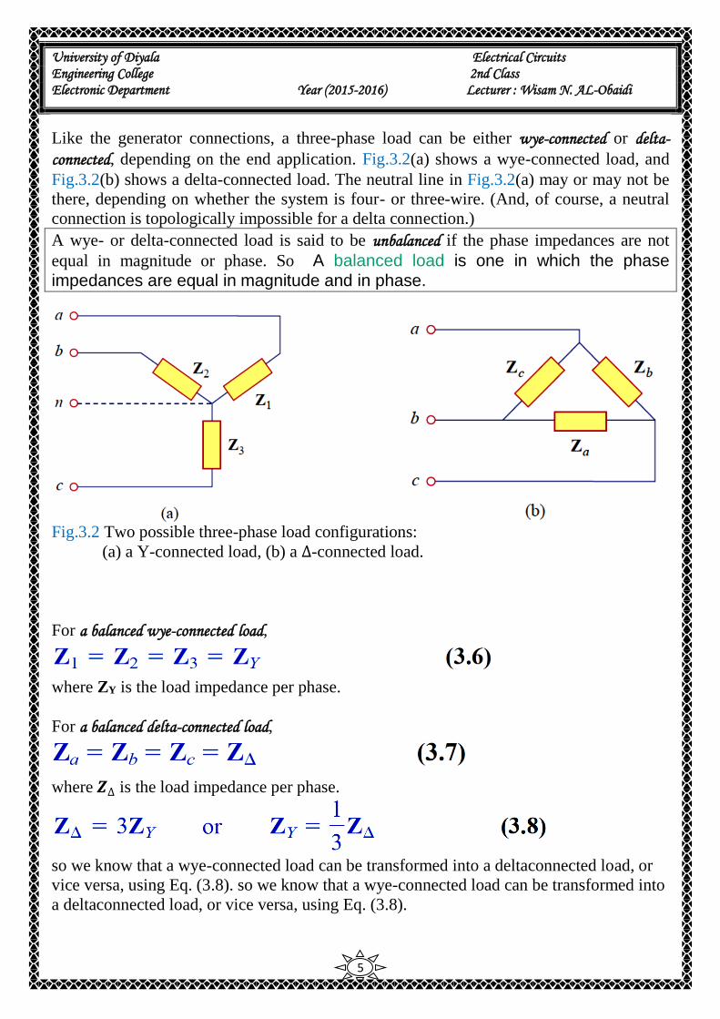
Like the generator connections, a three-phase load can be either wye-connected or delta-
connected, depending on the end application. Fig.3.2(a) shows a wye-connected load, and
Fig.3.2(b) shows a delta-connected load. The neutral line in Fig.3.2(a) may or may not be
there, depending on whether the system is four- or three-wire. (And, of course, a neutral
connection is topologically impossible for a delta connection.)
A wye- or delta-connected load is said to be unbalanced if the phase impedances are not
equal in magnitude or phase. So A balanced load is one in which the phase impedances are equal in magnitude and in phase.
Fig.3.2 Two possible three-phase load configurations:
(a) a Y-connected load, (b) a ∆-connected load.
For a balanced wye-connected load,
where ZY is the load impedance per phase.
For a balanced delta-connected load,
where 𝒁∆ is the load impedance per phase.
so we know that a wye-connected load can be transformed into a deltaconnected load, or
vice versa, using Eq. (3.8). so we know that a wye-connected load can be transformed into
a deltaconnected load, or vice versa, using Eq. (3.8).
University of Diyala Electrical Circuits Engineering College 2nd Class Electronic Department Year (2015-2016) Lecturer : Wisam N. AL-Obaidi
6
It is appropriate to mention here that a balanced delta-connected load is more common
than a balanced wye-connected load. This is due to the ease with which loads may be
added or removed from each phase of a delta-connected load. This is very difficult with a
wye-connected load because the neutral may not be accessible. On the other hand, delta-
connected sources are not common in practice because of the circulating current that will
result in the delta-mesh if the three-phase voltages are slightly unbalanced.
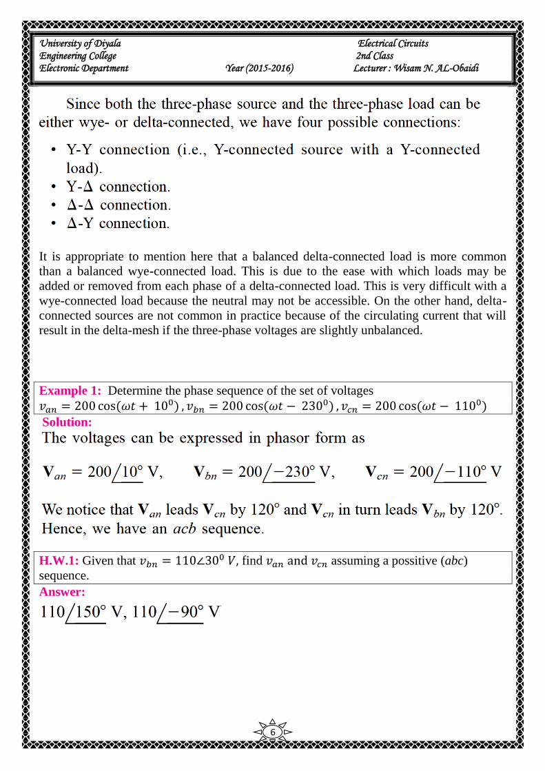
Example 1: Determine the phase sequence of the set of voltages 𝑣𝑎𝑛 = 200 cos(𝜔𝑡 + 10
0) , 𝑣𝑏𝑛 = 200 cos(𝜔𝑡 − 2300) , 𝑣𝑐𝑛 = 200 cos(𝜔𝑡 − 1100)
Solution:
H.W.1: Given that 𝑣𝑏𝑛 = 110∠300 𝑉, find 𝑣𝑎𝑛 and 𝑣𝑐𝑛 assuming a possitive (abc)
sequence.
Answer:
University of Diyala Electrical Circuits Engineering College 2nd Class Electronic Department Year (2015-2016) Lecturer : Wisam N. AL-Obaidi
7
3.1) Balanced Wye-Wye Connection
We begin with the Y-Y system, because any balanced three-phase system can be reduced
to an equivalent Y-Y system. Therefore, analysis of this system should be regarded as the
key to solving all balanced three-phase systems.
A balanced Y-Y system is a three-phase system with a balanced Y-connected source and a balanced Y-connected load.
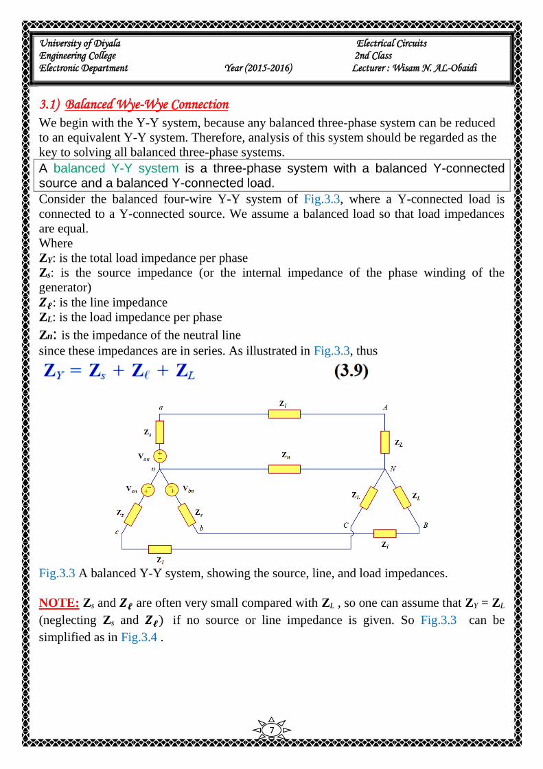
Consider the balanced four-wire Y-Y system of Fig.3.3, where a Y-connected load is
connected to a Y-connected source. We assume a balanced load so that load impedances
are equal.
Where
ZY: is the total load impedance per phase
Zs: is the source impedance (or the internal impedance of the phase winding of the
generator)
𝒁𝓵: is the line impedance
ZL: is the load impedance per phase
Zn: is the impedance of the neutral line since these impedances are in series. As illustrated in Fig.3.3, thus
Fig.3.3 A balanced Y-Y system, showing the source, line, and load impedances.
NOTE: Zs and 𝒁𝓵 are often very small compared with ZL , so one can assume that ZY = ZL
(neglecting Zs and 𝒁𝓵) if no source or line impedance is given. So Fig.3.3 can be
simplified as in Fig.3.4 .

University of Diyala Electrical Circuits Engineering College 2nd Class Electronic Department Year (2015-2016) Lecturer : Wisam N. AL-Obaidi
8
Fig.3.4 A balanced Y-Y connection.
For positive sequence, the phase voltages (or line-toneutral voltages) are
𝑉𝑎𝑛 = 𝑉𝑝∠00
𝑉𝑏𝑛 = 𝑉𝑝∠−1200
𝑉𝑐𝑛 = 𝑉𝑝∠+1200
(𝟑. 𝟏𝟎)
The line-to-line voltages or simply line voltages Vab, Vbc, and Vca are related to the phase
voltages. For example
𝑉𝑎𝑏 = 𝑉𝑎𝑛 + 𝑉𝑛𝑏 = 𝑉𝑎𝑛 − 𝑉𝑏𝑛 = 𝑉𝑝∠00 − 𝑉𝑝∠−120
0
= 𝑉𝑝 (1 +1
2+ 𝑗
√3
2) = √3 𝑉𝑝∠30
0 (3.11a)
Similarly,
𝑉𝑏𝑐 = 𝑉𝑏𝑛 − 𝑉𝑐𝑛 = √3 𝑉𝑝∠ − 900 (3.11b)
𝑉𝑐𝑎 = 𝑉𝑐𝑛 − 𝑉𝑎𝑛 = √3 𝑉𝑝∠ − 2100 (3.11c)
Thus, the magnitude of the line voltages 𝑉𝐿 is √3 times the magnitude of the phase
voltages 𝑉𝑝 or
𝑉𝐿 = √3 𝑉𝑝 (3.12)
Where
𝑉𝑝 = |𝑉𝑎𝑛| = |𝑉𝑏𝑛| = |𝑉𝑐𝑛| (3.13)
𝑉𝐿 = |𝑉𝑎𝑏| = |𝑉𝑏𝑐| = |𝑉𝑐𝑎| (3.14)
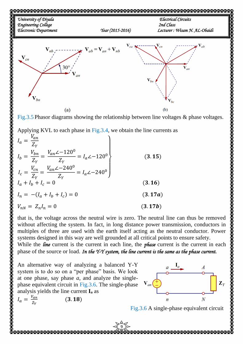
Also the line voltages lead their corresponding phase voltages by 300 as illustrated in
Fig.3.5 (a) which also shows how to determine 𝑉𝑎𝑏 from the phase voltages, while Fig.3.5
(b) shows the same for the three line voltages. Notice that 𝑉𝑎𝑏 leads 𝑉𝑏𝑐 by 1200 and leads
𝑉𝑐𝑎 by 1200 so that the line voltages sum up to zero as do the phase voltages.
University of Diyala Electrical Circuits Engineering College 2nd Class Electronic Department Year (2015-2016) Lecturer : Wisam N. AL-Obaidi
9
Fig.3.5 Phasor diagrams showing the relationship between line voltages & phase voltages.
Applying KVL to each phase in Fig.3.4, we obtain the line currents as
𝐼𝑎 = 𝑉𝑎𝑛𝑍𝑌
𝐼𝑏 = 𝑉𝑏𝑛𝑍𝑌
= 𝑉𝑎𝑛∠−120
0
𝑍𝑌= 𝐼𝑎∠−120
0
𝐼𝑐 = 𝑉𝑐𝑛𝑍𝑌
= 𝑉𝑎𝑛∠−240
0
𝑍𝑌= 𝐼𝑎∠−240
0
(𝟑. 𝟏𝟓)
𝐼𝑎 + 𝐼𝑏 + 𝐼𝑐 = 0 (𝟑. 𝟏𝟔)
𝐼𝑛 = −(𝐼𝑎 + 𝐼𝑏 + 𝐼𝑐) = 0 (𝟑. 𝟏𝟕𝒂)
𝑉𝑛𝑁 = 𝑍𝑛𝐼𝑛 = 0 (𝟑. 𝟏𝟕𝒃)
that is, the voltage across the neutral wire is zero. The neutral line can thus be removed
without affecting the system. In fact, in long distance power transmission, conductors in
multiples of three are used with the earth itself acting as the neutral conductor. Power
systems designed in this way are well grounded at all critical points to ensure safety.
While the line current is the current in each line, the phase current is the current in each
phase of the source or load. In the Y-Y system, the line current is the same as the phase current.
An alternative way of analyzing a balanced Y-Y
system is to do so on a “per phase” basis. We look
at one phase, say phase a, and analyze the single-
phase equivalent circuit in Fig.3.6. The single-phase
analysis yields the line current Ia as
𝐼𝑎 = 𝑉𝑎𝑛
𝑍𝑌 (𝟑. 𝟏𝟖)
Fig.3.6 A single-phase equivalent circuit
University of Diyala Electrical Circuits Engineering College 2nd Class Electronic Department Year (2015-2016) Lecturer : Wisam N. AL-Obaidi
10
From Ia we use the phase sequence to obtain other line currents. Thus, as long as the
system is balanced, we need only analyze one phase. We may do this even if the neutral
line is absent, as in the three-wire system.
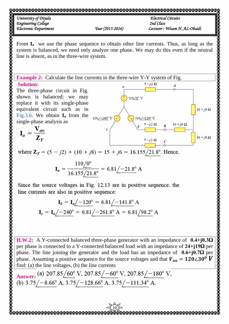
Example 2: Calculate the line currents in the three-wire Y-Y system of Fig. Solution:
The three-phase circuit in Fig.
shown is balanced; we may
replace it with its single-phase
equivalent circuit such as in
Fig.3.6. We obtain Ia from the
single-phase analysis as
H.W.2: A Y-connected balanced three-phase generator with an impedance of 0.4+j0.3Ω
per phase is connected to a Y-connected balanced load with an impedance of 24+j19Ω per
phase. The line joining the generator and the load has an impedance of 0.6+j0.7Ω per
phase. Assuming a positive sequence for the source voltages and that 𝑽𝒂𝒏 = 𝟏𝟐𝟎∠𝟑𝟎𝟎 𝑽
find: (a) the line voltages, (b) the line currents
Answer:
University of Diyala Electrical Circuits Engineering College 2nd Class Electronic Department Year (2015-2016) Lecturer : Wisam N. AL-Obaidi
11
3.2) Balanced Wye-Delta Connection
A balanced Y- ∆ system consists of a balanced Y-connected source feeding a balanced ∆-connected load.
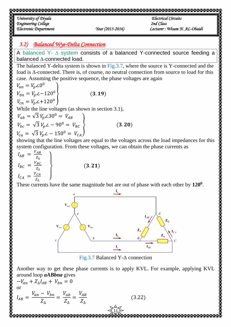
The balanced Y-delta system is shown in Fig.3.7, where the source is Y-connected and the
load is ∆-connected. There is, of course, no neutral connection from source to load for this
case. Assuming the positive sequence, the phase voltages are again
𝑉𝑎𝑛 = 𝑉𝑝∠00
𝑉𝑏𝑛 = 𝑉𝑝∠−1200
𝑉𝑐𝑛 = 𝑉𝑝∠+1200
(𝟑. 𝟏𝟗)
While the line voltages (as shown in section 3.1),
𝑉𝑎𝑏 = √3 𝑉𝑝∠300 = 𝑉𝐴𝐵
𝑉𝑏𝑐 = √3 𝑉𝑝∠ − 900 = 𝑉𝐵𝐶
𝑉𝑐𝑎 = √3 𝑉𝑝∠ − 1500 = 𝑉𝐶𝐴
(𝟑. 𝟐𝟎)
showing that the line voltages are equal to the voltages across the load impedances for this
system configuration. From these voltages, we can obtain the phase currents as
𝐼𝐴𝐵 = 𝑉𝐴𝐵
𝑍∆
𝐼𝐵𝐶 = 𝑉𝐵𝐶
𝑍∆
𝐼𝐶𝐴 = 𝑉𝐶𝐴
𝑍∆
(𝟑. 𝟐𝟏)
These currents have the same magnitude but are out of phase with each other by 1200.
Fig.3.7 Balanced Y-∆ connection
Another way to get these phase currents is to apply KVL. For example, applying KVL
around loop aABbna gives
−𝑉𝑎𝑛 + 𝑍∆𝐼𝐴𝐵 + 𝑉𝑏𝑛 = 0 or
𝐼𝐴𝐵 = 𝑉𝑎𝑛 − 𝑉𝑏𝑛
𝑍∆= 𝑉𝑎𝑏𝑍∆
= 𝑉𝐴𝐵𝑍∆ (3.22)
University of Diyala Electrical Circuits Engineering College 2nd Class Electronic Department Year (2015-2016) Lecturer : Wisam N. AL-Obaidi
12
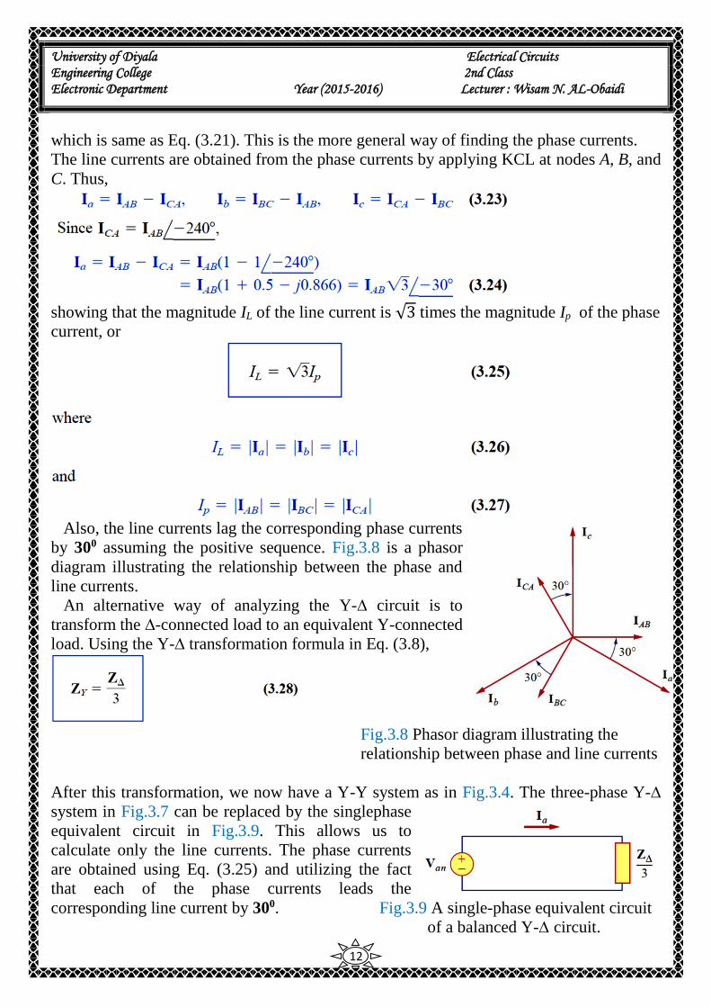
which is same as Eq. (3.21). This is the more general way of finding the phase currents.
The line currents are obtained from the phase currents by applying KCL at nodes A, B, and
C. Thus,
showing that the magnitude IL of the line current is √3 times the magnitude Ip of the phase
current, or
Also, the line currents lag the corresponding phase currents
by 300 assuming the positive sequence. Fig.3.8 is a phasor
diagram illustrating the relationship between the phase and
line currents.
An alternative way of analyzing the Y-∆ circuit is to
transform the ∆-connected load to an equivalent Y-connected
load. Using the Y-∆ transformation formula in Eq. (3.8),
Fig.3.8 Phasor diagram illustrating the
relationship between phase and line currents
After this transformation, we now have a Y-Y system as in Fig.3.4. The three-phase Y-∆
system in Fig.3.7 can be replaced by the singlephase
equivalent circuit in Fig.3.9. This allows us to
calculate only the line currents. The phase currents
are obtained using Eq. (3.25) and utilizing the fact
that each of the phase currents leads the
corresponding line current by 300. Fig.3.9 A single-phase equivalent circuit
of a balanced Y-∆ circuit.

University of Diyala Electrical Circuits Engineering College 2nd Class Electronic Department Year (2015-2016) Lecturer : Wisam N. AL-Obaidi
13
Example 3: A balanced abc-sequence Y-connected source with Van = 𝟏𝟎𝟎∠ 𝟏𝟎𝟎 𝐕 is
connected to a ∆-connected balanced load (8+j4)Ω per phase. Calculate the phase and line
currents.
Solution: This can be resolved in two ways,
H.W.3: One line voltage of a balanced Y-connected source is 𝑽𝑨𝑩 = 𝟐𝟒𝟎∠−𝟐𝟎𝟎 𝑽 . If
the source is connected to a ∆-connected load of 𝟐𝟎∠𝟒𝟎𝟎Ω, find the phase and line
currents. Assume the abc sequence.
Answer:
University of Diyala Electrical Circuits Engineering College 2nd Class Electronic Department Year (2015-2016) Lecturer : Wisam N. AL-Obaidi
14
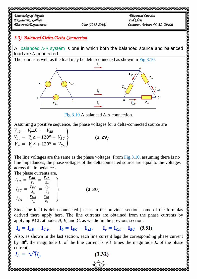
3.3) Balanced Delta-Delta Connection
A balanced ∆-∆ system is one in which both the balanced source and balanced load are ∆-connected.
The source as well as the load may be delta-connected as shown in Fig.3.10.
Fig.3.10 A balanced ∆-∆ connection.
Assuming a positive sequence, the phase voltages for a delta-connected source are
𝑉𝑎𝑏 = 𝑉𝑝∠00 = 𝑉𝐴𝐵
𝑉𝑏𝑐 = 𝑉𝑝∠ − 1200 = 𝑉𝐵𝐶
𝑉𝑐𝑎 = 𝑉𝑝∠ + 1200 = 𝑉𝐶𝐴
(𝟑. 𝟐𝟗)
The line voltages are the same as the phase voltages. From Fig.3.10, assuming there is no
line impedances, the phase voltages of the deltaconnected source are equal to the voltages
across the impedances.
The phase currents are,
𝐼𝐴𝐵 = 𝑉𝐴𝐵
𝑍∆ =
𝑉𝑎𝑏
𝑍∆
𝐼𝐵𝐶 = 𝑉𝐵𝐶
𝑍∆ =
𝑉𝑏𝑐
𝑍∆
𝐼𝐶𝐴 = 𝑉𝐶𝐴
𝑍∆ =
𝑉𝑐𝑎
𝑍∆
(𝟑. 𝟑𝟎)
Since the load is delta-connected just as in the previous section, some of the formulas
derived there apply here. The line currents are obtained from the phase currents by
applying KCL at nodes A, B, and C, as we did in the previous section:
Also, as shown in the last section, each line current lags the corresponding phase current
by 300; the magnitude IL of the line current is √3 times the magnitude In of the phase
current,

University of Diyala Electrical Circuits Engineering College 2nd Class Electronic Department Year (2015-2016) Lecturer : Wisam N. AL-Obaidi
15
An alternative way of analyzing the ∆-∆ circuit is to convert both the source and the load
to their Y equivalents. We already know that 𝒁𝒀 = 𝒁∆
𝟑 . To convert a ∆-connected source
to a Y-connected source, see the next section.
Example 4: A balanced ∆-connected load having an impedance (20 – j15) Ω is
connected to a ∆-connected, positive-sequence generator having Vab =
𝟑𝟑𝟎∠ 𝟎𝟎 𝐕 .Calculate the phase currents of the load and the line currents.
Solution:
H.W.4: A positive-sequence, balanced ∆-connected source supplies a balanced ∆-
connected load. If the impedance per phase of the load is (18 + j12) Ω and 𝑰𝒂 =𝟏𝟗. 𝟐𝟎𝟐∠𝟑𝟓𝟎 𝐴. Find 𝑰𝑨𝑩 and 𝑽𝑨𝑩
Answer:
University of Diyala Electrical Circuits Engineering College 2nd Class Electronic Department Year (2015-2016) Lecturer : Wisam N. AL-Obaidi
16
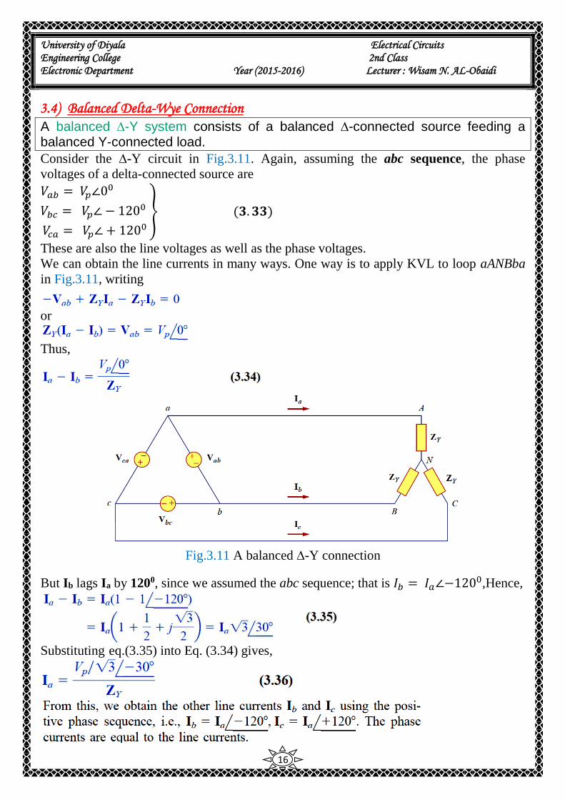
3.4) Balanced Delta-Wye Connection
A balanced ∆-Y system consists of a balanced ∆-connected source feeding a balanced Y-connected load.
Consider the ∆-Y circuit in Fig.3.11. Again, assuming the abc sequence, the phase
voltages of a delta-connected source are
𝑉𝑎𝑏 = 𝑉𝑝∠00
𝑉𝑏𝑐 = 𝑉𝑝∠ − 1200
𝑉𝑐𝑎 = 𝑉𝑝∠ + 1200
(𝟑. 𝟑𝟑)
These are also the line voltages as well as the phase voltages.
We can obtain the line currents in many ways. One way is to apply KVL to loop aANBba
in Fig.3.11, writing
or
Thus,
Fig.3.11 A balanced ∆-Y connection
But Ib lags Ia by 1200, since we assumed the abc sequence; that is 𝐼𝑏 = 𝐼𝑎∠−1200,Hence,
Substituting eq.(3.35) into Eq. (3.34) gives,
University of Diyala Electrical Circuits Engineering College 2nd Class Electronic Department Year (2015-2016) Lecturer : Wisam N. AL-Obaidi
17
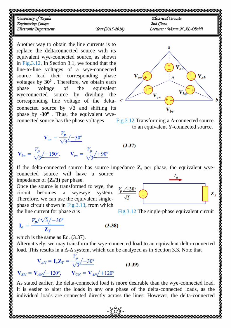
Another way to obtain the line currents is to
replace the deltaconnected source with its
equivalent wye-connected source, as shown
in Fig.3.12. In Section 3.1, we found that the
line-to-line voltages of a wye-connected
source lead their corresponding phase
voltages by 300 . Therefore, we obtain each
phase voltage of the equivalent
wyeconnected source by dividing the
corresponding line voltage of the delta-
connected source by √3 and shifting its
phase by -300 . Thus, the equivalent wye-
connected source has the phase voltages Fig.3.12 Transforming a ∆-connected source
to an equivalent Y-connected source.
If the delta-connected source has source impedance Zs per phase, the equivalent wye-
connected source will have a source
impedance of (Zs/3) per phase.
Once the source is transformed to wye, the
circuit becomes a wyewye system.
Therefore, we can use the equivalent single-
phase circuit shown in Fig.3.13, from which
the line current for phase a is Fig.3.12 The single-phase equivalent circuit
which is the same as Eq. (3.37).
Alternatively, we may transform the wye-connected load to an equivalent delta-connected
load. This results in a ∆-∆ system, which can be analyzed as in Section 3.3. Note that
As stated earlier, the delta-connected load is more desirable than the wye-connected load.
It is easier to alter the loads in any one phase of the delta-connected loads, as the
individual loads are connected directly across the lines. However, the delta-connected

University of Diyala Electrical Circuits Engineering College 2nd Class Electronic Department Year (2015-2016) Lecturer : Wisam N. AL-Obaidi
18
source is hardly used in practice, because any slight imbalance in the phase voltages will
result in unwanted circulating currents.
Table 3.1 presents a summary of the formulas for phase currents and voltages and line
currents and voltages for the four connections. Students are advised not to memorize the
formulas but to understand how they are derived. The formulas can always be
University of Diyala Electrical Circuits Engineering College 2nd Class Electronic Department Year (2015-2016) Lecturer : Wisam N. AL-Obaidi
19
Example 5: A balanced Y-connected load with a phase impedance of (40 + j25) Ω is
supplied by a balanced, positive sequence ∆-connected source with a line voltage of 210
V. Calculate the phase currents. Use Vab as reference.
Solution:
H.W.5: In balanced ∆-Y circuit, 𝑽𝒂𝒃 = 𝟐𝟒𝟎∠𝟏𝟓𝟎 𝑉 and ZY = (12 + j15) Ω. Calculate
the line currents.
Answer:
University of Diyala Electrical Circuits Engineering College 2nd Class Electronic Department Year (2015-2016) Lecturer : Wisam N. AL-Obaidi
20
4) Power in a Balanced System Let us now consider the power in a balanced three-phase system. We begin by examining
the instantaneous power absorbed by the load. This requires that the analysis be done in
the time domain. For a Y-connected load, the phase voltages are
where the factor √2 is necessary because Vp has been defined as the rms value of the phase
voltage. If 𝑍𝑌 = 𝑍∠𝜃 ,the phase currents lag behind their corresponding phase voltages by
𝜃. Thus,
where Ip is the rms value of the phase current. The total instantaneous power in the load is
the sum of the instantaneous powers in the three phases; that is,
Applying the trigonometric identity
gives
Thus the total instantaneous power in a balanced three-phase system is constant—it does
not change with time as the instantaneous power of each phase does. This result is true
whether the load is Y- or ∆-connected.
This is one important reason for using a three-phase system to generate and distribute
power. We will look into another reason a little later. Since the total instantaneous power
University of Diyala Electrical Circuits Engineering College 2nd Class Electronic Department Year (2015-2016) Lecturer : Wisam N. AL-Obaidi
21
is independent of time, the average power per phase Pp for either the ∆-connected load or
the Y-connected load is p/3 or
where Vp and Ip are the phase voltage and phase current with magnitudes Vp and Ip
respectively. The total average power is the sum of the average powers in the phases:
For a Y-connected load, IL = Ip but 𝑉𝐿 = √3 𝑉𝑝 whereas for a ∆-connected load, 𝐼𝐿 =
√3 𝐼𝑝but 𝑉𝐿 = 𝑉𝑝. Thus, Eq. ( 4.10) applies for both Y-connected and ∆-connected loads.
Similarly, the total reactive power is
and the total complex power is
Where 𝑍𝑝 = 𝑍𝑝∠𝜃 is the load impedance per phase. (𝑍𝑝 could be 𝑍𝑌 or 𝑍∆). Alternatively,
we may write Eq.(4.12) as
Remember that Vp, Ip, VL and IL are all rms values and that θ is the angle of the load
impedance or the angle between the phase voltage and the phase current.
A second major advantage of three-phase systems for power distribution is that the three-
phase system uses a lesser amount of wire than the single-phase system for the same line
University of Diyala Electrical Circuits Engineering College 2nd Class Electronic Department Year (2015-2016) Lecturer : Wisam N. AL-Obaidi
22
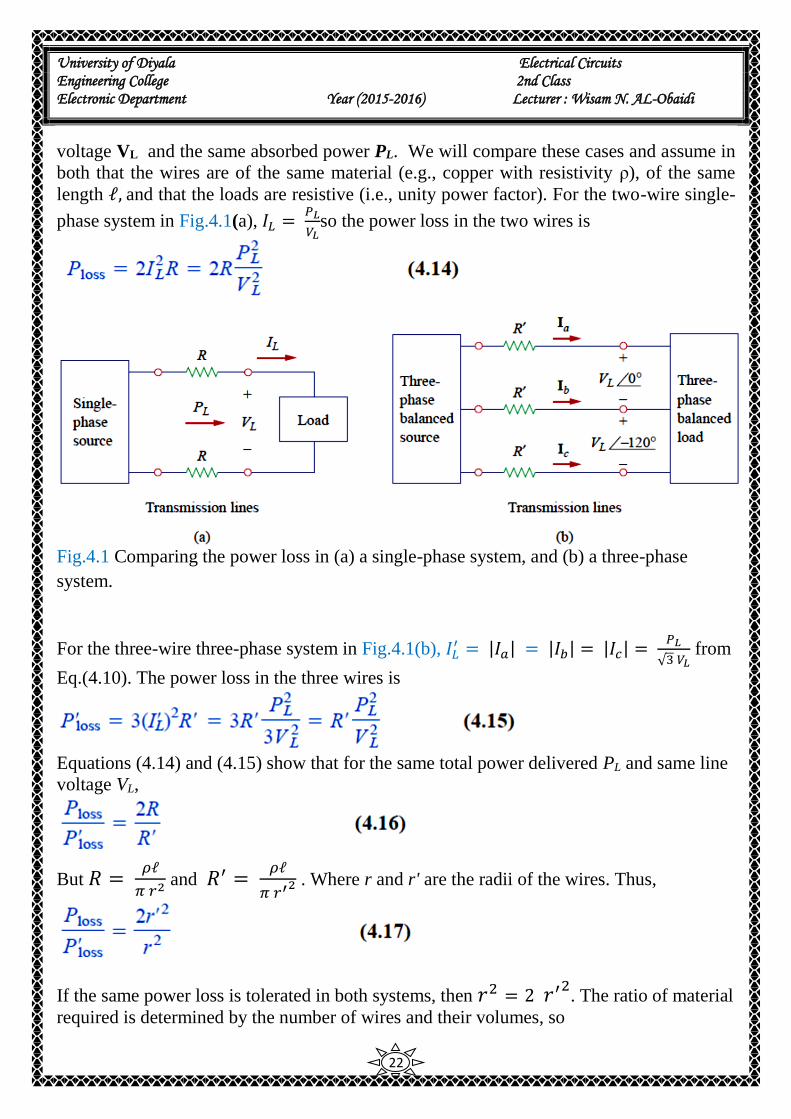
voltage VL and the same absorbed power PL. We will compare these cases and assume in
both that the wires are of the same material (e.g., copper with resistivity ρ), of the same
length ℓ, and that the loads are resistive (i.e., unity power factor). For the two-wire single-
phase system in Fig.4.1(a), 𝐼𝐿 = 𝑃𝐿
𝑉𝐿so the power loss in the two wires is
Fig.4.1 Comparing the power loss in (a) a single-phase system, and (b) a three-phase
system.
For the three-wire three-phase system in Fig.4.1(b), 𝐼𝐿′ = |𝐼𝑎| = |𝐼𝑏| = |𝐼𝑐| =
𝑃𝐿
√3 𝑉𝐿 from
Eq.(4.10). The power loss in the three wires is
Equations (4.14) and (4.15) show that for the same total power delivered PL and same line
voltage VL,
But 𝑅 = 𝜌ℓ
𝜋 𝑟2 and 𝑅′ =
𝜌ℓ
𝜋 𝑟′2 . Where r and r' are the radii of the wires. Thus,
If the same power loss is tolerated in both systems, then 𝑟2 = 2 𝑟′2
. The ratio of material
required is determined by the number of wires and their volumes, so
University of Diyala Electrical Circuits Engineering College 2nd Class Electronic Department Year (2015-2016) Lecturer : Wisam N. AL-Obaidi
23
since 𝑟2 = 2 𝑟′2
. Equation (4.18) shows that the single-phase system uses 33 percent
more material than the three-phase system or that the threephase system uses only 75
percent of the material used in the equivalent single-phase system. In other words,
considerably less mate-rial is needed to deliver the same power with a three-phase system
than is .required for a single-phase system
Example 6: For Example2. Determine the total average power, reactive power, and
complex power at the source and at the load.
Solution:
University of Diyala Electrical Circuits Engineering College 2nd Class Electronic Department Year (2015-2016) Lecturer : Wisam N. AL-Obaidi
24
H.W.6: For the Y-Y circuit in H.W.2, calculate the complex power at the source and at
the load.
Answer:
Example 7: A three-phase motor can be regarded as a balanced Y-load. A threephase
motor draws 5.6 kW when the line voltage is 220 V and the line current is 18.2 A.
Determine the power factor of the motor.
Solution:
H.W.7: Calculate the line current required for a 30-kW three-phase motor having a power
factor of 0.85 lagging if it is connected to a balanced source with a line voltage of 440 V.
Answer:
46.31 A.
University of Diyala Electrical Circuits Engineering College 2nd Class Electronic Department Year (2015-2016) Lecturer : Wisam N. AL-Obaidi
25
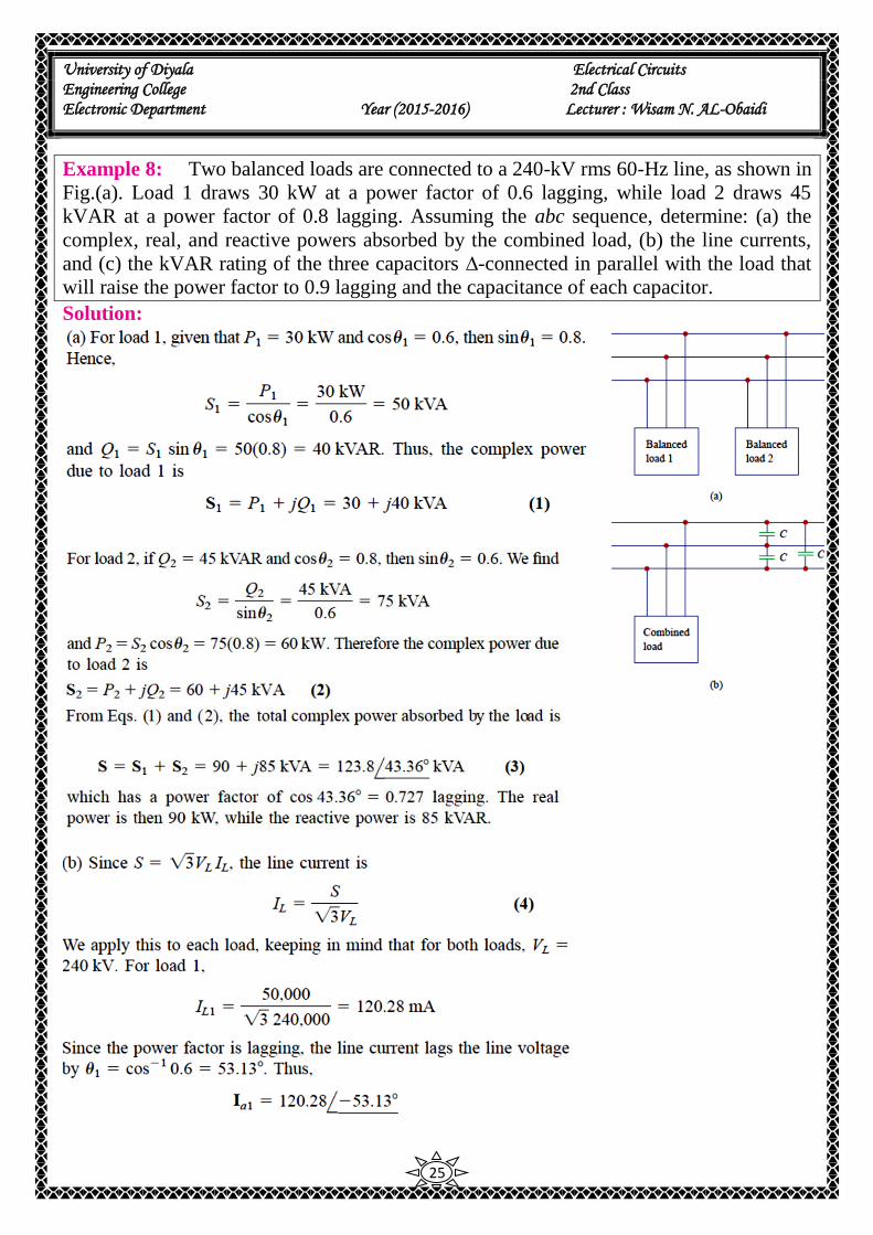
Example 8: Two balanced loads are connected to a 240-kV rms 60-Hz line, as shown in
Fig.(a). Load 1 draws 30 kW at a power factor of 0.6 lagging, while load 2 draws 45
kVAR at a power factor of 0.8 lagging. Assuming the abc sequence, determine: (a) the
complex, real, and reactive powers absorbed by the combined load, (b) the line currents,
and (c) the kVAR rating of the three capacitors ∆-connected in parallel with the load that
will raise the power factor to 0.9 lagging and the capacitance of each capacitor.
Solution:
University of Diyala Electrical Circuits Engineering College 2nd Class Electronic Department Year (2015-2016) Lecturer : Wisam N. AL-Obaidi
26

University of Diyala Electrical Circuits Engineering College 2nd Class Electronic Department Year (2015-2016) Lecturer : Wisam N. AL-Obaidi
27
H.W.8: Assume that the two balanced loads in Fig.(a) for Example 8 are supplied by an
840-V rms 60-Hz line. Load 1 is Y-connected with (30 + j40) Ω per phase, while load 2 is
a balanced three-phase motor drawing 48 kW at a power factor of 0.8 lagging. Assuming
the abc sequence, calculate: (a) the complex power absorbed by the combined load, (b) the
Kvar rating of each of the three capacitors ∆-connected in parallel with the load to raise
the power factor to unity, and (c) the current drawn from the supply at unity power factor
condition.
Answer:
5) Unbalanced Three-Phase Systems An unbalanced system is caused by two possible situations:
(1) the source voltages are not equal in magnitude and/or differ in phase by angles that are
unequal.
(2) load impedances are unequal.
An unbalanced system is due to unbalanced voltage sources or an unbalanced load.
To simplify analysis, we will assume balanced
source voltages, but an unbalanced load.
Unbalanced three-phase systems are solved by
direct application of mesh and nodal analysis.
Fig.5.1 shows an example of an unbalanced three-
phase system that consists of balanced source
voltages (not shown in the figure) and an
unbalanced Y-connected load (shown in the figure).
Since the load is unbalanced, ZA, ZB and ZC are not
equal. The line currents are determined by Ohm’s
law as
This set of unbalanced line currents produces current in the neutral line, which is not zero
as in a balanced system. Applying KCL at node N gives the neutral line current as
Fig.5.1 Unbalanced three-
phase Y -connected load.
University of Diyala Electrical Circuits Engineering College 2nd Class Electronic Department Year (2015-2016) Lecturer : Wisam N. AL-Obaidi
28
In a three-wire system where the neutral line is absent, we can still find the line currents Ia,
Ib and Ic using mesh analysis. At node N, KCL must be satisfied so that Ia+ Ib + Ic = 0 in
this case. The same could be done for an unbalanced ∆ -Y, Y-∆ or ∆-∆ three-wire system.
As mentioned earlier, in long distance power transmission, conductors in multiples of
three (multiple three-wire systems) are used, with the earth itself acting as the neutral
conductor.
To calculate power in an unbalanced three-phase system requires that we find the power in
each phase using Eqs. (4.6) to (4.9). The total power is not simply three times the power in
one phase but the sum of the powers in the three phases.
Example 9: The unbalanced Y-load of Fig.5.1 has balanced voltages of 100 V and the acb
sequence. Calculate the line currents and the neutral current. Take , ZA =15 Ω, ZB = 10 +
j5 Ω , ZC = 6 - j8 Ω
Solution:
Using Eq.(5.1), the line currents are
Using Eq.(5.2), the current in the neutral line is
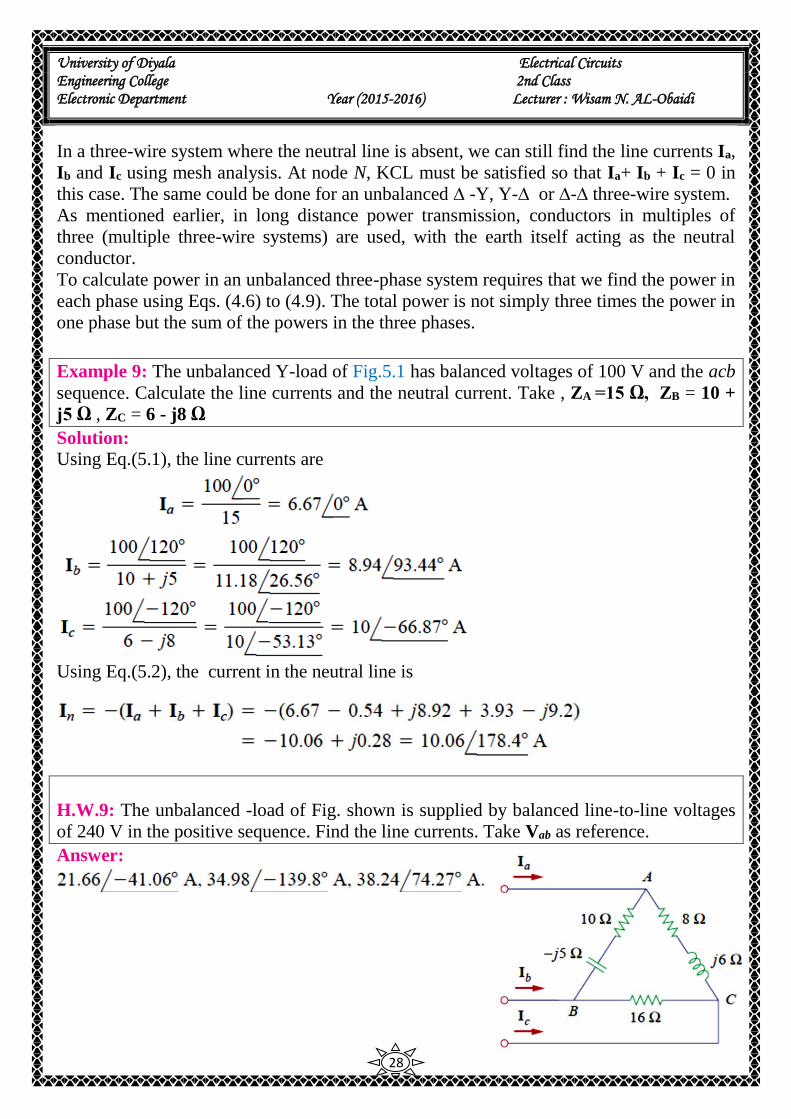
H.W.9: The unbalanced -load of Fig. shown is supplied by balanced line-to-line voltages
of 240 V in the positive sequence. Find the line currents. Take Vab as reference.
Answer:

University of Diyala Electrical Circuits Engineering College 2nd Class Electronic Department Year (2015-2016) Lecturer : Wisam N. AL-Obaidi
29
Example 10: For the unbalanced circuit in Fig. shown, find: (a) the line currents, (b) the
total complex power absorbed by the load, and (c) the total complex power absorbed by
the source.
Solution:
(a) We use mesh analysis to find the
required currents.
For mesh 1,
or
For mesh 2,
Equations (1) and (2) form a matrix equation:

University of Diyala Electrical Circuits Engineering College 2nd Class Electronic Department Year (2015-2016) Lecturer : Wisam N. AL-Obaidi
30
H.W.10: Find the line currents in the unbalanced three-phase circuit of Fig. shown and the
real power absorbed by the load.
Answer:
University of Diyala Electrical Circuits Engineering College 2nd Class Electronic Department Year (2015-2016) Lecturer : Wisam N. AL-Obaidi
31
6) Three-Phase Power Measurement A single wattmeter can measure the average power in a three-phase system that is
balanced, so that P1 = P2 = P3; the total power is three times the reading of that one
wattmeter. However, two or three single-phase wattmeter are necessary to measure power
if the system is unbalanced. However, there are two methods for measuring the power in
unbalanced three-phase systems;
1) Three-wattmeter method.
2) Two-wattmeter method.
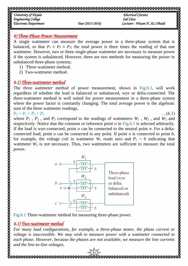
6.1) Three-wattmeter method The three wattmeter method of power measurement, shown in Fig.6.1, will work
regardless of whether the load is balanced or unbalanced, wye or delta-connected. The
three-wattmeter method is well suited for power measurement in a three-phase system
where the power factor is constantly changing. The total average power is the algebraic
sum of the three wattmeter readings,
PT = P1 + P2 + P3 …(6.1)
where P1 , P2 , and P3 correspond to the readings of wattmeters W1 , W2 , and W3 and
respectively. Notice that the common or reference point o in Fig.6.1 is selected arbitrarily.
If the load is wye-connected, point o can be connected to the neutral point n. For a delta-
connected load, point o can be connected to any point. If point o is connected to point b,
for example, the voltage coil in wattmeter W2 reads zero and P2 = 0 indicating that
wattmeter W2 is not necessary. Thus, two wattmeters are sufficient to measure the total
power.
Fig.6.1 Three-wattmeter method for measuring three-phase power.
6.1) Two-wattmeter method For many load configurations, for example, a three-phase motor, the phase current or
voltage is inaccessible. We may wish to measure power with a wattmeter connected to
each phase. However, because the phases are not available, we measure the line currents
and the line-to-line voltages.

University of Diyala Electrical Circuits Engineering College 2nd Class Electronic Department Year (2015-2016) Lecturer : Wisam N. AL-Obaidi
32
The two-wattmeter method is the most commonly used method for three-phase power
measurement. The two wattmeters must be properly connected to any two phases, as
shown typically in Fig.6.2. Notice that the current coil of each wattmeter measures the line
current, while the respective voltage coil is connected between the line and the third line
and measures the line voltage. Also notice that the ± terminal of the voltage coil is
connected to the line to which the corresponding current coil is connected. Although the
individual wattmeters no longer read the power taken by any particular phase, the
algebraic sum of the two wattmeter readings equals the total average power absorbed by
the load, regardless of whether it is wye- or delta-connected, balanced or unbalanced. The
total real power is equal to the algebraic sum of the two wattmeter readings,
PT = P1 + P2 …(6.2)
Fig.6.2 Two-wattmeter method for measuring three-phase power.
Now will show that the method works for a balanced three-phase system.
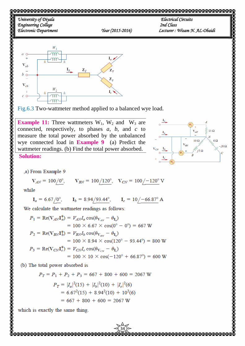
Consider the balanced, wye-connected load in Fig.6.3. Our objective is to apply the two-
wattmeter method to find the average power absorbed by the load. Assume the source is in
the abc sequence and the load impedance 𝑍𝑌 = 𝑍𝑌 ∠𝜃. Due to the load impedance, each
voltage coil leads its current coil by 𝜃, so that the power factor is 𝐶𝑂𝑆𝜃. We recall that
each line voltage leads the corresponding phase voltage by 300. Thus, the total phase
difference between the phase current and line voltage Vab is 𝜃 + 300, and the average
power read by wattmeter W1 and W2 are,
For the abc phase sequence for a balanced load,

University of Diyala Electrical Circuits Engineering College 2nd Class Electronic Department Year (2015-2016) Lecturer : Wisam N. AL-Obaidi
33
Similarly,
Note that the difference of the wattmeter readings is proportional to the total reactive
power, or
…(6.10)
Divide Equ.(6.6) on (6.8),
from which we can obtain the power factor as Thus, the two-wattmeter method not only
provides the total real and reactive powers, it can also be used to compute the power
factor. From Eqs. (6.7), (6.9), and (6.11), we conclude that:
Although these results are derived from a balanced wye-connected load, they are equally
valid for a balanced delta-connected load. However, the two-wattmeter method cannot be
used for power measurement in a three-phase four-wire system unless the current through
the neutral line is zero. We use the three-wattmeter method to measure the real power in a
three-phase four-wire system.
University of Diyala Electrical Circuits Engineering College 2nd Class Electronic Department Year (2015-2016) Lecturer : Wisam N. AL-Obaidi
34
Fig.6.3 Two-wattmeter method applied to a balanced wye load.
Example 11: Three wattmeters W1, W2 and W3 are
connected, respectively, to phases a, b, and c to
measure the total power absorbed by the unbalanced
wye connected load in Example 9 (a) Predict the
wattmeter readings. (b) Find the total power absorbed.
Solution:
University of Diyala Electrical Circuits Engineering College 2nd Class Electronic Department Year (2015-2016) Lecturer : Wisam N. AL-Obaidi
35
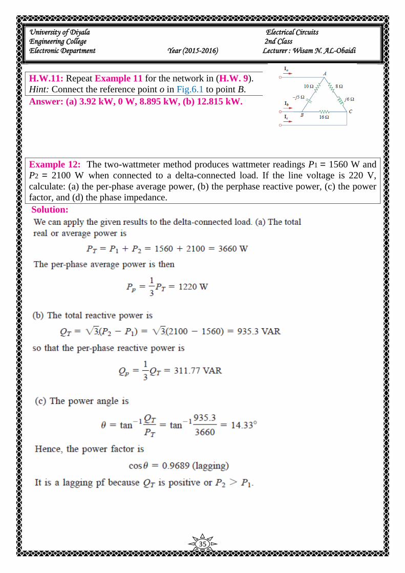
H.W.11: Repeat Example 11 for the network in (H.W. 9).
Hint: Connect the reference point o in Fig.6.1 to point B.
Answer: (a) 3.92 kW, 0 W, 8.895 kW, (b) 12.815 kW.
Example 12: The two-wattmeter method produces wattmeter readings P1 = 1560 W and
P2 = 2100 W when connected to a delta-connected load. If the line voltage is 220 V,
calculate: (a) the per-phase average power, (b) the perphase reactive power, (c) the power
factor, and (d) the phase impedance.
Solution:
University of Diyala Electrical Circuits Engineering College 2nd Class Electronic Department Year (2015-2016) Lecturer : Wisam N. AL-Obaidi
36
H.W.12: Let the line voltage VL = 208 V and the wattmeter readings of the balanced
system in Fig.6.2 be P1 = -560 W and P2 = 800 W. Determine:
(a) the total average power
(b) the total reactive power
(c) the power factor
(d) the phase impedance
Is the impedance inductive or capacitive?
Answer: (a) 240 W, (b) 2355.6 VAR, (c) 0.1014, (d) 18.25∠84.180 Ω, inductive.
Example 13: The three-phase balanced load in Fig.6.2 has impedance per phase of ZY =
8 + j6 Ω. If the load is connected to 208-V lines, predict the readings of the wattmeters
W1 and W2. Find PT and QT.
Solution:
University of Diyala Electrical Circuits Engineering College 2nd Class Electronic Department Year (2015-2016) Lecturer : Wisam N. AL-Obaidi
37
H.W.13: If the load in Fig.6.2 is delta-connected with impedance per phase of Zp = 30 –
j40 Ω and VL = 440 V. predict the readings of the wattmeters W1 and W2. Calculate PT and
QT.
Answer: 6.166 Kw, 0.8021 Kw, 6.968 Kw, -9.291 kVAR.
University of Diyala Electrical Circuits Engineering College 2nd Class Electronic Department Year (2015-2016) Lecturer : Wisam N. AL-Obaidi
1
vLecture () Three Phase Circuits
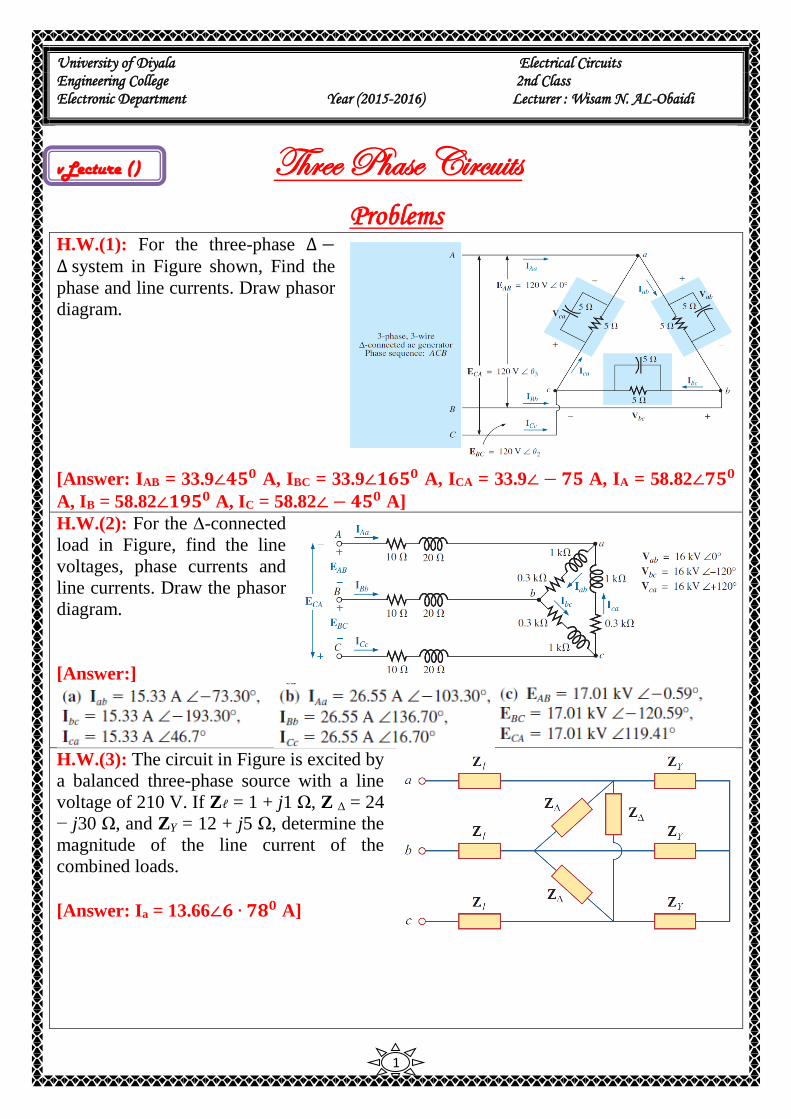
Problems H.W.(1): For the three-phase ∆ −∆ system in Figure shown, Find the
phase and line currents. Draw phasor
diagram.
[Answer: IAB = 33.9∠𝟒𝟓𝟎 A, IBC = 33.9∠𝟏𝟔𝟓𝟎 A, ICA = 33.9∠ − 𝟕𝟓 A, IA = 58.82∠𝟕𝟓𝟎
A, IB = 58.82∠𝟏𝟗𝟓𝟎 A, IC = 58.82∠ − 𝟒𝟓𝟎 A]
H.W.(2): For the ∆-connected
load in Figure, find the line
voltages, phase currents and
line currents. Draw the phasor
diagram.
[Answer:]
H.W.(3): The circuit in Figure is excited by
a balanced three-phase source with a line
voltage of 210 V. If Zℓ = 1 + j1 Ω, Z Δ = 24
− j30 Ω, and ZY = 12 + j5 Ω, determine the
magnitude of the line current of the
combined loads.
[Answer: Ia = 13.66∠𝟔 ∙ 𝟕𝟖𝟎 A]
University of Diyala Electrical Circuits Engineering College 2nd Class Electronic Department Year (2015-2016) Lecturer : Wisam N. AL-Obaidi
2
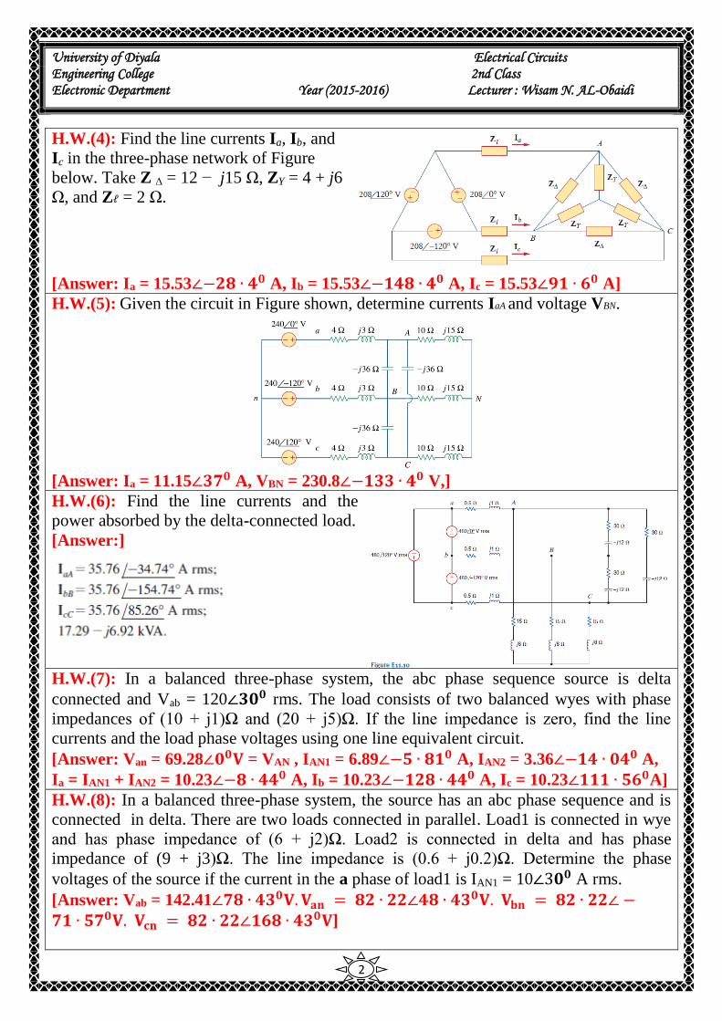
H.W.(4): Find the line currents Ia, Ib, and
Ic in the three-phase network of Figure
below. Take Z Δ = 12 − j15 Ω, ZY = 4 + j6
Ω, and Zℓ = 2 Ω.
[Answer: Ia = 15.53∠−𝟐𝟖 ∙ 𝟒𝟎 A, Ib = 15.53∠−𝟏𝟒𝟖 ∙ 𝟒𝟎 A, Ic = 15.53∠𝟗𝟏 ∙ 𝟔𝟎 A]
H.W.(5): Given the circuit in Figure shown, determine currents IaA and voltage VBN.
[Answer: Ia = 11.15∠𝟑𝟕𝟎 A, VBN = 230.8∠−𝟏𝟑𝟑 ∙ 𝟒𝟎 V,]
H.W.(6): Find the line currents and the
power absorbed by the delta-connected load.
[Answer:]
H.W.(7): In a balanced three-phase system, the abc phase sequence source is delta
connected and Vab = 120∠𝟑𝟎𝟎 rms. The load consists of two balanced wyes with phase
impedances of (10 + j1)Ω and (20 + j5)Ω. If the line impedance is zero, find the line
currents and the load phase voltages using one line equivalent circuit.
[Answer: Van = 69.28∠𝟎𝟎𝐕 = VAN , IAN1 = 6.89∠−𝟓 ∙ 𝟖𝟏𝟎 A, IAN2 = 3.36∠−𝟏𝟒 ∙ 𝟎𝟒𝟎 A,
Ia = IAN1 + IAN2 = 10.23∠−𝟖 ∙ 𝟒𝟒𝟎 A, Ib = 10.23∠−𝟏𝟐𝟖 ∙ 𝟒𝟒𝟎 A, Ic = 10.23∠𝟏𝟏𝟏 ∙ 𝟓𝟔𝟎A]
H.W.(8): In a balanced three-phase system, the source has an abc phase sequence and is
connected in delta. There are two loads connected in parallel. Load1 is connected in wye
and has phase impedance of (6 + j2)Ω. Load2 is connected in delta and has phase
impedance of (9 + j3)Ω. The line impedance is (0.6 + j0.2)Ω. Determine the phase
voltages of the source if the current in the a phase of load1 is IAN1 = 10∠3𝟎𝟎 A rms.
[Answer: Vab = 142.41∠𝟕𝟖 ∙ 𝟒𝟑𝟎𝐕. 𝐕𝐚𝐧 = 𝟖𝟐 ∙ 𝟐𝟐∠𝟒𝟖 ∙ 𝟒𝟑𝟎𝐕. 𝐕𝐛𝐧 = 𝟖𝟐 ∙ 𝟐𝟐∠ −𝟕𝟏 ∙ 𝟓𝟕𝟎𝐕. 𝐕𝐜𝐧 = 𝟖𝟐 ∙ 𝟐𝟐∠𝟏𝟔𝟖 ∙ 𝟒𝟑𝟎𝐕]
University of Diyala Electrical Circuits Engineering College 2nd Class Electronic Department Year (2015-2016) Lecturer : Wisam N. AL-Obaidi
3
H.W.(9): In a balanced three-phase wye–wye system, the source is an abc-sequence set of
voltages. The load voltage on the a phase is VAN = 120∠6𝟎𝟎 V rms, Zline = (2 + j1.4)Ω,
and Zload = (10 + j10)Ω. Determine the input voltages.
[Answer: Van = 140.4∠𝟓𝟖 ∙ 𝟓𝟎 V, Vbn = 140.4∠−𝟔𝟏 ∙ 𝟓𝟎 V, Vcn= 140.4∠𝟏𝟕𝟖 ∙ 𝟓𝟎 V]
H.W.(10): In a balanced three-phase wye–wye system, the load impedance is (8 + j4)Ω.
The source has phase sequence abc and Van = 120∠𝟎𝟎 V rms .If the load voltage is VAN =
111.62∠ − 1 ∙ 33𝟎 V rms determine the line impedance.
[Answer: Zline = (0.5 + j0.5)Ω]
H.W.(11): In a balanced three-phase wye–wye system, the total power loss in the lines is
400 W. VAN = 105.28∠𝟑𝟏 ∙ 𝟓𝟔𝟎 V rms and the power factor of the load is 0.77 lagging. If
the line impedance is 2 + j1 Ω, determine the load impedance.
[Answer: Zload = (5.74 + j4.75)Ω]
H.W.(12): In a balanced 3-phase Y–Y system, Zload = 20 + j12 Ω. The source has an abc-
phase sequence and Van = 120∠𝟎𝟎 V rms. If the load voltage is VAN = 111.49∠−𝟎 ∙ 𝟐𝟎 V
rms, determine the magnitude of the line current if the load is suddenly short-circuited.
[Answer: Ia = 67.4𝟐∠−𝟑𝟑 ∙ 𝟖𝟐𝟎 A rms]
H.W.(13): In a balanced three-phase delta–delta system, the source has an abc-phase
sequence. The phase angle for the source voltage is ∠𝐕𝒂𝒃 = 4𝟎𝟎 and Iab = 4∠15𝟎 A rms. If
the total power absorbed by the load is 1400 W, find the load impedance.
[Answer:𝒁𝒍𝒐𝒂𝒅∆ = 𝟑𝟐 ∙ 𝟏𝟔∠𝟐𝟓𝟎𝛀]
H.W.(14): In a balanced three-phase system, the source has an abc-phase sequence and is
connected in delta. There are two parallel wye-connected loads. The phase impedance
of load 1 and load 2 is 4 + j4Ω and 10 + j4 Ω respectively. The line impedance connecting
the source to the loads is 0.3 + j0.2 Ω. If the current in the a phase of load 1 is IAN1 =
10∠20𝟎 A find the delta currents in the source.
[Answer: Iab = 8.64∠𝟓𝟕 ∙ 𝟗𝟒𝟎 A, Ibc = 8.64∠−𝟔𝟐 ∙ 𝟏𝟎 A, Ica = 8.64∠𝟏𝟕𝟕 ∙ 𝟗𝟒𝟎 A]
H.W.(15): The magnitude of the complex power (apparent power) supplied by a three-
phase balanced Y–Y system is 3600 VA. The line voltage is 208 V rms. If the line
impedance is negligible and the power factor angle of the load is 250 determine Zload.
[Answer:Zload = 12∠𝟐𝟓𝟎 Ω]
H.W.(16): A three-phase abc-sequence wye-connected source supplies 14 kVA with a
power factor of 0.75 lagging to a delta load. If the delta load consumes 12 kVA at a power
factor of 0.7 lagging and has a phase current of 10∠𝟑𝟎𝟎, determine the per-phase
impedance of the load and the line.
[Answer: Zload∆ = 40∠𝟒𝟓 ∙ 𝟓𝟕𝟎 Ω, Zline = 2.43 + j0.776 Ω]
H.W.(17): A balanced three-phase source serves the following loads:
Load 1: 20 kVA at 0.8 pf lagging
Load 2: 10 kVA at 0.7 pf leading
Load 3: 10 kW at unity pf
Load 4: 16 kVA at 0.6 pf lagging
The line voltage at the load is 208 V rms at 60 Hz, and the line impedance is 0.02 + j0.04

University of Diyala Electrical Circuits Engineering College 2nd Class Electronic Department Year (2015-2016) Lecturer : Wisam N. AL-Obaidi
4
Ω. Find the line current, voltage and power factor at the source.
[Answer: : Ia = 128.1∠−𝟐𝟐 ∙ 𝟓𝟑𝟎 A ,Van = 249.83∠−𝟑𝟖 ∙ 𝟑𝟖𝟎 A, pf = 0.912 lagging]
H.W.(18): A balanced three-phase source supplies power to three loads. The loads are
Load 1: 24 kVA at 0.6 pf lagging
Load 2: 10 kW at 0.75 pf lagging
Load 3: unknown
If the line voltage at the load is 208 V rms, the magnitude of the total complex power is
35.52 kVA, and the combined power factor at the load is 0.88 lagging, find the unknown
load.
[Answer: S3 = 13.09∠−𝟓𝟖 ∙ 𝟑𝟗𝟎 kVA]
H.W.(19): Determine the complex power delivered to the three-phase load of a four-wire
Y- Y circuit. The phase voltages of the Y-connected source are Van = 110∠00 V rms, Vbn =
110∠-1200 V rms, and Vcn = 110∠1200 V rms. The load impedances are ZA = 50 + j80 Ω;
ZB = j50 Ω, and ZC = 100 + j25 Ω.
[Answer: SA = 68 + j109 VA, SB = j242 VA, SC = 114 + j128 VA, ST = 182 + j379 VA]
H.W.(20): Determine the complex power delivered to the 3-phase load of a four-wire Y-Y
circuit. The phase voltages of the Y-connected source are Van = 110∠00 V, Vbn = 110∠-
1200 V, and Vcn = 110∠1200 V. The load impedances are ZA = ZB = ZC = 50 + j80 Ω.
[Answer: SA = SB = SC = 68 + j109 VA, ST = 204 + j327 VA]
H.W.(21): Determine the complex power delivered to the three-phase load of a three-wire
Y- Y circuit. The phase voltages of the Y-connected source are Van = 110∠00 V rms, Vbn =
110∠-1200 V rms, and Vcn = 110∠1200 V rms. The load impedances are ZA = 50 + j80 Ω;
ZB = j50 Ω, and ZC = 100 + j25 Ω.
[Answer: SA = 146 + j234 VA, SB = j94 VA, SC = 141 + j35 VA, ST = 287 + j364 VA]
H.W.(22): Determine the complex power delivered to the three-phase load of a three-wire
Y- Y circuit. The phase voltages of the Y-connected source are Van = 110∠00 V rms, Vbn =
110∠-1200 V rms, and Vcn = 110∠1200 V rms. The load impedances are ZA = ZB = ZC = 50
+ j80 Ω.
[Answer: SA = SB = SC = 68 + j109 VA, ST = 204 + j327 VA]
H.W.(23): For the ∆ −Y connected load in Figure
shown. Find the total active, reactive and apparent
power, also find the load power factor.
[Answer: PT∆ = 7200 W, Q T∆ = 9600 VAR (capacitve), S T∆ = 12000 VA, PTY =
6414.41 W, QTY = 4810.81 VAR (inductive), STY = 8045.76 VA, PT = 13614.41 W, Q T
= 4789.19 VAR, S T = 14432.2 VA, cos𝝋 = 0.943 leading]
University of Diyala Electrical Circuits Engineering College 2nd Class Electronic Department Year (2015-2016) Lecturer : Wisam N. AL-Obaidi
5
H.W.(24): Three identical impedances of 12∠𝟑𝟎𝟎
ohms in a ∆-connection and three identical
impedances of 15∠𝟒𝟓𝟎 ohms in Y-connection are
both on the same three-phase, three-wire 208 V
system ABC system. Find the line currents and total
active power.
[Answer: IL = 53.6∠−𝟑𝟔. 𝟔𝟎A, P = 15500 W]
H.W.(25): A three-phase source delivers 4800 VA to a wye-connected load with a phase
voltage of 208 V and a power factor of 0.9 lagging. Calculate the source line current and
the source line voltage.
[Answer: IL = 7.69 A, VL = 360.3 V]
H.W.(26): A balanced wye-connected load with a phase impedance of 10 – j16 Ω is
connected to a balanced three-phase generator with a line voltage of 220 V. Determine the
line current and the complex power absorbed by the load.
[Answer: IL = 6.732 A, S = 2565∠−𝟓𝟖𝟎 VA]
H.W.(27): A 4200-V, three-phase transmission line has an impedance of 4 + j10 Ω per
phase. If it supplies a load of 1 MVA at 0.75 power factor (lagging), find:
(a) the complex power
(b) the power loss in the line
(c) the voltage at the sending end
[Answer: S = 0.75 + j0.6614 MVA, PL = 25.19 kW, V = 4.443∠−𝟐 ∙ 𝟕𝟎𝟗𝟎 V]
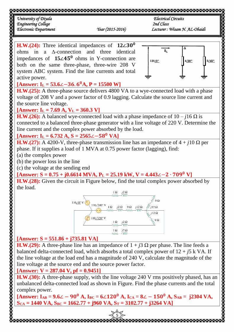
H.W.(28): Given the circuit in Figure below, find the total complex power absorbed by
the load.
[Answer: S = 551.86 + j735.81 VA]
H.W.(29): A three-phase line has an impedance of 1 + j3 Ω per phase. The line feeds a
balanced delta-connected load, which absorbs a total complex power of 12 + j5 k VA. If
the line voltage at the load end has a magnitude of 240 V, calculate the magnitude of the
line voltage at the source end and the source power factor.
[Answer: V = 287.04 V, pf = 0.9451]
H.W.(30): A three-phase supply, with the line voltage 240 V rms positively phased, has an
unbalanced delta-connected load as shown in Figure. Find the phase currents and the total
complex power.
[Answer: IAB = 9.6∠ − 𝟗𝟎𝟎 A, IBC = 6∠𝟏𝟐𝟎𝟎 A, ICA = 8∠ − 𝟏𝟓𝟎𝟎 A, SAB = j2304 VA,
SCA = 1440 VA, SBC = 1662.77 + j960 VA, ST = 3102.77 + j3264 VA]
University of Diyala Electrical Circuits Engineering College 2nd Class Electronic Department Year (2015-2016) Lecturer : Wisam N. AL-Obaidi
6
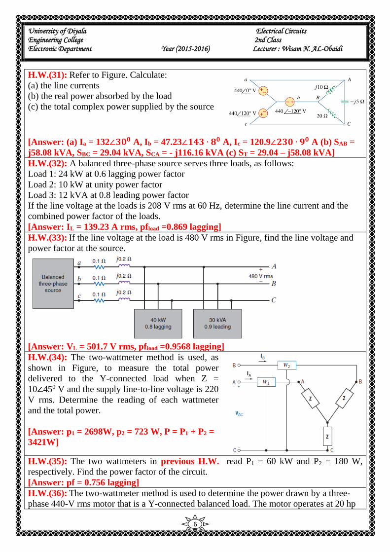
H.W.(31): Refer to Figure. Calculate:
(a) the line currents
(b) the real power absorbed by the load
(c) the total complex power supplied by the source
[Answer: (a) Ia = 132∠𝟑𝟎𝟎 A, Ib = 47.23∠𝟏𝟒𝟑 ∙ 𝟖𝟎 A, Ic = 120.9∠𝟐𝟑𝟎 ∙ 𝟗𝟎 A (b) SAB =
j58.08 kVA, SBC = 29.04 kVA, SCA = - j116.16 kVA (c) ST = 29.04 – j58.08 kVA]
H.W.(32): A balanced three-phase source serves three loads, as follows:
Load 1: 24 kW at 0.6 lagging power factor
Load 2: 10 kW at unity power factor
Load 3: 12 kVA at 0.8 leading power factor
If the line voltage at the loads is 208 V rms at 60 Hz, determine the line current and the
combined power factor of the loads.
[Answer: IL = 139.23 A rms, pfload =0.869 lagging]
H.W.(33): If the line voltage at the load is 480 V rms in Figure, find the line voltage and
power factor at the source.
[Answer: VL = 501.7 V rms, pfload =0.9568 lagging]
H.W.(34): The two-wattmeter method is used, as
shown in Figure, to measure the total power
delivered to the Y-connected load when Z =
10∠450 V and the supply line-to-line voltage is 220
V rms. Determine the reading of each wattmeter
and the total power.
[Answer: p1 = 2698W, p2 = 723 W, P = P1 + P2 =
3421W]
H.W.(35): The two wattmeters in previous H.W. read P1 = 60 kW and P2 = 180 W,
respectively. Find the power factor of the circuit.
[Answer: pf = 0.756 lagging]
H.W.(36): The two-wattmeter method is used to determine the power drawn by a three-
phase 440-V rms motor that is a Y-connected balanced load. The motor operates at 20 hp
University of Diyala Electrical Circuits Engineering College 2nd Class Electronic Department Year (2015-2016) Lecturer : Wisam N. AL-Obaidi
7
at 74.6
percent efficiency. The magnitude of the line current is 52.5 A rms. The wattmeters are
connected in the A and C lines. Find the reading of each wattmeter. The motor has a
lagging power factor.
[Answer: ]
H.W.(37): A three-phase system has a line-to-line voltage of 4000 V rms and a balanced
∆ -connected load with Z = 40 + j30 V. The phase sequence is abc. Use the two wattmeters
connected to lines A and C, with line B as the common line for the voltage measurement.
Determine the total power measurement recorded by the wattmeters.
[Answer: P = 768 kW]
H.W.(38): A three-phase system with a sequence abc and a line-to-line voltage of 200 V
rms feeds a Y-connected load with Z = 70.7∠450 V. Find the line currents. Find the total
power by using two wattmeters connected to lines B and C.
[Answer: P = 400W]
H.W.(39): A three-phase system with a line-to-line voltage of 208 V rms and phase
sequence abc is connected to a Y-balanced load with impedance 10∠ −300 Ω and a
balanced ∆ load with impedance 15∠300 Ω. Find the line currents and the total power
using two wattmeters.
[Answer: ]
H.W.(40): The two-wattmeter method is used. The wattmeter in line A reads 920 W, and
the wattmeter in line C reads 460 W. Find the impedance of the balanced ∆-connected
load. The circuit is a three-phase 120-V rms system with an abc sequence.
[Answer: Z∆ = 27.1∠300_ Ω]
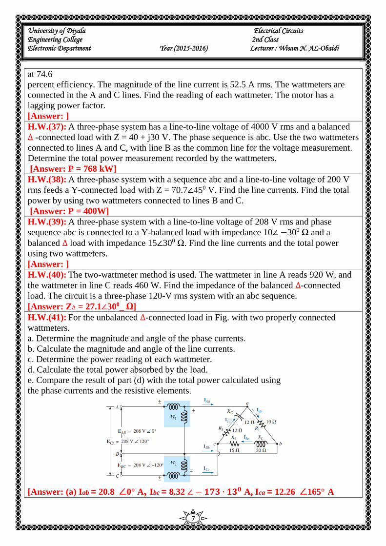
H.W.(41): For the unbalanced ∆-connected load in Fig. with two properly connected
wattmeters.
a. Determine the magnitude and angle of the phase currents.
b. Calculate the magnitude and angle of the line currents.
c. Determine the power reading of each wattmeter.
d. Calculate the total power absorbed by the load.
e. Compare the result of part (d) with the total power calculated using
the phase currents and the resistive elements.
[Answer: (a) Iab = 20.8 ∠0° A, Ibc = 8.32 ∠ − 𝟏𝟕𝟑 ∙ 𝟏𝟑𝟎 A, Ica = 12.26 ∠165° A
University of Diyala Electrical Circuits Engineering College 2nd Class Electronic Department Year (2015-2016) Lecturer : Wisam N. AL-Obaidi
8
(b) Ia = 32.79 ∠-5.55° A, Ib = 29.08 ∠ − 𝟏𝟕𝟖 ∙ 𝟎𝟑𝟎 A, Ic = 5.5 ∠130.65° A
(c)P1 = 6788.35 W, P2 = 379.1 W (d) PT = 7167.45 W (e) PT = 7168.43 W (The slight
difference is due to the level of accuracy carried through the calculations.)]
H.W.(42): The two-wattmeter method gives P1 = 1200 W and P2 = –400 W for a three-
phase motor running on a 240-V line. Assume that the motor load is wye-connected and
that it draws a line current of 6 A. Calculate the pf of the motor and its phase impedance.
[Answer: pf = 0.4472 (leading), Zp = 40∠ − 𝟔𝟑 ∙ 𝟒𝟑𝟎Ω ]
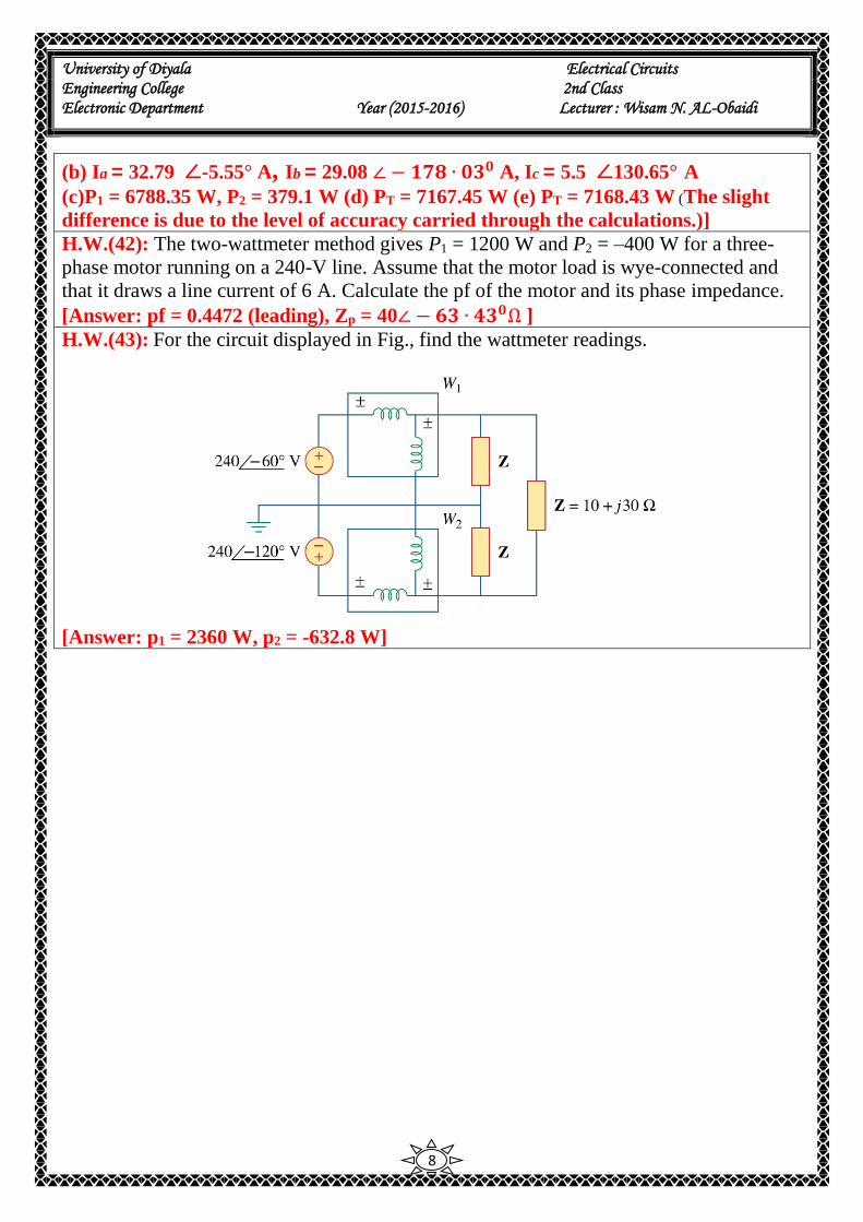
H.W.(43): For the circuit displayed in Fig., find the wattmeter readings.
[Answer: p1 = 2360 W, p2 = -632.8 W]