Embed Size (px)
Citation preview

An LED-to-LED Visible Light Communication System with Software-Based Synchronization
Stefan Schmid1,2, Giorgio Corbellini2, Stefan Mangold2, Thomas R. Gross1
1ETH Zurich, 2Disney Research Zurich
Motivation – Networking Toys
• Requirements:
• Low bit rate communication
• Short distances
• Cost-effective
• LED-to-LED communication:
• Fulfills requirements
• Communication is visible
• No radio waves
• Reuses already existing components
• Low-complexity
2
Outline
• Motivation
• Technology
• LED as a Transmitter
• LED as a Receiver
• Synchronization
• Implementation and Platform
• Evaluation
• Conclusions
3
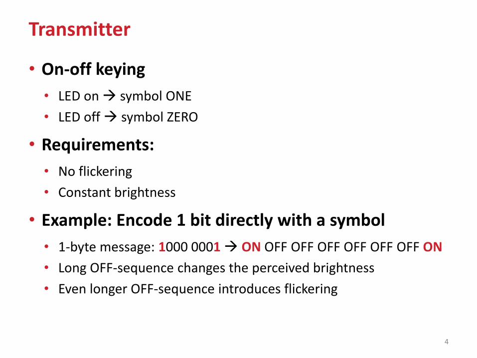
Transmitter
• On-off keying
• LED on symbol ONE
• LED off symbol ZERO
• Requirements:
• No flickering
• Constant brightness
• Example: Encode 1 bit directly with a symbol
• 1-byte message: 1000 0001 ON OFF OFF OFF OFF OFF OFF ON
• Long OFF-sequence changes the perceived brightness
• Even longer OFF-sequence introduces flickering
4
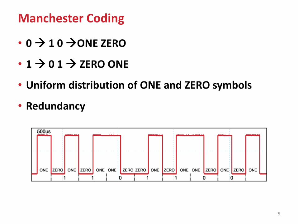
Manchester Coding
• 0 1 0 ONE ZERO
• 1 0 1 ZERO ONE
• Uniform distribution of ONE and ZERO symbols
• Redundancy
5
LEDs as Light Receivers
• LEDs can be used as light receivers [Dietz et al, 2003]
• LED used as a receiver:
• Reduces complexity
• Cost-effective
• Limited light sensitivity
But
• Short range communication
• Low data rates
still possible
6
P. Dietz, W. Yerazunis, and D. Leigh, “Very low-cost sensing and communication using bidirectional LEDs,” in UbiComp 2003: Ubiquitous Computing. Springer, 2003, pp. 175–191.
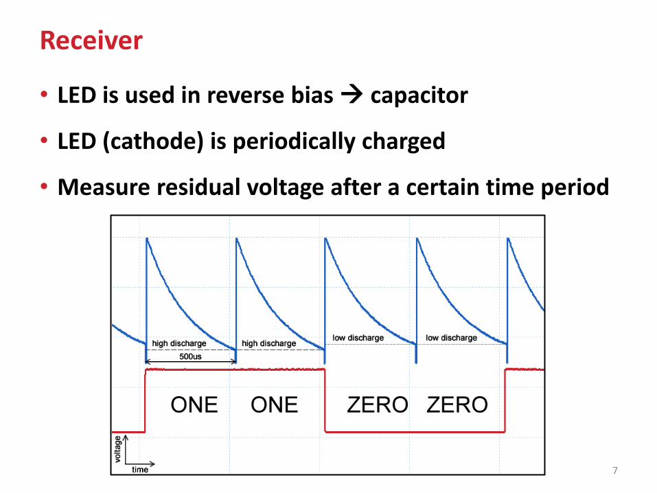
Receiver
7
• LED is used in reverse bias capacitor
• LED (cathode) is periodically charged
• Measure residual voltage after a certain time period
Threshold
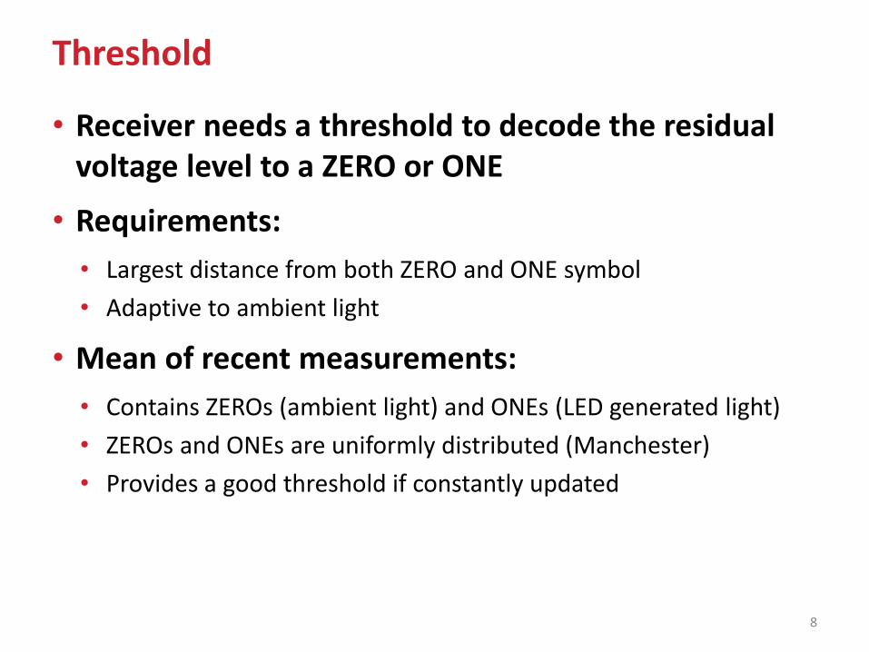
• Receiver needs a threshold to decode the residual voltage level to a ZERO or ONE
• Requirements:
• Largest distance from both ZERO and ONE symbol
• Adaptive to ambient light
• Mean of recent measurements:
• Contains ZEROs (ambient light) and ONEs (LED generated light)
• ZEROs and ONEs are uniformly distributed (Manchester)
• Provides a good threshold if constantly updated
8
Synchronization (1)
9
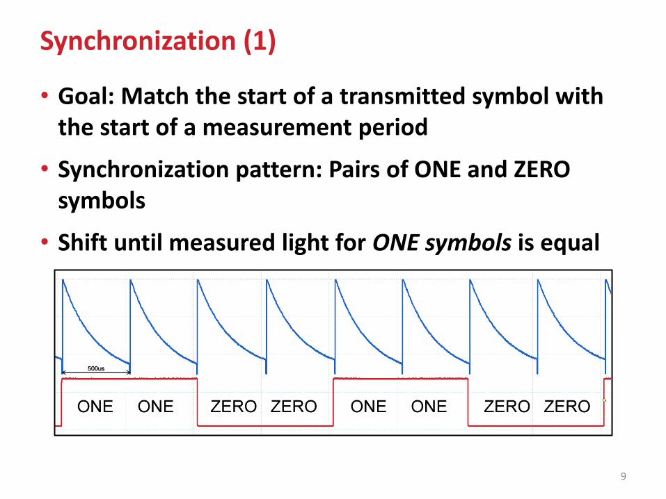
• Goal: Match the start of a transmitted symbol with the start of a measurement period
• Synchronization pattern: Pairs of ONE and ZERO symbols
• Shift until measured light for ONE symbols is equal
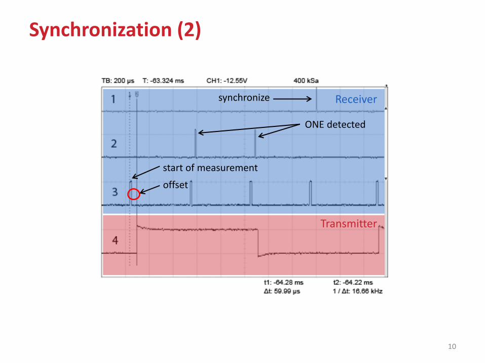
Synchronization (2)
10
Transmitter
Receiver
ONE detected
synchronize
start of measurement
offset
Always «on»
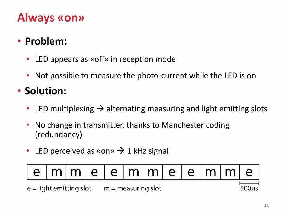
11
• Problem:
• LED appears as «off» in reception mode
• Not possible to measure the photo-current while the LED is on
• Solution:
• LED multiplexing alternating measuring and light emitting slots
• No change in transmitter, thanks to Manchester coding (redundancy)
• LED perceived as «on» 1 kHz signal
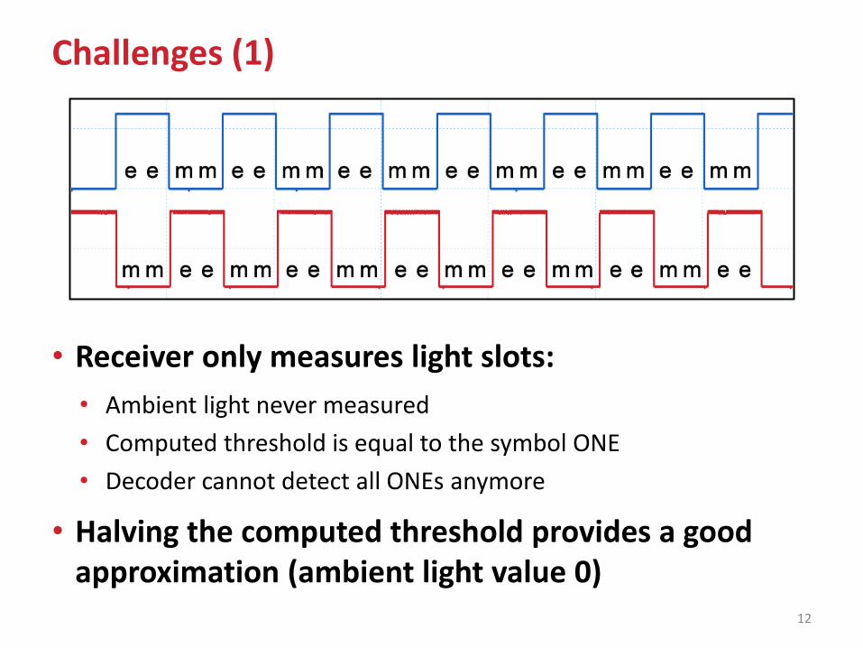
Challenges (1)
• Receiver only measures light slots:
• Ambient light never measured
• Computed threshold is equal to the symbol ONE
• Decoder cannot detect all ONEs anymore
• Halving the computed threshold provides a good approximation (ambient light value 0)
12
Challenges (2)
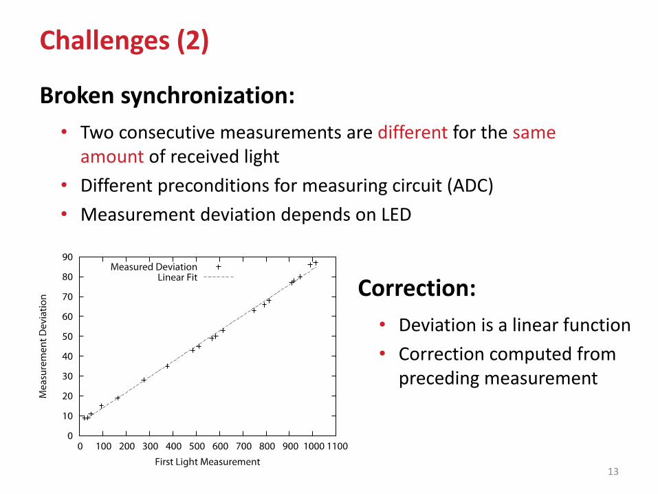
Broken synchronization:
• Two consecutive measurements are different for the same amount of received light
• Different preconditions for measuring circuit (ADC)
• Measurement deviation depends on LED
13
Correction:
• Deviation is a linear function
• Correction computed from preceding measurement
Outline
• Motivation
• Technology
• LED as a Transmitter
• LED as a Receiver
• Synchronization
• Implementation and Platform
• Evaluation
• Conclusions
14
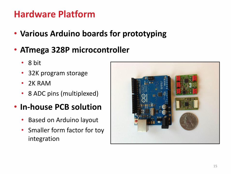
Hardware Platform
• Various Arduino boards for prototyping
• ATmega 328P microcontroller
• 8 bit
• 32K program storage
• 2K RAM
• 8 ADC pins (multiplexed)
• In-house PCB solution
• Based on Arduino layout
• Smaller form factor for toy integration
15
Implementation
• Flexible software implementation (C++, AVR-g++) of physical and MAC layer
• Hardware:
• ADC
• Timers
• Software:
• Synchronization
• Encoding / Decoding
• MAC
• MAC
• Acknowledgments/ Retransmissions
• CRC
16
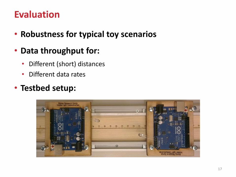
Evaluation
17
• Robustness for typical toy scenarios
• Data throughput for:
• Different (short) distances
• Different data rates
• Testbed setup:
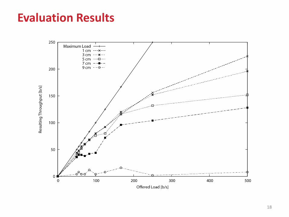
Evaluation Results
18
Conclusions
• Short-range communication system for toys
• VLC based on only LEDs
• Low-cost
• Low-complexity
• Software driven physical/MAC layer
• Short distance communication
• 100-200 b/s data rates
19

20
Thank you!