Embed Size (px)
Citation preview

RESEARCH XFT cAaxlQg QmQs MEMORANDUM
FLIGHT INVESTIGATION O F A LIQUID -HYDROGEN FUEL SYSTEM
By Donald R. Mulholland, Loren W. Acker, Harold H. Christenson, and William V. Gough
Lewis Flight Propulsion Laboratory Cleveland, Ohio
CLASSIFIED DOCUMENT - TITLE UNCLASSIF'ED
This material contains information affecting the national defense of the United States within the meaning of the espionage laws, Title 18, U.S.C., Secs. 793 and 794, the transmission o r revelation of which in any manner to an unauthorized person i s prohibited by law.
ONAL ADV SORY COMM FOR AERONAUT
WASHINGTON A~gust 19, 1957
Reclassified May 29, 1959

NACA RM E57F19a - CONFIDENTIAL
NATIONAL ADVISORY COMMITTEE FOR AERONAUTICS
FLIGHT INVElSTIGATION OF A LIQUID-HYDROGEN FUEL SYSTEM*
By Donald R. Mulholland, Loren W. Acker, Harold H. Christenson, and W i l l i a m V. Gough
SUMMARY
A twin-engine l i g h t bomber was modified t o u t i l i z e hydrogen f u e l i n one of the two engines during f l i g h t at an a l t i t u d e of 50,000 f e e t . The f u e l was s to red as a l i qu id i n an insulated wingtip tank. A pressurized f u e l system w a s used i n l i e u of a pump fo r l i qu id hydrogen. The f u e l system provided f o r vaporization of the f u e l i n a ram-air heat exchanger and regulat ion of hydrogen vapor flow t o the engine by means of a special ly designed regulator . The regulator u t i l i z e d the metered JP f u e l flow from the standard engine t h r o t t l e control t o regulate vaporized hydrogen flow t o t h e engine.
Three completely successful f l i g h t s were made using hydrogen fue l . The a i rplane climbed on 3P f u e l t o cruise a l t i t ude , where t he engine was sh i f t ed t o hydrogen f u e l and then back t o JP f u e l a f t e r the hydrogen supply was exhausted. Transit ion was made t o hydrogen f u e l without serious e f f ec t s on engine operation. Steady-state and t rans ien t operation were both highly sa t i s fac tory . Heat-exchanger performance compared favorably with simulated a l t i t u d e performance i n the laboratory. During operation with hydrogen, t he engine produced a very heavy and pers i s ten t condensa- t i o n t r a i l , while the engine using JP f u e l produced none.
Data a re presented t o show the e f f e c t of tank ag i ta t ion on f u e l pres- sure and f u e l losses . Jo s t l i ng of t he l i qu id during f l i g h t and especial ly during tax i ing subs tan t ia l ly reduced the r a t e of pressure increase i n t he tank.
Hydrogen gas created by f u e l boi loff was periodically vented from the tank during flight, and on two occasions unused l i qu id hydrogen was je t t i soned from the f u e l tank without incident . .
The des i re f o r improvement of United S ta tes mi l i t a ry a i r capabi l i ty t o operate a t higher a l t i t udes and to f l y f a r the r has led t o an
* Ti t l e , Unclassified.
CONFIDENTIAL

CONFIDENTIAL
inves t iga t ion of the use of hydrogen as an a i r c r a f t f u e l where the f u e l would be s to red as a l i qu id . During the p a s t 2 years a number of s tud ies have been made at the NACA Lewis laboratory r e l a t i v e t o t h i s use of hydro- gen, The r e s u l t s of ana ly t i c a l s tud ies indicate t ha t a very subs t an t i a l ga in may be obtained i n a l t i t u d e and range by the use of hydrogen i n tu rbo je t engines as opposed t o JP f u e l ( r e f . 1). Combustion performance of hydrogen over a wide range of pressure conditions has been highly s a t i s f a c t o r y even when it w a s introduced i n to the combustor a t tempera- t u r e s a s low a s 50' R ( r e f s , 2 and 3 ) .
Furthermore, s a t i s f ac to ry combustion has been a t t a ined i n very sho r t combustors, which would allow f o r t h e p o s s i b i l i t y of r e l a t i v e l y sho r t engines compared wi th present JP f u e l engines and would i n t u r n give commensurate savings i n engine weight and space requirements ( r e f s . 4 and 5) -
The p r a c t i c a l problems associa ted wi th t h e handling of l i q u i d hydro- gen, because of i t s low densi ty (4.42 lb/cu f t ) and low temperature (-423' F), a r e unique and requ i re s p e c i a l equipment design along w i t h spec i a l heat insu la t ion techniques f o r the s torage tank ( r e f . 6 ) and other pa s t s of t h e hydrogen handling system,
I n view of t he foregoing over -a l l advantages, a program w a s i n s t i ga t ed at the NACA Lewis laboratory i n January, 1956, t o const ruct an a i r c r a f t f u e l system fo r f l i g h t operation. By t h i s means the p r a c t i c a l problems, many of which can only be exposed by ac tua l f l i g h t , could be inves t i - gated. The system devised is not t o be considered an ult imate design, even though some p a r t s of the system would no doubt have d i r e c t applica- t i o n i n an ul t imate system. A pressur ized f u e l system w a s used, s ince a s a t i s f a c t o r y liquid-hydrogen pump w a s not avai lable f o r a i r c r a f t app l ica t ion .
The f u e l system w a s designed t o supply one tu rbo je t engine of a twin- engine l i g h t bomber. The supply was t o be su f f i c i en t t o operate t he engine f o r 20 t o 30 minutes at 98 percent of r a t ed speed at an a l t i t u d e of 50,000 f e e t and a f l i g h t Mach number of 0.72.
The durat ion of f l i g h t using hydrogen f u e l w a s t o be only long enough t o f i rmly e s t a b l i s h s a t i s f ac to ry fuel-system and engine operation. For t h i s reason, only one of t he two engines was modified f o r operation with hydrogen f u e l . The hydrogen was s t o r ed as a l i qu id i n t h e f u e l tank, and it was burned as a cold vapor. No e f f o r t s were made during t h i s program t o u t i l i z e t h e f u e l as a heat s ink .
Presented here in is a complete descr ip t ion of t h e f u e l system and its operation during f l i g h t . Discussion i s a l s o presented of f u e l s torage cha rac t e r i s t i c s , engine operation during t r a n s i t i o n t o hydrogen f u e l , and r e s u l t s of f u e l venting and j e t t i son ing during f l i g h t . The f l i g h t i n s t ru - mentation f o r t h e liquid-hydrogen f u e l system is described i n t h e appendix by Sco t t H. Simpkinson and Jacob C. Moser,
CONFIDENTIAL

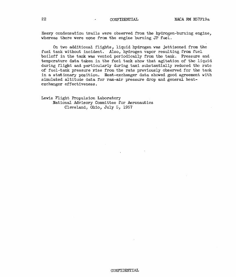
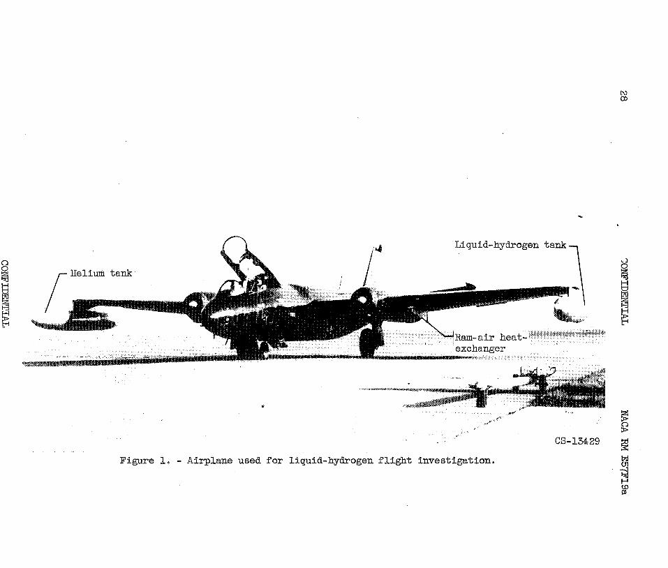
The a i r c r a f t used f o r the hydrogen f l i g h t program w a s a B-57 twin- engine bomber. A photograph of the airplane with the hydrogen system ins t a l l ed is shown i n f igure 1. This a i r c r a f t is capable of cruise at a 50,000-foot a l t i t ude and carr ies a crew of two i n forward and r ea r sea ts under a s ingle canopy. Only the forward sea t contained the p i l o t ' s con- t r o l s . The r ea r cockpit was modified t o accept a special control panel f o r the hydrogen system.
General Arrangement of Systems
The arrangement of the hydrogen system on the a i r c r a i s shown i n f igure 2. A schematic drawing t o i l l m t r a t e the functioning of the hydro- gen system and the associated equipment is given i n figure 3. The liquid- f u e l supply tank was mounted on the l e f t wingtip of the airplane ( f ig . 4 ) . A vacuum-jacketed l iquid-fuel l i n e from the hydrogen tank extended inboard jus t aft of the single main spar t o the bottom of a ram-air heat exchanger, which w a s mounted i n the ammunition bay just outboard of the engine na- ce l le . The liquid-hydrogen f u e l was vaporized i n the heat exchanger, and an unjacketed l i n e then carr ied the cold vapor from the top of the heat exchanger through t h e special hydrogen regulator, also mounted i n the ammunition-bay area, t o the hydrogen f u e l manifold surrounding the engine-
The fue l supply t o the engine was controlled by two shutoff valves shown i n the schematic diagram ( f ig . 3 ) . One was located i n the l iquid l ine near the tank (valve 5), and the second was located i n the vapor l i n e near the engine (valve 3) . A manually controlled f uel-tank vent valve (valve 10) was provided t o re l ieve the tank pressure when it reached a cer ta in maximum due to accumulation of f u e l boi loff . Emergency provisions were included i n the system to empty the l iquid hydrogen from the tank. These were a manually controlled d u w valve (valve 6) and a rupture disk i n the tank t o rel ieve tank pressure automatically i f other means of pres- sure r e l i e f f a i l ed . The helium supply necessary for purging and pres- surizing was carr ied i n a tank mounted on the r ight wingtip.
The JP f u e l system i n the airplane was a l te red t o u t i l i z e the metered JP f u e l flow t o control the flow of hydrogen t o the engine. This was accomplished by adding a JT f u e l bypass *om the exis t ing t h r o t t l e control through the hydrogen flow regulator and back t o the main JP fue l tank. Shutoff valves (valves 1 and 2) were ins t a l l ed i n the JT f u e l system t o d i rec t flow i n the bypass l i ne and i n the main engine supply l i n e ,
The hydrogen-system control panel ins ta l led i n the rear cockpit of the airplane is shown i n f igure 5, In addition t o the basic indicators for engine operation and pressure gages f o r the hydrogen system, the control panel contained a master switch for changing the engine fue l
CONFIDENTIAL

from JP f u e l t o hydrogen., Also, the control panel contained indicators fo r a combustible-gas-alarm system which sampled a i r i n the wfng cavity at several locations near the hydrogen f u e l system.
Hydrogen Fuel System
- - The wingtip was selected f o r the hydrogen supply tank for ease of ins ta l la t ion , and it also seemed desirable as a safety measure i n t h i s first system t o keep the f u e l supply well away from the engine. Further, the hydrogen f u e l tank was t o be ins t a l l ed s o t h a t it could be dropped, and the wingtip w a s selected as a sat isfactory location f o r separation of the tank from the part icular a i r c ra f t used for t h i s work.
Figure 6 shows de ta i l s of the hydrogen-tank construction. The tank had an inner l i ne r made of all-welded 302 s ta in less s t e e l t o operate a t a pressure of 50 pounds per square inch gage. The center section of the
1 1 1 l i n e r w a s a 265-inch-diameter cyl indrical sect ion 1lT f e e t long with 4.2-
foot conical sections added on each end. The fore and aft t i p s were rounded t o 4h-inch r ad i i . The over-all tank length was 2$feet, and the volume was approximately 60 cubic f ee t . A conventional type of intercos- tal construction was provided along the top of the tank v i t h standard U- bo l t s f o r tank support from the bomb rack.
Four in te rna l circumferential I-sections were attached t o the main in tercos ta l members t o support the tank s h e l l la teral ly . . These circum- f e r e n t i a l sections were discontinuous at the bottom of the tank t o allow residual l iqu id t o drain along the bottom. The tank skin was welded t o the I-sections a t intermittent 300 intervals around the tank t o allow fo r r e l a t ive movement between the skin and the I-sections.
Welding on a liquid-hydrogen tank must be of the highest quality because t h e joints are subjected t o repeated thermal shocks as the tank is f i l l e d and emptied which can cause f a i lu re of poorly welded joints and consequent leakage of the f lu id , Accordingly, the f l i g h t -t ank welded joints were completely inspected by radiography. During the present in- vestigation, the tank w a s thermally shocked 11 times by being f i l l e d with hydrogen, and there was no indication of welded-Joint f a i lu re .
Details of the tank insulation are shown i n f igure 6. The en t i r e tank was covered with two 1-inch layers of rigid-type expanded polystyrene p l a s t i c insulation. Aluminum f o i l was ins t a l l ed over the plakt ic insula- t ion , and a four-ply resin-impregnated Fiberglas covering was placed on the outside. The Fiberglas was used t o form a re la t ive ly t igh t outer s h e l l and t o serve as a protective cover against aerodynamic erosion and general

handling hazards. The aluminum f o i l prevented reaction of the Fiberglas r e s in with the p l a s t i c insulation. The e d e m a 1 Fiberglas surface w a s sanded and painted t o provide a smooth f in ish . Further de ta i l s of the tank insulat ion and its ef fec t on heat l e d are contained i n reference '7,
Two openings were provided i n the tank, as i l l u s t r a t e d i n f igure 6. A dip tube attached t o the pylon w a s i n s t a l l ed i n the forward opening. The dip tube is described subsequently along with the pylon. The rearward opening contained a rupture disk t o re l ieve the tank i f other means of pressure r e l i e f should fa i l , The blowout-disk was designed t o rupture at 75 pounds per square inch. A tube extended t o the bottom of the tank from the blowout-disk opening so tha t when the disk ruptured, l iqu id would be exhausted rather than gas. A $$-inch-diameter metal vent tube was con- nected t o the rupture-disk ou t l e t t o exhaust the l iquid. This tube w a s also used t o exhaust a l l vent gas from other pa r t s of the hydrogen system. The vent tube was f a i r e d along the top of the tank and exhausted approxi- mately 5 inches a f t of the r ea r t i p of the tank. Resin-impregnated Fiber- glas c lo th w a s used t o f a i r aver the vent tube. The cavity formed between the Fiberglas c lo th and the vent tube w a s f i l l e d with "foamed-in-places' p l a s t i c insulat ion material.
- Most of the plumbing for control of the hydrogen system w a s concentrated i n the pylon and i n the bomb-rack sup- port f o r the tank. Figure 7 shows a photograph of the pylon with plumbing ins ta l led , This locat ion was convenient, since it provided easy access t o most of the valves. Also, it was considered appropriate as a safety measure to concentrate the valves and f i t t i n g s outside the wing to pre- vent a large accumulation of gas i f a leak should develop.
Figure 8 shows the general arrangement of the hydrogen and helium systems i n the pylon. The dip tube which extends in to the tank is a multipurpose device. It contains three tube connections through the top flange in to the tank. Two of the connections open into the vapor space at the top of the tank and serve t o (1) pressurize the tank with controlled helium pressure from a pressure-regulating valve (valve 11, f i g . 3) and (2) t o re l ieve the tank pressure by venting off the gas through a manually controlled vent valve (valve 10) . The t h i r d connection t o the dip tube extends through the dip tube d i r ec t ly t o the bottom of the tank t o handle l i qu id hydrogen. This connection at the top of the dip tube branches two ways, so tha t when the main f u e l supply valve (valve 5) is open hydrogen f u e l flows t o the engine, and when the f i l l and dump valve (valve 6 ) is open the l iqu id f u e l is jettisoned. The tank is f i l l e d by disconnecting t h i s same l i n e at the rear of the pylon and attaching the t ransfer l i n e from t h e ground supply &war tank.
M l the l ines used t o exhaust e i the r l i qu id or gaseous hydrogen were connected into the vent tube, which was attached to the rupture-disk out le t as previously described.
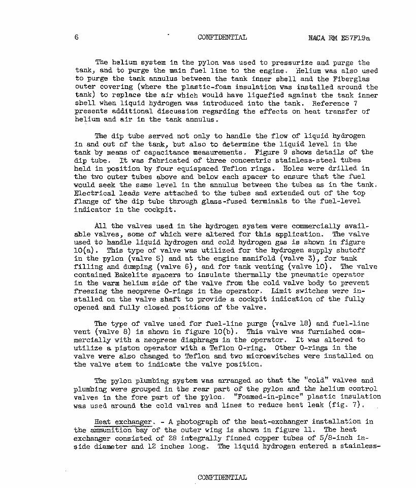
The helfum system i n the pylon was used to pressurize and purge the tank, and to purge the main f u e l l i n e t o the engine. Helium was also used t o purge the tank annulus between the tank inner s h e l l and the Fiberglas outer covering (where the p las t ic-f oam insulation was ins ta l led around the tank) t o replace the a i r which would have l iquefied against the tank inner s h e l l when l iquid hydrogen was introduced into the tank. Reference 7 presents additional discussion regarding the effects on heat t ransfer of helium and a i r fn the tank annulus.
The dip tube served not only t o handle the flow of l iquid hydrogen i n and out of the tank, but a l s o t o determine the l iqu id leve l i n the tank by means of capacitance measurements. Figure 9 shows de ta i l s of the d ip tube. It w a s fabricated of three concentric s t a in l e s s - s t ee l tubes held i n posi t ion by four equispaced Teflon rings. Holes were d r i l l e d i n t h e two outer tubes above and below each spacer t o ensure t h a t the f u e l would seek the same l eve l i n the annulus between the tubes as i n the tank. E lec t r i ca l leads were attached to the tubes and extended out of the top flange of the dip tube through glass-fused terminals t o the fuel- level indicator i n the cockpit.
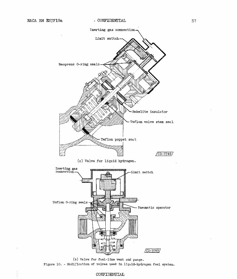
83-1 the valves used i n the hydrogen system were commercially avai l - able valves, some of which were a l te red f o r t h i s application. The valve used t o handle l i qu id hydrogen and cold hydrogen gas is shown i n f igure 10(a). This type of valve was u t i l i zed f o r the hydrogen supply shutoff i n the pylon (valve 5) and at the engine manif o ld (valve 3), f o r tank f i l l i n g and dumping (valve 6) , and f o r tank venting (valve 10) . The valve contained Bakelite spacers t o insulate thermally the pneumatic operator i n the w a r m helium side of the valve from the cold valve body t o prevent e e e z i n g the neoprene O-rings i n the operator, Limit switches were in- s t a l l e d on the valve shaf t t o provide a cockpit indication of the f u l l y opened and f u l l y closed posit ions of the valve.
The type of valve used f o r &el-line purge (valve 18) and fuel- l ine vent (valve 8) is shown i n f igure 10(b). This valve was furnished com- mercially with a neoprene diaphragm i n the operator. It was a l te red t o u t i l i z e a piston operator with a Teflon O-ring. Other O-rings i n the valve were a l so changed t o Teflon and two micraswitches were ins t a l l ed on the valve stem t o indicate the valve position.
The pylon plumbing system was arranged so t h a t t he "coldn valves and plumbing were grouped i n t h e r ea r p a t of the pylon and the helium control valves i n the fore par t of the pylon. "Foamed-in-placeq' p l a s t i c insulation was used around the cold valves and l ines t o reduce heat leak ( f ig . 7 ) .
Heat exchanger. - A photograph of the heat-exchanger installa+,lon i n the ammunition bay of the outer wing i s shown i n f igure 11. The heat exchanger consisted of 28 in tegra l ly finned copper tubes of 5/8-inch in- s ide diameter and 12 inches long. The l iqu id hydrogen entered a stainless-
CONFIDENTIAL

MACA RPIJ. E57F19a
s t e e l manifold on the bottom and passed through the finned tubes t o a s i m i l a r manifold on the top. The l iquid hydrogen w a s vaporized by ram air passing across the finned tubes. A de ta i led description of the heat exchanger along with discussion of i t s operation with hydrogen under simu- l a t ed a l t i t ude conditions is given i n reference 8.
A ram-air scoop was ins t a l l ed over the heat exchanger and fastened t o the wing s t ructure as shown i n figure 12. The ram-air duct was designed for a maximum airflow of 1.75 pounds per second for a f l i g h t Mach number of 0.72 a t 50,000 fee t . A mass airflow control f l a p was ins ta l led on the r e a r of the duct so that the ram-air flow could be r e s t r i c t ed when hydrogen w a s first introduced into the heat exchanger during f l i g h t i n order t o increase the r a t e of cool down t o the steady-state operating conditions.
Hydrogen regulator and J P f u e l system a l te ra t ion . - The hydrogen regulator is shown i n figure 13. It is essent ial ly a r a t i o control ler which u t i l i zes the normal JP f u e l flow f o r the engine t o control t he hy- drogen gas flow from the heat exchanger. Thus, during operation on hydro- gen, the JP f u e l flow requirement, as metered by the normal engine control system, is bypassed through the hydrogen regulator and discharged back t o the main JP h e 1 supply tank* The regulator has two p a r a l l e l flow passages, each containing a piston and o r i f i c e interconnected by a lever arm, A force proportional t o the metered JP f u e l flow is transmitted through the lever arm t o operate a variable-area valve i n t h e hydrogen s ide, The variable-area valve then meters enough hydrogen flow across the piston i n the hydrogen s ide t o balance the force from the JP f u e l s ide , I n addition, the hydrogen s ide of the regulator contains a temperature -compensating o r i f i ce tha t allaws increased volume flow of hydrogen gas during the i n i - tial period of operation when the en t i r e system is being cooled from the ambient temperature t o the equilibrium operating temperature of approxi- tzately 5p R. Reference 9 gives a complete discussion of the hydrogen- regulator design and operat ion.
A shutoff valve (valve 2) was provided i n the JP f u e l bypass l i n e as well as i n the main JP fue l l i n e t o the engine (valve 1) so thest the JP f u e l flow could be directed from the engine t o the hydrogen regulator when the change t o hydrogen fue l w a s made. An o r i f i ce w a s ins ta l led i n the JP fue l bypass l i n e t o match approximately the pressure drop i n the main JP f u e l l i n e t o the engine so t h a t JP f u e l flow through engine speed control would be within the governing range of the speed control when the engine fuel was changed t o hydrogen.
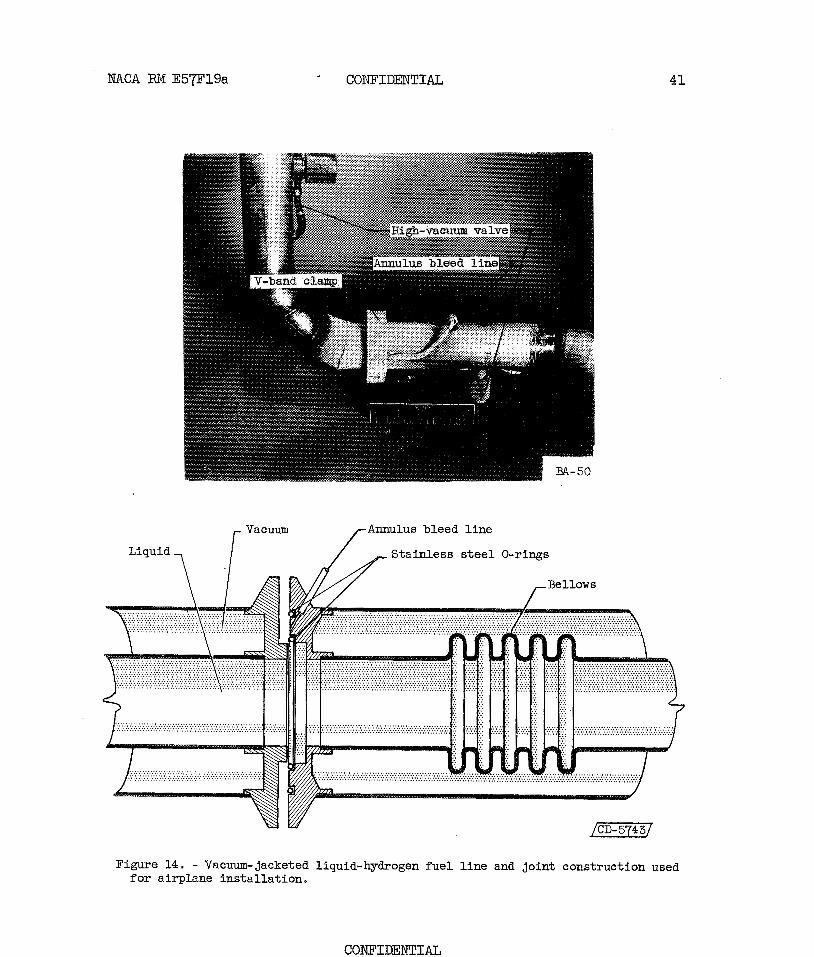
Fuel and vent l i nes . - Construction de ta i l s of the vacuum-jacketed l i n e that carr ied l iqu id hydrogen from the pylon t o the heat exchanger are shown i n f igure 14. This fue l l i n e was made up of two concentric s ta in less -s tee l tubes. The inner tube w a s 1 inch i n diameter and the outer tube 2 inches i n diameter. A bellows was i n s t a l l ed on the inner
CONFIDENTIAL

8 CONFIDENTIAL NACA RM E57F19a
l i n e t o accommodate contraction as the l i n e was cooled t o liquid-hydrogen temperature. Bakelite spacers held the inner tube concentric with the outer tube.
The flange construction f o r the spec ia l vacuum-jacketed l i n e is a lso shown on f igure 14. Two flat-f aced flanges containing a double hollow- metal O-ring seal were use& t o connect the l i n e sections. The flanges were held together by a V-band clamp. The annulus formed between the two O-rings was connected t o the fuel-tank vent tube so t h a t any leakage which might develop across the inner O-ring would be vented overboard. The f la t-f langed type of joint used is a higher-heat-leak joint than the bayonet-type joint commonly used i n cryogenic plumbing. However, the bayonet-type joint w a s not eas i ly adaptable t o the a i r c r a f t i n s t a l l a t ion because of space l imitat ions fo r assembly, and heat leak of the flanged joints was not objectionable.
The f'uel l i n e downstream of the heat exchanger f o r gaseous hydrogen contained the s m type of joint construction, but t h e l i n e was a single tube without provision f o r vacuum jacketing o r insulation.
!The vent system i n the pylon used t o vent hydrogen gas was constructed of sluminum tubing with machine-flared joints and standard a i r c r a f t f i t t i n g s .
Engine Modifications
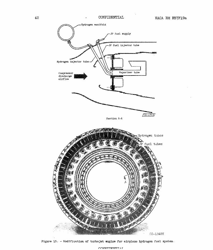
The bas ic engine modifications fo r use of hydrogen f'uel a re shown i n f igure 15. The JP f u e l is normally injected in to the engine through 114- inch-diameter tubes, which discharge into vaporizer tubes i n the engine combus t o r section. Similar 1/4-inch-diameter tubes were added f o r the introduction of hydrogen gas. A special A-inch-diameter s t a in l e s s - s t ee l
4 manif old w a s i n s t a l l ed around the engine and connected t o the inject ion tubes by means of standard f l ex ib le metal l ines . The gaseous hydrogen from the f u e l regulator was conducted d i rec t ly t o the manifold. Further de ta i l s regarding modification of the engine are given i n reference 10.
Helium System
The f u e l system required a supply of helium fo r valve operation and purge of the hydrogen tank and l ines . This helium supply was carr ied i n 24 Fiberglas spheres each with a volume of 880 cubic inches, which were charged t o a pressure of 3000 pounds per square inch and mounted i n a modified tank suspended from the r i g h t wingtip. A photograph of the tank
CONFIDENTIAL

N X A RM E57F19a * CONFIDENTIAL 9
mounted on the wingtip of the airplane is shown i n f igure 16. This in- s t a l l a t i o n also provided aerodynamic symmetry fo r the hydrogen f u e l tank mounted on the l e f t wingtip. Two of the 24 spheres were isolated from the common manifold fo r emergency use and could be made available by operation of explosively actuated valves (valves 17, f i g , 3) .
The pressure-regulating system (f ig . 3) reduced the supply pressure through appropriate pressure-reduc ing valves (valves 15 and 16) for purging and pressurization. A rupture disk w a s i n s t a l l ed i n the supply l i n e (pressure, 150 lb/sq in.) t o protect against overpressure due t o possible malfunctioning of the pressure regulators, and a r e l i e f valve (valve 14) w a s a l so incorporated i n se r i e s with the rupture disk t o pre- vent t o t a l loss of helium should the supply return t o normal a f t e r burst- ing the disk.
Fuel Loading
I n preparation f o r loading the wingtip tank with l iquid hydrogen, the a i r c r a f t was moved t o an area where the vent a t the rear t i p of the tank could be connected t o a special ground vent system. This vent system exhausted i n an open area well separated from the airplane s i t e and w a s located so tha t the gas would be vented i n a safe direction.
The vacuum- jacketed t ransfer l ine from the portable ground supply Dewar tank w a s attached t o the tank f i l l i n g connection located at the r ea r of the pylon ( f igs . 3 and 8) . With the t ransfer l i n e connected, the en- t i r e system, including the t ransfer l ine , the wingtip tank, and the ground vent l ines , w a s purged with helium gas by pressurization of the tank and exhausting of the gas through the ground vent system. The l iquid was then t ransferred from the Dewar tank t o the wingtip tank. During t h i s f i l l i n g period the vent remained open t o exhaust the boi loff gas well away from the airplane as the tank cooled and thus maintain essent ial ly atmospheric pressure i n the tank. Figure 17 shows the arrangement of equipment during the f i l l i n g procedure, Continuous leak checks of the pylon w e a were made during the f i l l i n g process with a portable combustible-gas analyzer.
When the tank was f i l l e d with hydrogen, the t ransfer l i n e and portable Dewar tank were removed. The tank was allowed t o vent a t atmospheric pres- sure u n t i l the engines were s t a r t e d with SP f u e l and the a i r c ra f t w a s ready for t ax i . A t that time, the vent valve was closed to allow pressurization of the tank t o begin, and the ground vent system was detached from the rear t i p of the tank. A previous fuel-tank investigation ( r e f . 11) had shown that venting of gas from the tank would not be required un t i l the airplane was airborne. This procedure of f i l l i n g and s tor ing the fue l eliminated the necessity for venting hydrogen gas near the airplane except

during the f l i g h t condit ion when su f f i c i en t a i r f low was ava i lab le t o pre- vent d i r e c t hydrogen contact wi th poss ible i gn i t i on sources on the a i rp lane .
During climb the f l i g h t engineer vented the tank as it approached maximum pressure by manually operating the vent valve. I n t h i s way s a f e tank pressures were maintained.
Transi t ion from JP Fuel t o Hydrogen
When t h e a i rp lane had reached t he c ru i se a l t i t u d e of approximately 50,000 f e e t , t r a n s i t i o n from engine operation with JP f u e l t o hydrogen w a s accomplished according t o the procedure es tabl ished i n previous t e s t - chamber s tud ies ( r e f . 1 0 ) . Each ste? was acconrplished i n a simple manner by systematic advancement of t he master switch on the r e a r cockpit con t ro l panel . This switching system was arranged t o accomplish the following s t ep s f o r each successive switch posit ion:
(1) Hydrogen fue l - l i ne and tank p ressur iza t ion with helium
(2) Helium purge of hydrogen f u e l l i n e
(3) Change t o dual f u e l operation (JP f u e l and hydrogen)
(4) Complete operation on hydrogen
When c ru i s e on hydrogen w a s complete, t r a n s i t i o n t o JP f u e l opera- t i o n was accomplished i n the following s teps :
(5) Change t o J P f u e l operation and hydrogen-line purge wi th helium
(6) Closing of hydrogen f u e l l i n e
(7) Dumping of r e s i dua l f u e l i n tank
( 8 ) Pressur izat ion of hydrogen tank w i th helium
Obviously, t o accomplish these t r a n s i t i o n s teps , multiple-valve operations were required f o r most of the master-switch pos i t ions . I n order t o ensure t h a t each valve i n t he system was functioning properly f o r each sequence posi t ion, an ind ica t ing l i g h t w a s i n s t a l l e d above t h e master switch f o r each c r i t i c a l valve ( f i g . 5 ) . The e l e c t r i c c i r c u i t was arranged s o t h a t f o r each master switch pos i t i on the l i g h t w a s "on" when t h e valve represented by it was i n t h e cor rec t opened o r closed pos i t ion , These valve l i g h t s were actuated d i r e c t l y from t h e microswitches mounted on valve stems, as described i n t h e sec t ion "Valving and plumbing", s o that t h e l i g h t indicat ions represented ac tua l mechanical movements of t he valves

- The master switch w a s advanced alve 18, f ig s . 3 and 8) w a s thereby
opened, and then the pressure w a s adjusted ( v k v e Ts) t o 5 pounds per square inch above the compressor-discharge pressure. '.BE tank was pres- surized with helium gas t o 50 pounds per square inch by merely adjusting the tank purge pressure reducer (valve 11) t o the proper pressure.
Purge of hydrogen f u e l l i ne . - By advancing the master switch t o posit ion 2 , with the engine operating on JP fue l , the hydrogen manifold valve (valve 3) was opened t o allow a flow of helium gas through the hy- drogen fue l l i ne and direct ly in to the engine. The helium pressure w a s then increased (valve 13) t o 50 pounds per square inch f o r approximately
1$ minutes, which w a s considered suf f ic ien t time t o purge a l l air from the hydrogen fue l system.
Dual f u e l operation. - Af'ter t he hydrogen fue l l i n e w a s purged with helium gas, the master control switch w a s advanced t o the next posit ion t o accomplish the following simultaneously:
(1) Close the hydrogen-f'uel-line purge valve (valve l8)
(2) Open the hydrogen-fuel-supply valve (valve 5)
(3) Open the JP fue l valve t o the hydrogen regulator (valve 2)
This valve action simultaneously provided i n i t i a l hydrogen f l a w t o the engine and provided JP fue l flow through the hydrogen f u e l regulator in addition t o the normal JP fuel f l o w t o the engine. This condition of dual f u e l operation was maintained u n t i l the hydrogen f u e l system had cooled t o a s tabi l ized temperature.
Operation on hydrogen fue l . - When operation had s tab i l ized at the dual f u e l condition, the next s t ep merely closed the JP f u e l manifold valve (valve 1) and thus terminated the JP f u e l flow t o the engine. Under t h i s condition of operation, the en t i r e JP f u e l flaw from the engine-speed control passes through the hydrogen regulator back t o the main JP f u e l tank and serves t o regulate engine speed by controll ing the quantity of gaseous hydrogen passing through t h e regulator t o the engine.
Change from hydrogen t o JP fuel . - To change back t o JP fue l the previously described process w a s reversed, except tha t the two-step opera- t i o n required t o change t o hydrogen fuel ( to a t t a i n s tab i l iza t ion a f t e r cool down) could be accomplished i n one step. Thds, the next advancement of the master control switch simultaneously
(1) Shut off JP f u e l flow t o the hydrogen regulator (valve 2)
(2) Opened JT fue l flow t o t h e engine (val've 1)

(3) Closed the hydrogen supply (valve 5)
(4) Opened the hydrogen-fuel-line helium purge (valve 18)
After the hydrogen f u e l l i n e was adequately purged, the hydrogen manifold valve w a s closed (valve 3 ) .
Securing the f u e l tank. - To maintain as safe a system as possible before landing, the fue l tank was emptied and thoroughly purged. Any remaiiing l iqu id hydrogen was jett isoned through the vent-tube by opening the dump valve (valve 6 ) . A s m a l l amount of l iquid i n the bottom of the tank could not be jettisoned, since the dip tube extended t o within only 114 inch of the tank bottom. Therefore, the f i n a l helium purge during f l i g h t w a s delayed as long as feas ib le t o allow as much time as possible for the last remaining l iquid t o evaporate. During the tank-purging process care was exercised t o close the vent a t a presswe well above a%mospheric t o prevent possible backflow of a i r in to the tank, The tank was kept closed during the landing and t a x i per-iod. The airplane was re- turned t o the f u e l loading asea, where the ground vent system was attached and additional helium purges were accomplished.
Duridg these i n i t i a l f l i g h t studfes a number of safety measures were taken t h a t experience may show t o be unnecessary. However, i n these ear ly f l i g h t s an extremely cautious approach was used t o ensure, insofar as pos- s ib le , a safe operation.
Some of the safety precautions were incorporated in to the basic fue l - system design. These included the remote wingtip location fo r the f u e l tank and the provision fo r dropping the tank. The only major connection between the tank and the pylon was the s ingle dip-tube opening, This opening was sealed by means of a large metal bellows, which would rupture upon separation of the tank from the wing and allow the tank to drop f r e e of the dip tube which would remain with the pylon.
A combustible-gas-alarm system was ins t a l l ed t o monftor continuously four selected c r i t i c a l areas during the errtire ground and f l i g h t procedure. A simple schematic drawing of t h i s system f s shown i n figure 18. Samples were continuously drawn from the wingtip area, from each of the two ven- t i l a t i o n louvers i n the gun bays adjac'ent t o the ammunition bay, and from the engine compartment above the hydrogen-manifold connections. These samples were then cyclically passed through the gas a l a r m located i n the cockpit* The cycling function of the system was indicated t o the f l i g h t engineer by the zone l igh t s on the control panel ( f ig . 5 ) , and any sample containing a hydrogen concentration higher than 4Q percent of the lower explosive l i m i t would be indicated by the combustible-gas-alarm l i g h t on t h e panel.
CONFIDENTIAL
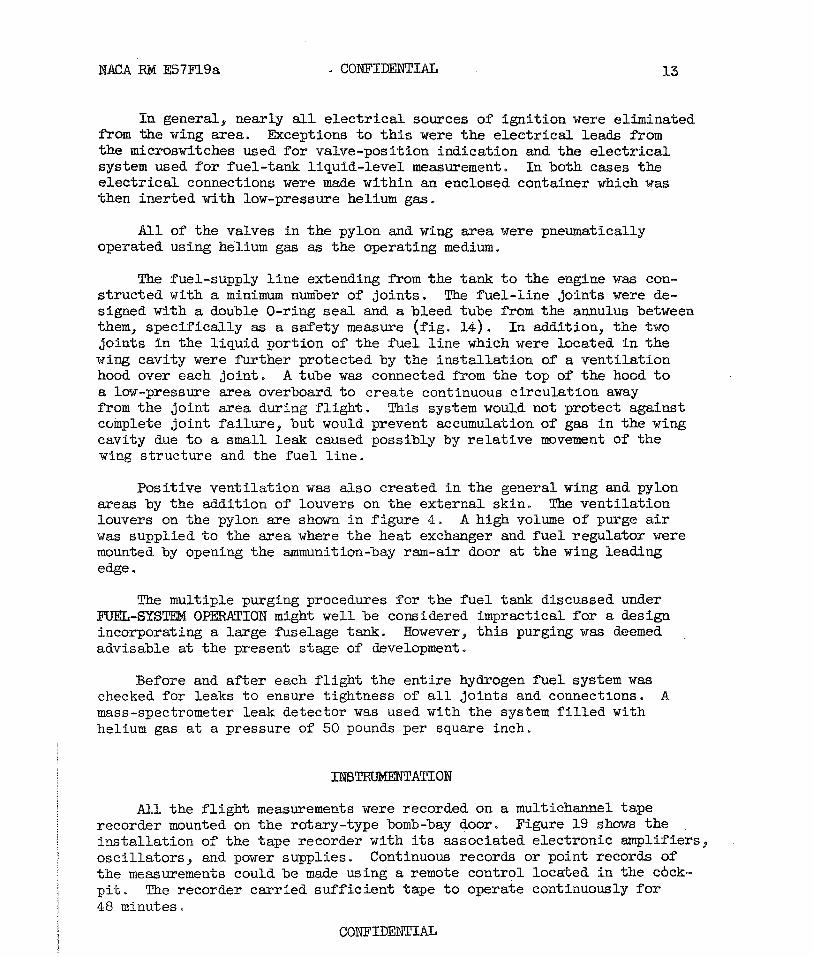
In general, nearly all e l e c t r i c a l sources of igni t ion were eliminated. from the wing area, Exceptions t o t h i s were the e l ec t r i ca l lea& from the microswitches used f o r valve-position indication and the e l ec t r i ca l system used f o r fuel-tank liquid-level measurement. In both cases the e l e c t r i c a l connections were W e within an enclosed container which was then iner ted with low-pressure helium gas.
A l l of the valves i n the pylon and wing area were pneumatically operated using helium gas as the operating medium.
The fuel-supply l i n e extending from the tank t o the engine w a s con- s t ructed with a minimum number of joints . The fue l - l ine joints were de- signed with a double O-ring s e a l and a bleed tube from the annulus between them, specif ical ly as a safety measure ( f ig , 14) , I n addition, the two joints i n the l iquid portion of the f u e l l i n e which were located i n the wing cavity were fur ther protected by the ins t a l l a t ion of a vent i la t ion hood over each joint . Atube was connected f2om the top of the hood t o a low-pressure area overboard t o create continuous circulat lon away from the joint area during f l i g h t . This system would not protect against complete joint fa i lure , but would prevent accumulation of gas i n the wing cavity due t o a small leak caused possibly by r e l a t ive movement of the wing s t ructure and the fue l l ine .
Posit ive vent i la t ion w a s also created i n t h e general wing and pylon areas by the addition of louvers on the external skin. The vent i la t ion louvers on the pylon are shown i n f igure 4. A high volume of purge air was supplied t o the area where the heat exchanger and f u e l regulator were mounted by opening the ammunition-bay ram-air door a t the wing ieadfng edge.
The multiple purging procedures fo r the f u e l tank discussed under FUEL-SYSm OPERCITIOE might well be considered impractical f o r a design incorporating a large f iselage tank* However, t h i s purging was kemed advisable a t the present stage of development.
Before and a f t e r each f l i g h t the en t i r e hydrogen f u e l system w a s checked for leaks t o ensure t ightness of a l l jo in ts and connections, A mass-spectrometer leak detector was used with the system f i l l e d with helium gas a t a pressure of 50 pounds per square inch,
All the f l i g h t measurements were recorded on a multichannel tape recorder mounted on the rotary-type bomb-bay door. Figure 19 shows the ins t a l l a t ion of the tape recorder with its associated electronic amplifiers, osc i l la tors , and power supplies. Continuous records or point records of the measurements could be made using a remote control located i n the cbck- p i t . The recorder carr ied su f f i c i en t tape t o operate continuously f o r 48 minutes.
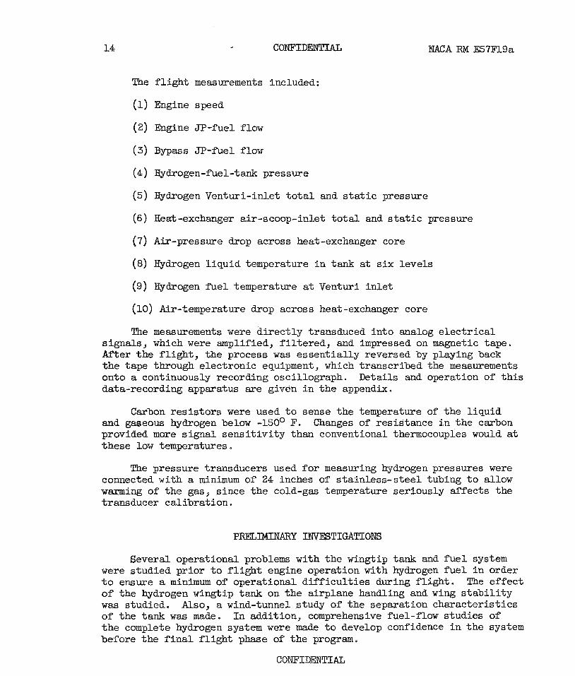
The f l i g h t measurements included:
(1) Engine speed
(2) Engine JP-fuel flow
(3) Bypass JP-fuel flow
(4) Hydrogen-fuel-tank pressure
(5) Hydrogen Venturi-inlet t o t a l and s t a t i c pressure
(6) Heat -exchanger air-scoop-inlet t o t a l and s t a t i c pressure
(7) Air-pressure drop across heat-exchanger core
(8) Hydrogen l iqu id temperature i n tank at s i x levels
(9) Hydrogen f u e l temperature at Venturi i n l e t
(10) Air -temperature drop across heat -exchanger core
The measurements were d i rec t ly transduced in to analog e l e c t r i c a l signals, which were amplified, f i l t e r e d , and impressed on magnetic tape, Af'ter the f l i g h t , the process was essent ia l ly reversed by playing back the tape through electronic equipment, which transcribed the measurements onto a continuously recording oscillograph. Details and operation of t h i s data-recording apparatus are given i n the appendix.
Carbon re s i s to r s were used t o sense the temperature of the l iquid and gaseous hydrogen below -150° F. Changes of resistance i n the carbon provided more s ignal s ens i t iv i ty than conventional thermocouples would at these low temperatures.
The pressure transducers used f o r measuring hydrogen pressures were connected with a minimum of 24 inches of s ta in less -s tee l tubing t o allow warming of the gas, since the cold-gas temperature seriously a f fec ts the transducer cal ibrat ion.
Several operational problems with the wingtip tank and f u e l system were studied pr ior t o f l i g h t engine operation with hydrogen f u e l i n order t o ensure a minimum of operational d i f f i c u l t i e s during f l i g h t . The e f fec t of the hydrogen wingtip tank on the airplane handling and wing s t a b i l i t y was studied. Also, a wind-tunnel study of the separation character is t ics of the tank was made. I n addition, comprehensive fuel-flow studies of the complete hydrogen system were made t o develop confidence i n the system before the f i n a l f l i g h t phase of the program.

BACA RM E57F19a
Airplane Handling and Wing Vibration
Several s i gn i f i c an t d i f ferences ex i s ted between t he hydrogen f u e l tank and t he JP wingtip tank normally used on t h e a i rp lane which necessi- t a t e d aerodynamic s tud ies . The hydrogen wingtip tank w a s much longer than t h e tank normally used on t h e a i rplane. It was 30 inches i n diameter and 23 f e e t long (outside dimensions), whereas t h e normal JP-fuel tank is 32 inches i n diameter and 14 f e e t long. The hydrogen tank w a s suspended from a pylon support, while t h e conventional tank nes t l es f l u s h with the bottom surface of the wingtip. The f u l l hydrogen f u e l tank, pylon, and plumbing weighed approximately 1000 pounds a s opposed t o the conventional f u l l - t ank weight of 2300 pounds.
Mockup f u e l tanks were subs t i t u t ed on t h e a i rp lane f o r t h e insu la ted tanks t o accomplish t h e i n i t i a l aerodynamic f l i g h t t e s t s . Figure 20 shows a mockup tank mounted on the a i rp lane wingtip. To preserve symmetry of balance and geometry, i d e n t i c a l mockup tanks were mounted on each wingtip. These tanks were b a l l m t e d t o simulate t h e weight and moment of i n e r t i a of the insu la ted hydrogen tank f i l l e d with f u e l .
The a i rplane w a s flown with and without t h e mockup wingtip tanks so t h a t t he p i l o t could compare handling cha rac t e r i s t i c s . After t h e p i l o t was s a t i s f i e d t h a t t he wingtip tank i n s t a l l a t i o n created no general han- d l ing problems, t he e f f e c t of t he mockup tanks and t he insu la ted tank on t he wing s t a b i l i t y w a s checked. Accelerometers were mounted on the wing- t i p and i n t he fuselage t o measure t h e wing v ib ra t ions , and a multichannel. t ape recorder connected t o accelerometer ampl i f iers continuously recorded each acce le ra t ion . The wing v ib ra t ions i n f l i g h t were exci ted by abruptly moving t he e levator controls . Although t he p i l o t experienced d i f f i c u l t y i n imposing g rea t enough change i n accelera t ion t o exc i t e t he wing i n t o a f r e e o s c i l l a t i o n by t h i s method, enough da ta po in t s were obtained t o show a s t a b i l i t y c r i t e r i o n within t h e proposed range of f l i g h t condit ions. The r e s u l t s indicated t h a t f o r t he range of f l i g h t conditions considered f o r t h i s a i rp lane the re was no c r i t i c a l wing f l u t t e r .
Tank Sepasat ion
A ca lcu la t ion of t h e forces on t h e tank i n its normal pos i t ion on t he wing, based on estimated aerodynamic eoeff i c i e n t s , indicated t h a t upon separat ion the nose of t he tank would yaw out and p i t ch up and t h a t t h e tank would t r a n s l a t e outward away from t h e wingtip.
A tank separat ion study was conducted i n a 6- by 9-foot wind tunnel with a 1/6-scale model t o ve r i fy these ca lcu la t~ ions . A semispan of the a i rplane wing w a s cant i levered from one s i de of t h e tunnel w a l l s o t h a t t h e tank model w a s located approximately on the cen te r l ine of t he tunnel t e s t sec t ion . The tank w a s constructed of wood and s t e e l t o simulate t h e correct scaled weight and moment of i n e r t i a ,
CONFIDENTIAL

CONFIIJENTIAL NACA Rlvr E57F19a
Tank separations were made f o r several f l i g h t conditions covering the fu l l - sca le range of airspeeds and associated angles of attack pro- posed f or the hydrogen f l i gh t investigation.
The wind-tunnel r e su l t s corroborated the estimated motion of the tank and f o r none of the simulated f l i g h t conditions d id the tank s t r i k e any part of the pylon or wing during separation. From these r e su l t s it w a s concluded t h a t it would not be necessary t o put s tab i l iz ing f ins on t h e tank.
Preliminary Fuel-System Flow Studies
Prior t o in s t a l l a t ion i n the airplane, the complete fue l system was assembled i n a laboratory f a c i l i t y and used t o operate the f l i g h t engine under simulated a l t i t ude conditions. Nearly all the operational design features were perfected during these operations. The changeover from JP f u e l t o hydrogen was made many times t o ensure r e l i a b i l i t y i n the opera- t i ona l technique. The r e su l t s of t h i s work m e reported i n d e t a i l i n reference 10.
Subsequent .to the 1aborat.ory functional t e s t s the fue l system w a s i n s t a l l ed i n the research airplane. The airplane was flown several times on JT fue l only, a f t e r which a nonburning flow check was conducted on the ground to verify tha t the system was leak proof and that the flow regulator operated sa t i s f ac to r i ly . The f u e l tank was f i l l e d with hydrogen and pressurized with helium gas as would be done during f l i g h t . Using the master control switch, the operator duplicated the f l i g h t procedure t o change from JP fue l t o hydrogen. The flow of hydrogen through the system merely bypassed the engine and w a s exhausted as a gas from the ground vent system well away from the airplane. The proper JP fue l flow through t h e regulator was established without engine operation, and the response of the regulator f o r proper control of hydrogen flow was sa t i s f ac to r i ly established. During the operational period with hydrogen, the en t i re system was checked for leaks.
The f i r s t f l i g h t s using the system consisted of dry runs without hydrogen fue l . The purpose was to check the operation of the coqonents
I at the a l t i t ude and f l i g h t conditions for which they were expected t o operate and t o t e s t operation of the JP f u e l b n a s s system. The fue l tank was f i l l e d with helium gas instead of hydrogen fue l . The f l i g h t engineer duplicated the exact changeover procedure tha t would be used f o r hydrogen fue l . Thus, when the system was switched to the dual f u e l posi t ion (as described under FUEL-SYSTEM OPERATION) engine speed dropped t o idle , since fue l from the hydrogen system was not available to the engine. O f course, when the system was switched t o f u l l hydrogen opera- t ion, the engine flamed out, but operation of valves i n the system could be established by t h i s procedure.

NACA RM E57F19a - CONFIDENTIAL
These f l i g h t s d id reveal a problem not previously discovered. The low temperature a t high a l t i t u d e s presented a d i f f i c u l t y with the helium- pressure-regulator valves i n the tank-pressurizing system. The ex i s t ing rubber diaphragms i n the valve became too s t i f f t o operate at the tank pressure of 55 pounds per square inch. They were replaced with 0.020- inch-thick neoprene-impregnated nylon-cloth diaphragms, which were exten- s ive ly t e s t ed i n t he laboratory a t dry-ice temperatures.
Leak checks were conducted on t he e n t i r e system a f t e r each f l i g h t using helium gas i n t h e system t o ensure t h a t gross wing f lexure and vibrat ion did not c rea te leaks .
FLIGHT PROCEDURE WITH HYDROGEN .FUEL
The f u e l system designed f o r t h i s f l i g h t invest igat ion was t o supply one a i rplane tu rbo je t engine with enough hydrogen f u e l t o operate fo r 20 t o 30 minutes at 98 percent of r a t e d speed a t an a l t i t u d e of 50,000 f e e t and a f l i g h t Mach number of 0.72. I n order t o s a t i s f y t h i s requirement, t he wingtip f u e l tank was constructed t o contain about 200 pounds of hy- drogen f u e l at takeoff . The a i rp lane took of f and climbed on JF' fue l t o 50,000 f e e t , where t he p i l o t s h i f t e d one engine over t o hydrogen f u e l . The t a x i , takeoff , and climb periods combined averaged about 55 minutes, which then cons t i tu ted the storage time of t he hydrogen f u e l on t he air- plane from the completion of fue l ing t o use i n t h e engine.
The climb and operation of t he engine on hydrogen was conducted over Lake Er ie . A "chase" a i rplane f lew beside the research a i rplane t o ob- t a i n motion p ic tu res and repor t v i sua l observations during t h e operation on hydrogen f u e l . These comments were received by both a ground s t a t i o n and t h e research a i rplane. The conversations between the a i rplanes and t he ground s t a t i o n were recorded on a tape recorder on t h e ground. The comments of the crew i n the research a i rplane were a l so recorded on the data tape recorder i n the a i rplane.
DISCUSSION OF RESULTS
Three f l i g h t s were made on which t h e whole supply of hydrogen f u e l was burned and t h e system functioned i n a completely sa t i s fac tory manner. D a t a were obtained t o show the e f f e c t s of t h e hydrogen f u e l on engine operation and on the performance of the major system components. Data were taken during changeover from JF' f u e l t o hydrogen and a l s o during s teady-s ta te operation and t h r o t t l e t r ans i en t s . I n addit ion, comparisons of fuel-storage da ta and heat-exchanger performance with ground f a c i l i t y r e s u l t s were obtained.
CONFIDENTIAL

CONFIDENTIAL
Fuel Venting
As described under FUEL-Smm OPERATION, the wingtip tank was closed after the liquid-hydrogen f i l l i n g procedure was completed and the airplane was ready f o r t ax i . When the design pressure was reached, the tank vent w a s opened and hydrogen gas escaped out the vent tube; th i s resul ted i n a loss of available fue l . Thus, the r a t e of pressure increase d i rec t ly affected the time the f u e l could be stored before venting was required (no-loss time). The r e su l t s presented i n reference 12 describe the e f f ec t of agi ta t ion of the l iquid on reducing the r a t e of pressure buildup. The da ta obtained during the f l i g h t investigation indicate tha t motion of the airplane during f l i g h t and part icular ly during the t a x i period caused enough agi tat ion to reduce the r a t e of pressure increase i n the tank sub- s t an t i a l ly . The data presented i n figure 21 compare tank pressure-time h is tor ies while the airplane w a s stationary and while it was taxiing. The vent was closed a t zero time. The sharp changes i n slope of the pressure-rise plot during t a x i are caused by varying degrees of fue l
agi ta t ion. During the 5b-minute taxiing period, which s t a r t ed immedi- 2 a t e ly a f t e r closing of the vent, the pressure reached 30 pounds per square inch absolute. By comparison, fo r the same period of time the stationary tank reached 50 pounds per square inch absolute, o r nearly the design pressure, It is interest ing t o note the sharp pressure r i s e s while the airplane was parked pr ior t o t&eoff and immediately upon being airborne. The slope of the pressure-rise plot during these periods approximately matches the slope of the stationary-tank curve.
The pressure-time his tory of the en t i r e no-loss period, which is the time beginning when the vent was i n i t i a l l y closed u n t i l the tank was first vented during climb, is shown i n f igure 22. In addition t o the change i n r a t e of pressure r i s e during t a x i described i n figure 21, the e f fec t of air turbulence and possibly, t o a lesser extent, the e f fec t of mild a i r - plane maneuvering are apparent on the airborne portion of the p lo t . For t h i s f l i g h t the no-loss period was 17L minutes,
2
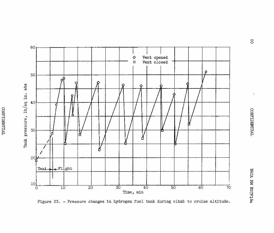
Atime history of the tank pressure f o r the complete climb period during another f l i g h t is shown i n f igure 23. These data show t h a t eight ventings were required during the 55 minutes of climb t o 50,000 f e e t , The pressure at which the vent was opened and closed was a rb i t r a r i ly selected by the f l i g h t engineer and obviously differed each time the tank was vented. The sharp pressure reduction a f t e r the f i r s t venting was caused by a moderate turbulence of the a i r and not by venting. This tur - bulence reduced the tank pressure from 42 t o 37 pounds per square inch absolute. These resu l t s indicate the importance of the e f fec t of agi ta t ion of the l iquid on the no-loss period and consequently on fue l l o s s ,
The f a c t t h a t agi ta t ion of the fue l tank causes s ignif icant reduction i n the r a t e of pressure r i s e indicates tha t the l iquid is not i n equilib- rium, The data presented i n figures 21 t o 23 i l l u s t r a t e tha t varying
CONFIDENTIAL

degrees of agi ta t ion correspondingly af fec t t h e pressure r i s e . Reference 1 2 describes t h i s e f fec t i n d e t a i l and shows t h a t violent agi ta t ion of l i qu id hydrogen i n a tank r e su l t s i n the pressure r i s e following very closely the calculated equilibrium pressure-temperature curve. During the f l i g h t investigation measurements were made of var iat ion i n tempera- t u r e of the l iquid between the bottom of the tank and the surface. Fig- ure 24 presents these temperature measurements plot ted against pressure compared t o the calculated equilibrium curve. A t the lower tank pressures (25 t o 30 lb/sq in.) the measured values approximate the theore t ica l values, but near the maximum tank pressure (55 lb/sq in .) t he measured temperatures are nearly 5O R below the equilibrium temperature. It is believed tha t at the surface of the l iquid pressure and temperature are i n f u l l e q u i l i b r i u ~ , but tha t the equilibrium layer is very thin. Thus, measurement of the l iquid temperature i n the controll ing surface would be extremely d i f f i cu l t , especially during f l igh t , when the l iquid is i n mot ion.
A continuous record of the quantity of f u e l i n the tank was made throughout the f l i g h t by use of the capacitance-type leve l indicator in- corporated with the dip tube. A time history of the f u e l quantity is shown i n f igure 25. When the vent w a s i n i t i a l l y closed the tank contained 207 pounds of fue l . When the airplane w a s at cruise a l t i t ude and the engine s t a r t ed t o operate on hydrogen, the tank contained 174 pounds of fue l . The venting losses amounted t o 33 pounds, or 16 percent of the i n i t i a l quantity. Data during the climb period are not shown because the airplane angle of attack caused the l iquid t o change leve l at the dip tube and introduced a large error .
Engine Speed and Tailpipe Temperature
Figure 26 shows the e f fec t of the f u e l t rans i t ion t o hydrogen on engine speed and t a i lp ipe temperature. During the first 1A minutes the
3 f u e l tank w a s pressurized with helium gas. Next the fue l l i n e w a s purged with helium gas. A t t h i s point the engine speed and ta i lp ipe temperature increased momentarily. This was caused by inject ion of a small amount of JP fuel, which flowed back from the vaporizer tubes into the hydrogen system during JP-fuel operation. The helium purge then forced t h i s Jl? f u e l into the combustor, where it enriched the mixture. During t h i s period the ta i lp ipe temperature momentarily increased to 650' C . This i s well below the established l i m i t of 800° C for a momentary peak temperature.
L The fue l l i n e was purged fo r approximately 1- minutes, a f t e r which 2
the engine was shif ted t o dual f u e l operation t o burn both JP fue l and hydrogen. To accomplish t h i s change, the JP-fuel flow w a s s p l i t (as de- scribed under FUEL-SYSTEM OPERATION) causing a momentary loss of JP fue l to the combustor. This resulted i n a s l igh t loss i n engine speed because
CONFIDENTIAL
hydrogen w a s not yet ava i l ab le t o the engine. The t h r o t t l e con t ro l sud- denly received an increased-demand JP flow t o maintain the s e t speed. Operation with the two f u e l s allowed the hydrogen system t o cool down t o an equil ibrium temperature p r i o r t o the courplete s h i f t t o hydrogen f u e l . This t r a n s i t i o n per iod w a s a r b i t r a r i l y es tabl ished t o l a s t 2 minutes; however, the engine would operate s a t i s f a c t o r i l y for an i nde f in i t e per iod using both f u e l s .
The switch t o complete hydrogen operation was made with no appreciable change i n engine speed o r t a i l p i p e temperature, and t h e engine functioned e n t i r e l y s a t i s f a c t o r i l y u n t i l t h e f u e l supply w a s exhausted ( for 21 min) . When t h i s became apparent t o the f l i g h t engineer, he switched d i r e c t l y back t o JP f u e l without incident . As the engine l o s t speed when the hydrogen supply was depleted, the f l i g h t engineer re tarded the t h r o t t l e before s h i f t i n g back t o JP f ue l ; then the engine accelera ted normally on JP f u e l t o the o r i g ina l speed,
Engine Response t o Thro t t l e S e t t i n g
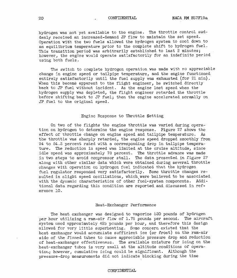
On two of t h e f l i g h t s t h e engine t h r o t t l e w a s va r ied during opera- t i o n on hydrogen t o determine t h e engine response. Figure 27 shows t h e e f f e c t of t h r o t t l e change on engine speed and t a i l p i p e temperature, As t h e t h r o t t l e w a s sharply re tarded, t h e engine speed dropped smoothly from 94 t o 84.5 percent r a t e d with a corresponding drop i n t a i l p i p e tempera.- t u r e . The reduction i n speed w a s l imi ted at t he c ru i s e a l t i t ude , s ince i d l e speed was approximately 78 percent , The t h r o t t l e advance w a s made i n two s t ep s t o avoid compressor s ta l l . The da t a presented i n f igure 27 along with other similar da t a which were obtained during severa l t h r o t t l e changes with operation on hydrogen f u e l indicated t h a t the hydrogen f u e l r egu la to r responded very s a t i s f a c t o r i l y . Some t h r o t t l e changes r e - s u l t e d i n s l i g h t speed o sc i l l a t i ons , which,were bel ieved t o be associa ted with t he dynamic cha rac t e r i s t i c s of other fuel-system components. Addi- t i o n a l da ta regarding t h i s condit ion m e repor ted and discussed i n r e f - erence 10.
Heat -Exchanger Performance
The heat exchanger was designed t o vaporize 520 pounds of hydrogen p e r hour u t i l i z i n g a ram-air flow of 1.75 pounds per second. The a i r c r a f t system used approximately 495 pounds per hour, and therefore t h i s design allowed f o r very l i t t l e superheating. Some concern ex i s ted t h a t the heat exchanger would accumulate s u f f i c i e n t i c e (o r f r o s t ) on t h e ram-air s i d e of t h e f inned tubes t o cause appreciable pressure drop and reduction of heat-exchanger e f fec t iveness* The ava i lab le moisture f o r i c i n g on t h e heat-exchanger tubes is very small at the a l t i t u d e conditions of opera- tior,; however, cumulative i c i n g could be s i gn i f i c an t . Although t h e pressure-drop measurements d i d not ind ica te blocking during t h e time

hydrogen was passing through the heat exchanger, no visual. &ata were ob- tained during these f l i g h t s t o ver i fy the absence of ice ox f r o s t on the tubes -
Figure 28 shows a comparison of the rm-air-temperature drop with hydrogen f u e l flow between the f l i g h t data and the laboratory f a c i l i t y data. The f l i g h t data indicate higher air-temperature drops or improved heat-exchanger effectiveness than the laboratory data for the same a i r - flow. This may be due t o lower heat-leak losses i n the f l i g h t in s t allat ion.
Condensation Tra i l s
The photographs i n figure 29 show the t a i lp ipe exhausts from the two engines during f l i g h t when the l e f t engine was using hydrogen fue l and the r ight engine was using JF fue l . The hydrogen-burning engine developed a very dense and per i s ten t condensation t r a i l , while the other engine d id not produce a cont ra i l . The hydrogen cont ra i l extended rearward as far as could be observed by .the chase airplane.
Fuel Jet t isoning
Two f l i g h t s were conducted during which the s h i f t was sa t i s f ac to r i ly made t o hydrogen fue l , but a'flow res t r i c t ion of hydrogen f u e l prevented engine acceleration t o high speed. In those f l i g h t s the en t i re f u e l supply was jett isoned through the vent tube on the f u e l tank. Jet t isoning of the f u e l was believed t o be generally l e s s hazardous and l e s s of an operational problem than landing with hydrogen f u e l i n the wingtip tank, Figure 30 shows a photograph of the airplane while the fue l was being jettisoned. The ent i re quantity of approximately 200 pounds was emptied
1 i n about 2 7 ~ minutes. The f u e l formed a dense cloud, which disappeared
about 20 f e e t rearward of the vent-tube exhaust. This procedure w a s car r ied out without incident on both occasions.
SUMMARY OF RESULTS
Three completely successful f l i gh t s were made using a specially in- s t a l l e d hydrogen f u e l system f o r one engine of a twin-engine a i r c ra f t . The climb and descent portions of the f l i g h t were made using JP f u e l only. The hydrogen-burning portion of each f l i g h t a t an a l t i tude of approximately 50,000 f e e t las ted nearly 21 minutes and exhausted the available f u e l supply. Transitions t o hydrogen f u e l and back t o JP f u e l were made very sa t i s f ac to r i ly without serious e f fec ts on the engine. Operation on hydro- gen f u e l was excellent. Throttle changes were made i n a normal fashion.
Heavy condensation t r a i l s were observed from the hydrogen-burning engine, whereas there were none from the engine burning JP fuel .
On two additional f l i gh t s , l iqu id hydrogen was jettisoned from the f u e l tank without incident. Also, hydrogen vapor resul t ing from f u e l boi loff i n the tank was vented periodically from the tank. Pressure and temperature data taken i n the f u e l tank show that agi ta t ion of the l iquid during f l i g h t and part icular ly during t a x i substantially reduced the r a t e of fuel-tank pressure r i s e from the r a t e previously observed f o r the tank i n a stat ionary posit ion. Heat-exchanger data showed good agreement with simulated a l t i t ude data f o r ram-air pressure drop and general heat- exchanger effectiveness.
Lewis Flight Propulsion Laboratory National Advisory Committee f o r Aeronautics
Cleveland, Ohio, July 5, 1957

APPENDIX - FLIGHT lXSTRmATION FOR
LIQUID-HYDROGE3 FUEL SYSTEM
By Scot t H. Simpkinson and Jacob C. Moser
The instrumentation used f o r t h e f l i g h t invest igat ion consisted f o r t he most pa r t of modified standard equipment. I n addi t ion t o t he spec ia l data-recording system, several of t he modifications served a purpose par- t i cu l a r ly unique t o t he hydrogen system. These consisted of a fue l - leve l indicator f o r t h e tank, a spec ia l fuel-tank low-level indicator t o inform the f l i g h t engineer when the f u e l was nearly exhausted ( f i g . 5 ) , a fuel- exhausted indicator t o show when a l l the l i qu id was gas i f ied so t ha t tank purging could be completed, and a heat-exchanger fuel-exhaust-temperature indicator t o determine when the f u e l system had cooled down t o a s t ab i l i z ed temperature during i n i t i a l operation.
Fuel-Tank Liquid-Level Indicator
The fuel-tank l iquid- level indicator operated by means of capacitance measurements using multiple tubes of t h e dip tube as the sensing device. Two concentric s t e e l tubes e l e c t r i c a l l y insulated from a t h i r d outer tube formed t h e p l a t e s of t he condenser. The l i q u i d and gaseous hydrogen be- tween t h e tubes provided the var iab le d i a l e c t r i c , Thus, as the f u e l l eve l changed, the capacitance indicat ion on the f l i g h t engineer 's control panel r e f l ec t ed t h i s change. The range of a standard a i rc ra f t - type ca- pacitance liquid-level-measuring indicator was s e t t o u t i l i z e the dip-tube s ignal ,
Fuel-Tank Low-Level Indicator
A carbon r e s i s t o r was i n s t a l l ed near the bottom of the dip tube (314 i n . from the bottom of the tank) t o indicate when the f u e l was nearly exhausted. The r e s i s t o r sensed the change i n temperature between t h e l i qu id and the w a r m gas as t he l i q u i d surface passed t h i s point . The indicator used with t he carbon r e s i s t o r was a sens i t ive mill ivoltmeter connected across a bridge c i r c u i t containing the carbon res is tance. The bridge values were se lec ted t o give a gross noticeable def lect ion when the l i qu id l e v e l passed t he carbon r e s i s t o r .
Fuel-Exhausted Indicator
I n order t o determine when a l l the res idua l l i q u i d i n t he tank had gas i f i ed s o t h a t tank purging could be completed, a copper-constantan thermocouple was spot-welded t o t he external surface of the bottom of the
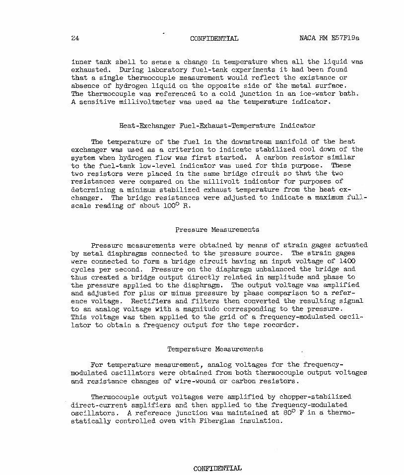
inner tank s h e l l t o sense a change i n temperature when a l l the l iqz id w a s exhausted. During laboratory fuel-tank experiments it had been found t h a t a s ingle thermocouple measurement would r e f l ec t the existance or absence of hydrogen l iquid on the opposite side of the metal surface. The thermocouple w a s referenced t o a cold junction i n an ice-water bath. A sensi t ive millivoltmeter w a s used as the temperature indicator.
Heat-Exchanger Fuel-Exhaust-Temperature Indicator
The temperature of the f u e l i n the downstream manifold of the heat exchanger was used as a c r i t e r ion t o indicate s tab i l ized cool down of the system when hydrogen flow was first s ta r ted . A carbon re s i s to r s i m i l a r t o the fuel-tank low-level indicator was used fo r t h i s purpose. These two re s i s to r s were placed i n the same bridge c i r cu i t so that the two resistances were compared on the mil l ivol t indicator f o r purposes of determining a minimum s tab i l i zed exhaust temperature from the heat ex- changer. The bridge resistances were adjusted t o indicate a maximum f u l l - scale reading of about loo0 R.
Pressure Measurements
Pressure measurements were obtained by means of s t r a i n gages actuated by metal diaphragms connected t o the pressure source. The s t r a i n gages were connected t o form a bridge c i r cu i t having an input voltage of 1400 cycles per second. Pressure on the diaphragm unbalanced the bridge and thus created a bridge output d i rec t ly re la ted i n amplitude and phase t o the pressure applied t o the diaphragm. The output voltage was amplified and adjusted fo r plus or minus pressure by phase comparison t o a re fer - ence voltage. Rect i f iers and f i l t e r s then converted the resul t ing s ignal t o an analog voltage with a magnitude corresponding t o the pressure. This voltage was then applied t o the gr id of a frequency-modulated osc i l - l a t o r t o obtain a frequency output f o r the tape recorder.
Temperature Measurements
For temperature measurement, analog voltages fo r the frequency- modulated osc i l l a to r s were obtained from both thermocouple output voltages and resistance changes of wire-wound or carbon re s i s to r s .
Thermocouple output voltages were amplified by chopper-stabilized direct-current amplifiers and then applied t o the frequency-modulated osc i l l a to r s . A reference junction was maintained a t 80° F i n CA thermo- s t a t i c a l l y controlled oven with Fiberglas insulation.
MACA RM E57F19a CONFIDEEJTW 25
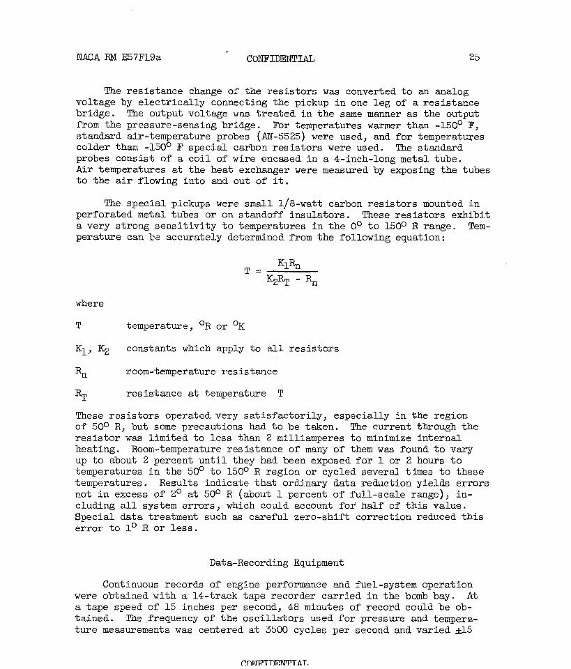
The resistance change of the res i s tors was converted t o an analog voltage by e lec t r ica l ly connecting the pickup i n one leg of a resistance bridge. The output voltage was t reated i n the same manner as the output from the pressure-sensing bridge. For temperatures w m e r than -150' F, standard air-temperature probes (AM-5525) were used, and fo r temperatures colder than -150° F special carbon res i s tors were used. The standard probes consist of a c o i l of wire encased i n a 4-inch-long metal tube. A i r temperatures a t the heat exchanger were measured by exposing the tubes t o the air flowing into and out of it.
The special pickups were small 1/8-watt carbon res i s tors mounted i n perforated metal tubes or on standoff insulators. These r e s i s to r s exhibit a very strong sens i t iv i ty t o temperatures i n the o0 t o 150° R range. Tem- perature can be accurately determined from the following equation:
where
T temperature, OR or OK
K1, K2 constants which apply t o a l l r e s i s to r s
'n room-temperature resistance
R~ resistance at temperature T
These r e s i s to r s operated very sa t i s fac tor i ly , especially i n the region of 50° R, but some precautions had t o be taken. The current through the r e s i s to r was l imited t o less than 2 milliamperes t o minimize internal heating. Room-temperature resistance of many of them w a s found t o vary up t o about 2 percent u n t i l they had been exposed f o r 1 or 2 hours t o temperatures i n the 50' t o 150° R region or cycled several times t o these temperatures . Results indicate tha t ordinary data reduction yields errors not i n excess of 2' a t SO0 R (about 1 percent of ful l -scale range), in- cluding a l l system errors , which could account f o r half of t h i s value. Special data treatment such as careful zero-shift correction reduced t h i s e r ror t o lo R or l e s s .
Data-Recording Equipment
Continuous records of engine performance and fuel-system operation were obtained with a 14-track tape recorder carr ied i n the bomb bay. A t a tape speed of 15 inches per second, 48 minutes of record could be ob- tained. The frequency of the osc i l la tors used for pressure and tempera- tu re measurements was centered a t 3500 cycles per second and varied d 5
f!nN??TTIli!NrPT AT.

percent by fu l l - sca le changes i n pressure and temperature. Reference da ta or zero levels t o obtain absolute values were established by ca l i - bration. The f u e l flow and engine speed were measured by variable- frequency generators. The frequency of the output voltage was varied by changes i n the measured quantity.
One track of the tape recorder was s e t aside t o record the voices of the p i lo t , the f l i g h t engineer, and the ground-station operator for purposes of adding to the data and timing events, which could not otherwise be a c c o ~ l i s h e d .
This recorder provided excellent reproduction of signals, a l l errors being l e s s than 2 percent of fu l l - sca le range. Noise superimposed on s ignals and tape-speed variations were negligible.
Each frequency-modulated osc i l la tor was provided with a reference frequency, which was used during pref l ights as an index of the osc i l l a to r ' s serviceabi l i ty . The reference frequency was provided by removing the 1400-cycle-per-second exciting voltage from the temperature or pressure pickup. This was equivalent t o having a balanced e l ec t r i ca l bridge and, when used i n f l i g h t , provided the zero-shift compensation data tha t were used i n the processing procedure. This reference calibration was actuated by the f l i g h t engineer every 15 minutes i n f l i g h t .
A l l pressure transducers were calibrated by d i rec t application of pressure, which was plot ted against the corresponding frequency of i t s associated osc i l l a to r . Temperature-controlled osc i l la tors were cal ibrated by subs t i tu t ion of known res i s to r s f o r the resistance probes. For wire- r e s i s t o r temperature probes the resistance-temperature re la t ion was deter - mined by cooling the r e s i s to r s a t boiling-hydrogen and boiling-nitrogen temperatures.
After a f l i g h t the tape was played back through a companion data reproducer. The frequency-modulated signals were amplified, f i l t e r e d ( i f multiplexed), and converted t o analog voltages, which were recorded by an os c illograph.
In general, traceable errors did not exceed 1 percent of fu l l - sca le range of the instruments. The frequency response of the reproduced data was l imited t o 11 cycles per second by the oscillograph galvanometer elements.

NACA RM E57F19a
1. Silverstein, Abe, and H a l l , Eldon W.: Liquid Hydrogen as a J e t Fuel f o r High-Altitude Aircraft . NACA IM E55C28a7 1955.
2. Jonash, Edmund R . , Smith, Arthur L., and mavin, Vincent F.: Low- Pressure Performance of a Tubular Combustor with Gaseous Hydrogen. NACA FB E54L30a, 1955.
3. Straight , David M., Smith, Arthur L., and Christenson, Harold H.: Brief Studies of Turbojet Combustor and Fuel-System Operation with Hydrogen Fuel at -400° F. NACA RM E56KZ7a7 1956.
4. Rayle, Waren D., Jones, Robert E., and Friedman, Robert: Experimental Evaluation of "Swirl-Can" Elements fo r Hydrogen-Fuel Combustor. NACA RM E57C18, 1957.
5 . Sivo, Joseph N., and Fenn, David B.: Performance of a Short Combustor at High Altitudes Using Hydrogen Fuel. NACA RM E56D24, 1956.
6. Reynolds, T. W.: Aircraf't-Fuel-Tank Design fo r Liquid Hydrogen. NACA RM E55F22, 1955.
7 . Lewis Laboratory Staf f : Hydrogen fo r Turbo j e t and Ramjet Powered Fl ight . W A R M E57D23, 1957.
8. Fenn, David B., Braithwaite, W i l l i s M. , and Ordin, Paul Me: Eesign and Performance of Flight-Type Liquid-Hydrogen Heat Ekchanger. NACA RM E57F14, 1957,
9 . 0 t t 0 , E d w a r d W . , H i 1 1 e r , K i r b y 7 W . , a n d R 0 s s , P h i 1 S . : Designand Performance of Fuel Control fo r Aircraft Hydrogen Fuel System. NACA RM E57F19, 1957.
10. Braithwaite, W i l l i s M., Fenn, Dayid B., and Algranti, Joseph S.: Altitude-Chamber Evaluation of an Aircraft Liquid-Hydrogen Fuel System Used With A Turbojet Engine. NACA RM E57F13a7 1957.
11. Reynolds, Thaine W. , and Weiss, Solomon: Experimental Study of Foam- Insulated Liquef ied-Gas Tanks. N E A RM E56K08a7 1957.
*
Heliuni tank P H I
F
Ffgure 1. - Airplane used for liquid-hydrogen flight investigation,

- . - -- - - - -
Figure 2. - General arrangement of liquid-hydrogen fue l system on airplane.

Figure 3. - Schematic diagram of a i r c ra f t hydrogen f u e l system.

I - Figure 4, - Liquid-~dlrogen f u e l tank in s t a l l ed on ai rplane wiagtfp,

.-
Figure 5 , - Hydrogen-system control panel i n airplane,

Rupture disk opening
Dip-tube opening
Support U-bolt
4-Ply Fiberglas
0,0025-Inch aluminum f o i l
P las t i c insulat ion
Circumferential
Figure 6. - Details of liquid-hydrogen-tank construction.

- -
Figure 7.. - Fuel-Lank pyfcn an a m l a n e with imsulatfon arou~d hydrogen plumbing,

Main fuel-supply l ine
Tank f i l l connection
Fuel-line re l ief
Tank f i l l and dump l ine
Figure 8. - Elydrogen syatem in fuel-tank pylon.

Vent holes
Figure 9. - Hydrogen-fuel-tank dip tube,
I n e r t i n g gas connection
\
( a ) Valve f o r l i q u i d hydrogen.
Inerting gas connection Limit switch
Teflon O-ring sea
Pneumatic operator
/-/
(b) Valve f o r fuel- l ine vent and purge.
Figure 10. - Modification of valves used i n liquid-hydrogen fue l system.
CONFIDENTIAL

Pigure 11, - Hydrogen heat exchanger mounted i n airplane ammunition bay. r'
, tD"

' 0.1 Figure 12, - Ram-air scoop for liquid-hydrogen heat excharger, CD

CONFIDENTIAL XACA RM E57Fl%
Figure 13. - Hydrogen-fuel-supply regulator f o r a i r c r a f t system.
PnNli'mFR~T A T.
NACA RM E5v19a + CONFIDENTIAL
Annulus bleed line
Stainless steel O-rings
/-
Figure 14. - Vacuum-jacketed liquid-hydrogen fuel line and joint construction used for airplane installation.
r=Y- Hydrogen manifold
,- JP f u e l supply
/-/ Section A-A
Ffgme 15. - Modlfleation of tmbsJo-t engfne for alzpplane h,ydro@n fuel sys'cem,
PAXTWTPWTIT~T f\T

Figure 16, - Helium supply tank used for airplane Wdrogen fuel s~s tem.
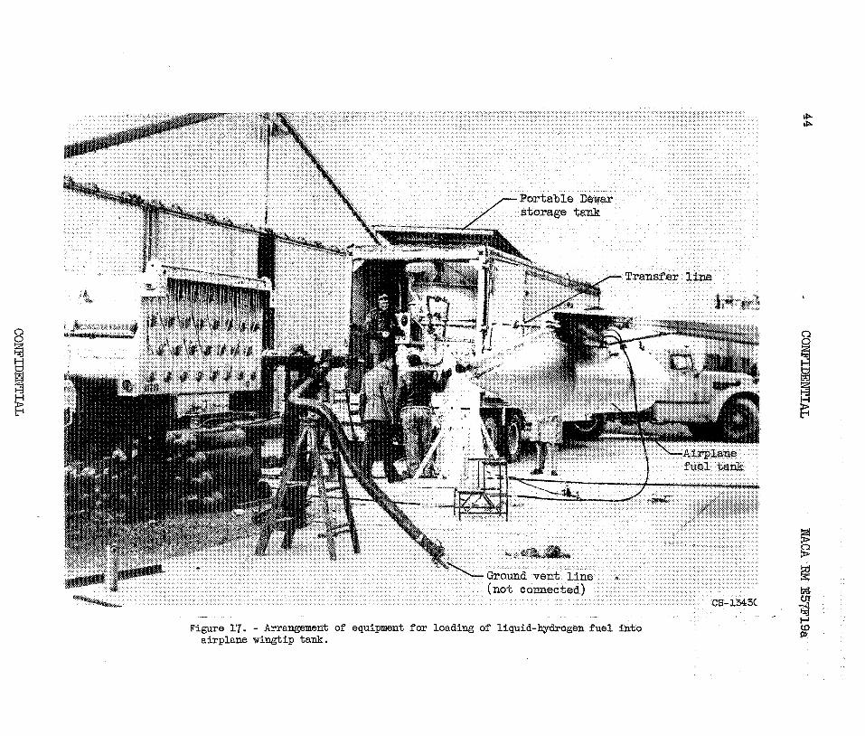
-- - Figure 17. - Arrangement of equipment for loading of liquid-hydrogen fue l into
- g airplane wingtip tank. 8

Figure 18. - Arrangement of combustible gas-alarm equipment for airplane hydrogen system.

Figure 19, - Multichannel data-recording system mounted on bornb-bay door of airplane.
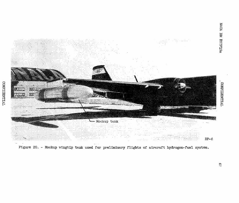
Figure 20, - Mockup vfn&Lp -tank used f o r prelimfmry f l f g h t s of a i r c r a f t hlydmgogen-fuel system,

Time, min 8 Figure 21. - Comparison of pressure rise in aircraft hydrogen-fuel tank before and d
P
during taxi. bl'

Time, min
Figure 22. - Time h i s t o r y of hydrogen-fuel-tank pressure r i s e during t a x i and i n i t i a l period of climb preceding f i r s t tank venting.
Time, min
Figure 23. - Pressure changes in hydrogen fuel tank during climb to cruise altitude,

liquid hydrogen
Temperature, OR
Figwe 24. - Comparison of liquid-hydrogen temperature and pressure in fuel tank with equilibrium curve.

240
200
160
120
80
4 0
0 Time, min
Figure 25. - Time h i s to ry of f u e l weight i n hydrogen tank.

Figure 26. - Engine speed and exhaust-gas temperature during transition from JP fuel to hydrogen during flight.

Exhaust-gas
temperature, OC
Throttle
position
c3
0
t-' 'd
0
GI 1
I

Hydrogen flow, lb/hr
Figure 28. - Comparison of performance of hydrogen-vaporizing heat exchanger during flight with performance in altitude facility.

COWIDENTIAL NACA RM E57F3
gure 29. - Contrails from engine operating on hydrogen fuel. A l t i t ~ 48,000 feet; Mach number, Oe70.
ade ,

CONFIDENTIAL
Figure 30. - Je t t i son of l iqu id hydrogen from f u e l tank. Altitude, 44,000 fee t ; Mach number, 0.70.
CONFIDENTIAI, NACA - Langley Field, Va.

![ÌQ WHPHLXO DUW OLW E DUW DOLQ DUW DOLQ ,L ,L DUW DOLQ … · 2018-01-22 · duw dolq ,l glq /hjhd qu sulylqg uhjlpxo lqiudvwuxfwxull il]lfh d uh .hohoru gh frpxqlfd .ll hohfwurqlfh](https://img.pdfslide.net/doc/110x75/5e7ccc0f1c67e900762cb24c/oeq-whphlxo-duw-olw-e-duw-dolq-duw-dolq-l-l-duw-dolq-2018-01-22-duw-dolq-l.jpg)


![&RQGL]LRQH JLXULGLFD GHO FLWWDGLQR H GHOOR … · sduwlwl duw shwl]lrqh duw yrwr duw dffhvvr d xiilfl sxeeolflhfdulfkhhohwwlyh duw &rqgl]lrqh jlxulglfd gho flwwdglqr h ghoor vwudqlhur3uri](https://img.pdfslide.net/doc/110x75/5e7ccc2a1c67e900762cb2ce/rqgllrqh-jlxulglfd-gho-flwwdglqr-h-ghoor-sduwlwl-duw-shwllrqh-duw-yrwr-duw.jpg)


![DUW 01 [tryb zgodności]](https://img.pdfslide.net/doc/110x75/586c69481a28ab237a8bb7dc/duw-01-tryb-zgodnosci.jpg)