Embed Size (px)
Citation preview
LEGACY REPORT
Business/Regional Office # 5360 Workman Mill Road, Whittier, California 90601 # (562) 699-0543Regional Office # 900 Montclair Road, Suite A, Birmingham, Alabama 35213 # (205) 599-9800Regional Office# 4051 West Flossmoor Road, Country Club Hills, Illinois 60478 # (708) 799-2305
ICC Evaluation Service, Inc.www.icc-es.org
Legacy report on the 1997 Uniform Building Code™
ER-4898Reissued January 1, 2004
Copyright © 2004Page 1 of 14
ICC-ES legacy reports are not to be construed as representing aesthetics or any other attributes not specifically addressed, nor are they to be construed as
an endorsement of the subject of the report or a recommendation for its use. There is no warranty by ICC Evaluation Service, Inc., express or implied, as to
any finding or other matter in this report, or as to any product covered by the report.
DIVISION: 07—THERMAL AND MOISTURE PROTECTIONSection: 07240—Exterior Insulation and Finish Systems
AKROFLEX EXTERIOR INSULATION AND FINISHSYSTEMS
OMEGA PRODUCTS INTERNATIONAL, INC.1681 CALIFORNIA AVENUECORONA, CALIFORNIA 92881
1.0 SUBJECT
Akroflex Exterior Insulation and Finish Systems.
2.0 DESCRIPTION
2.1 General:
2.1.1 Akroflex Exterior Insulation and Finish Systems:The Akroflex exterior insulation and finish systems areexterior wall coverings that are adhesively or mechanicallyattached to substrates of exterior walls of concrete orconcrete masonry, or water-resistant core gypsum sheathing,Dens-Glass™ Gold board, Durock fiber cement board,exterior grade plywood or Exposure 1 grade oriented strandboard (OSB) over steel or wood studs. Sections 2.1.2 and2.1.3 describe the two basic systems.
2.1.2 EIFS Without Drainage Provisions: The exteriorinsulation and finish system (EIFS) is adhered to verticalsubstrates of concrete masonry; concrete; or OSB, plywood,or water-resistant core gypsum sheathing over steel or woodframing. See Section 2.3.1. The system may also be installedwith the insulation board mechanically attached to concreteand masonry substrates in accordance with Section 2.3.3. Aweather-resistive barrier may be included for installations ofthe system mechanically attached to concrete and masonrysubstrates. The system components are an adhesive/basecoat, expanded polystyrene insulation board, reinforcingfabric, primer and a finish coat. The EIFS without drainageprovisions is not permitted to be installed on framed walls ofstructures of Type V, Group R, Division 1 or 3, Occupanciesunder the 1997 Uniform Building Code™ (UBC). The systemis permitted on walls required to be of noncombustibleconstruction when installed in accordance with Section 2.4.
2.1.3 EIFS With Drainage Provisions: The EIFS withprovisions for water drainage is a mechanically attachedsystem installed over vertical substrates of plywood, OSB,Dens-Glass Gold, gypsum sheathing or Durock cement boardover steel or wood framing in accordance with Section 2.3.2.The system components are a weather-resistive barrier,corrugated expanded polystyrene (EPS) foam plastic
insulation, reinforcing fabric, base coat, a finish coat and aweep screed starter track. This system is limited to installationin Type V construction including Group R, Division 1 andDivision 3, Occupancies under the UBC.
The weather-resistive barrier is as described in Section2.2.6. The weep screed starter track is as described inSection 2.2.7.
2.2 Materials:
2.2.1 Adhesive and Base Coat Mixes: The adhesive mixesadhere the insulation board to the substrate. The base coatmixes are used as the base coat for the systems. The mixesand their uses are described as follows:
2.2.1.1 Styro-Glue: Styro-Glue is an acrylic-based liquidproduct to which Type I-II low alkali portland cement,complying with ASTM C 150, is added at the jobsite, in theratio of one part Styro-Glue to one part cement by volume.The mixture is used both as an adhesive and a base coat.Styro-Glue is supplied in 5-gallon (18.9 L) containers and hasa one-year shelf life when stored in a cool, dry location.
2.2.1.2 Styro-Glue Dry Bond: Styro-Glue Dry Bond is aprepackaged dry mixture of portland cement complying withASTM C 150, sand and powdered acrylic admixture.Approximately 1 gallon (3.8 L) of water is added to each sackto achieve the desired consistency. The mixture is used bothas an adhesive and a base coat. The mix is supplied in 50-pound (22.7 kg) paper sacks and has a one-year shelf lifewhen stored in a cool, dry location.
2.2.1.3 Styro-Bond: Styro-Bond is an acrylic,noncementitious, liquid adhesive that can be used directlyfrom the container for the adhesive attachment of insulationboard to OSB and plywood substrates. Supplied in 5-gallon(18.9 L) containers, Styro-Bond has a shelf life of one yearwhen stored in a cool, dry location.
2.2.1.4 Styro-Glue TF is an acrylic, noncementitious, liquidbase coat, for the placement of glass fiber webbing as areinforced basecoat, that is used directly from the container.Supplied in 5-gallon (18.9 L) containers, this product has ashelf life of one year when stored in a cool, dry location.
2.2.2 Insulation Board:
2.2.2.1 EIFS Without Drainage Provisions:
2.2.2.1.1 Adhesively Attached Systems: The insulationboard for adhesively attached systems described in Sections2.1.2 and 2.3.1 must be flat-faced, square edge, Type I EPSboard complying with ASTM C 578, with a nominal density of1 pound per cubic foot (16 kg/m3), a flame-spread rating of 25

Page 2 of 14 ER-4898
or less and a smoke-developed rating not exceeding 450. Theboard thicknesses range from 1 to 4 inches (25.4 to 102 mm).Acceptable EPS insulation boards are:
• AFM Corporation Type I WSG (NER-551).
• Falcon Foam, A Division of Atlas Roofing, Type I EWG (ER-4059).
• Premier Industries, Inc./dba Insulfoam, Insulfoam EIFSGrade (IEG) (ER-3414).
2.2.2.1.2 Mechanically Attached System: The insulationboard used in systems mechanically fastened to concrete andmasonry substrates in accordance with Section 2.3.3 must beEPS boards as described in Section 2.2.2.1.1, except theboard thickness range is 3/4 inch (19.1 mm) to 11/2 inches (38mm).
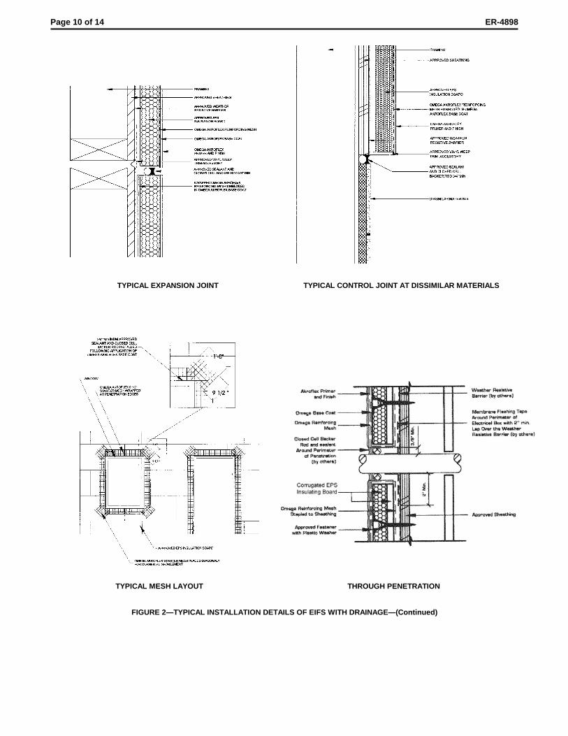
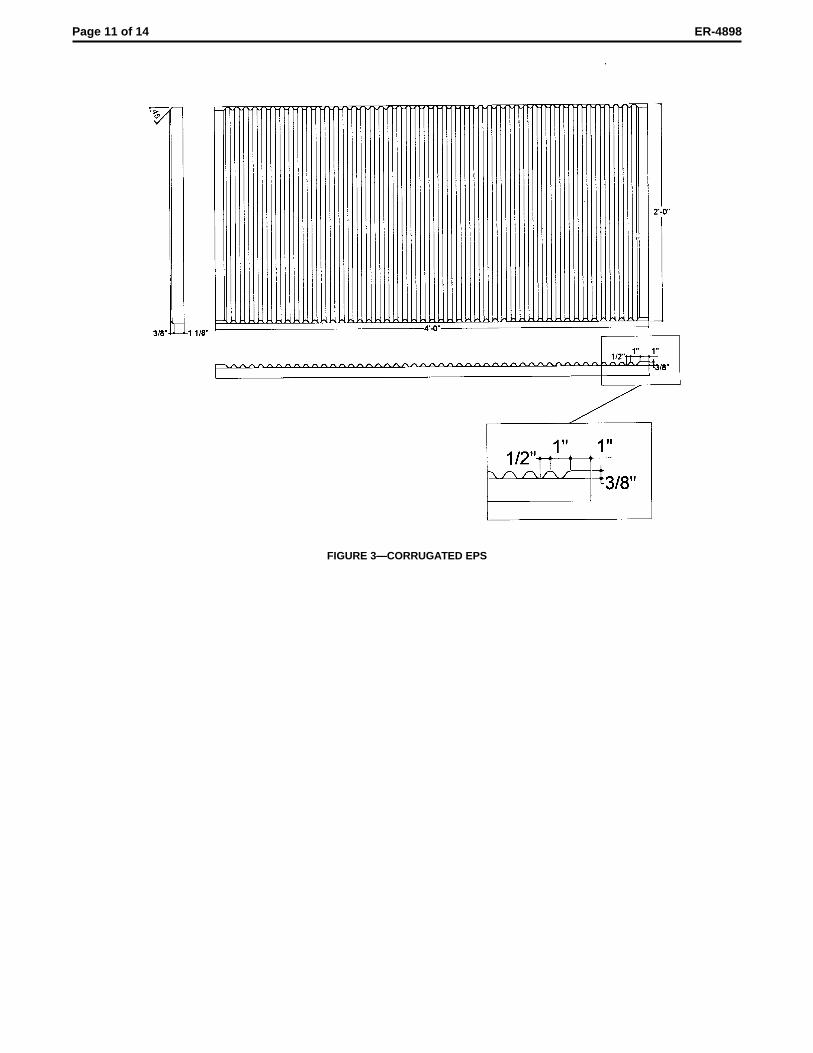
2.2.2.2 EIFS With Drainage Provisions: The insulationboard used in EIFS with drainage, described in Sections 2.1.3and 2.3.2, must be EPS boards as described in Section2.2.2.1.1, with the additional requirement that the boardshave a nominal thickness of 11/2 inches (38 mm) and 3/8-inch-deep (9.5 mm) corrugations spaced 1 inch (25.4 mm) oncenter on the back side of the board in accordance withFigure 3.
2.2.3 Reinforcing Fabric: The reinforcing fabric isULTRAFLEX, style 1350, manufactured by JPS Glass. Thefabric is an open-weave glass fiber of twisted multi-endstrands placed approximately 3/16 inch (4.8 mm) on centereach way and weighing approximately 4.5 ounces per squareyard (153 g/m2). The fibers are treated for alkali resistance.
2.2.4 Primer: Akroflex stucco primer is a pure acrylicemulsion binder and quartz sand mix. The primer has a shelflife of one year when stored in a cool, dry location.
2.2.5 Finish Coat: Akroflex acrylic finish is a proprietary,premixed, pure-acrylic-based, textured wall coating withgraded quartz aggregate. The finish coat has a shelf life ofone year when stored in a cool, dry location.
2.2.6 Weather-resistive Barrier: A weather-resistive barrieris required for installation on framed construction of Type V,Group R, Division 1 and 3, Occupancies under the UBC. Twolayers of Grade D kraft building paper complying with UBCStandard 14-1, or one layer of Grade D kraft building paperwith a 60-minute water-resistance rating, is required. Theweather-resistive barrier must be placed over the sheathing,and behind the insulation board. Application of the barriermust comply with UBC Sections 1402.1 and 2506.4. SeeSections 2.1.3 and 2.3.2 for a description of the systemrequiring the weather-resistive barrier.
2.2.7 Weep Screed Starter Track: The weep screed startertrack is the Moisture Management “332" PB Starter CasingBead, J-shaped, vinyl plastic track manufactured by VinylCorp. with 23/4-inch (70 mm) mounting flange and front andback weep holes in the bottom of the track which provide 3.53square inches of drainage area per foot (7.47 mm2/mm) oftrack length.
2.2.8 Mechanical Fasteners: Wind-Devil fastenersmanufactured by Wind-Lock are polypropylene, 13/4-inch-diameter- by-3/4-inch-deep (44.5 mm by 19.1 mm) plates withcorrosion-resistant buglehead screws. Screws must bedesignated “S Series” for steel framing, and “W Series” forwood framing and wood-based sheathing.
Wind-Devil 2 fasteners manufactured by Wind-Lock arepolypropylene, 2-inch-diameter-by-3/4-inch-deep (51 mm by19.1 mm) plates using the same type of screws as the Wind-Devil fasteners.
Plasti-Grip III and IV fasteners manufactured byRodenhouse are polypropylene plastic, 13/4-inch-diameter
(44.5 mm) plates using the same type of screws as the Wind-Devil fasteners.
2.2.9 Wood-based Sheathings: Wood-based sheathingmust be exterior grade or Exposure 1 grade plywoodcomplying with U.S. DOC Voluntary Product Standard PS-1(UBC Standard 23-2) or Exposure 1 OSB complying with U.S.DOC Voluntary Product Standard PS-2 (UBC Standard 23-3).The sheathings must have a minimum span rating of 32/16 anda minimum thickness of 15/32-inch (11.9 mm), unless notedotherwise.
2.2.10 Gypsum Sheathing: Water-resistant core regular andType X gypsum sheathing must comply with ASTM C 79.
2.2.11 Dens-Glass Gold: G-P Gypsum Company, Dens-Glass Gold and Dens-Glass Gold Fireguard Type X are glass-fiber mat faced gypsum sheathing boards recognized inevaluation report ER-4305.
2.2.12 DUROCK Cement Board: DUROCK Cement Boardis a noncombustible portland cement panel recognized inevaluation report ER-5692 having a polymer-coated, glass-fiber mesh embedded in both surfaces. Boards are producedin a nominal thickness of 1/2 inch (12.7 mm), a nominal weightof 3.0 psf (48 kg/m2) and a nominal density of 75 pcf (1201kg/m3).
2.2.13 Sealants: The sealants must be compatible with theEIFS components and be recommended by Omega ProductsInternational, Inc. Evidence must be submitted to the buildingof f ic ia l showing that the Omega ProductsInternational–recommended sealant is a Type S or M,minimum Grade NS, minimum Class 25, and Use O sealantcomplying with ASTM C 920. Under the Use O classification,the sealant must be qualified for each material to which thesealant will be applied. The details for sealant installation,including the width and thickness of the sealant, must bedesigned by the registered design professional, designer,builder or Omega Products International, Inc., in that order, tothe satisfaction of the building official.
2.3 Application:
2.3.1 EIFS Without Drainage Provisions (AdhesivelyAttached Systems):
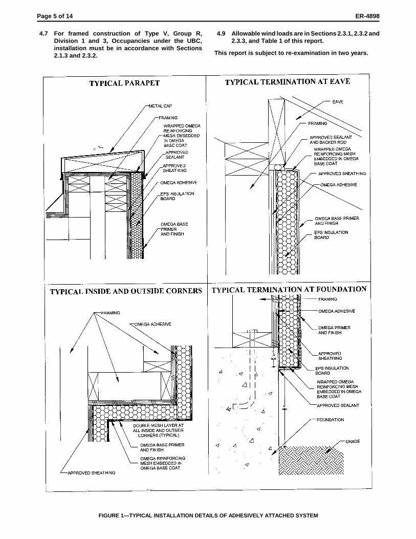
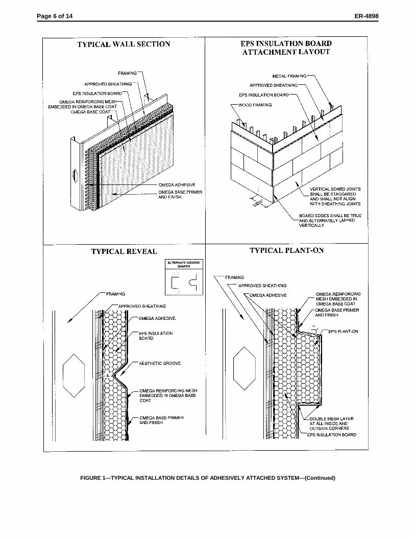
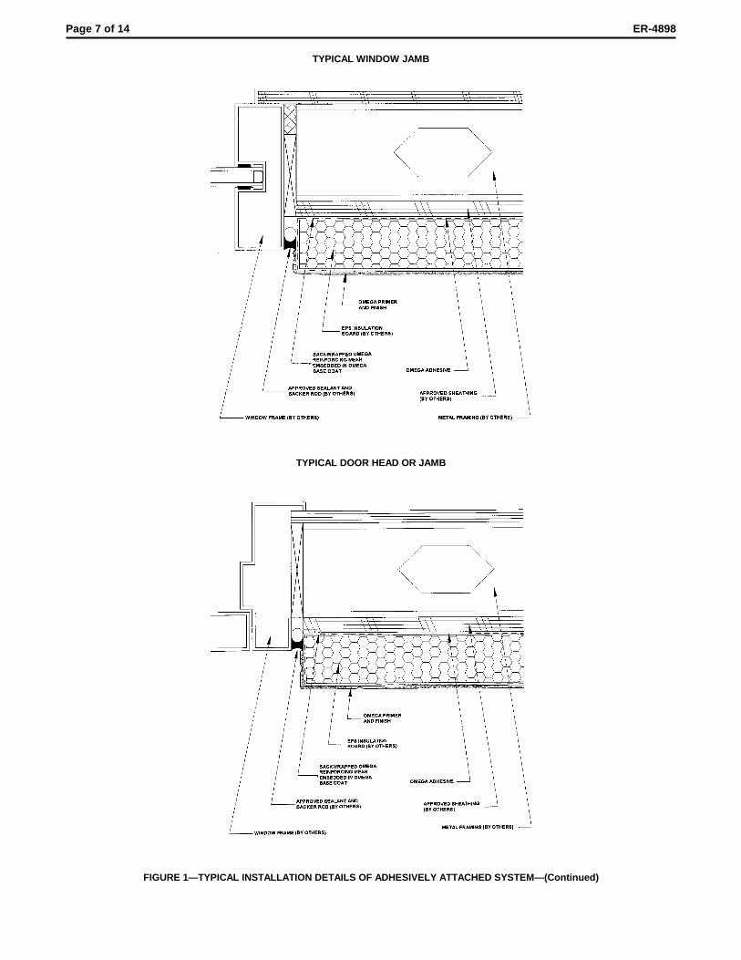
2.3.1.1 General: The substrate must be structurally sound,clean, dry and free of all material that may reduce bonding ofthe adhesive. See Figure 1 for typical installation details.
2.3.1.2 Steel Framing: One-half-inch-thick (12.7 mm) or 5/8-inch-thick (15.9 mm) gypsum sheathing, 1/2-inch-thick Dens-Glass Gold or 5/8-inch-thick (15.9 mm) Dens-Glass GoldFireguard Type X is applied horizontally in accordance withthe applicable code to minimum No. 20 gage [minimum0.0359 inch (0.91 mm) base metal thickness] steel studshaving minimum yield and tensile strengths of 33 and 45 ksi(228 and 310 MPa), respectively. Compass InternationalDarts Brand No. 8 flat, wafer, pancake or modified truss headscrews recognized in evaluation report ER-5202 shall be usedto attach the sheathing to studs at all board edges andintermediate studs. The minimum fastener length is 11/4
inches (32 mm), and the fastener must penetrate the studs atleast 3/8 inch (9.5 mm). Vertical edges of the sheathing mustbutt over studs. When studs are spaced 16 inches (406 mm)on center, 1/2-inch-thick (12.7 mm) gypsum sheathing is usedwith fasteners at 8 inches (203 mm) on center. When studsare spaced 24 inches (610 mm) on center, 5/8-inch-thick (15.9mm) gypsum sheathing is used with fasteners at 6 inches(152 mm) on center. When 1/2-inch-thick (12.7 mm) Dens-Glass Gold board or 5/8-inch-thick (15.9 mm) Dens-Glass GoldFire Stop Type X board is used, studs are spaced 16 or 24inches (406 or 610 mm) on center, respectively, andfasteners are spaced 6 inches (152 mm) on center.

Page 3 of 14 ER-4898
For adhering the EPS to gypsum sheathing or Dens-GlassGold, the adhesive mix of either Styro-Glue or Styro-Glue DryBond is applied to the entire back surface of the EPS boardwith a smooth trowel, and is finished with a 3/8-by-3/8-by-11/2-inch (9.5 by 9.5 by 38 mm), square-notched trowel. Theboard, applied in running bond, is slid into place on thesheathing, and pressure is applied over the entire surface toensure uniform contact. All joints are tightly butted and allboard irregularities exceeding 1/16 inch (1.6 mm) must beeliminated. The adhesive must cure at least 24 hours beforeapplication of the base coat. The base coat is then applied tothe entire exterior surface of the EPS board and is troweledto a uniform thickness of approximately 1/16 inch (1.6 mm),and reinforcing fabric is embedded into the wet base coat.The fabric is troweled from the center to the edges, and mustbe continuous at all corners and lapped at least 2 inches (51mm) at fabric edges.
The base coat must be dry to the touch before proceeding.The drying time required ranges from 4 to 24 hours. When thebase coat is dry, Akroflex primer is sprayed or rolled over theentire surface of the dry base coat. When the primer is dry(usually between 30 and 60 minutes after application), theAkroflex finish is applied directly to the base coat. Minimumthickness of the finish coat is 1/16 inch (1.6 mm).
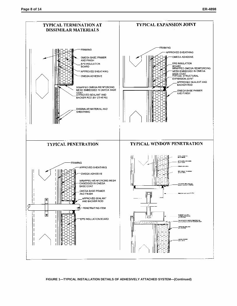
Expansion joints are required at locations where thesubstrate changes, at floor lines in wood-framed constructionin which lumber shrinkage will occur, where the EIFS abutsanother material, and where structural movement isanticipated. Joints must be installed as specified by thearchitect, designer, builder or exterior coating manufacturer,in that order. An approved sealant described in Section 2.2.13must be applied prior to application of the finish coat atsystem terminations, exposed joints, floor lines of wood-framed construction, changes in building shape or roof line,substrate changes, expansion joints and wall penetrations.
The system has an allowable positive and negative windload of 36 psf (1724 Pa) for 16-inch (406 mm) stud spacings,and 31 psf (1484 Pa) for 24-inch (610 mm) stud spacings.Maximum allowable deflection of structural wall componentsis 1/240 of the span. Studs must be designed to resist imposedloads.
2.3.1.3 Wood Studs: Gypsum sheathing or Dens-GlassGold is applied to wood studs spaced 16 inches (406 mm) oncenter, maximum, and mechanically fastened using 6dcommon nails or No. 6 buglehead Type W screws, 11/2 inches(38 mm) long for 1/2-inch-thick (12.7 mm) sheathing and 15/8
inches (41 mm) long for 5/8-inch-thick (15.9 mm) sheathing.The maximum screw fastener spacing is 8 inches (203 mm),except when Dens-Glass Gold board is used, fastenerspacing is 6 inches (152 mm) on center. Vertical board edgesmust butt over studs. The EPS is adhered to the gypsumsheathing or Dens-glass Gold with Styro-Glue or Styro-GlueDry Bond. The balance of the application is as described inSection 2.3.1.2.
For installations over minimum 5/16-inch-thick (7.9 mm)exterior grade plywood or Exposure 1 grade OSB complyingwith the UBC, the plywood and OSB must be attached towood studs spaced a maximum of 16 inches (406 mm) oncenter in accordance with Chapter 23 of the UBC. The EPSmust be adhesively attached to plywood or OSB with Styro-Bond. The adhesive is applied to the entire back surface ofthe insulation board with a trowel having 3/8-inch-wide-by-3/8-inch-deep U-shaped notches spaced 11/2-inches. Before theadhesive has dried, the board is applied to the sheathing withfirm pressure over the entire surface, to ensure uniformcontact. The balance of the application is as described inSection 2.3.1.2.
The allowable positive and negative wind load for thissystem is 36 psf (1724 Pa) when the gypsum sheathing orDens-Glass Gold is screw-fastened, and 26 psf (1245 Pa)when nails are used. Maximum allowable deflection ofstructural wall components is 1/240 of span. Studs must bedesigned to resist the imposed loads.
2.3.1.4 Concrete or Concrete Masonry Substrates: EPSboards are adhered to concrete or concrete masonry surfaceswith Styro-Glue or Styro-Glue Dry Bond adhesives. Theadhesives shall be applied to the insulation board with a 3/8-inch-by-3/8-inch-by-11/2-inch (9.5 mm by 9.5 mm by 38 mm) U-notched trowel. Prior to placement of the insulation on thewall surface, the concrete and concrete masonry must bewetted with a water spray in accordance with themanufacturer’s instructions. The balance of the application isas described in Section 2.3.1.2.
The adhesively adhered system has an allowable windpressure of 32 psf (1532 Pa).
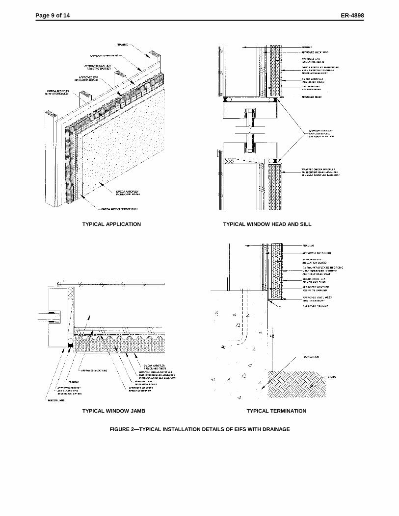
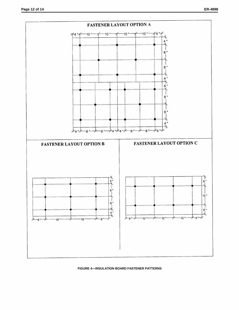
2.3.2 EIFS With Drainage Provisions (MechanicallyAttached Systems): The EIFS with drainage provisions isapplied over wood-based sheathing, gypsum sheathing,Dens-Glass Gold or Durock cement board attached to steelor wood framing. The weather-resistive barrier described inSection 2.2.6 is applied over the substrates. The insulationboard is placed over the weather-resistive barrier andsubstrate, and mechanically fastened as shown in Figure 4.The wood-based sheathings are attached to wood framing inaccordance with Chapter 23 of the UBC, and are attached tosteel framing with corrosion-resistant, No. 8 by 1-inch (25.4mm) self-drilling screws, with 0.292-inch-diameter (7.4 mm)heads, spaced at 6 and 12 inches (152 and 305 mm) at paneledges and intermediate framing members, respectively. Thegypsum sheathing, Dens-Glass Gold and Durock areattached to framing with No. 6 by 1-inch-long, self-drilling,corrosion-resistant screws spaced at 7 inches (178 mm) oncenter at panel edges and in the field of the panel. The EPSis fastened in accordance with the fastening pattern shown inFigure 4. The balance of the application is as described inSection 2.3.1.2. The allowable wind load is shown in Table 1.Studs must be designed to resist the imposed loads. SeeFigure 2 for typical installation details.
2.3.3 EIFS Mechanically Fastened to Concrete/MasonrySubstrates Without Drainage Provisions: The insulationboard is applied horizontally to the substrates in a running-bond pattern and is temporarily attached with two fasteners,placed through washers. Fasteners are corrosion-resistant,minimum 1/4-inch-diameter (6.4 mm) masonry screws with aminimum head diameter of 3/8 inch (9.5 mm), such as Tap-Kwick screws manufactured by Parker-Kalon Division, ABlack & Decker Company (ER-4876). Washers are used withthe screws. All washers must be approved by OmegaProducts Corporation. Two washers that can be utilized arethe plastic Quick-cap washer, supplied by Celotex, or theWind Devil plate, supplied by Wind Lock Corporation, each aminimum of 13/4 inches (44.5 mm) in diameter. Fasteners areinstalled at 12 inches (305 mm) on center vertically, in rows16 inches (406 mm) on center. The balance of the applicationis as described in Section 2.3.1.
Adequacy of fasteners in the substrate is determined by aproof load test program involving fastener withdrawal from thesubstrate in question. Testing must be conducted by anindependent laboratory. Based on a 12-inch-by-16-inch (305mm by 406 mm) spacing and an allowable wind pressure of32 psf (1532 Pa), proof load tests must indicate a minimum256-pound (1139 N) ultimate load for each fastener.
A minimum of five tests per program are required, withresults varying from the average by no more than 15 percent.
Page 4 of 14 ER-4898
If a minimum of 10 tests per program are provided, variationfrom the average may be disregarded. For masonrysubstrates, 40 percent of the tests must be run in masonryjoints.
The applicator must provide the building official with acertificate of compliance concerning test results relating toload requirements in this report. The base coat, reinforcingmesh and finish coat are then applied in a manner similar tothe application described in Section 2.3.1.
2.4 Noncombustible Construction:
2.4.1 General: For application to exterior walls required tobe of noncombustible construction under the UBC, installationshall be in accordance with either Section 2.4.2 or Section2.4.3.
2.4.2 System 1: The wall framing shall be minimum 35/8-inch-deep (92 mm), minimum No. 18 gage [minimum 0.0486inch (1.2 mm) base-metal thickness] steel studs at amaximum of 24 inches (610 mm) on center with No. 20 gage[minimum 0.033 inch (0.84 mm)] tracks. Wall openings areframed with steel having a base metal thickness of 0.0486-inch (1.2 mm). One layer of 5/8-inch-thick (15.9 mm), Type Xgypsum wallboard or 5/8-inch-thick (15.9 mm), Dens-GlassGold Fireguard Type X board is applied horizontally to interiorstud flanges with vertical joints staggered. The wallboard orDens-Glass Gold is fastened to studs, using No. 6, Type S-12, buglehead screws, 13/8 inches (35 mm) long with fastenerspacings as specified in the applicable code for installation ofgypsum wallboard. Water-resistant core, Type X gypsumsheathing, 5/8 inch (15.9 mm) thick, or 5/8-inch- thick (15.9mm) Dens-Glass Gold Fireguard Type X board, is similarlyinstalled to exterior stud flanges. The sheathing on theexterior side is fastened with No. 6, Type S-12, bugleheadscrews, 13/8 inches (35 mm) long, spaced 6 inches (152 mm)on center at edges and 12 inches (305 mm) on center in thefield. Maximum 4-inch-thick (102 mm), 1 pcf density (16kg/m3), EPS board insulation, described in Section 2.2.2.1, isadhered as described in Section 2.3.1. USG Thermafibersafing insulation, 4 pcf (64 kg/m3), having a minimumthickness of 4 inches (102 mm) and recognized in evaluationreport ER-2331, is used to firestop the stud cavities at floorlines. The balance of construction is as described for theadhesively attached system in Section 2.3.1.
2.4.3 System 2: The wall framing shall be minimum 35/8-inch-deep (92 mm), minimum No. 20 gage [minimum 0.0359-inch (0.912 mm) base-metal thickness] steel studs spaced ata maximum of 16 inches on center. Wall openings shall beframed with steel framing with a minimum base metalthickness of 0.0359 inch (0.912 mm). One layer of 1/2-inch-thick (12.7 mm) gypsum wallboard shall be applied verticallyto interior flanges of studs and attached to the wall framingwith 11/4-inch-long (31.7 mm), No. 6, Type S bugleheadscrews spaced at a maximum of 8 inches on center atwallboard joints and 12 inches on center at intermediatelocations. One layer of 1/2-inch-thick (12.7 mm) gypsumsheathing shall be applied horizontally to exterior flanges ofstuds and attached to the wall framing with 11/4-inch-long(31.7 mm), No. 6, Type S buglehead screws spaced at amaximum of 8 inches on center. The wallboard joints must bestaggered from the gypsum sheathing joints. USGThermafiber 4 pcf (64 kg/m3) safing insulation having aminimum thickness of 4 inches (102 mm), and recognized inevaluation report ER-2331, shall be used to firestop the studcavities at floor lines. Maxmium 4-inch thick (102 mm), 1 pcfdensity (16 kg/m3) EPS insulation board, described in Section2.2.2.1, is adhered to the gypsum sheathing with Styro-GlueDry Bond in accordance with Section 2.3.1.2. The reinforcingmesh is embedded into a base coat of Styro-Glue Dry Bond
applied as described in Section 2.3.1.2. The finish coat isapplied to the base coat as described in Section 2.3.1.2.
2.5 Identification:
Containers of adhesives, base coats and finish coats of theOmega Akroflex System bear a label noting the name of theproduct; the Omega Products International, Inc., name andaddress; the evaluation report number (ER-4898); theproduction date; the batch number; quantity of material;storage, mixing and curing instructions; and expiration date.
The foam plastic insulation boards must be labeled inaccordance with their respective ICC-ES evaluation reports.Additionally, the board density must be noted. When thesystem is applied to walls required to be noncombustibleconstruction, the name “Akroflex” and the evaluation reportnumber (ER-4898) must also be along one edge of eachboard, and on both faces of one board in each package.
Cartons of JPS Glass reinforcing fabric are identified withthe manufacturer’s name, product name and model numberof the fabric.
Cartons of Quick-cap washers and Wind Devil, Wind-Devil2 and Plasti-Grip plates and screws are identified with themanufacturer’s name, product name, quantity and installationinstructions.
Containers of the weep screed starter track are identifiedwith the manufacturer’s name and product name.
3.0 EVIDENCE SUBMITTED
Data in accordance with the ICC-ES Interim Criteria forExterior Insulation and Finish Systems (AC24), dated June2003, and a quality control manual.
4.0 FINDINGS
That the Omega Akroflex Exterior Insulation and FinishSystems described in this report comply with the 1997Uniform Building Code™ (UBC), subject to the followingconditions:
4.1 Construction is as set forth in this report and themanufacturer’s instructions.
4.2 Foam plastic insulation board is separated from thebuilding interior by a thermal barrier complying withUBC Section 2602, such as minimum 1/2-inch (12.7mm) gypsum wallboard mechanically attached inaccordance with the UBC, or a minimum 1-inch (25mm) thickness of concrete or masonry.
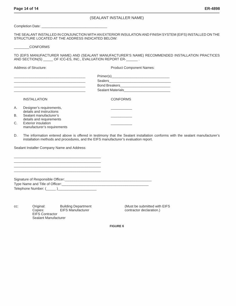
4.3 Installation is by applicators approved by OmegaProducts International, Inc. Installation cards, suchas those shown in Figures 5 and 6, must becompleted by the applicator and presented to thebuilding official at the completion of each project.
4.4 Insulation boards are labeled in accordance withthis report.
4.5 The Akroflex system may be installed over thesurface of exterior, fire-resistance-rated,combustible wall assemblies as described in UBCTable 7-B without changing the assigned hourlyrating of the assembly.
4.6 The system may be installed on exterior wallsrequired to be of noncombustible, non-fire-resistive,construction under the UBC, provided installation isin accordance with Section 2.4 of this report.
Page 5 of 14 ER-4898
4.7 For framed construction of Type V, Group R,Division 1 and 3, Occupancies under the UBC,installation must be in accordance with Sections2.1.3 and 2.3.2.
4.9 Allowable wind loads are in Sections 2.3.1, 2.3.2 and2.3.3, and Table 1 of this report.
This report is subject to re-examination in two years.
FIGURE 1—TYPICAL INSTALLATION DETAILS OF ADHESIVELY ATTACHED SYSTEM
Page 6 of 14 ER-4898
FIGURE 1—TYPICAL INSTALLATION DETAILS OF ADHESIVELY ATTACHED SYSTEM—(Continued)
Page 7 of 14 ER-4898
TYPICAL WINDOW JAMB
TYPICAL DOOR HEAD OR JAMB
FIGURE 1—TYPICAL INSTALLATION DETAILS OF ADHESIVELY ATTACHED SYSTEM—(Continued)
Page 8 of 14 ER-4898
FIGURE 1—TYPICAL INSTALLATION DETAILS OF ADHESIVELY ATTACHED SYSTEM—(Continued)
Page 9 of 14 ER-4898
TYPICAL APPLICATION TYPICAL WINDOW HEAD AND SILL
TYPICAL WINDOW JAMB TYPICAL TERMINATION
FIGURE 2—TYPICAL INSTALLATION DETAILS OF EIFS WITH DRAINAGE
Page 10 of 14 ER-4898
TYPICAL EXPANSION JOINT TYPICAL CONTROL JOINT AT DISSIMILAR MATERIALS
TYPICAL MESH LAYOUT THROUGH PENETRATION
FIGURE 2—TYPICAL INSTALLATION DETAILS OF EIFS WITH DRAINAGE—(Continued)
Page 11 of 14 ER-4898
FIGURE 3—CORRUGATED EPS
Page 12 of 14 ER-4898
FIGURE 4—INSULATION BOARD FASTENER PATTERNS

Page 13 of 14 ER-4898
(EIFS CONTRACTOR NAME)
Completion Date:______________________________________
THE EXTERIOR INSULATION AND FINISH SYSTEM (EIFS) INSTALLED ON THE STRUCTURE LOCATED AT THE ADDRESSINDICATED BELOW:
________ CONFORMS
TO OMEGA PRODUCTS INTERNATIONAL, INC., RECOMMENDED INSTALLATION PRACTICES AND SECTION (S) _______OFICC-ES, INC., EVALUATION REPORT ER-4898.
Address of Structure: Product Component Names:
___________________________________ Adhesive(s)________________________________________________________________ Fasteners (mech)____________________________________________________________ Base Coat__________________________________________________________________ Reinforcing Fabric________________________
Finish Coat (s)___________________________
INSTALLATION CONFORMS
A. Substrate Type and Tolerance ___________
B. Weather Resistive Barrier ___________(Type V Construction Only)
C. EIFS1. Adhesive and/or Fasteners ___________2. Insulation ___________3. Reinforcing Fabric ___________4. Base Coat ___________5. Finish ___________
D. The information entered above is offered in testimony that the EIFS installation conforms with the EIFS manufacturer’s installationmethods and procedures, and the EIFS manufacturer’s ES report.
NOTE: An installation card shall be received from the Sealant Installer indicating that the sealant installation conforms with the EIFSevaluation report and sealant manufacturer’s installation methods and procedures must accompany this declaration.
EIFS Contractor Company Name and Address:
____________________________________________________________________________________________________________________________________________________________________________________________________________________________
Signature of Responsible Officer:___________________________________________Type Name and Title of Officer:___________________________________________Telephone Number: (_____ )__________________________
cc: Original: Building Department (Must be submitted with sealantCopy: Omega Products International, Inc. installer declaration.)
FIGURE 5
Page 14 of 14 ER-4898
(SEALANT INSTALLER NAME)
Completion Date: __________________________________
THE SEALANT INSTALLED IN CONJUNCTION WITH AN EXTERIOR INSULATION AND FINISH SYSTEM (EIFS) INSTALLED ON THESTRUCTURE LOCATED AT THE ADDRESS INDICATED BELOW:
________CONFORMS
TO (EIFS MANUFACTURER NAME) AND (SEALANT MANUFACTURER’S NAME) RECOMMENDED INSTALLATION PRACTICESAND SECTION(S) _____ OF ICC-ES, INC., EVALUATION REPORT ER-______ .
Address of Structure: Product Component Names:
_____________________________________ Primer(s)___________________________________________________________________ Sealers_____________________________________________________________________ Bond Breakers_______________________________________________________________ Sealant Materials________________________
INSTALLATION CONFORMS
A. Designer’s requirements, ___________details and instructions
B. Sealant manufacturer’s ___________details and requirements
C. Exterior insulation ___________manufacturer’s requirements
D. The information entered above is offered in testimony that the Sealant installation conforms with the sealant manufacturer’sinstallation methods and procedures, and the EIFS manufacturer’s evaluation report.
Sealant Installer Company Name and Address:
____________________________________________________________________________________________________________________________________________________________________________________
Signature of Responsible Officer:_____________________________________________Type Name and Title of Officer:_____________________________________________Telephone Number: (_____ )____________________
cc: Original: Building Department (Must be submitted with EIFSCopies: EIFS Manufacturer contractor declaration.)EIFS ContractorSealant Manufacturer
FIGURE 6