Embed Size (px)
DESCRIPTION
1
Citation preview

Lesson 10Valves
Objective In this section we will answer the following questions:
· What are the four basic valve designs?
· What is a valve? What are their purposes?
· What are the different types of valves?
· How does one determine the correct valve size?
Reading Assignment Read the online lecture as well as the supplemental material found at the following links:
Check ValvesChoosing the Right Valve
Valve Sealing
Introduction to Valves
The following information includes the four basic designs from which valves are developed. The uses of basic materials from which valves are made -
such as bronze, cast iron, steel and PVC - are illustrated. Also, the basic uses for which valves are usually installed are explained.
It is well to know and understand some of the common abbreviations in the valve industry, such as:
S.P. - Steam Pressure W.P. - Working Pressure
W.O.G.- Water, Oil, Gas Pressure
B.R. - Bronze I.B.B.M. - Iron Body Bronze Mounted
A.I. - All Iron
C.S. - Cast Steel S.S. - Stainless Steel
PVC - Polyvinyl Chloride
O.S. & Y.- Outside Screw and Yoke
N.R.S. - Non-Rising Stem R.S.- Rising Stem
Definition of a Valve
A Valve is a mechanical device used in connection with a pressure containing vessel to stop completely or regulate flow.
For the purpose of simplicity, this definition may be further condensed into the following: A Valve is a mechanical device used to regulate flow.
As a mechanical device it should be treated as any other mechanical device. It should be properly installed and used. It will wear under usage or
misusage. It may have to be repaired or replaced. If it is not used frequently, it may become frozen or hard to operate.
The function of a valve is to regulate flow.
A Gate Valve is usually used to stop flow completely. A Globe Valve is used to regulate or throttle flow. Just to be able to tell where you shoulduse a gate valve or a globe valve is important. A Check Valve is used to prevent back flow.

Valves are usually connected to pipe or to pressure containing vessels by a screwed connection, or a flanged joint. There are other types ofconnections, such as butt-welding ends, socket-welding ends, grooved ends for coupling, solder ends, etc.
Pressure Containing Vessels In order to establish flow, it is necessary to have a primary source of pressure. The four sources of pressure listed below are the most commonly
encountered in general use. These four sources are:
1. A boiler for steam 2. An air compressor and tank for compressed air.
3. Natural pressures underground, such as oil wells. 4. Head pressure, such as a tank for water or pump.
Each of the liquids or gases mentioned require careful consideration of the design and material in a valve to give the best results for that particularservice.
It is interesting to note that valves are usually classified by their Steam Pressure (S.P.) rating. The Water, Oil, Gas (W.O.G.) ratings usually follow.
These two ratings are directly related to the four types of pressure-containing vessels noted above.
Methods to Keep Pressure in the Vessel
For the purpose of this discussion let us assume a hollow sphere with an opening in it as representing the pressure-containing vessel. The sphere isassumed to be under 10 lbs internal pressure. It is desired to regulate or stop completely the flow of the fluid from this pressure-containing vessel. The following methods can be used.

Diagram "A". When the covering is on the outside of the vessel, the basic principle of the globe valve is used. Here we have a metal tometal joint, and the covering can be held by a clamp. In a valve this method appears in the metal disc globe valves which are of the regrindingor renewable seat type.
Diagram "B". In this diagram we have a gasket under the metal cover, and this cover is again held to the opening by a clamp. In valves,this method appears in "N-M-D" globe valves, sometimes called composition disc, or soft disc globe valves.
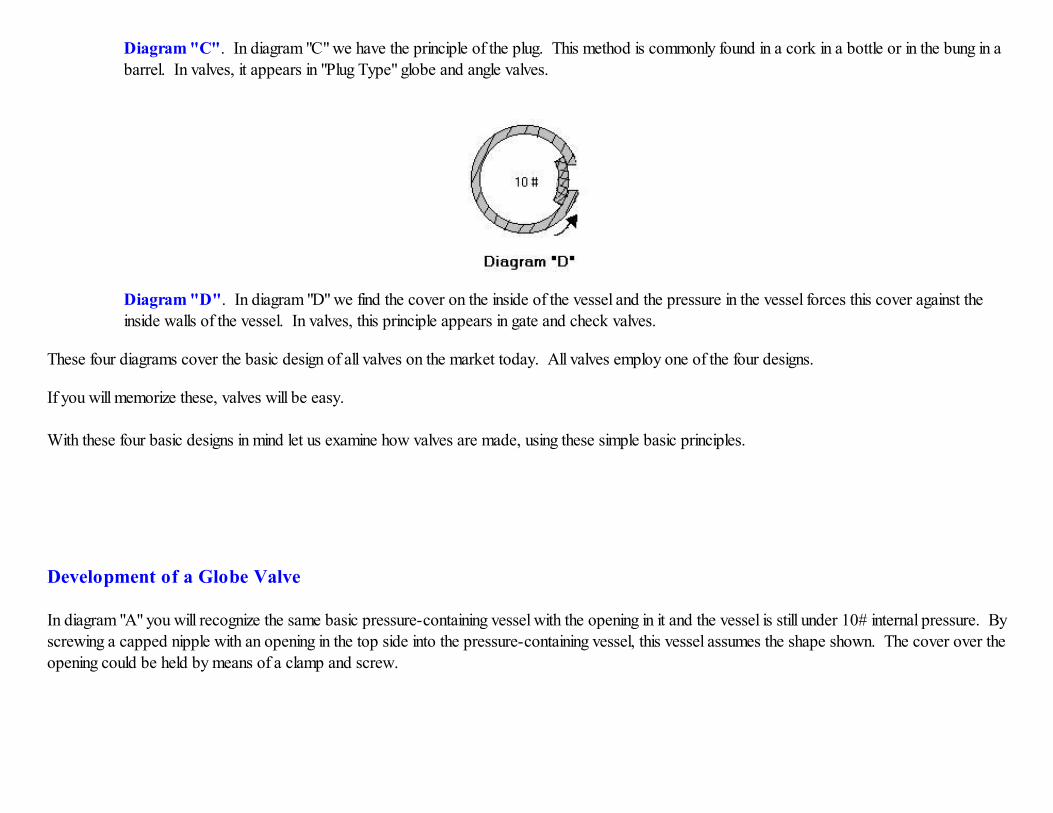
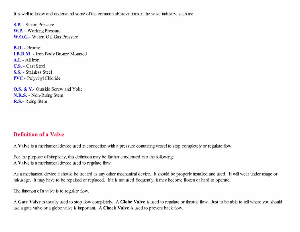
Diagram "C". In diagram "C" we have the principle of the plug. This method is commonly found in a cork in a bottle or in the bung in abarrel. In valves, it appears in "Plug Type" globe and angle valves.
Diagram "D". In diagram "D" we find the cover on the inside of the vessel and the pressure in the vessel forces this cover against theinside walls of the vessel. In valves, this principle appears in gate and check valves.
These four diagrams cover the basic design of all valves on the market today. All valves employ one of the four designs.
If you will memorize these, valves will be easy.
With these four basic designs in mind let us examine how valves are made, using these simple basic principles.
Development of a Globe Valve
In diagram "A" you will recognize the same basic pressure-containing vessel with the opening in it and the vessel is still under 10# internal pressure. Byscrewing a capped nipple with an opening in the top side into the pressure-containing vessel, this vessel assumes the shape shown. The cover over theopening could be held by means of a clamp and screw.

Diagram "A"
In diagram "B", we find by connecting a globe valve to the pressure-containing vessel, the valve becomes part of that vessel. Into the globe valve hasbeen built the opening - called the seat - and the covering - called the disc, and the mechanical device for opening or closing the covering - called thestem and bonnet.
Globe valves are usually used where it is desired to throttle or regulate the flow of a fluid. They are also specified to be used where the valve is to beopened and closed frequently.
Development of a Gate Valve
In diagram "A", we find the pressure-containing vessel taking the form shown, with a flat surface and the covering over the opening on the inside. The
10# internal pressure is forcing the disc or covering against the side walls of the vessel.
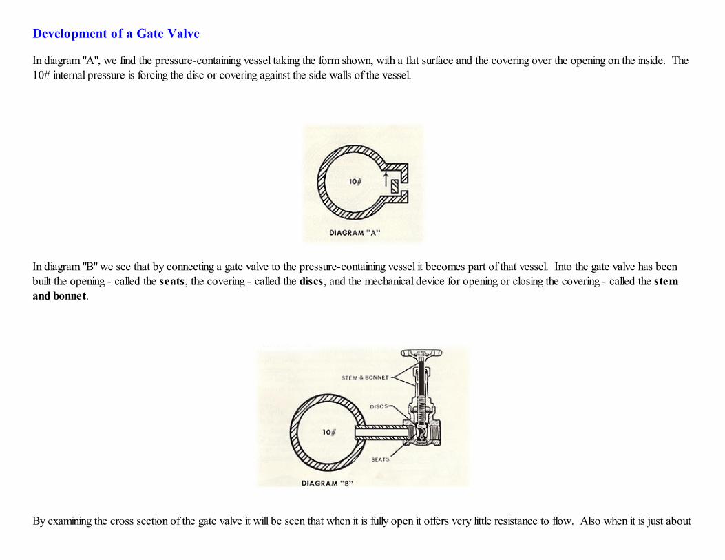
In diagram "B" we see that by connecting a gate valve to the pressure-containing vessel it becomes part of that vessel. Into the gate valve has beenbuilt the opening - called the seats, the covering - called the discs, and the mechanical device for opening or closing the covering - called the stemand bonnet.
By examining the cross section of the gate valve it will be seen that when it is fully open it offers very little resistance to flow. Also when it is just about

fully closed, all the throttling is done on the bottom of the discs and seats, making for uneven wear by erosion.
For these two reasons gate valves are recommended for use when they are either fully open or closed. They offer little resistance when open and arenot suited for throttling purposes when almost fully closed.
Also note that the internal pressure always forces the down stream disc against its seat. For this reason gate valves only wear on the down streamside. This wear is eliminated by carefully guiding the disc to its seat. The wear is taken up by guides built into the body of the valve which accuratelyengage machined wings on the discs.
Development of Check Valves
In diagrams "A" and "B", we find the pressure-containing vessel takes the same form as for a gate valve, with a flat surface, and with the covering overthe opening on the outside. In diagram "A" we have the elements of a swing check valve and in diagram "B" we have the elements of a lift check valve.
Diagram "A"
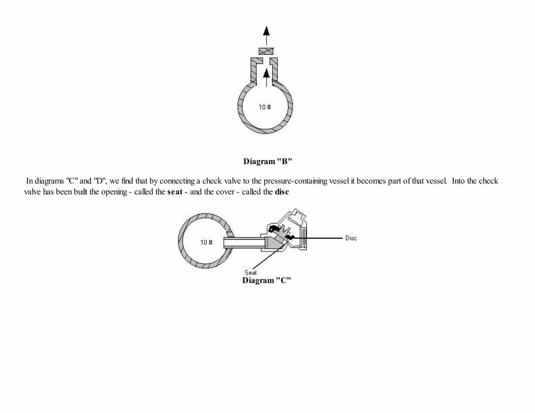
Diagram "B"
In diagrams "C" and "D", we find that by connecting a check valve to the pressure-containing vessel it becomes part of that vessel. Into the check
valve has been built the opening - called the seat - and the cover - called the disc
Diagram "C"
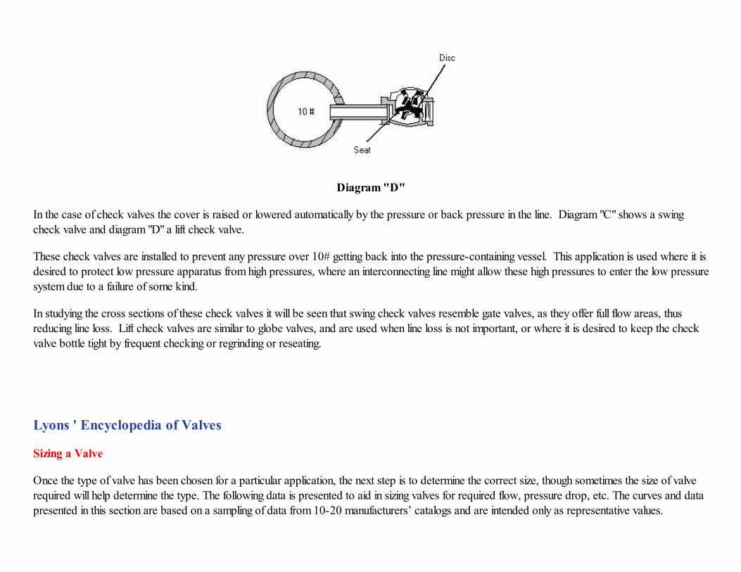
Diagram "D"
In the case of check valves the cover is raised or lowered automatically by the pressure or back pressure in the line. Diagram "C" shows a swingcheck valve and diagram "D" a lift check valve.
These check valves are installed to prevent any pressure over 10# getting back into the pressure-containing vessel. This application is used where it isdesired to protect low pressure apparatus from high pressures, where an interconnecting line might allow these high pressures to enter the low pressure
system due to a failure of some kind.
In studying the cross sections of these check valves it will be seen that swing check valves resemble gate valves, as they offer full flow areas, thusreducing line loss. Lift check valves are similar to globe valves, and are used when line loss is not important, or where it is desired to keep the check
valve bottle tight by frequent checking or regrinding or reseating.
Lyons ' Encyclopedia of Valves
Sizing a Valve
Once the type of valve has been chosen for a particular application, the next step is to determine the correct size, though sometimes the size of valverequired will help determine the type. The following data is presented to aid in sizing valves for required flow, pressure drop, etc. The curves and data
presented in this section are based on a sampling of data from 10-20 manufacturers’ catalogs and are intended only as representative values.
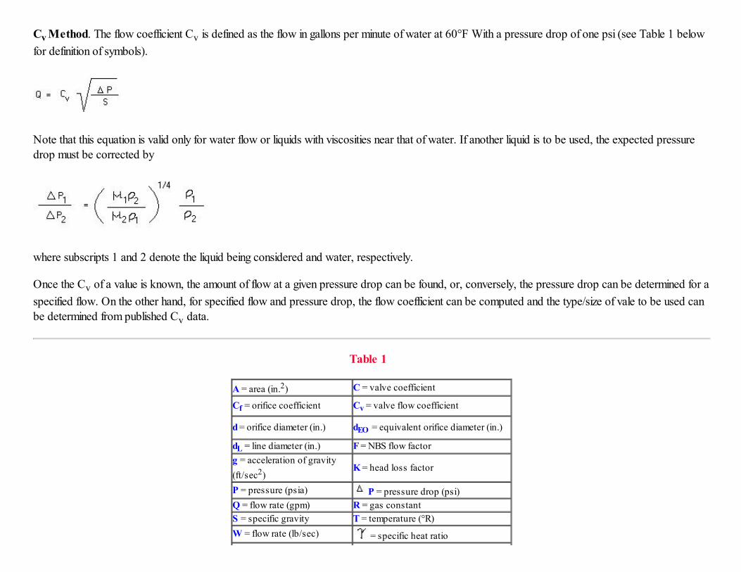
Cv Method. The flow coefficient Cv is defined as the flow in gallons per minute of water at 60°F With a pressure drop of one psi (see Table 1 below
for definition of symbols).
Note that this equation is valid only for water flow or liquids with viscosities near that of water. If another liquid is to be used, the expected pressuredrop must be corrected by
where subscripts 1 and 2 denote the liquid being considered and water, respectively.
Once the Cv of a value is known, the amount of flow at a given pressure drop can be found, or, conversely, the pressure drop can be determined for a
specified flow. On the other hand, for specified flow and pressure drop, the flow coefficient can be computed and the type/size of vale to be used can
be determined from published Cv data.
Table 1
A = area (in.2) C = valve coefficient
Cf = orifice coefficient Cv = valve flow coefficient
d = orifice diameter (in.) dEO = equivalent orifice diameter (in.)
dL = line diameter (in.) F = NBS flow factor
g = acceleration of gravity
(ft/sec2) K = head loss factor
P = pressure (psia) P = pressure drop (psi)
Q = flow rate (gpm) R = gas constant
S = specific gravity T = temperature (°R)
W = flow rate (lb/sec) = specific heat ratio
= absolute viscosity(centipoise)
v = kinematic viscosity (centistoke)
= Pi (3.1415926...) = density (lb/ft3)
Subscript 1 = value for otherliquid
Subscript 2 = value for water
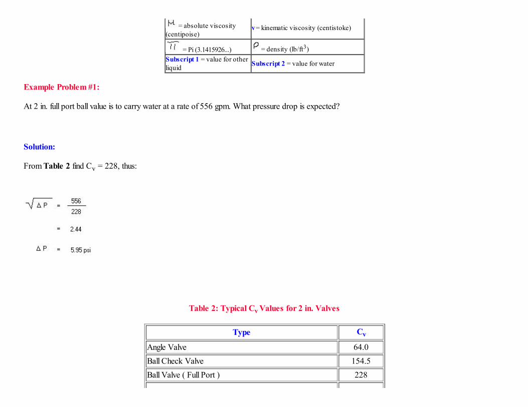
Example Problem #1:
At 2 in. full port ball value is to carry water at a rate of 556 gpm. What pressure drop is expected?
Solution:
From Table 2 find Cv = 228, thus:
Table 2: Typical Cv Values for 2 in. Valves
Type Cv
Angle Valve 64.0
Ball Check Valve 154.5
Ball Valve ( Full Port ) 228

Ball Valve ( Standard Port ) 120
Butterfly Valve 145
Coaxial Valve 154.5
Cone Poppet Check Valve 166
Flat Poppet Check Valve 133
Gate Valve 210
Globe Valve 44.34
Pinch Valve 181
Plug, Taper Valve 70
Swing Check Valve 138.2
Y-Valve
45° Angle 72.0
60° Angle 70.8
Example Problem #2:
A 2 in. globe valve is allowed a pressure drop of 64 psi when carrying water. How many gallons/minute of oil (specific gravity 0.8, kinematic viscosity0.82) will it pass and what is the expected pressure drop? The kinematic viscosity of water is 0.93.
Solution:
From Table 2 find Cv = 44.34, thus:
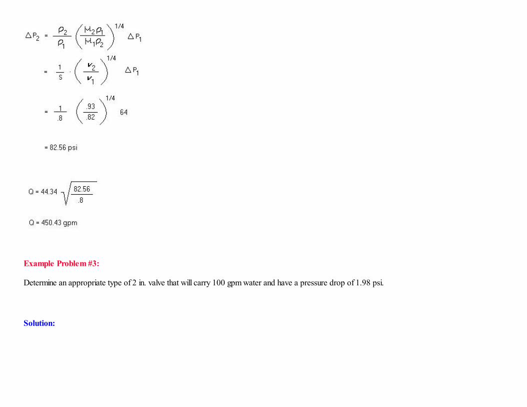
Example Problem #3:
Determine an appropriate type of 2 in. valve that will carry 100 gpm water and have a pressure drop of 1.98 psi.
Solution:
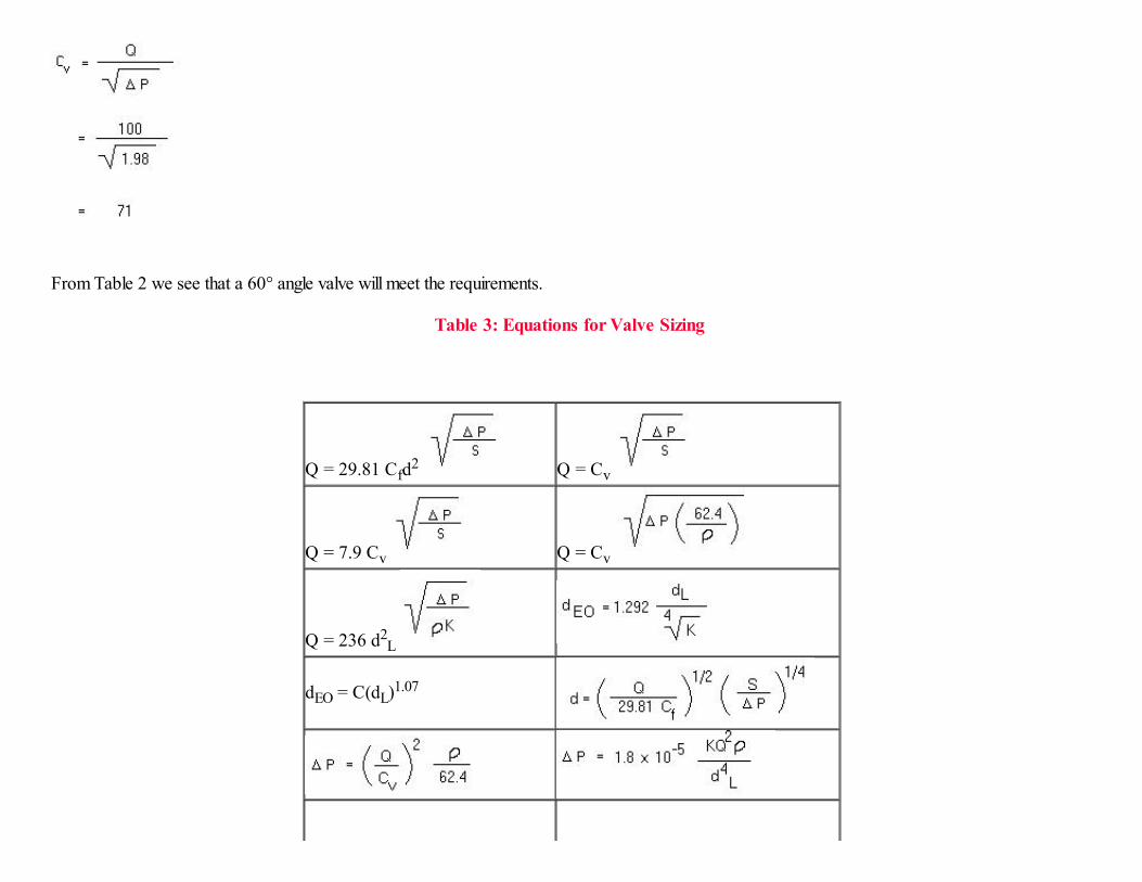
From Table 2 we see that a 60° angle valve will meet the requirements.
Table 3: Equations for Valve Sizing
Q = 29.81 Cfd2 Q = Cv
Q = 7.9 Cv Q = Cv
Q = 236 d2L
dEO = C(dL)1.07

Equivalent Orifice Method
Since the flow through a sharp edge orifice can be conveniently calculated with good accuracy, it would be desirable to relate flow through a valve tothat through a sharp edge orifice. This can be done to high accuracy with the use of the equivalent orifice method.
This procedure consists of three basic steps. The first step is to compute the sharp edge orifice diameter. This can be found from one of the followingequations (See Table 3 for alternate forms of equations).
for liquids,
for gases under sonic flow conditions, or
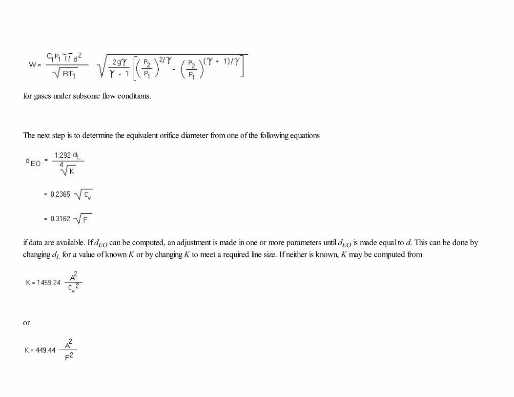
for gases under subsonic flow conditions.
The next step is to determine the equivalent orifice diameter from one of the following equations
if data are available. If dEO can be computed, an adjustment is made in one or more parameters until dEO is made equal to d. This can be done by
changing dL for a value of known K or by changing K to meet a required line size. If neither is known, K may be computed from
or

and the line size chosen to meet this K-factor. Alternatively, a new valve and K-factor may be chosen to fit a line size.
If dEO cannot be computed from known information, a trial and error procedure can be used. Set dEO equal to d and use Figs. 1 and 3 (yet to come)
to choose a valve. From its coefficient C and dEO find the proper line diameter, or conversely, from a required line diameter find the valve type from
the coefficient C. Once the valve coefficient and line diameter are known, the K-factor for the valve may be found from Fig. 2.
In summary, to fully size a valve for a given flow and pressure drop, determine the coefficient C, the K-factor of the valve, and its line diameter. Notethat one two, but not all of these may be specified beforehand. All three, however, may be specified if the flow and/or pressure drop are not specified.The following problems will illustrate the procedure.
Example Problem #4:
a 1 1/2 in. full port ball valve has a valve flow coefficient C of 1.7. What is the number of gallons per minute of water it will pass with a pressure drop
of 1.2 psi?
Solution:
From Fig. 1, find C = 1.70. Then from Fig. 3 find dEO = 2.62 in. Hence
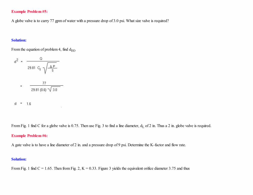
Example Problem #5:
A globe valve is to carry 77 gpm of water with a pressure drop of 3.0 psi. What size valve is required?
Solution:
From the equation of problem 4, find dEO
From Fig. 1 find C for a globe valve is 0.75. Then use Fig. 3 to find a line diameter, dL of 2 in. Thus a 2 in. globe valve is required.
Example Problem #6:
A gate valve is to have a line diameter of 2 in. and a pressure drop of 9 psi. Determine the K-factor and flow rate.
Solution:
From Fig. 1 find C = 1.65. Then from Fig. 2, K = 0.33. Figure 3 yields the equivalent orifice diameter 3.75 and thus

(Note: This information is courtesy of Lyons ' Encyclopedia of Valves. Jerry L. Lyons P.E. and Carl L. Askland, Jr. Van Nostrand Reinhold Company. New York /Cincinnati / Toronto / London / Melbourne )
Lyons ' Encyclopedia of Valves
Design Factors
In this section we consider some of the important factors pertaining to the design of a valve for a specified service. In many applications there are
several types of valves that will function equally well and the choice may be based solely on such things as cost, availability, etc. For other applicationsit may be that no off-the-shelf valve is available and a custom design may be necessary. The proper choice or design may be made easier by properattention to the factors discussed below.
Factors Related to Usage
In many cases only one or two of the basic valve types are suitable for a specified use because of the design of the valve. Under other conditions,several types of valves are suitable and other factors such as materials may be of prime importance.
o Contamination. For control of fluids which may cause contamination buildup, a valve with minimum obstruction to flow is
needed. Ball, gate, globe and pinch valves are suitable for this purpose.o Directional Control. For control of the direction of fluid flow, a check valve which blocks flow in one direction and allows full
flow in the other, or a restrictor valve which allows only a specified flow in one or more directions, is required. Poppet and
swing valves are widely used for this function.

o High Pressure. The control of high pressure flow generally calls for a ball or globe valve although gate and poppet valves areoccasionally used. The selection of a valve to be used in a high pressure application, particularly pneumatic, should beapproached with extreme caution. The design of such valves should be left to qualified engineers.
o High Temperature. In most situations the same considerations that apply to high pressure valves apply to high temperaturevalves. In addition, care must be taken to ensure that thermal expansion does not cause binding or deformation in the valve.
o Low Leakage. All of the basic valves can be made leaktight, but often with high cost and complexity. Generally, for tightshutoff one should consider ball, gate, globe and plug valves.
o Relief and Safety. For rapid opening response to overpressure and large flow to vent, one should nearly always consider aspring loaded poppet valve. The other types of valves are not normally considered for these functions
o Shutoff. For normal on-off control the best choices are ball, gate, globe and plug valves. The ball and plug vales normally open
faster than gate or globe valves.o Steam Service. The control of steam under pressure generally calls for a ball or globe valve.o Throttling. To control the amount of flow by varying the amount of opening, a globe valve is usually recommended. In contrast
to most ball and gate valves, it does not tend to vibrate under flow.
Factors Related to Construction
Actuator. The means of operating the valve will depend on the type of valve, its location and function in a system, size of the valve, frequency ofoperation, and degree of control desired. Some common means of actuation are hand, gear, chainwheel, lever, spring, motor, solenoid, servo, gravity,and pressure and flow rate of the fluid media. Generally, a particular type of valve is limited to one of a few types of actuators, for example, relief and
safety valves are spring actuated, check valves are spring or gravity actuated, and high pressure globe valves are usually actuated by chainwheels,motors, etc. Automatic process control calls for servo-valves, solenoid and spring actuators.
Ball Butterfly Gate Globe Pinch Plug Poppet Swing
Check Valve P P P P P P G G
Contamination Free G F G G G G F P
Corrosive Fluids G P F-G F F-G P-F G G

Cryogenic Fluids G P P G P P G P
Gases G G G G G G G G
High P P F G P F F P
High Flow G G G G G G G G
High Pressure G P P G P P G P
High Temperature G G G G P P-G G G
Leaktight G P G G G G G P
Lightweight G G F P F G G G
Liquids G G G G G G G G
Low Actuation Force P P P P P P G G
Low Cost G F-G G F-G G G G G
Low G G G P G G G G
Low Flow Control G G P G F G G G
Rapid Opening G G P F-P P G G G
Relief P P P P P P G P
Safety Valve P P P P P P G P
Seat Erosion Resistance F P P G P F F-G P
Slurries F-G P P P G P P P
Small Physical Size G G P P P G G G
Steam Service G P P-F G P P G P
Throttling P P P G F-P P G P
Vibration Free F P P G G G P P
P = Poor, Not Recommended
F = Fair, Better Choices Available G = Good, Recommend For Use Under Normal Conditions
Closure Member. The type of closure member desired or required will normally determine the type of valve to be used. Conversely, the choice of avalve type will usually determine the type of closure member. The common closure members are the ball, disc, gate, plug and poppet.
End Fittings. The type of end fittings to be specified for a valve is normally determined by the nature of the piping system into which it must beinserted. Some common fittings are brazing end, butt weld ends, compression, flange, flared, hose ends, hub ends, pipe thread, quick disconnect,socket and solder ends. For high pressure and/or high temperature conditions, one of the various types of flange ends or a threaded fitting should be

considered.
Material. The material selected for valve trim will depend on the nature of the fluid to be carried, the operating pressure and temperature, the type ofclosure member and seat, and factors such as cost, weight, etc. Control of corrosive liquids and gases calls for stainless steels, nickel alloys, variousplastics, and ceramic materials. For high pressure service and/or high temperatures consider various steels, nickel alloys, titanium alloys and similar high
strength materials. For steam service consider cast iron steel, bronze and similar metals. Nuclear valves call for special steels, titanium and other alloysdeveloped especially for this type of service. In all cases of severe use conditions, manufacturers literature should be consulted to determine thesuitability of a particular valve.
Packing/Seals. In most valves consideration must be given to possible leakage around the stem or actuator. In common valves a packing material isprovided as a seal. However, this tends to wear out with use. If replacement is undesirable or unfeasible, consideration should be given to bellows sealvalves, diaphragm seals, etc.
Seat. There are many styles of valve seats available in most of the types of valves discussed. They may differ in geometry, material, rigidity, etc.
Conical valve seats can provide a wide sealing surface which minimizes eroding or "wire drawing" of the surface. A conical seat may also be designedwith a narrow sealing surface to provide very tight sealing at low pressures. Spherical or ball seats have much the same characteristics as the conicalseat. However, they are more costly to produce. Flat seats are used in valves that need not be leaktight since they generally do not seal completely at
low pressures. (Note: This information is courtesy of Lyons ' Encyclopedia of Valves. Jerry L. Lyons P.E. and Carl L. Askland, Jr. Van Nostrand Reinhold Company. New York /Cincinnati / Toronto / London / Melbourne ).
Assignment
Answer the following questions and either mail or fax to the instructor.
1. What is the definition of a valve?2. What are the four sources of pressure in order to establish flow?

3. What is the next step after you have chosen the type of valve for a particular application?4. What type of valve is used for rapid opening response to over pressure and large flow to vent?5. What type of seat has the same characteristic as the conical seat?
Quiz
Answer the questions in Quiz 10. When you have completed the quiz, print it out and either mail or fax to the instructor. You may also take the quizonline and directly subit it into the database for a grade.