Embed Size (px)
Citation preview
Level Plus®
Liquid-Level Sensors With Temposonics® Technology
M-Series Model MRAnalog Transmitter
SENSORS
®
Document Part Number550720 Revision G
Operation and Installation Manual

Cont
act
Info
rmat
ion
Model MR Operation and Installation ManualContact Information
MTS SensorsLevel Plus® Liquid-Level Sensors M-Series Model MR Analog Transmitter
Operation and Installation Manual, Document Number 550720 Revision G 09/11
GeRMaNy
GeNeRal:
Tel.: +49-2351-9587-0Fax: +49-2351-56491e-mail: [email protected]://www.mtssensor.de
MaIlING aND ShIPPING aDDReSS:
MTS Sensor Technologie, GmbH & Co. KGAuf dem Schüffel 9D - 58513 Lüdenscheid, Germany
TechNIcal SuPPORT aND aPPlIcaTIONS:
Tel.: +49-2351-9587-0e-mail: [email protected]://www.mtssensor.de
JaPaN
GeNeRal:
Tel.: +81-42-775-3838Fax: +81-42-775-5516 e-mail: [email protected]://www.mtssensor.co.jp
MaIlING aND ShIPPING aDDReSS:
MTS Sensors Technology Corporation737 Aihara-cho, Machida-shiTokyo 194-0211, Japan
TechNIcal SuPPORT aND aPPlIcaTIONS:
Tel.: +81-42-775-3838Fax: +81-42-775-5512
GeNeRal:
Tel: +1-919-677-0100Fax: +1-919-677-2343E-mail: [email protected]://www.mtssensors.com
MaIlING aND ShIPPING aDDReSS:
MTS Systems CorporationSensors Division3001 Sheldon DriveCary, North Carolina, 27513, USA
cuSTOMeR SeRvIce:
Tel: +1-800-457-6620Fax: +1-800-498-4442E-mail: [email protected]
TechNIcal SuPPORT aND aPPlIcaTIONS:
24 Hour Emergency Technical SupportTel: +1-800-633-7609e-mail: [email protected]
uNITeD STaTeS
OffIce hOuRS (eST):
Monday - Thursday: 8:00 a.m. to 5:00 p.m.Friday: 8:00 a.m. to 4:00 p.m.
ReMITTaNce aDDReSS:
MTS Systems CorporationSensors DivisionNW 5872 P.O. Box 1450Minneapolis, MN, 55486-5872
QuOTe aND cONTRacT TeRMS & cONDITIONS:
The parties expressly agree that the purchase and use of Material and/or Services from MTS Sensors Division are subject to MTS’ Terms and Conditions, in effect as of the date of this document, which are located at http://www.mtssensors.com/fileadmin/media/pdfs/Terms_and_conditions.pdf and are incorporated by reference into this and any ensuing contract. Printed Terms and Conditions can be provided upon request by emailing [email protected] or if you prefer, go to http://www.mtssensors.com/index and click the Quote/Contract Terms and Conditions link at the bottom of the page to download the PDF.
i
Refe
renc
e In
form
atio
n
MTS SensorsLevel Plus® Liquid-Level Sensors M-Series Model MR Analog Transmitter Operation and Installation Manual, Document Number 550720 Revision G 09/11
Model MR Operation and Installation ManualReference Information
Notices used in this manual
This manual contains notices to highlight specific information as follows:
Notes:
These notices provide important tips, guidance, or advice.
Important:
These notices provide information that might help you avoid inconvenient or problem situations.
attention:
These notices indicate possible damage to programs, devices, or data and is placed justbefore the instruction or situation in which damage could occur.
caution:
These notices indicate situations that can be potentially hazardous to you. A Caution notice is placed justbefore a description of a potentially hazardous procedure, step, or situation.
Related publications
The following publications are listed below by part number followed by description and are avail-able in Adobe Acrobat Portable Document Format (PDF) at http://www.mtssensors.com/
550677 - Product Specification, Model MR Analog Transmitter551103 - Level Plus Accessories Catalog550731 - Component Replacement Guide550904 - Application Datasheet Rigid550905 - Application Datasheet Sanitary550906 - Application Datasheet 7/8” Flex
For information about safe work procedures, refer to the following documentation:National Electric Code ANSI/NFPA 70CSA C22.1 Canadian Electrical Code
how this manual is organized
“Introduction”, provides an overview of the manual. “Terms and Definitions”, provides definitions of terms used in this manual.“Product Overview”, gives an overall product description for the Level Plus liquid-level transmitter, its specifications, use, output, and electronics.“Installation and Mounting”, provides detailed installation and mounting information.“Electrical Connections and Wiring Procedures”, provides engineering specifications and wiring diagrams to assist in the installation process.“Maintenance and Field Service”, provides guidelines for general float maintenance and procedures required for replacing the Model MR electronic module or level transmitter.“Troubleshooting”, provides a list of symptoms, their possible cause and the action to be taken when troubleshooting the transmitter.Setup using keypad display - describes modes of operation, LCD display functionality, alarm settings and how to calibrate the unit manually.Setup using HART® Field Communicator - provides procedures for setting 4 and 20 mA set pointsSetup using MTS Field Setup Software - provides software installation, parameter setup, and calibration procedures.“Agency Information” provides comprehensive listings of agency approvals and stan-dards, installation drawings, labels and applicable protocols.
Getting information, help, and service
You can get the latest ordering information and software updates by visiting www.mtssensors.com websiteGeneral contact information, shipping and office hours are available on page i.
ii
Tabl
e of
Cont
ents
MTS SensorsLevel Plus® Liquid-Level Sensors M-Series Model MR Analog Transmitter
Operation and Installation Manual, Document Number 550720 Revision G 09/11
Model MR Operation and Installation ManualTable of Contents
contact informationGeneral ........................................................................................ iMailing and shipping address ..................................................... iCustomer service ........................................................................ iTechnical support and applications ............................................. iOffice hours ................................................................................ iRemittance address .................................................................... iQuote and contract terms and conditions .................................... i
Reference informationNotices used in this manual ........................................................ iiRelated publications .................................................................... iiHow this manual is organized ..................................................... iiGetting information, help, and service ........................................ ii
IntroductionIntroduction ............................................................... 1Public website support portal ......................................... 1
Terms and DefinitionsTerms and definitions reference ...................................... 2
Model MR product overviewProduct overview ........................................................ 3
Industries .................................................................................... 3 Applications ................................................................................ 3 Features ...................................................................................... 3
components .............................................................. 3Housings ..................................................................................... 3Outer pipe configurations ........................................................... 4Floats ......................................................................................... 5Internal electronics ...................................................................... 5Accessories ................................................................................ 5
Theory of operation ...................................................... 5accuracy ................................................................. 5Warranty ................................................................. 5Model number identification ........................................... 6
FM/CSA ...................................................................................... 6ATEX .......................................................................................... 7
Product specifications .................................................. 9
Model MR transmitter installation and mountingInstallation and mounting ............................................ 10Storage ................................................................. 10Stilling wells and guide poles ....................................... 10Installation............................................................... 10
Rigid probe ............................................................................... 10Flexible probe ........................................................................... 11
Mounting ................................................................ 12Threaded flange mounting ......................................................... 12Welded flange mounting .......................................................... 12 Sanitary Tri-Clamp mounting ................................................... 13
electrical connections and wiring procedureselectrical connections and wiring procedures ..................... 14Safety recommendations for installation ........................... 14Recommended cable types ........................................... 15
Cable specifications ................................................................. 15electrical conduit installation ....................................... 15Grounding ............................................................... 16
Safety barriers for IS installation .................................... 16
Maintenance and field serviceMaintenance and field service ....................................... 17General maintenance and field service requirements ........... 17
Float maintenance .................................................................... 17Field service ............................................................................. 17Service / RMA policy ................................................................ 17
TroubleshootingTroubleshooting procedures ......................................... 17
SetupQuick start-up guide .................................................... 18
Before you begin ...................................................................... 18Quick start-up procedure ......................................................... 18
Setup using keypad display .......................................... 18Operation modes ...................................................................... 18LCD display and keypad (optional) ........................................... 19Alarm settings ......................................................................... 19Manual calibration ................................................................... 19
Setup using haRT field communicator ............................. 21Preparing the transmitter for re-calibration .............................. 21Setting the low value ............................................................... 21Setting the upper range value ................................................. 21
Setup using MTS field Setup software ............................. 22Using the MTS Field Setup software ........................................ 22Advanced setup tab ................................................................. 23Calibration tab ......................................................................... 24Output tab ............................................................................... 24
agency Informationagency approvals ...................................................... 25hazardous area installation .......................................... 26
FM/CSA and ATEX .................................................................... 26 Installation drawings ............................................................ 26Notes ................................................................................... 28Wiring and connections ....................................................... 30Labels ................................................................................... 33
agency certifications .................................................. 35ATEX ......................................................................................... 35CSA .... ...................................................................................... 39FM ........................................................................................... 41
iii

MTS SensorsLevel Plus® Liquid-Level Sensors - M-Series Model MR Analog Transmitter Operation and Installation Manual, Document Number 550720 Revision G, 09/11 EN iv
MTS SensorsLevel Plus® Liquid-Level Sensors - M-Series Model MR Analog Transmitter
Operation and Installation Manual, Document Number 550720 Revision G, 09/11 EN
Introduction
MTS is recognized as the pioneer, innovator and leader in magnetostrictive sensing. The new Level Plus® M-Series transmitter design repre-sents a continuation of our on-going effort to provide effective, innovative and reliable products to the Liquid Level marketplace.
This manual will provide the following information about the Level Plus Model MR analog transmitter:
• Terms and definitions• Product overview• Installation and mounting• Electrical connections and wiring procedures• Maintenance and field service• Troubleshooting• Quick start-up guide• Setup using the keypad display• Setup using a HART® Field Communicator• Setup using MTS Field Setup Software• Agency information• Product certifications
Public website support portal
Visit our support portal at http://www.mtssensors.com for:
• Building Level Plus M-Series Model MR analog transmitter model numbers• Latest documentation releases• Detailed ordering information• Latest software updates
Model MR Operation and Installation ManualIntroduction
Intro
duct
ion
1
MTS SensorsLevel Plus® Liquid-Level Sensors - M-Series Model MR Analog Transmitter Operation and Installation Manual, Document Number 550720 Revision G, 09/11 EN 2
Terms and definitions reference
e
explosion-proof – Type of protection based on enclosure in which the parts which can ignite an explosive gas atmosphere are placed within, and which can withstand the pressure developed during an internal explosion of an explosive mixture, and which prevents the transmission of the explosion to the explosive gas atmosphere sur-rounding the enclosure.
h
HART® – a Bidirectional communication protocol that provides data access between intelligent field instruments and host systems.
I
Interface – Noun; The measurement of the level of one liquid when that liquid is below another liquid.
Interface – Adj.; The Software Graphical User Interface (GUI) that allows the user to access software protocols (HART).
Intrinsic safety – ‘Intrinsically safe’ - Type of protection based on the restriction of electrical energy within apparatus of interconnecting wiring exposed to potentially explosive atmosphere to a level below that which can cause ignition by either sparking or heating effects.
Term
s an
d De
finiti
ons
Model MR Operation and Installation ManualTerms and Definitions
N
NeMa Type 4X – A product Enclosure intended for indoor or outdoor use primarily to provide a degree of protection against corrosion, windblown dust and rain, splashing water, and hose-directed water; and to be undamaged by the formation of ice on the enclosure. They are not intended to provide protection against conditions such as internal condensation or internal icing.
NPT – U.S. standard defining tapered pipe threads used to join pipes and fittings.
S
Specific Gravity – The density ratio of a liquid to the density of water at the same conditions.
MTS SensorsLevel Plus® Liquid-Level Sensors - M-Series Model MR Analog Transmitter
Operation and Installation Manual, Document Number 550720 Revision G, 09/11 EN3
Model MR product overview
The Level Plus Model MR Liquid-Level transmitter is a continuous multi-functional magnetostrictive transmitter that provides product level, interface level, and temperature to the user via 4 to 20 mA current loops or HART. Magnetostrictive technology is one of the most accurate and repeatable level technologies available to date. MTS is the inventor and purveyor of magnetostrictive technology and has been serving the level industry for over 30 years.
INDuSTRIeS aPPlIcaTIONS feaTuReS
Petroleum liquid petroleum gas Pharmaceutical food & beverage chemical Wastewater
Tank farms Terminals Bullet tanks Separator tanks Battery tanks Storage tanks
3-in-1 measurement - Product level- Interface level- Temperature
No scheduled maintenance or recalibration field repairable aMS aware
components
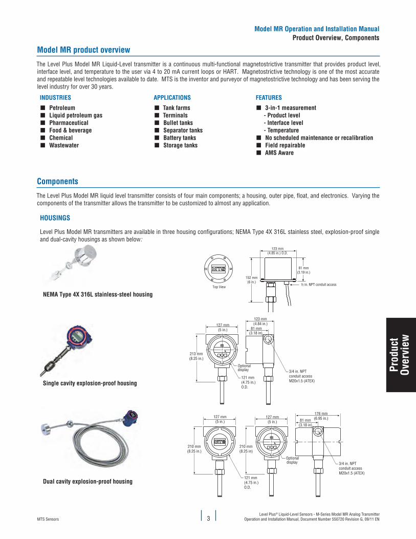
The Level Plus Model MR liquid level transmitter consists of four main components; a housing, outer pipe, float, and electronics. Varying the components of the transmitter allows the transmitter to be customized to almost any application.
hOuSINGS
Level Plus Model MR transmitters are available in three housing configurations; NEMA Type 4X 316L stainless steel, explosion-proof single and dual-cavity housings as shown below:
NeMa Type 4X 316l stainless-steel housingTop View
123 mm(4.85 in.) O.D.
81 mm(3.19 in.)
152 mm(6 in.)
½ in. NPT conduit access
Single cavity explosion-proof housing
127 mm(5 in.)
213 mm(8.25 in.)
123 mm(4.84 in.)
81 mm(3.18 in)
Optionaldisplay 3/4 in. NPT
conduit accessM20x1.5 (ATEX)
121 mm(4.75 in.)O.D.
Dual cavity explosion-proof housing
127 mm(5 in.)
210 mm(8.25 in.)
127 mm(5 in.)
210 mm(8.25 in)
176 mm(6.95 in.)81 mm
(3.18 in)
Optionaldisplay 3/4 in. NPT
conduit accessM20x1.5 (ATEX)
121 mm(4.75 in.)O.D.
Prod
uct
Over
view
Model MR Operation and Installation ManualProduct Overview, components
MTS SensorsLevel Plus® Liquid-Level Sensors - M-Series Model MR Analog Transmitter Operation and Installation Manual, Document Number 550720 Revision G, 09/11 EN 4
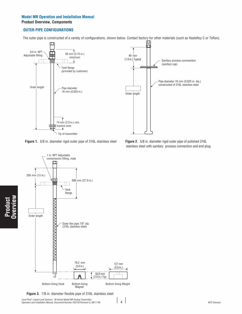
OuTeR PIPe cONfIGuRaTIONS
The outer pipe is constructed of a variety of configurations, shown below. Contact factory for other materials (such as Hastelloy C or Teflon).
74 mm (2.9 in.) min.Inactive zone
3/4 in. NPTAdjustable fitting
Tip of transmitter
Tank flange(provided by customer)
Order length
95 mm (3.75 in.)minimum
Pipe diameter16 mm (0.625 in.)
figure 1. 5/8 in. diameter rigid outer pipe of 316L stainless steel
Sanitary process connnection (sanitary cap)
Pipe diameter 16 mm (0.625 in. dia.)constructed of 316L stainless steel
Order length
49 mm(1.9 in.) Typical
figure 2. 5/8 in. diameter rigid outer pipe of polished 316L stainless steel with sanitary process connection and end plug
Order length
Outer flex pipe 7/8” dia.(316L stainless steel)
305 mm (12 in.)
686 mm (27.0 in.)
Tankflange
1 in. NPT Adjustablecompression fitting, male
Bottom-fixingMagnet
Bottom-fixing WeightBottom-fixing Hook
76.2 mm(3.0 in.)
127 mm(5.0 in.)
50.8 mm(2.0 in.) Typ.
figure 3. 7/8 in. diameter flexible pipe of 316L stainless steel
Model MR Operation and Installation ManualProduct Overview, components
Prod
uct
Over
view
MTS SensorsLevel Plus® Liquid-Level Sensors - M-Series Model MR Analog Transmitter
Operation and Installation Manual, Document Number 550720 Revision G, 09/11 EN5
flOaTS
Model MR transmitters offer numerous floats for different applica-tions such as stainless steel, 3-A sanitary, hastelloy, Teflon, and Nitrophyl for both product level and interface level. To be able to accurately detect the interface level there needs to be a difference of at least 0.05 in specific gravities between the product and interface liquids. For detailed information about floats, refer to the ‘Acces-sories Catalog’, MTS part number 551103.
For assistance with selecting a specific float for your application, please contact Technical Support with the following information:
• Specific gravity of liquid(s) being measured
• Process temperature • Process Opening Size
• Vessel pressure
INTeRNal elecTRONIcS
All transmitters come with two electronic components of a sensing element and a board set. All sensing elements up to 300 inches (7620 mm) are rigid and greater lengths have flexible sensing ele-ments. Flexible sensing elements are only available under 300 inches
(7620 mm) as special orders. The board set consists of a electronic puck and interconnect board. The board set can be configured for single or dual loop output offering the ability to output the product level, interface level, and temperature. All three variables can be communicated via HART.
The electronic puck can be ordered with or without a display. The optional display is capable of displaying the product level, interface level, and temperature. Designed into the optional display are three push buttons for local setup of 4 and 20 mA set points.
A temperature sensing function is optional with the Model MR trans-mitter. The temperature sensing device is a Resistive Temperature Device (RTD) mounted inside the transmitter’s outer pipe assembly. The RTD is a 1000 ohm platinum film device.
acceSSORIeS
MTS also offers a series of displays, housings, converters, and other accessories, please refer to the ‘Accessories Catalog’, MTS part number 551103.
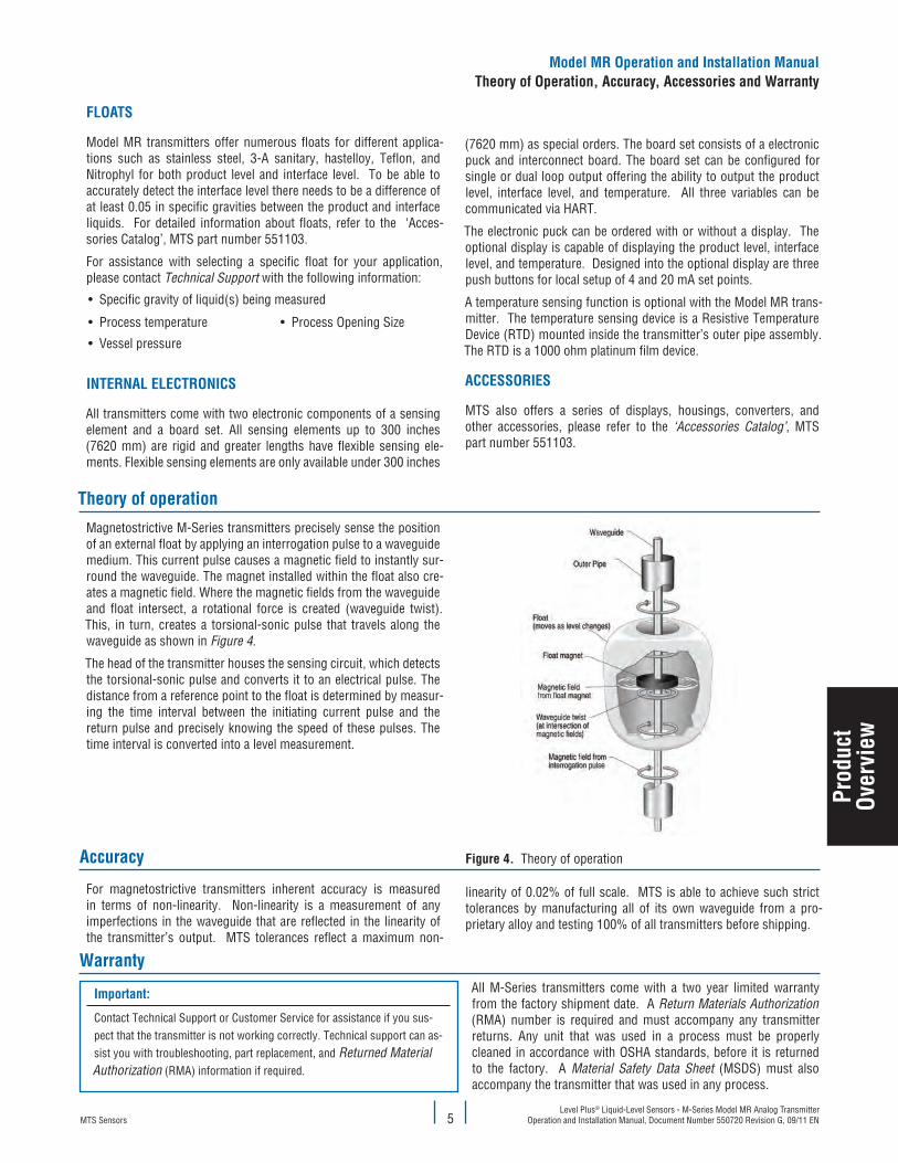
figure 4. Theory of operationaccuracy
For magnetostrictive transmitters inherent accuracy is measured in terms of non-linearity. Non-linearity is a measurement of any imperfections in the waveguide that are reflected in the linearity of the transmitter’s output. MTS tolerances reflect a maximum non-
linearity of 0.02% of full scale. MTS is able to achieve such strict tolerances by manufacturing all of its own waveguide from a pro-prietary alloy and testing 100% of all transmitters before shipping.
Warranty
Magnetostrictive M-Series transmitters precisely sense the position of an external float by applying an interrogation pulse to a waveguide medium. This current pulse causes a magnetic field to instantly sur-round the waveguide. The magnet installed within the float also cre-ates a magnetic field. Where the magnetic fields from the waveguide and float intersect, a rotational force is created (waveguide twist). This, in turn, creates a torsional-sonic pulse that travels along the waveguide as shown in Figure 4.
The head of the transmitter houses the sensing circuit, which detects the torsional-sonic pulse and converts it to an electrical pulse. The distance from a reference point to the float is determined by measur-ing the time interval between the initiating current pulse and the return pulse and precisely knowing the speed of these pulses. The time interval is converted into a level measurement.
Theory of operation
Important:
Contact Technical Support or Customer Service for assistance if you sus-pect that the transmitter is not working correctly. Technical support can as-sist you with troubleshooting, part replacement, and Returned Material Authorization (RMA) information if required.
All M-Series transmitters come with a two year limited warranty from the factory shipment date. A Return Materials Authorization (RMA) number is required and must accompany any transmitter returns. Any unit that was used in a process must be properly cleaned in accordance with OSHA standards, before it is returned to the factory. A Material Safety Data Sheet (MSDS) must also accompany the transmitter that was used in any process.
Model MR Operation and Installation ManualTheory of Operation, accuracy, accessories and Warranty
Prod
uct
Over
view
MTS SensorsLevel Plus® Liquid-Level Sensors - M-Series Model MR Analog Transmitter Operation and Installation Manual, Document Number 550720 Revision G, 09/11 EN 6
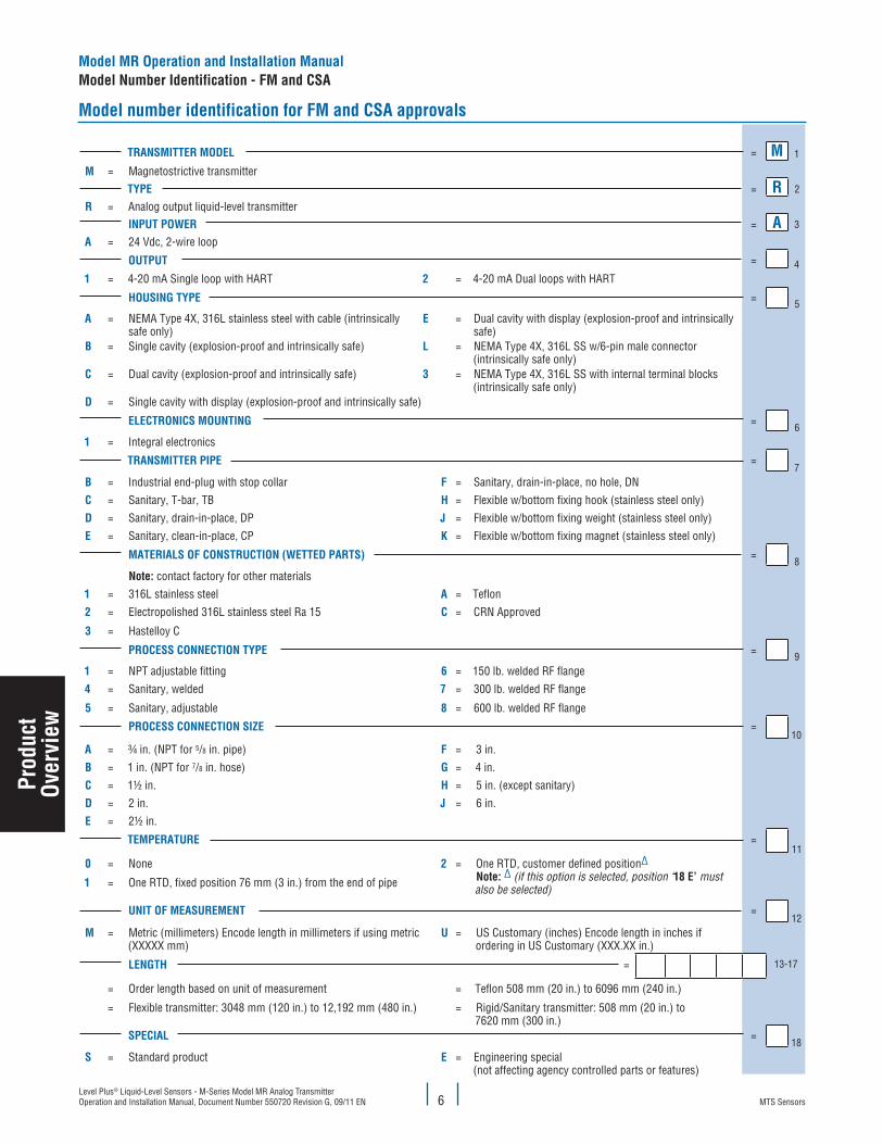
Model number identification for fM and cSa approvals
TRaNSMITTeR MODel = M 1
M = Magnetostrictive transmitterTyPe = R 2
R = Analog output liquid-level transmitterINPuT POWeR = a 3
a = 24 Vdc, 2-wire loop
OuTPuT = 41 = 4-20 mA Single loop with HART 2 = 4-20 mA Dual loops with HART
hOuSING TyPe = 5a = NEMA Type 4X, 316L stainless steel with cable (intrinsically
safe only)e = Dual cavity with display (explosion-proof and intrinsically
safe)B = Single cavity (explosion-proof and intrinsically safe) l = NEMA Type 4X, 316L SS w/6-pin male connector
(intrinsically safe only)c = Dual cavity (explosion-proof and intrinsically safe) 3 = NEMA Type 4X, 316L SS with internal terminal blocks
(intrinsically safe only)D = Single cavity with display (explosion-proof and intrinsically safe)
elecTRONIcS MOuNTING =6
1 = Integral electronics
TRaNSMITTeR PIPe =7
B = Industrial end-plug with stop collar f = Sanitary, drain-in-place, no hole, DNc = Sanitary, T-bar, TB h = Flexible w/bottom fixing hook (stainless steel only)
D = Sanitary, drain-in-place, DP J = Flexible w/bottom fixing weight (stainless steel only)e = Sanitary, clean-in-place, CP k = Flexible w/bottom fixing magnet (stainless steel only)
MaTeRIalS Of cONSTRucTION (WeTTeD PaRTS) =8
Note: contact factory for other materials1 = 316L stainless steel a = Teflon2 = Electropolished 316L stainless steel Ra 15 c = CRN Approved
3 = Hastelloy C
PROceSS cONNecTION TyPe = 91 = NPT adjustable fitting 6 = 150 lb. welded RF flange4 = Sanitary, welded 7 = 300 lb. welded RF flange
5 = Sanitary, adjustable 8 = 600 lb. welded RF flange
PROceSS cONNecTION SIze =10
a = ¾ in. (NPT for 5/8 in. pipe) f = 3 in.
B = 1 in. (NPT for 7/8 in. hose) G = 4 in.c = 1½ in. h = 5 in. (except sanitary)
D = 2 in. J = 6 in.
e = 2½ in.
TeMPeRaTuRe =11
0 = None 2 = One RTD, customer defined position∆ Note: ∆ (if this option is selected, position ‘18 e’ must also be selected)1 = One RTD, fixed position 76 mm (3 in.) from the end of pipe
uNIT Of MeaSuReMeNT =12
M = Metric (millimeters) Encode length in millimeters if using metric (XXXXX mm)
u = US Customary (inches) Encode length in inches if ordering in US Customary (XXX.XX in.)
leNGTh = 13-17
= Order length based on unit of measurement = Teflon 508 mm (20 in.) to 6096 mm (240 in.)
= Flexible transmitter: 3048 mm (120 in.) to 12,192 mm (480 in.) = Rigid/Sanitary transmitter: 508 mm (20 in.) to 7620 mm (300 in.)
SPecIal =18
S = Standard product e = Engineering special (not affecting agency controlled parts or features)
Model MR Operation and Installation ManualModel Number Identification - fM and cSa
Prod
uct
Over
view
MTS SensorsLevel Plus® Liquid-Level Sensors - M-Series Model MR Analog Transmitter
Operation and Installation Manual, Document Number 550720 Revision G, 09/11 EN7
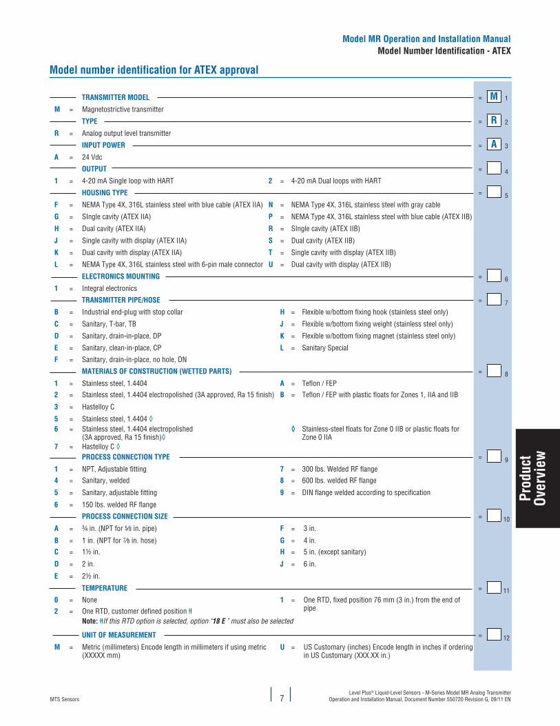
TRaNSMITTeR MODel = M 1
M = Magnetostrictive transmitter
TyPe = R 2
R = Analog output level transmitter
INPuT POWeR = a 3
a = 24 Vdc
OuTPuT = 41 = 4-20 mA Single loop with HART 2 = 4-20 mA Dual loops with HART
hOuSING TyPe = 5f = NEMA Type 4X, 316L stainless steel with blue cable (ATEX IIA) N = NEMA Type 4X, 316L stainless steel with gray cable
G = SIngle cavity (ATEX IIA) P = NEMA Type 4X, 316L stainless steel with blue cable (ATEX IIB)
h = Dual cavity (ATEX IIA) R = SIngle cavity (ATEX IIB)
J = Single cavity with display (ATEX IIA) S = Dual cavity (ATEX IIB)
k = Dual cavity with display (ATEX IIA) T = Single cavity with display (ATEX IIB)
l = NEMA Type 4X, 316L stainless steel with 6-pin male connector u = Dual cavity with display (ATEX IIB)
elecTRONIcS MOuNTING = 61 = Integral electronics
TRaNSMITTeR PIPe/hOSe = 7B = Industrial end-plug with stop collar h = Flexible w/bottom fixing hook (stainless steel only)
c = Sanitary, T-bar, TB J = Flexible w/bottom fixing weight (stainless steel only)
D = Sanitary, drain-in-place, DP k = Flexible w/bottom fixing magnet (stainless steel only)
e = Sanitary, clean-in-place, CP l = Sanitary Special
f = Sanitary, drain-in-place, no hole, DN
MaTeRIalS Of cONSTRucTION (WeTTeD PaRTS) = 81 = Stainless steel, 1.4404 a = Teflon / FEP2 = Stainless steel, 1.4404 electropolished (3A approved, Ra 15 finish) B = Teflon / FEP with plastic floats for Zones 1, IIA and IIB
3 = Hastelloy C
5 = Stainless steel, 1.4404 ◊6 = Stainless steel, 1.4404 electropolished
(3A approved, Ra 15 finish)◊◊ Stainless-steel floats for Zone 0 IIB or plastic floats for
Zone 0 IIA7 = Hastelloy C ◊
PROceSS cONNecTION TyPe = 91 = NPT, Adjustable fitting 7 = 300 lbs. Welded RF flange4 = Sanitary, welded 8 = 600 lbs. welded RF flange
5 = Sanitary, adjustable fitting 9 = DIN flange welded according to specification
6 = 150 lbs. welded RF flange
PROceSS cONNecTION SIze = 10a = ¾ in. (NPT for 5∕8 in. pipe) f = 3 in.
B = 1 in. (NPT for 7∕8 in. hose) G = 4 in.
c = 1½ in. h = 5 in. (except sanitary)
D = 2 in. J = 6 in.
e = 2½ in.
TeMPeRaTuRe = 110 = None 1 = One RTD, fixed position 76 mm (3 in.) from the end of
pipe2 = One RTD, customer defined position łłNote: łłIf this RTD option is selected, option ‘18 E ’ must also be selected
uNIT Of MeaSuReMeNT = 12M = Metric (millimeters) Encode length in millimeters if using metric
(XXXXX mm)u = US Customary (inches) Encode length in inches if ordering
in US Customary (XXX.XX in.)
Model number identification for aTeX approval
Model MR Operation and Installation ManualModel Number Identification - aTeX
Prod
uct
Over
view
MTS SensorsLevel Plus® Liquid-Level Sensors - M-Series Model MR Analog Transmitter Operation and Installation Manual, Document Number 550720 Revision G, 09/11 EN 8
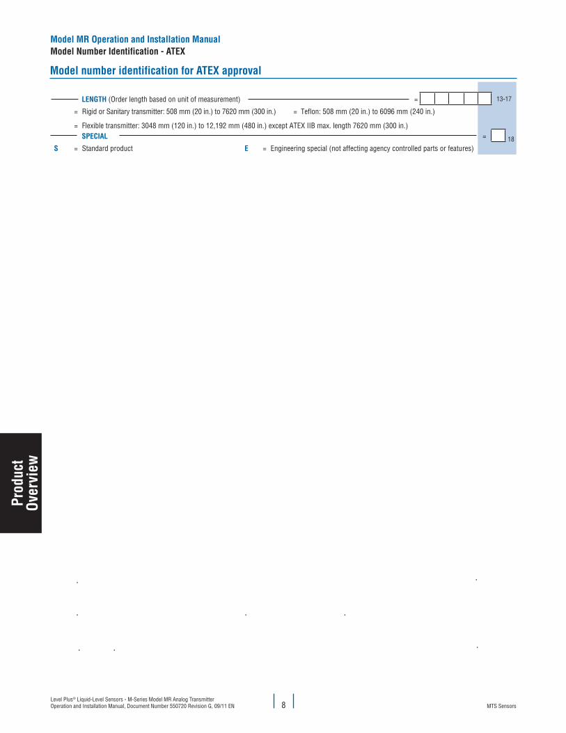
leNGTh (Order length based on unit of measurement) = 13-17
= Rigid or Sanitary transmitter: 508 mm (20 in.) to 7620 mm (300 in.) = Teflon: 508 mm (20 in.) to 6096 mm (240 in.)
= Flexible transmitter: 3048 mm (120 in.) to 12,192 mm (480 in.) except ATEX IIB max. length 7620 mm (300 in.)SPecIal = 18
S = Standard product e = Engineering special (not affecting agency controlled parts or features)
Model number identification for aTeX approval
Model MR Operation and Installation ManualModel Number Identification - aTeX
Prod
uct
Over
view
MTS SensorsLevel Plus® Liquid-Level Sensors - M-Series Model MR Analog Transmitter
Operation and Installation Manual, Document Number 550720 Revision G, 09/11 EN9
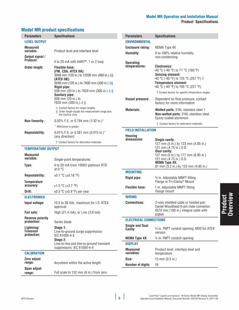
Model MR product specificationsParameters Specifications
level OuTPuT
Measured variable: Product level and interface level
Output signal /Protocol: 4 to 20 mA with HART®, 1 or 2 loop
Order length: flexible hose: (fM, cSa, aTeX IIa):3048 mm (120 in.) to 12200 mm (480 in.) ∆§(aTeX IIB):3048 mm (120 in.) to 7600 mm (300 in.) ∆§Rigid pipe:508 mm (20 in.) to 7620 mm (300 in.) ∆ §Sanitary pipe: 508 mm (20 in.) to 7620 mm (300 in.) ∆ §
∆ Contact factory for longer lengths.§ Order length equals the measurement range plus
the inactive zone.
Non-linearity: 0.02% F.S. or 0.794 mm (1/32 in.)*
* Whichever is greater
Repeatability: 0.01% F.S. or 0.381 mm (0.015 in.)*(any direction)
† Contact factory for alternative materials.
TeMPeRaTuRe OuTPuT
Measured variable: Single-point temperatures
Type: 4 to 20 mA from 1000Ω platinum RTD at 0 °C
Repeatability: ±0.1 °C (±0.18 °F)
Temperature accuracy: ±1.5 °C (±2.7 °F)
Drift: ±0.5 ºC (±0.9 ºF) per year
elecTRONIcS
Input voltage: 10.5 to 36 Vdc, maximum for I.S. ATEX approval
fail safe: High (21.4 mA), or Low (3.8 mA)
Reverse polarity protection: Series diode
lightning/Transient protection:
Stage 1: Line-to-ground surge suppression; IEC 61000-4-5Stage 2: Line-to-line and line-to-ground transient suppressors; IEC 61000-4-4
calIBRaTION
zero adjust range: Anywhere within the active length
Span adjust range: Full scale to 152 mm (6 in.) from zero
Parameters Specifications
eNvIRONMeNTal
enclosure rating: NEMA Type 4X
humidity: 0 to 100% relative humidity, non-condensing
Operating temperatures: electronics:
-40 °C (-40 °F) to 71 °C (160 ºF)Sensing element:
-40 °C (-40 °F) to 125 °C (257 °F) ◊Temperature element:
-40 °C (-40 °F) to 105 °C (221 °F)
◊ Contact factory for specific temperature ranges.
vessel pressure: Dependent on float pressure, contact factory for more information
Materials: Wetted parts: 316L stainless steel †Non-wetted parts: 316L stainless steel, Epoxy coated aluminum
† Contact factory for alternative materials.
fIelD INSTallaTION
housing dimensions: Single cavity:
127 mm (5 in.) by 123 mm (4.85 in.) 121 mm (4.75 in.) O.D.Dual cavity:127 mm (5 in.) by 177 mm (6.95 in.) 121 mm (4.75 in.) O.D.NeMa Type 4X:81 mm (3.2 in.) by 123 mm (4.85 in.)
MOuNTING
Rigid pipe: ¾ in. Adjustable MNPT fittingFlange or Tri-Clamp® Mount
flexible hose: 1 in. Adjustable MNPT fittingFlange mount
WIRING
connections: 2-wire shielded cable or twisted pair,Daniel Woodhead 6-pin male connector,4570 mm (180 in.) integral cable with pigtail
elecTRIcal cONNecTIONS
Single and Dual cavity: ¾ in. FNPT conduit opening, M20 for ATEX
version
NeMa Type 4X: ½ in. FNPT conduit opening
DISPlay
Measured variables:
Product level, interface level and temperature
Size: 13 mm (0.5 in.)
Number of digits: 16
Model MR Operation and Installation ManualProduct Specifications
Prod
uct
Over
view
MTS SensorsLevel Plus® Liquid-Level Sensors - M-Series Model MR Analog Transmitter Operation and Installation Manual, Document Number 550720 Revision G, 09/11 EN 10
Installation and mounting
This section contains information about storing your transmitter (prior to installation) and detailed procedures for installing and mounting your transmitter.
Storage
If storage is required prior to installation, store indoors in a dry environment at ambient temperature range not exceeding -40 °C (-40 °F) to 71 °C (160 °F).
Stilling wells and guide poles
Level Plus transmitters can be mounted in slotted or unslotted stilling wells but a slotted stilling well is always preferred. Using a unslotted stilling well will negatively affect performance of any level device as the level in the stilling well can differ from the level in the tank. The Level Plus transmitter can also be installed to one side of the stilling well to also allow for sampling and manual gauging from the same opening as the automatic tank gauging. Contact Technical Support for details.
Level Plus transmitters do not require a stilling well for installation. Our transmitters are installed in numerous tanks without stilling wells with no loss in performance due to our patented flexible waveguide and hose. A stilling well is highly recommended for agitated, turbulent, and/or fast filling tanks.
Installation
The installation procedures below are illustrated using the adjustable NPT fitting for a threaded flange mount. The procedures will have to be slightly adjusted if using a welded flange or sanitary Tri-Clamp mount.
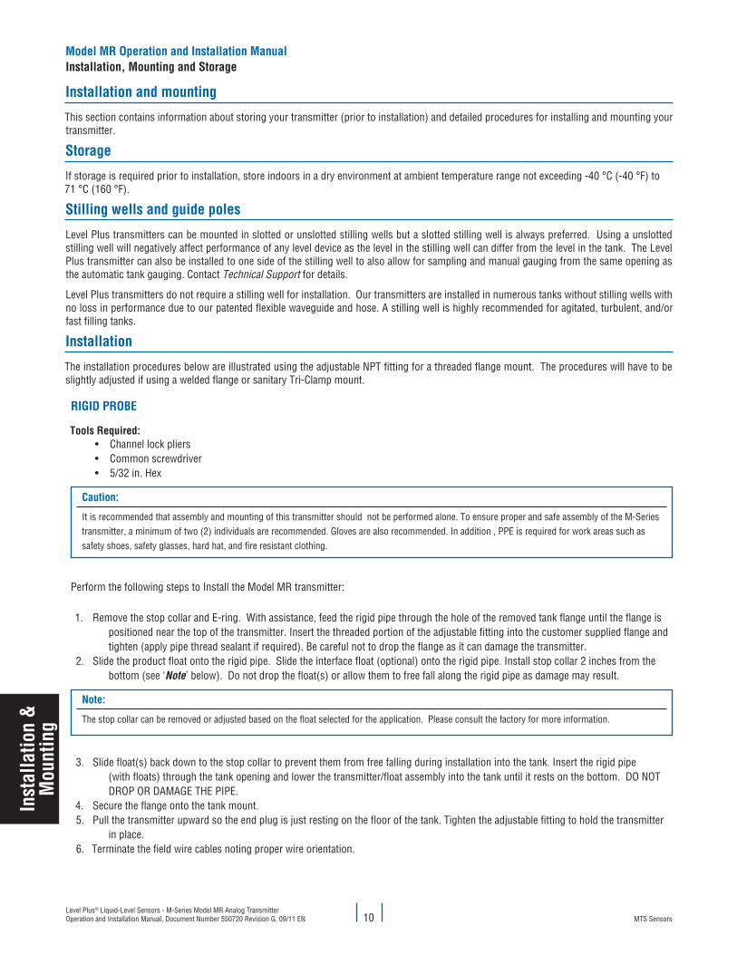
RIGID PROBe
Tools Required:• Channel lock pliers• Common screwdriver• 5/32 in. Hex
caution:
It is recommended that assembly and mounting of this transmitter should not be performed alone. To ensure proper and safe assembly of the M-Series transmitter, a minimum of two (2) individuals are recommended. Gloves are also recommended. In addition , PPE is required for work areas such as safety shoes, safety glasses, hard hat, and fire resistant clothing.
Perform the following steps to Install the Model MR transmitter:
1. Remove the stop collar and E-ring. With assistance, feed the rigid pipe through the hole of the removed tank flange until the flange is positioned near the top of the transmitter. Insert the threaded portion of the adjustable fitting into the customer supplied flange and tighten (apply pipe thread sealant if required). Be careful not to drop the flange as it can damage the transmitter.
2. Slide the product float onto the rigid pipe. Slide the interface float (optional) onto the rigid pipe. Install stop collar 2 inches from the bottom (see ‘Note’ below). Do not drop the float(s) or allow them to free fall along the rigid pipe as damage may result.
Note:
The stop collar can be removed or adjusted based on the float selected for the application. Please consult the factory for more information.
3. Slide float(s) back down to the stop collar to prevent them from free falling during installation into the tank. Insert the rigid pipe (with floats) through the tank opening and lower the transmitter/float assembly into the tank until it rests on the bottom. DO NOT DROP OR DAMAGE THE PIPE.4. Secure the flange onto the tank mount.5. Pull the transmitter upward so the end plug is just resting on the floor of the tank. Tighten the adjustable fitting to hold the transmitter
in place.6. Terminate the field wire cables noting proper wire orientation.
Model MR Operation and Installation ManualInstallation, Mounting and Storage
Inst
alla
tion
&
Mou
ntin
g
MTS SensorsLevel Plus® Liquid-Level Sensors - M-Series Model MR Analog Transmitter
Operation and Installation Manual, Document Number 550720 Revision G, 09/11 EN11
fleXIBle PROBe
caution:
When assembling and installing the Model MR transmitter, be careful not to allow the flexible hose to kink or be coiled in less than 16 in. (406.5 mm) diameter. It is recommended that assembly and mounting of this transmitter should not be done alone. To ensure proper and safe assembly of the Model MR transmitter, a minimum of two (2) individuals are recommended. Gloves are also recommended. PPE is required for work areas such as safe-ty shoes, safety glasses, hard hat, and fire resistant clothing.
Tools Required:
• 9/16 in. Socket and ratchet• Channel lock pliers• 3/16 in. Hex
1. Remove the stop collar. With assistance, feed the flexible hose through the hole of the removed tank flange until the flange is positioned at the rigid section of pipe near the top of the transmitter. Insert the threaded portion of the adjustable fitting into the customer supplied flange and tighten (apply pipe thread sealant if required). Be careful not to drop flange on the flexible hose as damage may result.
2. Slide the product float onto the flexible pipe. Slide the interface float (optional) onto the flexible pipe. Install stop collar 3 inches from the bottom of rigid section (see ‘Note’ below). Do not drop float(s) or allow them to free fall along the flexible pipe as damage may result.
Note:
The stop collar can be removed or adjusted based on the float selected for the application. Please consult the factory for more information.
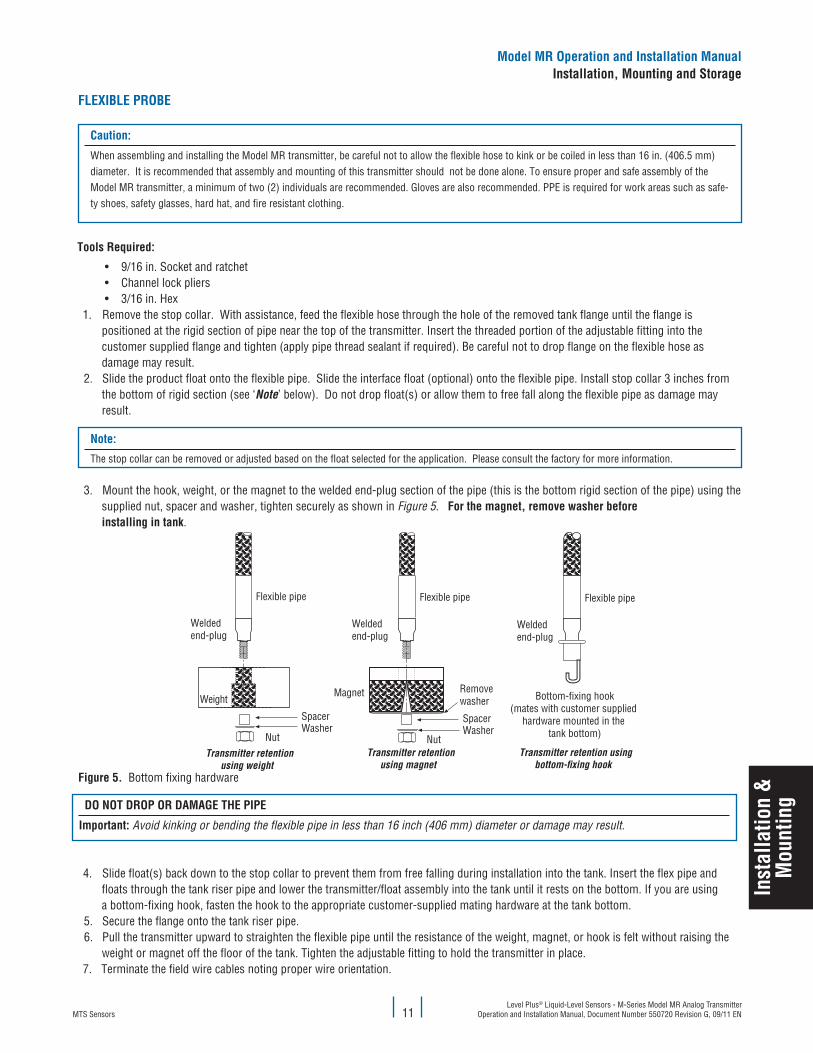
3. Mount the hook, weight, or the magnet to the welded end-plug section of the pipe (this is the bottom rigid section of the pipe) using the supplied nut, spacer and washer, tighten securely as shown in Figure 5. for the magnet, remove washer before installing in tank.
Weight
Flexible pipe
Magnet
Transmitter retentionusing weight
Bottom-fixing hook(mates with customer supplied
hardware mounted in the tank bottom)Nut
Weldedend-plug
WasherSpacer
Flexible pipe
Weldedend-plug
NutWasherSpacer
Flexible pipe
Weldedend-plug
Transmitter retentionusing magnet
Transmitter retention usingbottom-xing hook
Removewasher
figure 5. Bottom fixing hardware
DO NOT DROP OR DaMaGe The PIPe
Important: Avoid kinking or bending the flexible pipe in less than 16 inch (406 mm) diameter or damage may result.
4. Slide float(s) back down to the stop collar to prevent them from free falling during installation into the tank. Insert the flex pipe and floats through the tank riser pipe and lower the transmitter/float assembly into the tank until it rests on the bottom. If you are using a bottom-fixing hook, fasten the hook to the appropriate customer-supplied mating hardware at the tank bottom.
5. Secure the flange onto the tank riser pipe.6. Pull the transmitter upward to straighten the flexible pipe until the resistance of the weight, magnet, or hook is felt without raising the
weight or magnet off the floor of the tank. Tighten the adjustable fitting to hold the transmitter in place. 7. Terminate the field wire cables noting proper wire orientation.
Model MR Operation and Installation ManualInstallation, Mounting and Storage
Inst
alla
tion
&M
ount
ing
MTS SensorsLevel Plus® Liquid-Level Sensors - M-Series Model MR Analog Transmitter Operation and Installation Manual, Document Number 550720 Revision G, 09/11 EN 12
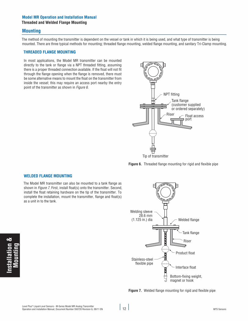
Mounting
The method of mounting the transmitter is dependent on the vessel or tank in which it is being used, and what type of transmitter is being mounted. There are three typical methods for mounting; threaded flange mounting, welded flange mounting, and sanitary Tri-Clamp mounting.
ThReaDeD flaNGe MOuNTING
In most applications, the Model MR transmitter can be mounted directly to the tank or flange via a NPT threaded fitting, assuming there is a proper threaded connection available. If the float will not fit through the flange opening when the flange is removed, there must be some alternative means to mount the float on the transmitter from inside the vessel; this may require an access port nearby the entry point of the transmitter as shown in Figure 6.
Riser
NPT fitting
Tank flange(customer suppliedor ordered separately)
Float accessport
Tip of transmitter
figure 6. Threaded flange mounting for rigid and flexible pipe
WelDeD flaNGe MOuNTING
The Model MR transmitter can also be mounted to a tank flange as shown in Figure 7. First, install float(s) onto the transmitter. Second, install the float retaining hardware on the tip of the transmitter. To complete the installation, mount the transmitter, flange and float(s) as a unit in to the tank.
Welded flange
Tank flange
Welding sleeve28.6 mm
(1.125 in.) dia
Product float
Riser
Stainless-steelflexible pipe
Interface float
Bottom-fixing weight,magnet or hook
figure 7. Welded flange mounting for rigid and flexible pipe
Model MR Operation and Installation ManualThreaded and Welded flange Mounting
Inst
alla
tion
&
Mou
ntin
g
MTS SensorsLevel Plus® Liquid-Level Sensors - M-Series Model MR Analog Transmitter
Operation and Installation Manual, Document Number 550720 Revision G, 09/11 EN13
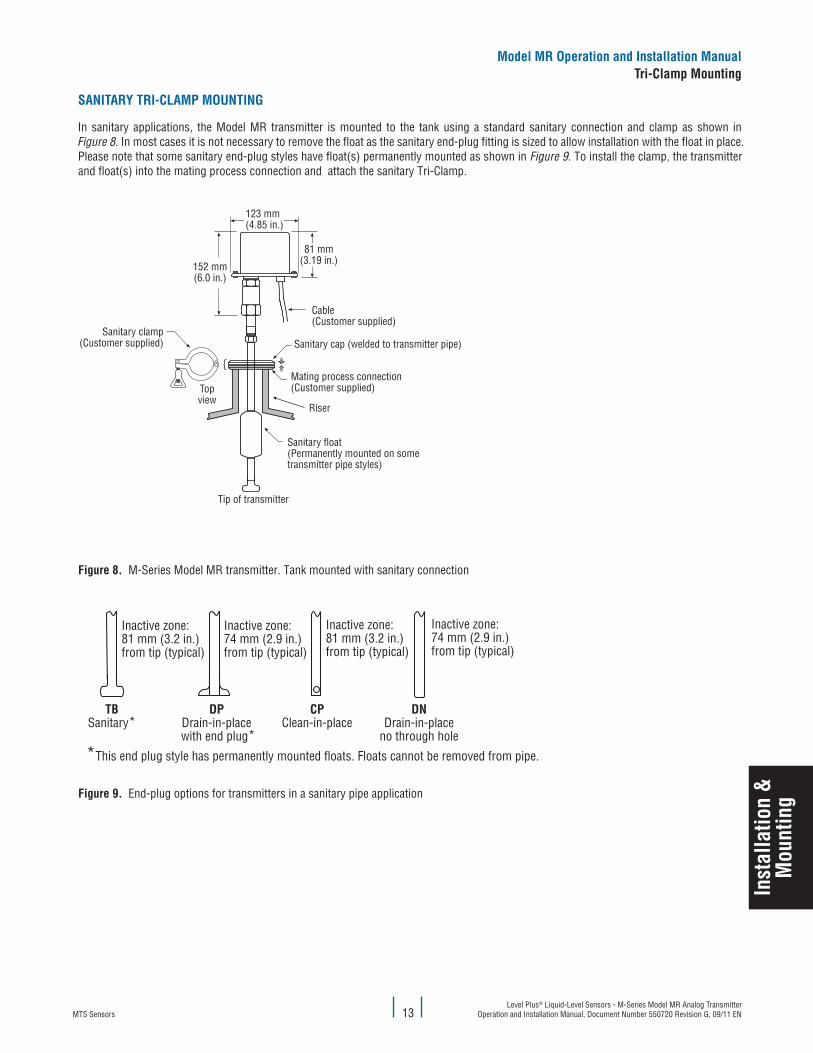
SaNITaRy TRI-claMP MOuNTING
In sanitary applications, the Model MR transmitter is mounted to the tank using a standard sanitary connection and clamp as shown in Figure 8. In most cases it is not necessary to remove the float as the sanitary end-plug fitting is sized to allow installation with the float in place. Please note that some sanitary end-plug styles have float(s) permanently mounted as shown in Figure 9. To install the clamp, the transmitter and float(s) into the mating process connection and attach the sanitary Tri-Clamp.
Mating process connection(Customer supplied)Top
view
Cable(Customer supplied)
123 mm(4.85 in.)
Riser
Sanitary float(Permanently mounted on some transmitter pipe styles)
81 mm(3.19 in.)152 mm
(6.0 in.)
Tip of transmitter
Sanitary clamp(Customer supplied) Sanitary cap (welded to transmitter pipe)
figure 8. M-Series Model MR transmitter. Tank mounted with sanitary connection
CPClean-in-place
DPDrain-in-place
with end plug*
TBSanitary*
Inactive zone:81 mm (3.2 in.)from tip (typical)
*This end plug style has permanently mounted floats. Floats cannot be removed from pipe.
DNDrain-in-place
no through hole
Inactive zone:74 mm (2.9 in.)from tip (typical)
Inactive zone:74 mm (2.9 in.)from tip (typical)
Inactive zone:81 mm (3.2 in.)from tip (typical)
figure 9. End-plug options for transmitters in a sanitary pipe application
Model MR Operation and Installation ManualTri-clamp Mounting
Inst
alla
tion
&M
ount
ing
MTS SensorsLevel Plus® Liquid-Level Sensors - M-Series Model MR Analog Transmitter Operation and Installation Manual, Document Number 550720 Revision G, 09/11 EN 14
electrical connections and wiring procedures
A typical intrinsically safe connection for the Level Plus Model MR transmitter includes protective safety barriers, a power supply and a reading or monitoring device. Refer to Agency information for detailed information.
A typical explosion proof connection for the Model MR transmitter includes a power supply and a reading or monitoring device connected using explosion proof conduit. Refer to Agency information for detailed information.
Notes:
For explosion proof installation, safety barriers are not required and wiring shall be installed in accordance with the National Electric Code ANSI/NFPA 70, Article 501-30 or the regional equivalent.
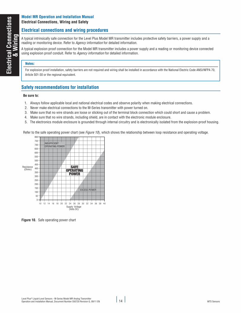
Safety recommendations for installation
Be sure to:
1. Always follow applicable local and national electrical codes and observe polarity when making electrical connections. 2. Never make electrical connections to the M-Series transmitter with power turned on. 3. Make sure that no wire strands are loose or sticking out of the terminal block connection which could short and cause a problem. 4. Make sure that no wire strands, including shield, are in contact with the electronic module enclosure. 5. The electronics module enclosure is grounded through internal circuitry and is electronically isolated from the explosion-proof housing.
Refer to the safe operating power chart (see Figure 10), which shows the relationship between loop resistance and operating voltage.800
750
700
650
600
550
500
450
400
350
300
250
200
150
100
50
0
10 12 14 16 18 20 22 24 26 28 30 32 34 36 38 40
INSUFFICIENTOPERATING POWER
EXCESS POWER
Resistance(Ohms)
Supply Voltage (Volts DC)
figure 10. Safe operating power chart
Model MR Operation and Installation Manualelectrical connections, Wiring and Safety
elec
trica
l con
nect
ions
&
Wiri
ng
MTS SensorsLevel Plus® Liquid-Level Sensors - M-Series Model MR Analog Transmitter
Operation and Installation Manual, Document Number 550720 Revision G, 09/11 EN15
Recommended cable types
Refer to ‘Table 1’ below for general requirements of cable types for the Level Plus Model MR analog transmitter.
caBle SPecIfIcaTIONS
Parameter Specification
Minimum cable size 24 AWG or heavier (0.51 mm diameter)Contact factory for assistance selecting proper cable.
cable type Single pair shielded or multiple pair with overall shield
Maximum cable length Twisted pair: 10,000 ft. (3,048 m)Multiple twisted pair: 5,000 ft. (1,524 m)
Maximum cable length formula Use the following formula to determine the maximum cable length for a specific application:
Where: L = [(65 x 106) ÷ (R x C)] - [(Cf + 10,000) ÷ C]L = Length in meters or feetR = Resistance in ohms, current sense resistance plus barrier resistanceC = Cable capacitance in pF/ft, or pF/mCf = Maximum shunt capacitance of smart field devices in pF
Example:Assume a high performing smart transmitter, a control system,and a single pair of shielded wires.R = 250 ohmsC = 50 pF/ 0,3 m (ft)Cf = 5,000 pF
L = [(65 x 106) ÷ 250 x 50)] - [(5,000 + 10,000) ÷ 50]
L = 1,494 m (4,900 ft.)
Table 1. Cable specification and parameters
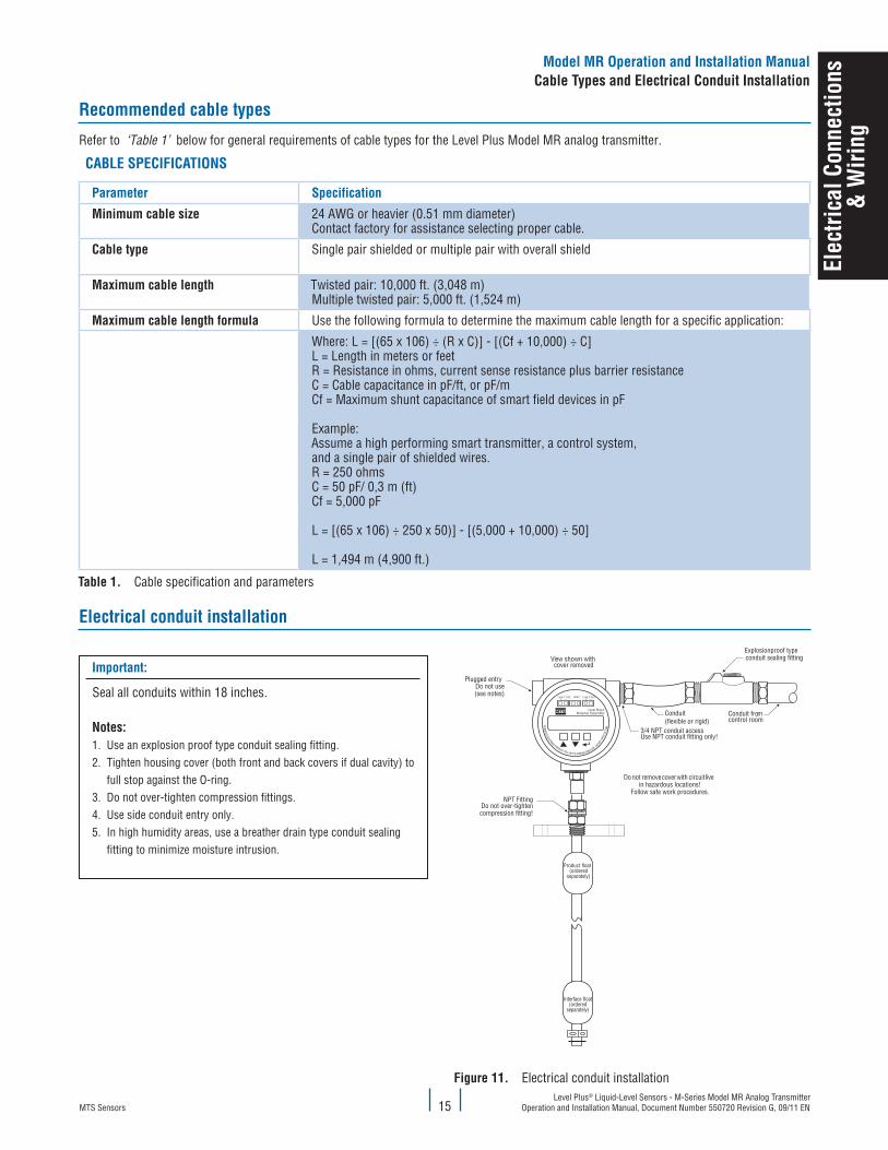
electrical conduit installation
Important:
Seal all conduits within 18 inches.
Notes:1. Use an explosion proof type conduit sealing fitting.2. Tighten housing cover (both front and back covers if dual cavity) to full stop against the O-ring.3. Do not over-tighten compression fittings.4. Use side conduit entry only.5. In high humidity areas, use a breather drain type conduit sealing fitting to minimize moisture intrusion.
NPT FittingDo not over-tightencompression fitting!
Interface float(ordered
separately)
Product float(ordered
separately)
View shown withcover removed
Plugged entryDo not use(see notes)
Do not remove cover with circuit livein hazardous locations!
Follow safe work procedures.
3/4 NPT conduit accessUse NPT conduit fitting only!
Conduit(flexible or rigid)
Explosionproof typeconduit sealing fitting
Conduit fromcontrol room
Loop 1 Test + —
Loop 2 Test + —
HART
Level Plus®M-Series Transmitter
TOREM
OVE ELECTRONICS MODULE, PULL UNIT IN UPWARD DIRECTION -D
ONOTTW
IST O
RTU
RN
figure 11. Electrical conduit installation
Model MR Operation and Installation Manualcable Types and electrical conduit Installation
elec
trica
l con
nect
ions
&
Wiri
ng
MTS SensorsLevel Plus® Liquid-Level Sensors - M-Series Model MR Analog Transmitter Operation and Installation Manual, Document Number 550720 Revision G, 09/11 EN 16
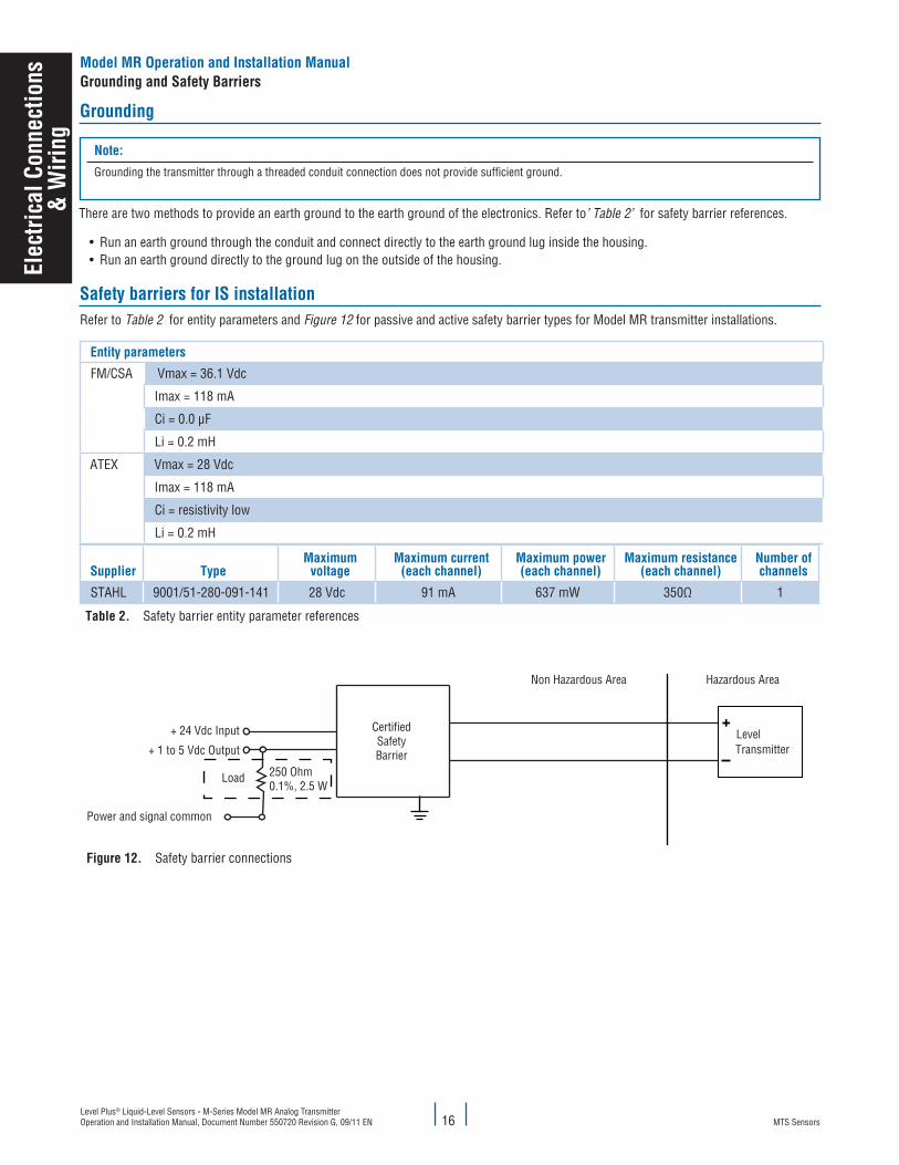
Grounding
Note:
Grounding the transmitter through a threaded conduit connection does not provide sufficient ground.
There are two methods to provide an earth ground to the earth ground of the electronics. Refer to’ Table 2’ for safety barrier references.
• Run an earth ground through the conduit and connect directly to the earth ground lug inside the housing.• Run an earth ground directly to the ground lug on the outside of the housing.
Safety barriers for IS installationRefer to Table 2 for entity parameters and Figure 12 for passive and active safety barrier types for Model MR transmitter installations.
entity parameters
FM/CSA Vmax = 36.1 Vdc
Imax = 118 mA
Ci = 0.0 µF
Li = 0.2 mH
ATEX Vmax = 28 Vdc
Imax = 118 mA
Ci = resistivity low
Li = 0.2 mH
Supplier TypeMaximum
voltageMaximum current
(each channel)Maximum power(each channel)
Maximum resistance(each channel)
Number of channels
STAHL 9001/51-280-091-141 28 Vdc 91 mA 637 mW 350Ω 1
Table 2. Safety barrier entity parameter references
figure 12. Safety barrier connections
Non Hazardous Area Hazardous Area
CertifiedSafetyBarrier
+ 24 Vdc Input LevelTransmitter
Non Hazardous Area Hazardous Area
CertifiedSafety Bariers
24 VdcSupply-Voltage
I (A)
4-20mA
I (A)
4-20mA
24 VdcSupply-Voltage
I.S. Ground connection
CertifiedSafety Bariers
I.S. Ground connection
Transmitter 1
Transmitter 2
+ 1 to 5 Vdc Output
Load 250 Ohm0.1%, 2.5 W
Power and signal common
Model MR Operation and Installation ManualGrounding and Safety Barriers
elec
trica
l con
nect
ions
&
Wiri
ng
MTS SensorsLevel Plus® Liquid-Level Sensors - M-Series Model MR Analog Transmitter
Operation and Installation Manual, Document Number 550720 Revision G, 09/11 EN17
Model MR Operation and Installation ManualMaintenance and field Service / Troubleshooting
Mai
nten
ance
& f
ield
Ser
vice
Trou
bles
hoot
iing
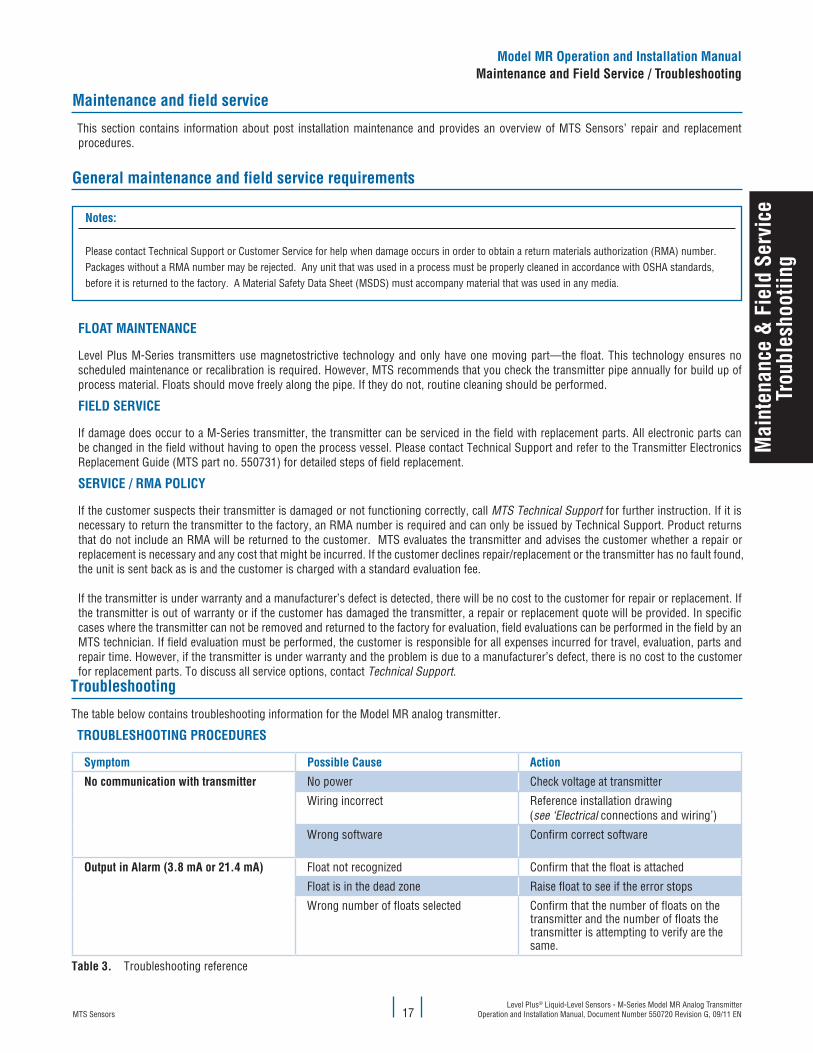
Maintenance and field service
This section contains information about post installation maintenance and provides an overview of MTS Sensors’ repair and replacement procedures.
General maintenance and field service requirements
Notes:
Please contact Technical Support or Customer Service for help when damage occurs in order to obtain a return materials authorization (RMA) number. Packages without a RMA number may be rejected. Any unit that was used in a process must be properly cleaned in accordance with OSHA standards, before it is returned to the factory. A Material Safety Data Sheet (MSDS) must accompany material that was used in any media.
flOaT MaINTeNaNce
Level Plus M-Series transmitters use magnetostrictive technology and only have one moving part—the float. This technology ensures no scheduled maintenance or recalibration is required. However, MTS recommends that you check the transmitter pipe annually for build up of process material. Floats should move freely along the pipe. If they do not, routine cleaning should be performed.
fIelD SeRvIce
If damage does occur to a M-Series transmitter, the transmitter can be serviced in the field with replacement parts. All electronic parts can be changed in the field without having to open the process vessel. Please contact Technical Support and refer to the Transmitter Electronics Replacement Guide (MTS part no. 550731) for detailed steps of field replacement.
SeRvIce / RMa POlIcy
If the customer suspects their transmitter is damaged or not functioning correctly, call MTS Technical Support for further instruction. If it is necessary to return the transmitter to the factory, an RMA number is required and can only be issued by Technical Support. Product returns that do not include an RMA will be returned to the customer. MTS evaluates the transmitter and advises the customer whether a repair or replacement is necessary and any cost that might be incurred. If the customer declines repair/replacement or the transmitter has no fault found, the unit is sent back as is and the customer is charged with a standard evaluation fee.
If the transmitter is under warranty and a manufacturer’s defect is detected, there will be no cost to the customer for repair or replacement. If the transmitter is out of warranty or if the customer has damaged the transmitter, a repair or replacement quote will be provided. In specific cases where the transmitter can not be removed and returned to the factory for evaluation, field evaluations can be performed in the field by an MTS technician. If field evaluation must be performed, the customer is responsible for all expenses incurred for travel, evaluation, parts and repair time. However, if the transmitter is under warranty and the problem is due to a manufacturer’s defect, there is no cost to the customer for replacement parts. To discuss all service options, contact Technical Support.
Troubleshooting
The table below contains troubleshooting information for the Model MR analog transmitter.
TROuBleShOOTING PROceDuReS
Symptom Possible cause action
No communication with transmitter No power Check voltage at transmitter
Wiring incorrect Reference installation drawing (see ‘Electrical connections and wiring’)
Wrong software Confirm correct software
Output in alarm (3.8 ma or 21.4 ma) Float not recognized Confirm that the float is attached
Float is in the dead zone Raise float to see if the error stops
Wrong number of floats selected Confirm that the number of floats on the transmitter and the number of floats the transmitter is attempting to verify are the same.
Table 3. Troubleshooting reference
MTS SensorsLevel Plus® Liquid-Level Sensors - M-Series Model MR Analog Transmitter Operation and Installation Manual, Document Number 550720 Revision G, 09/11 EN 18
Setu
p
Quick start-up guide
BefORe yOu BeGIN
Note:
Output will vary depending on the location of the 4 and 20 mA set points.
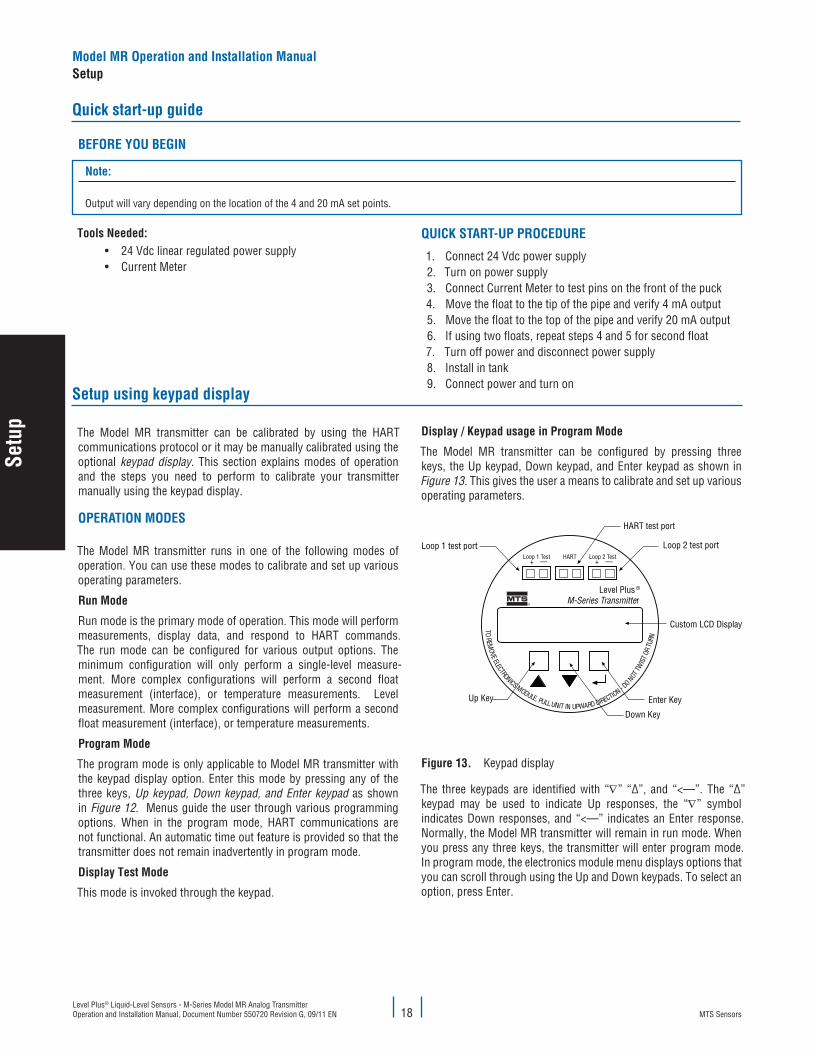
Setup using keypad display
Display / keypad usage in Program Mode
The Model MR transmitter can be configured by pressing three keys, the Up keypad, Down keypad, and Enter keypad as shown in Figure 13. This gives the user a means to calibrate and set up various operating parameters.
Loop 1 Test + —
Loop 2 Test + —
HART
TOREM
OVE ELECTRONICS MODULE, PULLUNIT IN UPWARD DIRECTION - D
ONOTTW
IST O
RTU
RN
Loop 1 test port Loop 2 test port
HART test port
Up Key Enter Key
Down Key
Custom LCD Display
Level Plus ®
M-Series Transmitter
figure 13. Keypad display
The three keypads are identified with “∇” “∆”, and “<—”. The “∆” keypad may be used to indicate Up responses, the “∇” symbol indicates Down responses, and “<—” indicates an Enter response. Normally, the Model MR transmitter will remain in run mode. When you press any three keys, the transmitter will enter program mode. In program mode, the electronics module menu displays options that you can scroll through using the Up and Down keypads. To select an option, press Enter.
Tools Needed:• 24 Vdc linear regulated power supply• Current Meter
QuIck STaRT-uP PROceDuRe
1. Connect 24 Vdc power supply2. Turn on power supply3. Connect Current Meter to test pins on the front of the puck4. Move the float to the tip of the pipe and verify 4 mA output5. Move the float to the top of the pipe and verify 20 mA output6. If using two floats, repeat steps 4 and 5 for second float7. Turn off power and disconnect power supply8. Install in tank9. Connect power and turn on
The Model MR transmitter can be calibrated by using the HART communications protocol or it may be manually calibrated using the optional keypad display. This section explains modes of operation and the steps you need to perform to calibrate your transmitter manually using the keypad display.
OPeRaTION MODeS
The Model MR transmitter runs in one of the following modes of operation. You can use these modes to calibrate and set up various operating parameters.
Run Mode
Run mode is the primary mode of operation. This mode will perform measurements, display data, and respond to HART commands. The run mode can be configured for various output options. The minimum configuration will only perform a single-level measure-ment. More complex configurations will perform a second float measurement (interface), or temperature measurements. Level measurement. More complex configurations will perform a second float measurement (interface), or temperature measurements.
Program Mode
The program mode is only applicable to Model MR transmitter with the keypad display option. Enter this mode by pressing any of the three keys, Up keypad, Down keypad, and Enter keypad as shown in Figure 12. Menus guide the user through various programming options. When in the program mode, HART communications are not functional. An automatic time out feature is provided so that the transmitter does not remain inadvertently in program mode.
Display Test Mode
This mode is invoked through the keypad.
Model MR Operation and Installation ManualSetup
MTS SensorsLevel Plus® Liquid-Level Sensors - M-Series Model MR Analog Transmitter
Operation and Installation Manual, Document Number 550720 Revision G, 09/11 EN19
Setu
p
Notes:
In program mode, the transmitter will not respond to incoming HART commands. This function will prevent a user at a remote terminal from overwriting a parameter that is being entered at the same time from a local site.
Program Mode Timer
After you enter the programming mode, a one-minute timer is started. Each time you press a button, the timer is reset. If you do not press a menu button within one minute, the timer will expire and the transmitter will return to the run mode.
loop 1 and loop 2 Test Ports
Using a standard multi-meter set the meter to DC current and attach across the terminals, loop current can be read directly from ports 1 and 2 (see Figure 14). The current read on the meter should correspond with the data being displayed. These ports allow the loop current to be read directly without having to interrupt power.
haRT Port
This port allows for direct connection of the HART field calibrator or other HART host device as long as there is a load on loop 1.
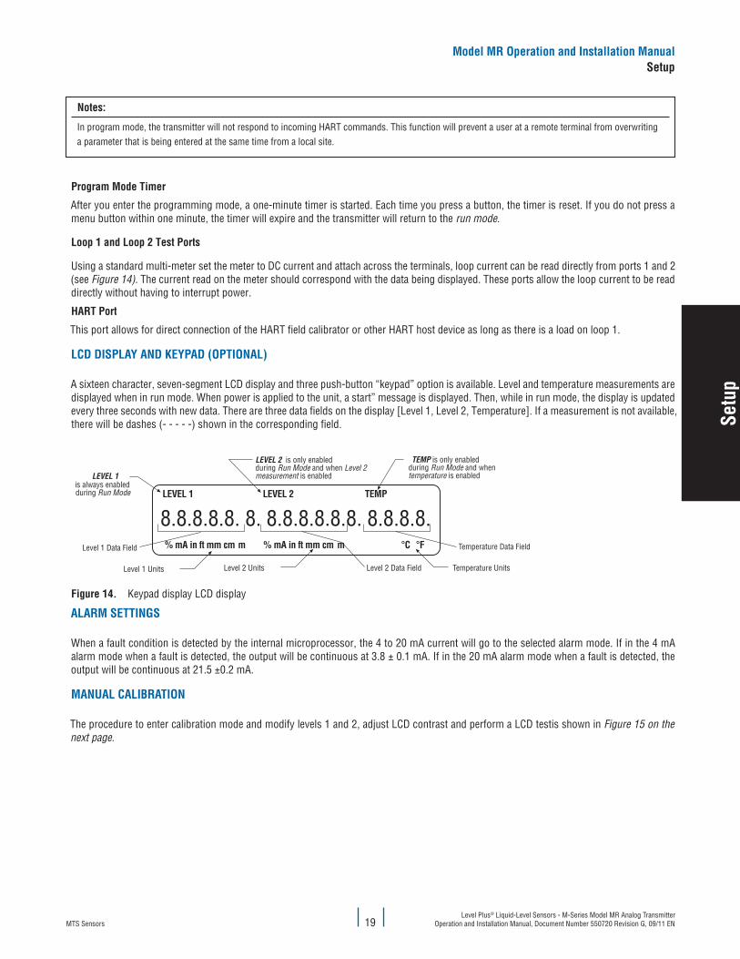
lcD DISPlay aND keyPaD (OPTIONal)
A sixteen character, seven-segment LCD display and three push-button “keypad” option is available. Level and temperature measurements are displayed when in run mode. When power is applied to the unit, a start” message is displayed. Then, while in run mode, the display is updated every three seconds with new data. There are three data fields on the display [Level 1, Level 2, Temperature]. If a measurement is not available, there will be dashes (- - - - -) shown in the corresponding field.
8.8.8.8.8. 8. 8.8.8.8.8.8. 8.8.8.8.% mA in ft mm cm m % mA in ft mm cm m °C °F
LEVEL 1 LEVEL 2 TEMP
Level 1 Data Field Temperature Data Field
Level 2 Data Field
LEVEL 1is always enabledduring Run Mode
LEVEL 2 is only enabledduring Run Mode and when Level 2 measurement is enabled
TEMP is only enabledduring Run Mode and whentemperature is enabled
Level 1 Units Level 2 Units Temperature Units
figure 14. Keypad display LCD display
alaRM SeTTINGS
When a fault condition is detected by the internal microprocessor, the 4 to 20 mA current will go to the selected alarm mode. If in the 4 mA alarm mode when a fault is detected, the output will be continuous at 3.8 ± 0.1 mA. If in the 20 mA alarm mode when a fault is detected, the output will be continuous at 21.5 ±0.2 mA.
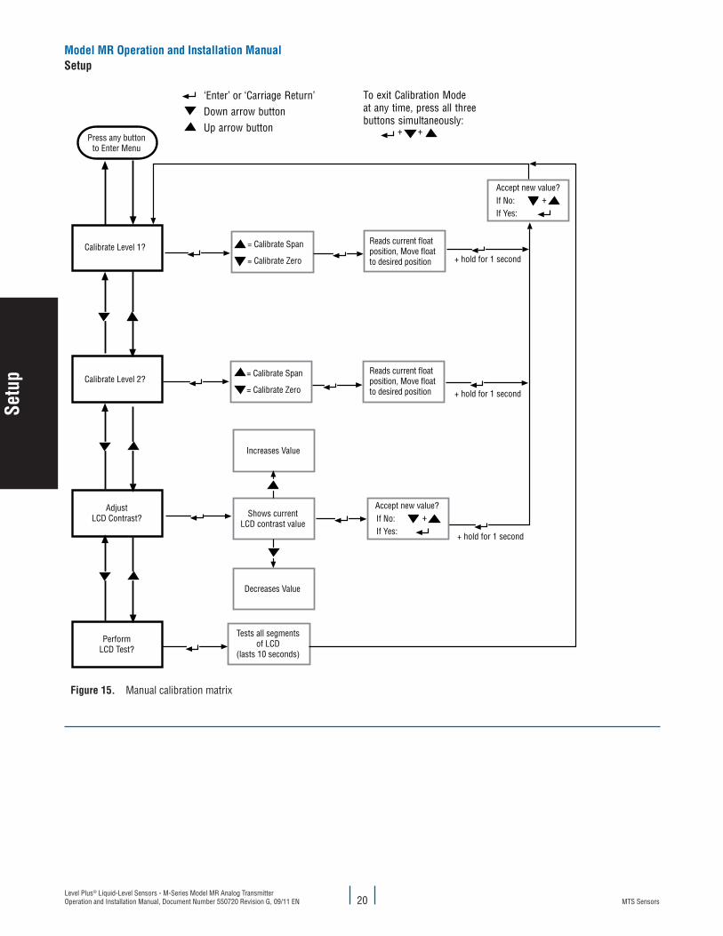
MaNual calIBRaTION
The procedure to enter calibration mode and modify levels 1 and 2, adjust LCD contrast and perform a LCD testis shown in Figure 15 on the next page.
Model MR Operation and Installation ManualSetup
MTS SensorsLevel Plus® Liquid-Level Sensors - M-Series Model MR Analog Transmitter Operation and Installation Manual, Document Number 550720 Revision G, 09/11 EN 20
Model MR Operation and Installation ManualSetup
Calibrate Level 1?
Calibrate Level 2?
AdjustLCD Contrast?
PerformLCD Test?
Press any buttonto Enter Menu
Accept new value?If No: +If Yes:
Reads current floatposition, Move floatto desired position
= Calibrate Span
= Calibrate Zero
= Calibrate Span
= Calibrate Zero
Increases Value
Decreases Value
Shows currentLCD contrast value
Accept new value?If No: +If Yes:
Tests all segmentsof LCD
(lasts 10 seconds)
+ +
+ hold for 1 second
To exit Calibration Modeat any time, press all threebuttons simultaneously:
‘Enter’ or ‘Carriage Return’Down arrow buttonUp arrow button
Reads current floatposition, Move floatto desired position + hold for 1 second
+ hold for 1 second
figure 15. Manual calibration matrix
Setu
p
MTS SensorsLevel Plus® Liquid-Level Sensors - M-Series Model MR Analog Transmitter
Operation and Installation Manual, Document Number 550720 Revision G, 09/11 EN21
Model MR Operation and Installation ManualSetup
Setup using haRT field communicator
Refer to the documentation that comes with the Rosemount Model 275 and 375 Field Communicator for specific sensor calibration informa-tion. This section describes how the HART protocol is applied to the Level Plus Model MR transmitter only.
Using the HART interface allows for calibration without having to remove the transmitter from the process and position of the floats. You can perform this function by using HART commands 35 and 65.
Any measured output may be assigned to any variable. Loop #1 is always the primary variable (PV); level 1 is usually assigned to loop 1. Loop 2 is always the Second Variable (SV); usually represents temperature or level 2. The Third Variable (TV) and Fourth Variable (FV) may be assigned to any remaining output such as, level 2, temperature. Analog output codes are 0, 1, and 2 respectively.
Calibration set points for level are given as the absolute displacement (in the appropriate units) from the tip of the sensor pipe. For example, if the Zero (LRV) position for level 1 is given as 5 inches, the transmitter will produce 4 mA when the float is 5 inches from the tip of the sensor pipe. If the Span (URV) position for level 1 is given as 30 inches, the transmitter will produce 20 mA when the float is 35 inches from the top of the sensor pipe. To calibrate the temperature set points, the Zero (LRV) and Span (URV) points are given in degrees. For temperature, the Zero (LRV) value (in degrees) must always be less than the Span (URV) value (in degrees).
PRePaRING The TRaNSMITTeR fOR Re-calIBRaTION
The Model MR transmitter can be re-calibrated by using the model 275 and 375 Field Communicator. Complete the following procedure to reset the zero and span values for loop 1 (only loop 1 can be calibrated with the HART Field Communicator using the generic XMTR type driver. To access both loops as well as other parameters, the MTS device driver must be purchased and installed in to the 275/375 field communicator. For more information about the HART device driver, go to HARTcomm.org.
attention:
DO NOT enter a high value that exceeds the active length of the sensor.
Before you begin, perform the following steps:1. Connect the transmitter to a clean 24 Vdc power supply. Use a linear supply, switching types do not provide ripple-free power. HART
cannot tolerate more than a 25 mV voltage ripple.2. If the unit is installed in a live application, place your automatic controllers in manual mode and be advised that the output current will
change during calibration.3. Follow safe working procedures for working on live equipment in a hazardous location before you remove the housing cover.4. Connect the HART Field Communicator to the terminals that are labeled HART located on the front panel display of the Level Plus
transmitter.5. Press the black and white I/O button on the HART terminal. The HART terminal will perform an automatic self test. The Main window
displays. If the device is not connected properly, the message “No device found” displays.6. In the Main window, press the key #1, the Device Setup window displays. 7. In the Device setup window, press key #3. The Basic Setup window displays.8. In the Basic Setup window, press key #3. The Range Values window displays.
SeTTING The lOW value
Complete the following steps to set the low value:1. To set the low value, Process Variable, Low Range Value (PV LRV) to 4 mA, select Key #1. The PV LRV window displays the current low
value. Below the highlighted value located under the current value, key in the low value you want (example 3.00 in. is shown; if 4 inches is the value you want, key in 4.) then, press Enter (F4) located below the LCD display.
2. To write the changed lower value to memory, press the Send key.3. Two Warning messages will display before the new values take affect; if your new low values are correct, respond to the Warning
messages by pressing OK when prompted. This action resets the Low Range Value, or 4 mA position into the transmitter’s memory.4. Go back to the Range Values window to verify that the new parameters have been accepted into the transmitter’s memory.5. Do one of the following:
5a. Exit program mode. 5b. To reset the upper value, continue with “Setting the Upper Range Value.
SeTTING The uPPeR RaNGe value
Complete the following steps to set the Upper Range Value:
Setu
p
MTS SensorsLevel Plus® Liquid-Level Sensors - M-Series Model MR Analog Transmitter Operation and Installation Manual, Document Number 550720 Revision G, 09/11 EN 22
caution:
DO NOT enter a high value that exceeds the active length of the sensor.
1. Open the Range Values window. To set the 20 mA Upper Range Value, press Key #2. The Process Variable, Upper Range Value (PV URV) window displays.
2. As shown the Lower Value window, the current value displays with a highlighted number below the value displayed. To change the upper value, key in the new value. You can use whole numbers or whole numbers and decimals (example, 40 = 40 inches, or 40.5 = 40.50 inches.) Whole numbers will be converted as decimal equivalents automatically by the HART terminal.
3. Key in the new Upper Range Value and press Enter or (F4). The Range Values window displays.4. Verify that the upper and lower values are correct. If the values are correct, press Send.5. You will be prompted with two Warning messages, press OK in response to both warnings.
Setup using MTS field Setup software
Adjustments to the calibration and setup parameters of the transmitter may be done using the MTS Field Setup Software and a RS232 to HART converter (SMAR HI-311, MTS Part # 380068). Be sure to install the latest software package, go to www.mtssensors.com for more information.
uSING The MTS fIelD SeTuP SOfTWaRe
Tools Required:
• HART adapter/converter• 24 Vdc power supply• PC
Complete the following steps to Install Setup Software1. Insert the software installation CD into computer or go to www.mtssensors.com and download the latest software.2. Open folder “Setup software Analog_Digital”3. Open folder “Analog”4. Open file “M-Series Field Setup”5. Follow on screen instructions
Complete the following steps to Install the hardware
1. Connect Power Supply to level transmitter2. Connect HART adapter to level transmitter and PC
attention:
Be sure loop #1 is connected to a load of 250 to 500 ohm. A transmitter installed in a control loop is a good example of the loop load. A 250 ohm load resistor may need to be added to the loop for HART to communicate effectively.
3. Turn on power4. Open Setup Software. Data should fill in. If no data appears select a different serial communication port.
Model MR Operation and Installation ManualSetup
Setu
p
MTS SensorsLevel Plus® Liquid-Level Sensors - M-Series Model MR Analog Transmitter
Operation and Installation Manual, Document Number 550720 Revision G, 09/11 EN23
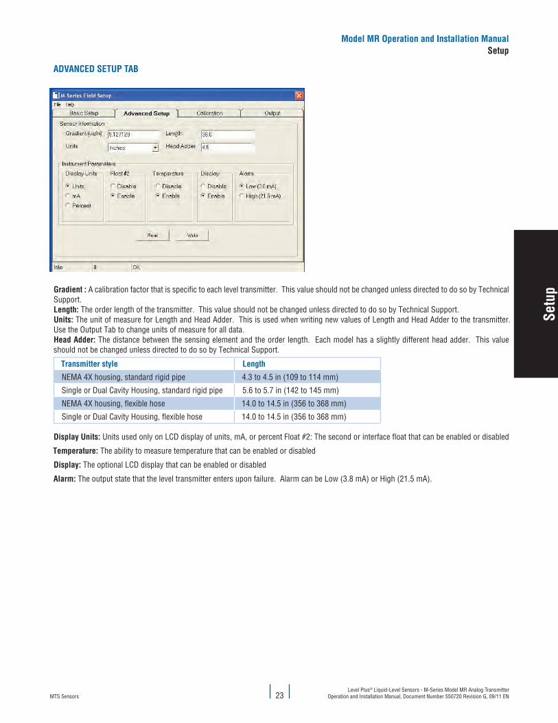
aDvaNceD SeTuP TaB
Gradient : A calibration factor that is specific to each level transmitter. This value should not be changed unless directed to do so by Technical Support.length: The order length of the transmitter. This value should not be changed unless directed to do so by Technical Support.units: The unit of measure for Length and Head Adder. This is used when writing new values of Length and Head Adder to the transmitter. Use the Output Tab to change units of measure for all data.head adder: The distance between the sensing element and the order length. Each model has a slightly different head adder. This value should not be changed unless directed to do so by Technical Support.
Transmitter style length
NEMA 4X housing, standard rigid pipe 4.3 to 4.5 in (109 to 114 mm)
Single or Dual Cavity Housing, standard rigid pipe 5.6 to 5.7 in (142 to 145 mm)
NEMA 4X housing, flexible hose 14.0 to 14.5 in (356 to 368 mm)
Single or Dual Cavity Housing, flexible hose 14.0 to 14.5 in (356 to 368 mm)
Display units: Units used only on LCD display of units, mA, or percent Float #2: The second or interface float that can be enabled or disabled
Temperature: The ability to measure temperature that can be enabled or disabled
Display: The optional LCD display that can be enabled or disabled
alarm: The output state that the level transmitter enters upon failure. Alarm can be Low (3.8 mA) or High (21.5 mA).
Model MR Operation and Installation ManualSetup
Setu
p
MTS SensorsLevel Plus® Liquid-Level Sensors - M-Series Model MR Analog Transmitter Operation and Installation Manual, Document Number 550720 Revision G, 09/11 EN 24
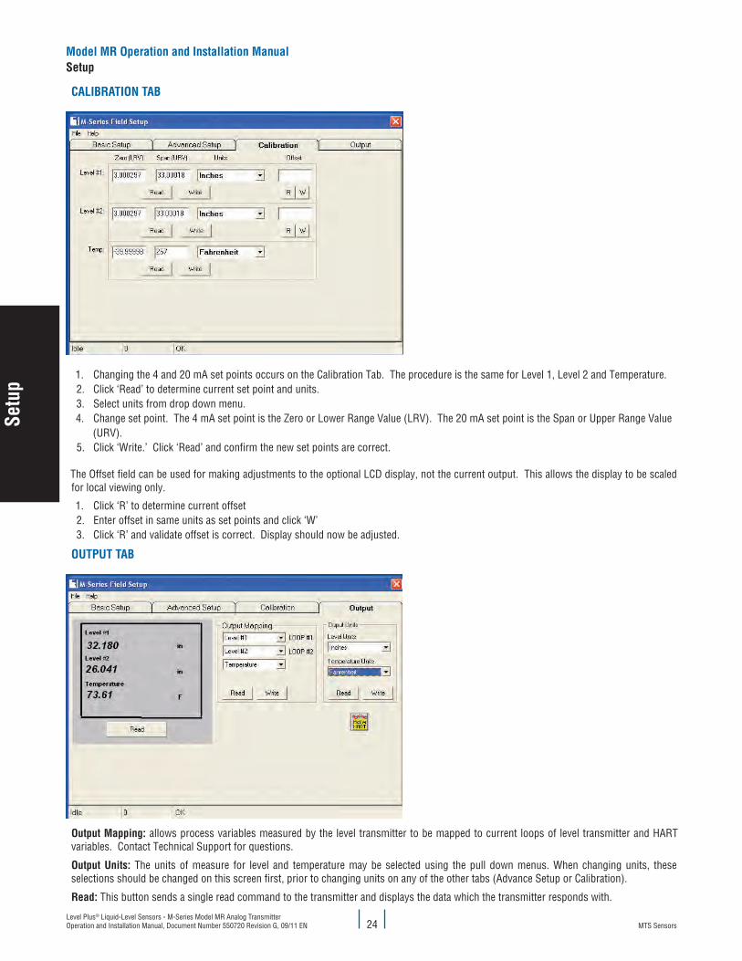
calIBRaTION TaB
1. Changing the 4 and 20 mA set points occurs on the Calibration Tab. The procedure is the same for Level 1, Level 2 and Temperature.2. Click ‘Read’ to determine current set point and units.3. Select units from drop down menu.4. Change set point. The 4 mA set point is the Zero or Lower Range Value (LRV). The 20 mA set point is the Span or Upper Range Value
(URV).5. Click ‘Write.’ Click ‘Read’ and confirm the new set points are correct.
The Offset field can be used for making adjustments to the optional LCD display, not the current output. This allows the display to be scaled for local viewing only.
1. Click ‘R’ to determine current offset2. Enter offset in same units as set points and click ‘W’3. Click ‘R’ and validate offset is correct. Display should now be adjusted.
OuTPuT TaB
Output Mapping: allows process variables measured by the level transmitter to be mapped to current loops of level transmitter and HART variables. Contact Technical Support for questions.
Output units: The units of measure for level and temperature may be selected using the pull down menus. When changing units, these selections should be changed on this screen first, prior to changing units on any of the other tabs (Advance Setup or Calibration).
Read: This button sends a single read command to the transmitter and displays the data which the transmitter responds with.
Model MR Operation and Installation ManualSetup
Setu
p
MTS SensorsLevel Plus® Liquid-Level Sensors - M-Series Model MR Analog Transmitter
Operation and Installation Manual, Document Number 550720 Revision G, 09/11 EN25
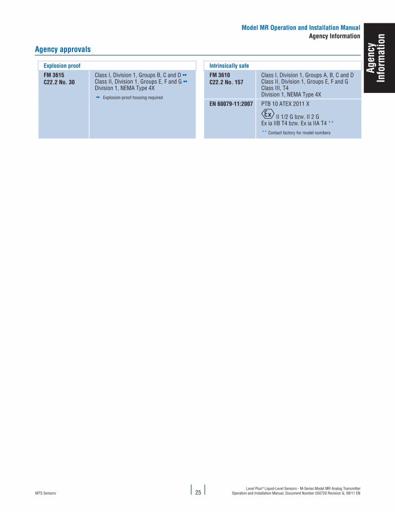
agency approvals
explosion proof Intrinsically safe
fM 3615c22.2 No. 30
Class I, Division 1, Groups B, C and D ••Class II, Division 1, Groups E, F and G ••Division 1, NEMA Type 4X
•• Explosion-proof housing required
fM 3610c22.2 No. 157
Class I, Division 1, Groups A, B, C and DClass II, Division 1, Groups E, F and GClass III, T4Division 1, NEMA Type 4X
eN 60079-11:2007 PTB 10 ATEX 2011 X
II 1/2 G bzw. II 2 GEx ia IIB T4 bzw. Ex ia IIA T4 **
** Contact factory for model numbers
Model MR Operation and Installation Manualagency Information
agen
cyIn
form
atio
n
MTS SensorsLevel Plus® Liquid-Level Sensors - M-Series Model MR Analog Transmitter Operation and Installation Manual, Document Number 550720 Revision G, 09/11 EN 26
Model MR Operation and Installation Manualagency Information
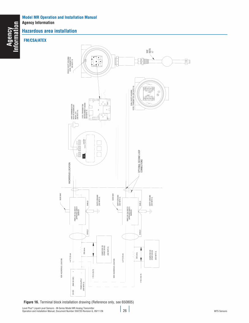
hazardous area installation
fM/cSa/aTeX
figure 16. Terminal block installation drawing (Reference only, see 650805)
agen
cyIn
form
atio
n
MTS SensorsLevel Plus® Liquid-Level Sensors - M-Series Model MR Analog Transmitter
Operation and Installation Manual, Document Number 550720 Revision G, 09/11 EN27
Model MR Operation and Installation Manualagency Information
agen
cyIn
form
atio
n
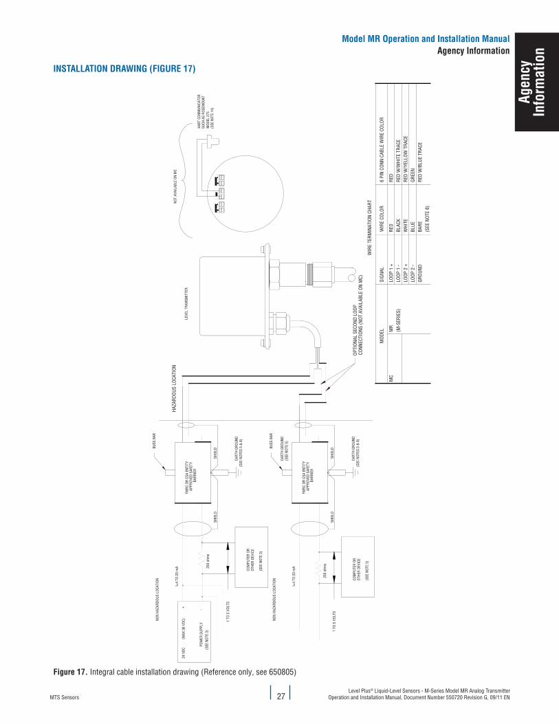
INSTallaTION DRaWING (fIGuRe 17)
figure 17. Integral cable installation drawing (Reference only, see 650805)
MTS SensorsLevel Plus® Liquid-Level Sensors - M-Series Model MR Analog Transmitter Operation and Installation Manual, Document Number 550720 Revision G, 09/11 EN 28
Model MR Operation and Installation Manualagency Information
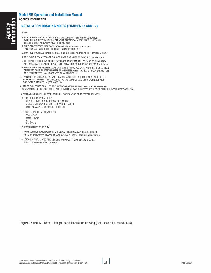
INSTallaTION DRaWING NOTeS (fIGuReS 16 aND 17)
AND CLASS HAZARDOUS LOCATIONS.14. USE ONLY NRTL LISTED AND CSA CERTIFIED DUST-TIGHT SEAL FOR CLASS
ONLY BE CONNECTED IN ACCORDANCE W/MFG IS INSTALLATION INSTRUCTIONS.
13. HART COMMUNICATOR WHICH FM & CSA APPROVED (AS APPLICABLE) MUST
CLASS IIICLASS , DIVISION 1, GROUPS E, F AND G,
11. EACH LOOP ENTITY PARAMETERS
WITH NEMA/TYPE 4X, FOR OUTDOOR USE.
Vmax= 36VImax= 118mAC = 0L = 200uH
WITH THE COUNTRY IN USE (eg CANADIAN ELECTRICAL CODE, PART 1, NATIONAL
NOT EXCEED BARRIER La. (SEE NOTE 14) BARRIER Ca. TRANSMITTER Li PLUS TOTAL CABLE INDUCTANCE FOR EACH LOOP MUST
7. TRANSMITTER Ci PLUS TOTAL CABLE CAPACITANCE FOR EACH LOOP MUST NOT EXCEED
AND TRANSMITTER Imax IS GREATER THAN BARRIER Isc. APPROVED CONFIGURATION WHERE TRANSMITTER Vmax IS GREATER THAN BARRIER Voc
6. SAFETY BARRIERS ARE FMRC AND CSA ENTITY APPROVED SAFETY BARRIERS USED IN AN
4. FOR FMRC & CSA APPROVED GAUGES, BARRIERS MUST BE FMRC & CSA APPROVED.
8. GAUGE ENCLOSURE SHALL BE GROUNDED TO EARTH GROUND THROUGH THE PROVIDED
APPROVED SAFETY BARRIERS AND SYSTEM EARTH GROUND MUST BE LESS THAN 1 ohm.5. THE CONNECTION BETWEEN THE EARTH GROUND TERMINAL
3. CONTROL ROOM EQUIPMENT SHOULD NOT USE OR GENERATE MORE THAN 250 V RMS.
1. FOR I.S. FIELD INSTALLATION WIRING SHALL BE INSTALLED IN ACCORDANCE
10CLASS I, DIVISION 1, GROUPS A, B, C AND DINTRINSICIALLY SAFE FOR:
9. NO REVISIONS SHALL BE MADE WITHOUT
GROUND LUG IN THE ENCLOSURE. WHERE INTEGRAL CABLE IS PROVIDED, LOOP 2 SHIELD IS INSTRUMENT GROUND.
CABLE CAPACITANCE SHALL BE LESS THAN 30 PF PER FOOT.
.
2. SHIELDED TWISTED CABLE OF 24 AWG OR HEAVIER SHOULD BE USED.
NOTES:
OF FMRC OR CSA ENTITY
NOTIFICATION OF APPROVAL AGENCY(S).
12. TEMPERATURE CODE IS T4.
ELECTRIC CODE ANSI/NFPA 70 ARTICLE 504-30.)
figure 16 and 17 - Notes - Integral cable installation drawing (Reference only, see 650805)
agen
cyIn
form
atio
n
MTS SensorsLevel Plus® Liquid-Level Sensors - M-Series Model MR Analog Transmitter
Operation and Installation Manual, Document Number 550720 Revision G, 09/11 EN29
Model MR Operation and Installation Manualagency Information
agen
cyIn
form
atio
n
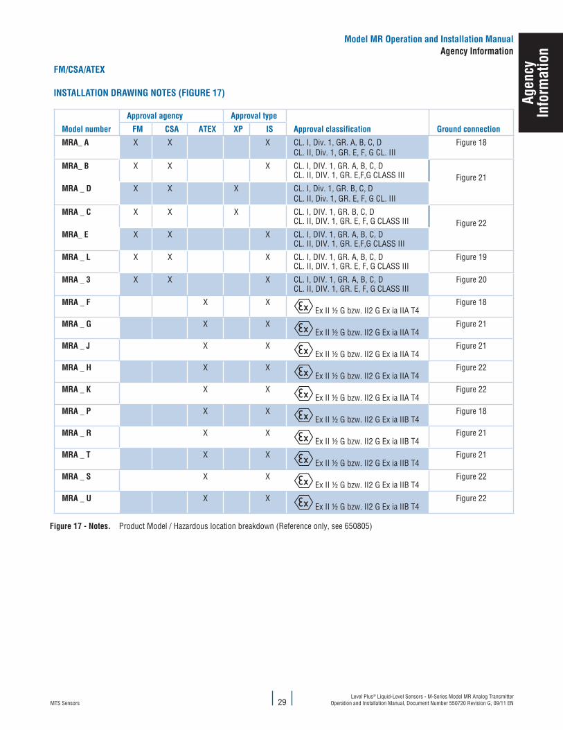
fM/cSa/aTeX
INSTallaTION DRaWING NOTeS (fIGuRe 17)
Model number
approval agency approval type
approval classification Ground connection fM cSa aTeX XP IS
MRa_ a X X X CL. I, Div. 1, GR. A, B, C, DCL. II, Div. 1, GR. E, F, G CL. III
Figure 18
MRa_ B X X X CL. I, DIV. 1, GR. A, B, C, DCL. II, DIV. 1, GR. E,F,G CLASS III Figure 21
MRa _ D X X X CL. I, Div. 1, GR. B, C, DCL. II, Div. 1, GR. E, F, G CL. III
MRa _ c X X X CL. I, DIV. 1, GR. B, C, DCL. II, DIV. 1, GR. E, F, G CLASS III Figure 22
MRa_ e X X X CL. I, DIV. 1, GR. A, B, C, DCL. II, DIV. 1, GR. E,F,G CLASS III
MRa _ l X X X CL. I, DIV. 1, GR. A, B, C, DCL. II, DIV. 1, GR. E, F, G CLASS III
Figure 19
MRa _ 3 X X X CL. I, DIV. 1, GR. A, B, C, DCL. II, DIV. 1, GR. E, F, G CLASS III
Figure 20
MRa _ f X X Ex II ½ G bzw. II2 G Ex ia IIA T4
Figure 18
MRa _ G X X Ex II ½ G bzw. II2 G Ex ia IIA T4
Figure 21
MRa _ J X X Ex II ½ G bzw. II2 G Ex ia IIA T4
Figure 21
MRa _ h X X Ex II ½ G bzw. II2 G Ex ia IIA T4
Figure 22
MRa _ k X X Ex II ½ G bzw. II2 G Ex ia IIA T4
Figure 22
MRa _ P X X Ex II ½ G bzw. II2 G Ex ia IIB T4
Figure 18
MRa _ R X X Ex II ½ G bzw. II2 G Ex ia IIB T4
Figure 21
MRa _ T X X Ex II ½ G bzw. II2 G Ex ia IIB T4
Figure 21
MRa _ S X X Ex II ½ G bzw. II2 G Ex ia IIB T4
Figure 22
MRa _ u X X Ex II ½ G bzw. II2 G Ex ia IIB T4
Figure 22
figure 17 - Notes. Product Model / Hazardous location breakdown (Reference only, see 650805)
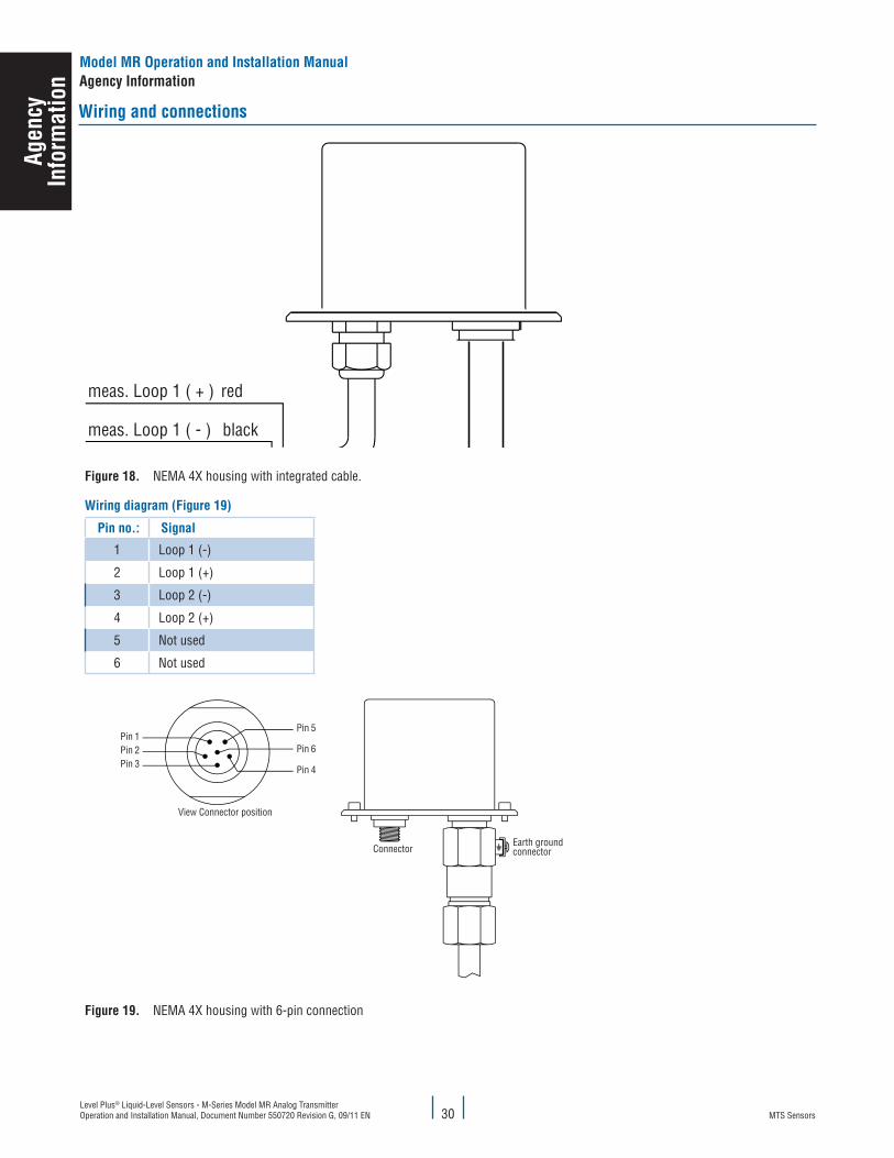
MTS SensorsLevel Plus® Liquid-Level Sensors - M-Series Model MR Analog Transmitter Operation and Installation Manual, Document Number 550720 Revision G, 09/11 EN 30
Model MR Operation and Installation Manualagency Information
agen
cyIn
form
atio
n
Wiring and connections
figure 18. NEMA 4X housing with integrated cable.
Wiring diagram (figure 19)
Pin no.: Signal
1 Loop 1 (-)
2 Loop 1 (+)
3 Loop 2 (-)
4 Loop 2 (+)
5 Not used
6 Not used
figure 19. NEMA 4X housing with 6-pin connection
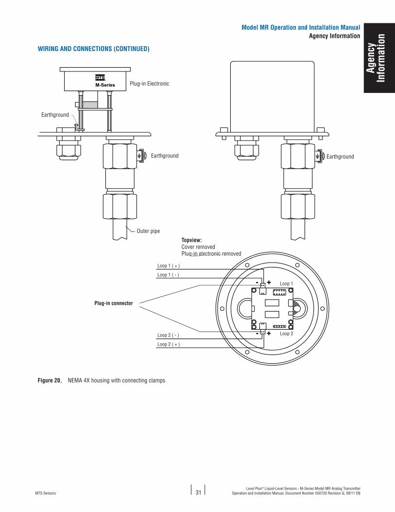
MTS SensorsLevel Plus® Liquid-Level Sensors - M-Series Model MR Analog Transmitter
Operation and Installation Manual, Document Number 550720 Revision G, 09/11 EN31
Model MR Operation and Installation Manualagency Information
WIRING aND cONNecTIONS (cONTINueD)
figure 20. NEMA 4X housing with connecting clampsag
ency
Info
rmat
ion
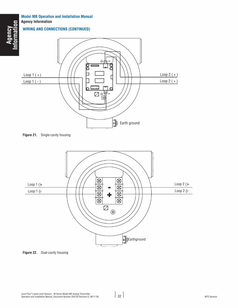
MTS SensorsLevel Plus® Liquid-Level Sensors - M-Series Model MR Analog Transmitter Operation and Installation Manual, Document Number 550720 Revision G, 09/11 EN 32
WIRING aND cONNecTIONS (cONTINueD)
figure 21. Single-cavity housing
figure 22. Dual-cavity housing
Model MR Operation and Installation Manualagency Information
agen
cyIn
form
atio
n
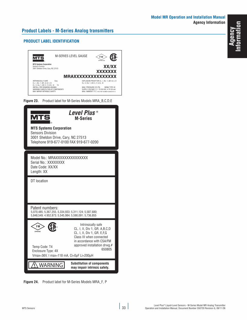
MTS SensorsLevel Plus® Liquid-Level Sensors - M-Series Model MR Analog Transmitter
Operation and Installation Manual, Document Number 550720 Revision G, 09/11 EN33
Model MR Operation and Installation Manualagency Information
Product labels - M-Series analog transmitters
PRODucT laBel IDeNTIfIcaTION
FMAPPROVED
MTS Systems CorporationSensors Division3001 Sheldon Drive, Cary, NC 27513
®
XX/XXXXXXXXX
MRAXXXXXXXXXXXXXXXEXPLOSION PROOF FOR CL. I, Div. 1, GR. B, C, DCL. II, Div. 1, GR. E, F, G CL. III
MAX. PRESSURE 275 PSI NEMA TYPE 4XSUPPLY VOLTAGE 11.1 TO 36 VDC, 4 TO 20 mAMAX. AMBIENT 71˚C MTS PART NUMBER 550685 REV A
INTRINSICALLY SAFE ExiaCL. I, Div. 1, GR. A, B, C, D:CL. II, Div. 1, GR. E, F, G CL. III T4INSTALL PER DRAWING #650805WARNING SUBSITUTION OF COMPONENTSMAY IMPAIR INTRINSIC SAFETY.
M-SERIES LEVEL GAUGE
figure 23. Product label for M-Series Models MRA_B,C,D,E
Vmax=36V, I max=118 mA, Ci=0μF Li=200μH
Intrinsically safeCL. I, II, Div 1, GR. A,B,C,DCL. I, II, Div 1, GR. E,F,GClass III when connectedin accordance with CSA/FMapproved installation drwg.# 650805
figure 24. Product label for M-Series Models MRA_F, P
agen
cyIn
form
atio
n
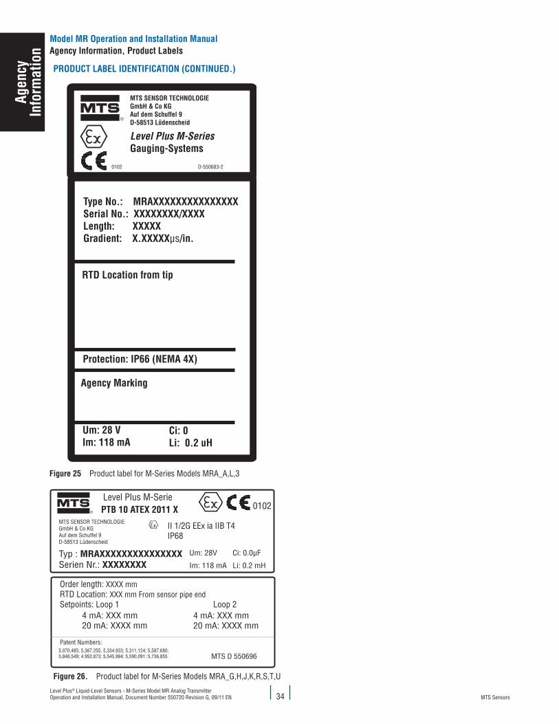
MTS SensorsLevel Plus® Liquid-Level Sensors - M-Series Model MR Analog Transmitter Operation and Installation Manual, Document Number 550720 Revision G, 09/11 EN
PRODucT laBel IDeNTIfIcaTION (cONTINueD.)
®
Um: 28 V Im: 118 mA
Ci: 0 Li: 0.2 uH
0102 D-550683-2
MTS SENSOR TECHNOLOGIEGmbH & Co KGAuf dem Schuffel 9D-58513 Lüdenscheid
Level Plus M-SeriesGauging-Systems
Type No.: MRAXXXXXXXXXXXXXXXSerial No.: XXXXXXXX/XXXX Length: XXXXXGradient: X.XXXXXμs/in.
RTD Location from tip
Protection: IP66 (NEMA 4X)
Agency Marking
figure 25 Product label for M-Series Models MRA_A,L,3
®
Typ : MRAXXXXXXXXXXXXXXXSerien Nr.: XXXXXXXX
Um: 28V
Im: 118 mA
Ci: 0.0μF
Li: 0.2 mH
Level Plus M-SeriePTB 10 ATEX 2011 X 0102
FMAPPROVED
MTS Systems CorporationSensors Division3001 Sheldon Drive, Cary, NC 27513
®
EXPLOSION PROOF FOR CL. I, Div. 1, GR. B, C, DCL. II, Div. 1, GR. E, F, G CL. III
MAX. PRESSURE 275 PSI NEMA TYPE 4XSUPPLY VOLTAGE 11.1 TO 36 VDC, 4 TO 20 mAMAX. AMBIENT 71˚C MTS PART NUMBER 550696 REV A
INTRINSICALLY SAFE EXITCL. I, Div. 1, GR. A, B, C, D:CL. II, Div. 1, GR. E, F, G CL. III T4INSTALL PER DRAWING #650805WARNING SUBSITUTION OF COMPONENTSMAY IMPAIR INTRINSIC SAFETY.
XX/XXXXXXXXX
MRAXXXXXXXXXXXXXXX
M-SERIES LEVEL GAUGE
4 mA: XXX mm 20 mA: XXXX mm
Order length: XXXX mmRTD Location: XXX mm From sensor pipe endSetpoints: Loop 1 Loop 2
Patent Numbers:
MTS SENSOR TECHNOLOGIEGmbH & Co KGAuf dem Schuffel 9D-58513 Lüdenscheid
II 1/2G EEx ia IIB T4IP68
4 mA: XXX mm20 mA: XXXX mm
MTS D 550696
figure 26. Product label for M-Series Models MRA_G,H,J,K,R,S,T,U
34
Model MR Operation and Installation Manualagency Information, Product labels
agen
cyIn
form
atio
n

MTS SensorsLevel Plus® Liquid-Level Sensors - M-Series Model MR Analog Transmitter
Operation and Installation Manual, Document Number 550720 Revision G, 09/11 EN35
agency certifications
aTeX aPPROval
agen
cyIn
form
atio
n
Model MR Operation and Installation Manualagency Information

MTS SensorsLevel Plus® Liquid-Level Sensors - M-Series Model MR Analog Transmitter Operation and Installation Manual, Document Number 550720 Revision G, 09/11 EN 36
aTeX aPPROval
Model MR Operation and Installation Manualagency Information, Product labels
agen
cyIn
form
atio
n
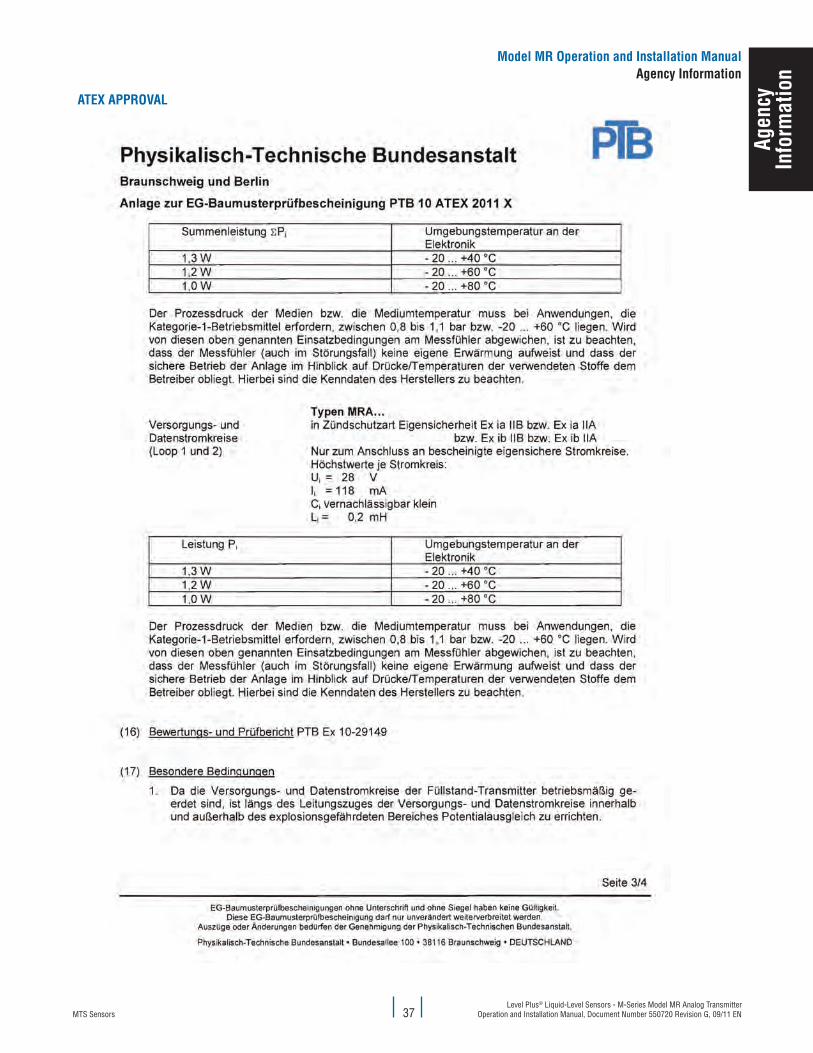
MTS SensorsLevel Plus® Liquid-Level Sensors - M-Series Model MR Analog Transmitter
Operation and Installation Manual, Document Number 550720 Revision G, 09/11 EN
aTeX aPPROval
37
Model MR Operation and Installation Manualagency Information
agen
cyIn
form
atio
n

MTS SensorsLevel Plus® Liquid-Level Sensors - M-Series Model MR Analog Transmitter Operation and Installation Manual, Document Number 550720 Revision G, 09/11 EN 38
Model MR Operation and Installation Manualagency Information
aTeX aPPROval
agen
cyIn
form
atio
n
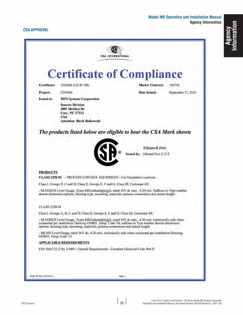
MTS SensorsLevel Plus® Liquid-Level Sensors - M-Series Model MR Analog Transmitter
Operation and Installation Manual, Document Number 550720 Revision G, 09/11 EN39
Model MR Operation and Installation Manualagency Information
agen
cyIn
form
atio
n
cSa aPPROval
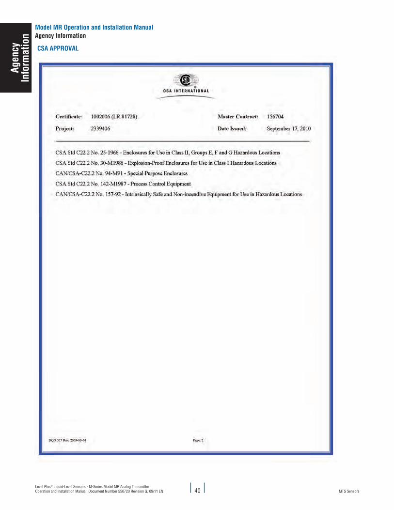
MTS SensorsLevel Plus® Liquid-Level Sensors - M-Series Model MR Analog Transmitter Operation and Installation Manual, Document Number 550720 Revision G, 09/11 EN
Model MR Operation and Installation Manualagency Information
40
agen
cyIn
form
atio
n
cSa aPPROval

MTS SensorsLevel Plus® Liquid-Level Sensors - M-Series Model MR Analog Transmitter
Operation and Installation Manual, Document Number 550720 Revision G, 09/11 EN
Model MR Operation and Installation Manualagency Information
41
agen
cyIn
form
atio
n
fM aPPROval
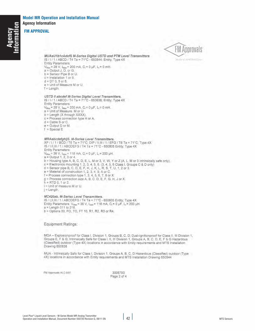
MTS SensorsLevel Plus® Liquid-Level Sensors - M-Series Model MR Analog Transmitter Operation and Installation Manual, Document Number 550720 Revision G, 09/11 EN 42
Model MR Operation and Installation Manualagency Information
agen
cyIn
form
atio
n
fM aPPROval
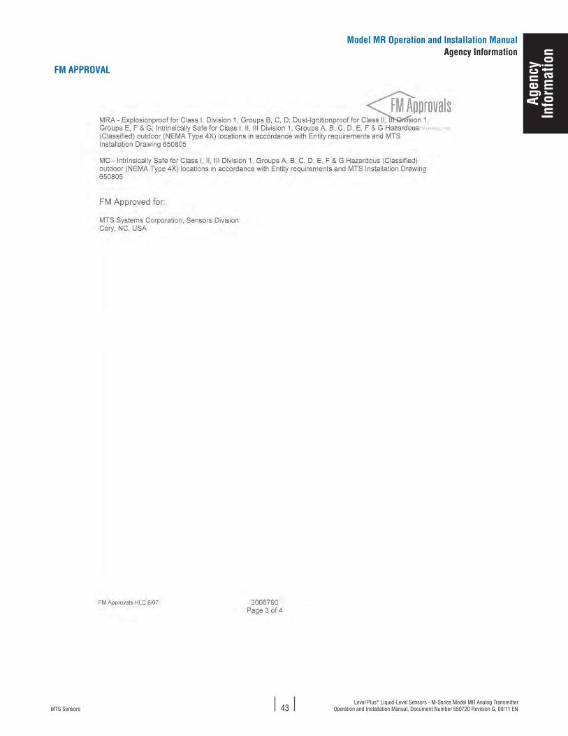
MTS SensorsLevel Plus® Liquid-Level Sensors - M-Series Model MR Analog Transmitter
Operation and Installation Manual, Document Number 550720 Revision G, 09/11 EN43
Model MR Operation and Installation Manualagency Information
agen
cyIn
form
atio
n
fM aPPROval
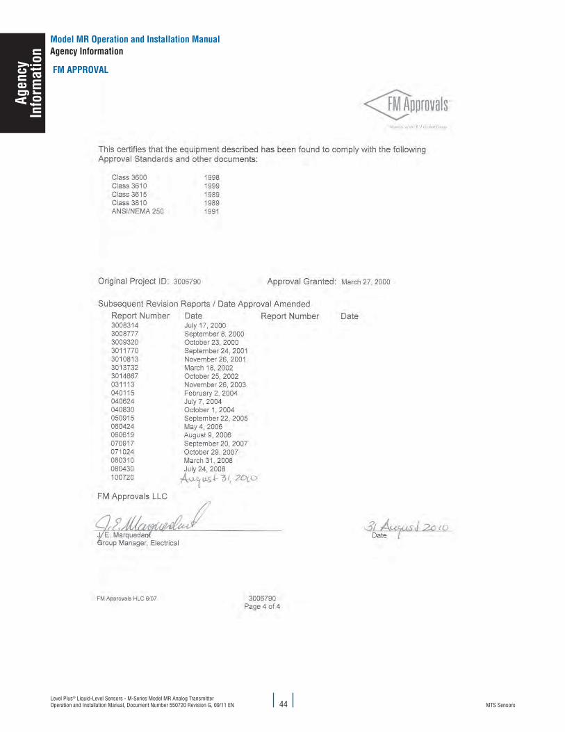
MTS SensorsLevel Plus® Liquid-Level Sensors - M-Series Model MR Analog Transmitter Operation and Installation Manual, Document Number 550720 Revision G, 09/11 EN 44
Model MR Operation and Installation Manualagency Information
agen
cyIn
form
atio
n
fM aPPROval

MTS SensorsLevel Plus® Liquid-Level Sensors - M-Series Model MR Analog Transmitter
Operation and Installation Manual, Document Number 550720 Revision G, 09/11 EN45
MTS, Temposonics and Level Plus are registered trademarks of MTS Systems Corporation. All other trademarks are the property of their respective owners. Printed in USA. Copyright © 2012 MTS Systems Corporation. All Rights Reserved in all media.
All specifications are subject to change. Contact MTS for specifications and engineering drawings that are critical to your application. Drawings contained in this document are for reference only. Go to http://www.mtssensors.com for the latest product information.awings contained in this document are for
reference only. Go to http://www.mtssensors.com for the latest product informatio
Document Part Number: 550720 Revision G, 09/11, 04/12 eN
MTS Sensor TechnologieGmbh & co. kG
Auf dem Schüffel 9D - 58513 Lüdenscheid, GermanyTel.: +49-2351-9587-0Fax: +49-2351-56491
e-mail: [email protected]://www.mtssensor.de
MTS Systems corporationSensors Division
3001 Sheldon DriveCary, North Carolina,27513, USATel.: +1-800-633-7609Fax: +1-919-677-2343
+1-800-498-4442 e-mail: [email protected]://www.mtssensors.com
SENSORS
®
MTS Sensors Technologycorporation
737 Aihara-cho, Machida-shiTokyo 194-0211, JapanTel.: +81-42-775-3838Fax: +81-42-775-5516
e-mail: [email protected]://www.mtssensor.co.jp