Embed Size (px)
Citation preview
Geneva, 02.01.2012 1
FORMATION STAGE 2006-2007 « Sciences de la Matière » WELSING, Roman École Normale Supérieure de Lyon Erasmus, Master 1 Université Claude Bernard Lyon1 Option Physique
__________________________________
LHCb Muon Chamber Alignment
__________________________________
Abstract The LHCb experiment at the Large Hadron Collider is designed to search for new physics namely by studying decays of mesons containing a bottom quark. In this report we will review the critical double role of the muon system, an LHCb component providing a high-pT trigger as well as identifying muons. We will then discuss why the alignment of each single multi-wire proportional muon chamber is important and therefore we evolve a strategy for the hardware alignment of the LHCb muon system.
Keywords: alignment, b-physics, LHCb, muon, MWPC Summer Studentship at
CERN LHCb Secretariat
1211-CH Geneva 23 Switzerland
Tel. +41-22-7673994 http://lhcb-public.web.cern.ch/lhcb-public/
http://www.cern.ch/
Supervisor Katharina Mair (Tel. -76162477, [email protected])
Co-Supervisor Burkhard Schmidt (Tel. -76162985, [email protected])

Geneva, 02.01.2012 2
Acknowledgements to Katharina Mair, Thomas Schneider, Burkhard Schmidt, the LHCb Collaboration, CERN and all 2007 Summer Students
Geneva, 02.01.2012 3
Table of contents LHCb Muon Chamber Alignment
Introduction 4 CERN and the LHC Project
I. Overview 5 II. The Large Hadron Collider 5 III. Physical Motivations 6 IV. Experimental Challenge 7 V. LHC Detectors 7 LHCb Detector and Muon System
VI. The LHCb Layout 8 VII. The LHCb Muon System 9 VIII. Setup and Installation 10 The Project
IX. Hardware Alignment 12 X. Alignment Work
13
X.1 Chamber coordinates 13 X.2 Perpendicular and wall alignment 14 X.3 Getting started 14 X.4 A first problem 15 X.5 The inner part 15 X.6 The intermediate part 15 X.7 The outer part 16 X.8 Cross-check with data 16 XI. Problematic points
17
XII. The final procedure 17 XIII. Some results 18 Conclusions
20
References 20
8911
Geneva, 02.01.2012 4
Introduction
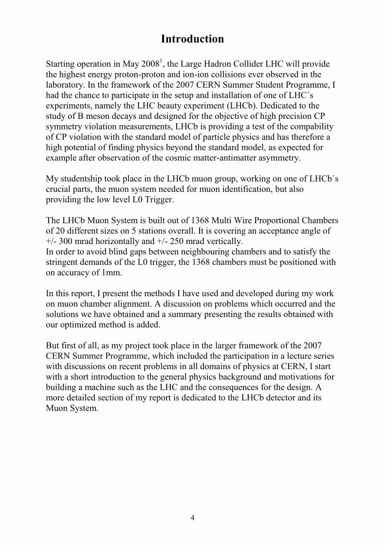
Starting operation in May 20081, the Large Hadron Collider LHC will provide the highest energy proton-proton and ion-ion collisions ever observed in the laboratory. In the framework of the 2007 CERN Summer Student Programme, I had the chance to participate in the setup and installation of one of LHC´s experiments, namely the LHC beauty experiment (LHCb). Dedicated to the study of B meson decays and designed for the objective of high precision CP symmetry violation measurements, LHCb is providing a test of the compability of CP violation with the standard model of particle physics and has therefore a high potential of finding physics beyond the standard model, as expected for example after observation of the cosmic matter-antimatter asymmetry. My studentship took place in the LHCb muon group, working on one of LHCb´s crucial parts, the muon system needed for muon identification, but also providing the low level L0 Trigger. The LHCb Muon System is built out of 1368 Multi Wire Proportional Chambers of 20 different sizes on 5 stations overall. It is covering an acceptance angle of +/- 300 mrad horizontally and +/- 250 mrad vertically. In order to avoid blind gaps between neighbouring chambers and to satisfy the stringent demands of the L0 trigger, the 1368 chambers must be positioned with on accuracy of 1mm. In this report, I present the methods I have used and developed during my work on muon chamber alignment. A discussion on problems which occurred and the solutions we have obtained and a summary presenting the results obtained with our optimized method is added. But first of all, as my project took place in the larger framework of the 2007 CERN Summer Programme, which included the participation in a lecture series with discussions on recent problems in all domains of physics at CERN, I start with a short introduction to the general physics background and motivations for building a machine such as the LHC and the consequences for the design. A more detailed section of my report is dedicated to the LHCb detector and its Muon System.
Geneva, 02.01.2012 5
‘Where the web was born’
CERN And the LHC project
Chapter I – Overview
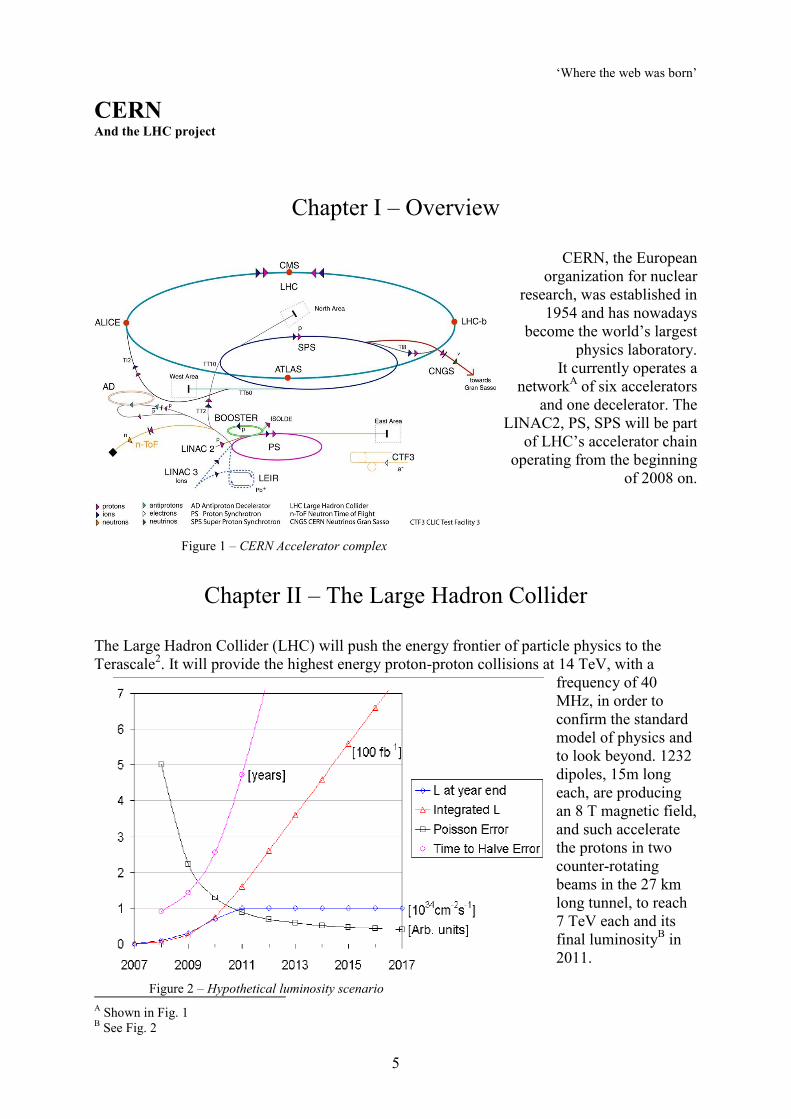
CERN, the European
organization for nuclear research, was established in
1954 and has nowadays become the world’s largest
physics laboratory. It currently operates a
networkA of six accelerators and one decelerator. The
LINAC2, PS, SPS will be part of LHC’s accelerator chain
operating from the beginning of 2008 on.
Chapter II – The Large Hadron Collider
The Large Hadron Collider (LHC) will push the energy frontier of particle physics to the Terascale2. It will provide the highest energy proton-proton collisions at 14 TeV, with a
frequency of 40 MHz, in order to confirm the standard model of physics and to look beyond. 1232 dipoles, 15m long each, are producing an 8 T magnetic field, and such accelerate the protons in two counter-rotating beams in the 27 km long tunnel, to reach 7 TeV each and its final luminosityB in 2011.
A Shown in Fig. 1 B See Fig. 2
Figure 1 – CERN Accelerator complex
Figure 2 – Hypothetical luminosity scenario
Geneva, 02.01.2012 6
Chapter III - Physical Motivations
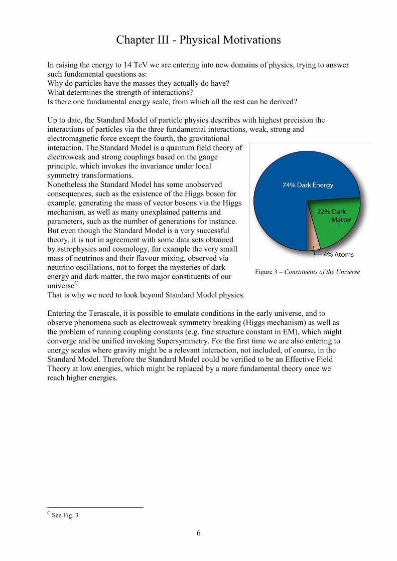
In raising the energy to 14 TeV we are entering into new domains of physics, trying to answer such fundamental questions as: Why do particles have the masses they actually do have? What determines the strength of interactions? Is there one fundamental energy scale, from which all the rest can be derived? Up to date, the Standard Model of particle physics describes with highest precision the interactions of particles via the three fundamental interactions, weak, strong and electromagnetic force except the fourth, the gravitational interaction. The Standard Model is a quantum field theory of electroweak and strong couplings based on the gauge principle, which invokes the invariance under local symmetry transformations. Nonetheless the Standard Model has some unobserved consequences, such as the existence of the Higgs boson for example, generating the mass of vector bosons via the Higgs mechanism, as well as many unexplained patterns and parameters, such as the number of generations for instance. But even though the Standard Model is a very successful theory, it is not in agreement with some data sets obtained by astrophysics and cosmology, for example the very small mass of neutrinos and their flavour mixing, observed via neutrino oscillations, not to forget the mysteries of dark energy and dark matter, the two major constituents of our universeC. That is why we need to look beyond Standard Model physics. Entering the Terascale, it is possible to emulate conditions in the early universe, and to observe phenomena such as electroweak symmetry breaking (Higgs mechanism) as well as the problem of running coupling constants (e.g. fine structure constant in EM), which might converge and be unified invoking Supersymmetry. For the first time we are also entering to energy scales where gravity might be a relevant interaction, not included, of course, in the Standard Model. Therefore the Standard Model could be verified to be an Effective Field Theory at low energies, which might be replaced by a more fundamental theory once we reach higher energies.
C See Fig. 3
Figure 3 – Constituents of the Universe
Geneva, 02.01.2012 7
Chapter IV - Experimental Challenges In order to solve these physical problems we are also facing technological challenges, for example material innovations to reach the magnetic fields necessary, which we do with superconducting magnets, as well as radiation resistance, or the high numbers of superposed events and tracks we need to identify. The protons interacting in the LHC are not elementary particles, but they do have a substructure. This leads to the fact that there are up to 1000 tracks3 streaming into the detector for each bunch crossing, with an average of 20 superposed events. Contrary to Electron-Positron colliders, a machine with higher precision but higher synchrotron radiation, hadronic jet production occurs. This is why the LHC is also called a discovery machine. We therefore distinguish soft, so called long-distance interactions between protons, and short-distance interactions between the proton’s point-like constituents, the quarks. Soft proton collisions, so called minimum bias events, have a dominating cross-section, whereas only in hard scattering there is a significant momentum transfer leading to a high transversal momentum, and consequently an interesting event. Seen the number of events occurring we need to avoid so called pile-up, which means the overlap in the readout between previously occupied detector channels and later physically relevant events. Therefore we need a high detector granularity and a fast read-out chain.
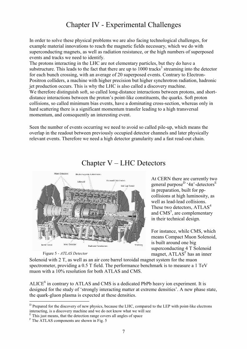
Chapter V – LHC Detectors At CERN there are currently two general purposeD ‘4π’-detectorsE in preparation, built for pp-collisions at high luminosity, as well as lead-lead collisions. These two detectors, ATLAS4 and CMS5, are complementary in their technical design. For instance, while CMS, which means Compact Muon Solenoid, is built around one big superconducting 4 T Solenoid magnet, ATLASF has an inner
Solenoid with 2 T, as well as an air core barrel toroidal magnet system for the muon spectrometer, providing a 0.5 T field. The performance benchmark is to measure a 1 TeV muon with a 10% resolution for both ATLAS and CMS. ALICE6 in contrary to ATLAS and CMS is a dedicated PbPb heavy ion experiment. It is designed for the study of ‘strongly interacting matter at extreme densities’. A new phase state, the quark-gluon plasma is expected at these densities. D Prepared for the discovery of new physics, because the LHC, compared to the LEP with point-like electrons interacting, is a discovery machine and we do not know what we will see E This just means, that the detection range covers all angles of space F The ATLAS components are shown in Fig. 5
Figure 5 - ATLAS Detector
Geneva, 02.01.2012 8
‘Three quarks for Muster Mark’
LHCb Detector and Muon System
Chapter VI – The LHCb Layout
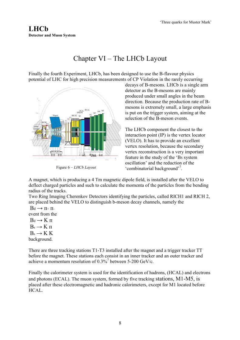
Finally the fourth Experiment, LHCb, has been designed to use the B-flavour physics potential of LHC for high precision measurements of CP Violation in the rarely occurring
decays of B-mesons. LHCb is a single arm detector as the B-mesons are mainly produced under small angles in the beam direction. Because the production rate of B-mesons is extremely small, a large emphasis is put on the trigger system, aiming at the selection of the B-meson events. The LHCb component the closest to the interaction point (IP) is the vertex locator (VELO). It has to provide an excellent vertex resolution, because the secondary vertex reconstruction is a very important feature in the study of the ‘BS system oscillation’ and the reduction of the ‘combinatorial background’7.
A magnet, which is producing a 4 Tm magnetic dipole field, is installed after the VELO to deflect charged particles and such to calculate the momenta of the particles from the bending radius of the tracks. Two Ring Imaging Cherenkov Detectors identifying the particles, called RICH1 and RICH 2, are placed behind the VELO to distinguish b-meson decay channels, namely the Bd → п+ п- event from the Bd → K п Bs → K п Bs → K K background. There are three tracking stations T1-T3 installed after the magnet and a trigger tracker TT before the magnet. These stations each consist in an inner tracker and an outer tracker and achieve a momentum resolution of 0.3%7 between 5-200 GeV/c. Finally the calorimeter system is used for the identification of hadrons, (HCAL) and electrons and photons (ECAL). The muon system, formed by five tracking stations, M1-M5, is placed after these electromagnetic and hadronic calorimeters, except for M1 located before HCAL.
Figure 6 – LHCb Layout
Geneva, 02.01.2012 9
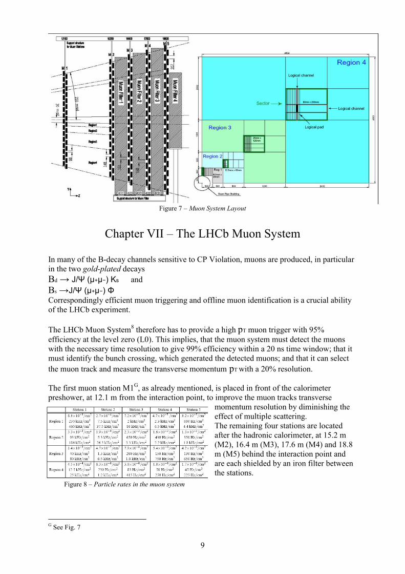
Figure 7 – Muon System Layout
Chapter VII – The LHCb Muon System
In many of the B-decay channels sensitive to CP Violation, muons are produced, in particular in the two gold-plated decays Bd → J/Ψ (μ+μ−) Ks and Bs →J/Ψ (μ+μ−) Φ
Correspondingly efficient muon triggering and offline muon identification is a crucial ability of the LHCb experiment. The LHCb Muon System8 therefore has to provide a high pT muon trigger with 95% efficiency at the level zero (L0). This implies, that the muon system must detect the muons with the necessary time resolution to give 99% efficiency within a 20 ns time window; that it must identify the bunch crossing, which generated the detected muons; and that it can select the muon track and measure the transverse momentum pT with a 20% resolution. The first muon station M1G, as already mentioned, is placed in front of the calorimeter preshower, at 12.1 m from the interaction point, to improve the muon tracks transverse
momentum resolution by diminishing the effect of multiple scattering. The remaining four stations are located after the hadronic calorimeter, at 15.2 m (M2), 16.4 m (M3), 17.6 m (M4) and 18.8 m (M5) behind the interaction point and are each shielded by an iron filter between the stations.
G See Fig. 7
Figure 8 – Particle rates in the muon system
Geneva, 02.01.2012 10
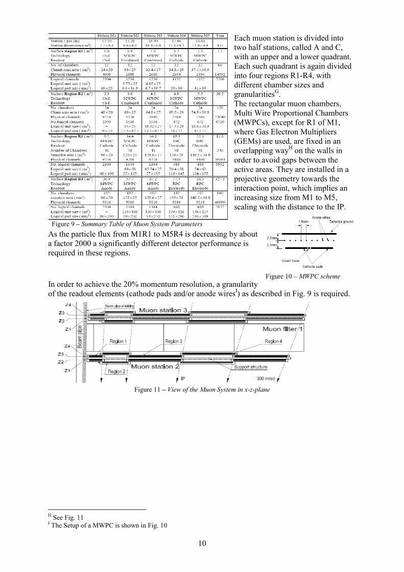
Each muon station is divided into two half stations, called A and C, with an upper and a lower quadrant. Each such quadrant is again divided into four regions R1-R4, with different chamber sizes and granularitiesG. The rectangular muon chambers, Multi Wire Proportional Chambers (MWPCs), except for R1 of M1, where Gas Electron Multipliers (GEMs) are used, are fixed in an overlapping wayH on the walls in order to avoid gaps between the active areas. They are installed in a projective geometry towards the interaction point, which implies an increasing size from M1 to M5, scaling with the distance to the IP.
As the particle flux from M1R1 to M5R4 is decreasing by about a factor 2000 a significantly different detector performance is required in these regions.
In order to achieve the 20% momentum resolution, a granularity of the readout elements (cathode pads and/or anode wiresI) as described in Fig. 9 is required.
Figure 11 – View of the Muon System in x-z-plane
H See Fig. 11 I The Setup of a MWPC is shown in Fig. 10
10m
Figure 9 – Summary Table of Muon System Parameters
Figure 10 – MWPC scheme
Geneva, 02.01.2012 11
Figure 13 – Moving the muon walls
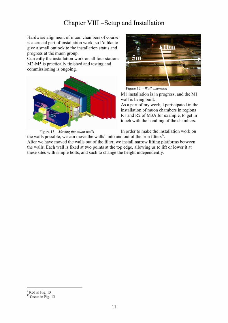
Chapter VIII –Setup and Installation Hardware alignment of muon chambers of course is a crucial part of installation work, so I’d like to give a small outlook to the installation status and progress at the muon group. Currently the installation work on all four stations M2-M5 is practically finished and testing and commissioning is ongoing.
M1 installation is in progress, and the M1 wall is being built. As a part of my work, I participated in the installation of muon chambers in regions R1 and R2 of M3A for example, to get in touch with the handling of the chambers. In order to make the installation work on
the walls possible, we can move the wallsJ into and out of the iron filtersK. After we have moved the walls out of the filter, we install narrow lifting platforms between the walls. Each wall is fixed at two points at the top edge, allowing us to lift or lower it at these sites with simple bolts, and such to change the height independently.
J Red in Fig. 13 K Green in Fig. 13
Figure 12 – Wall extension
10m 5m
Geneva, 02.01.2012 12
‘Learning by doing’
The Project Alignment of MWP Muon Chambers
Chapter IX – Hardware Alignment
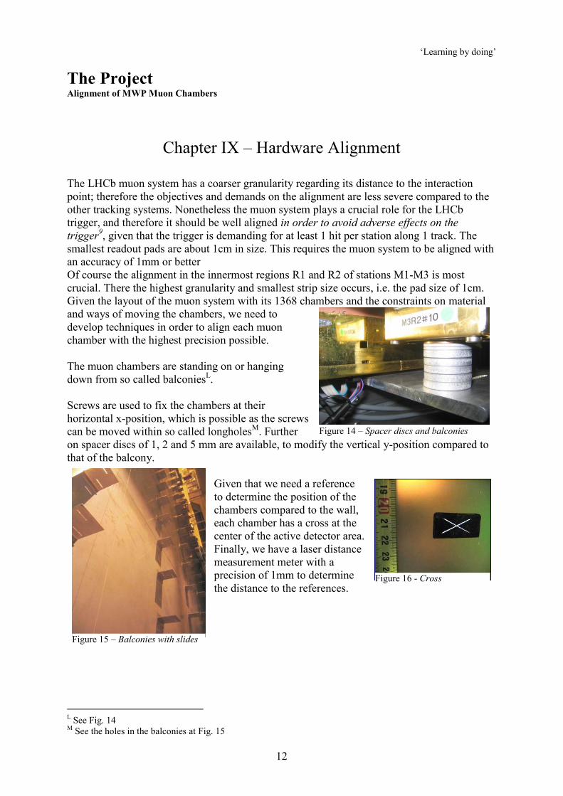
The LHCb muon system has a coarser granularity regarding its distance to the interaction point; therefore the objectives and demands on the alignment are less severe compared to the other tracking systems. Nonetheless the muon system plays a crucial role for the LHCb trigger, and therefore it should be well aligned in order to avoid adverse effects on the trigger9, given that the trigger is demanding for at least 1 hit per station along 1 track. The smallest readout pads are about 1cm in size. This requires the muon system to be aligned with an accuracy of 1mm or better Of course the alignment in the innermost regions R1 and R2 of stations M1-M3 is most crucial. There the highest granularity and smallest strip size occurs, i.e. the pad size of 1cm. Given the layout of the muon system with its 1368 chambers and the constraints on material and ways of moving the chambers, we need to develop techniques in order to align each muon chamber with the highest precision possible. The muon chambers are standing on or hanging down from so called balconiesL. Screws are used to fix the chambers at their horizontal x-position, which is possible as the screws can be moved within so called longholesM. Further on spacer discs of 1, 2 and 5 mm are available, to modify the vertical y-position compared to that of the balcony.
Given that we need a reference to determine the position of the chambers compared to the wall, each chamber has a cross at the center of the active detector area. Finally, we have a laser distance measurement meter with a precision of 1mm to determine the distance to the references.
L See Fig. 14 M See the holes in the balconies at Fig. 15
Figure 14 – Spacer discs and balconies
Figure 15 – Balconies with slides
Figure 16 - Cross
Geneva, 02.01.2012 13
A B C D 31 1
+
+ +
+ +
+
+ + + + + + + + + + + + + +
+ + + + + + + + + + + + + + +
+ + + + + + + + + +
+ + + + + + + + + + + + + + + + + + + + + + + +
+ +
+ + +
+ + + +
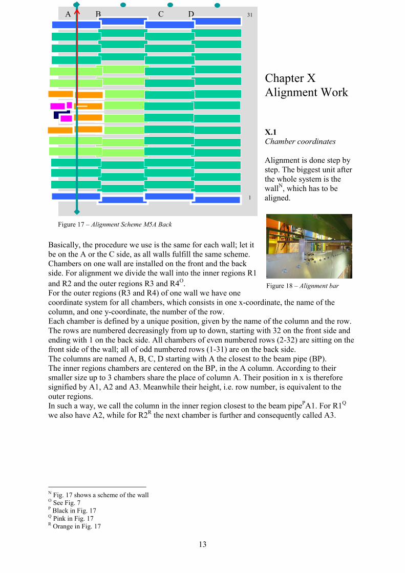
Figure 17 – Alignment Scheme M5A Back
Chapter X Alignment Work
X.1 Chamber coordinates Alignment is done step by step. The biggest unit after the whole system is the wallN, which has to be aligned.
Basically, the procedure we use is the same for each wall; let it be on the A or the C side, as all walls fulfill the same scheme. Chambers on one wall are installed on the front and the back side. For alignment we divide the wall into the inner regions R1 and R2 and the outer regions R3 and R4O. For the outer regions (R3 and R4) of one wall we have one coordinate system for all chambers, which consists in one x-coordinate, the name of the column, and one y-coordinate, the number of the row. Each chamber is defined by a unique position, given by the name of the column and the row. The rows are numbered decreasingly from up to down, starting with 32 on the front side and ending with 1 on the back side. All chambers of even numbered rows (2-32) are sitting on the front side of the wall; all of odd numbered rows (1-31) are on the back side. The columns are named A, B, C, D starting with A the closest to the beam pipe (BP). The inner regions chambers are centered on the BP, in the A column. According to their smaller size up to 3 chambers share the place of column A. Their position in x is therefore signified by A1, A2 and A3. Meanwhile their height, i.e. row number, is equivalent to the outer regions. In such a way, we call the column in the inner region closest to the beam pipePA1. For R1Q we also have A2, while for R2R the next chamber is further and consequently called A3.
N Fig. 17 shows a scheme of the wall O See Fig. 7 P Black in Fig. 17 Q Pink in Fig. 17 R Orange in Fig. 17
Figure 18 – Alignment bar
Geneva, 02.01.2012 14
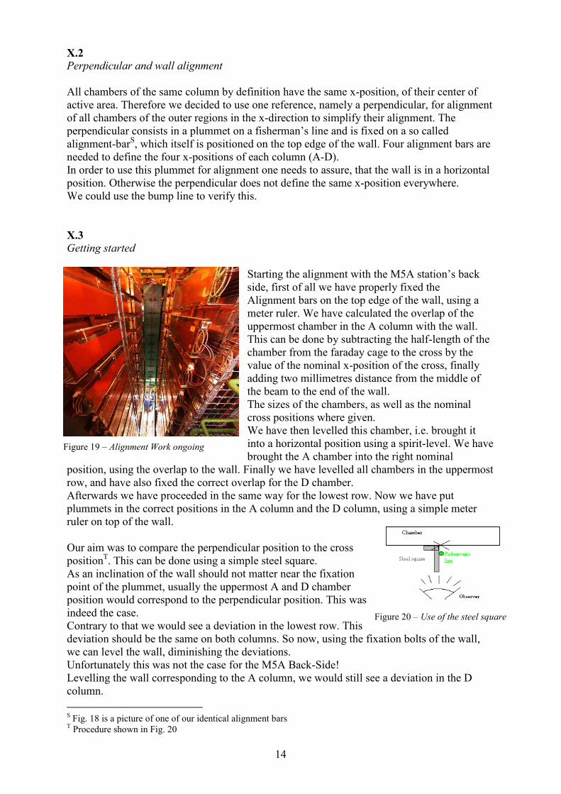
X.2 Perpendicular and wall alignment All chambers of the same column by definition have the same x-position, of their center of active area. Therefore we decided to use one reference, namely a perpendicular, for alignment of all chambers of the outer regions in the x-direction to simplify their alignment. The perpendicular consists in a plummet on a fisherman’s line and is fixed on a so called alignment-barS, which itself is positioned on the top edge of the wall. Four alignment bars are needed to define the four x-positions of each column (A-D). In order to use this plummet for alignment one needs to assure, that the wall is in a horizontal position. Otherwise the perpendicular does not define the same x-position everywhere. We could use the bump line to verify this. X.3 Getting started
Starting the alignment with the M5A station’s back side, first of all we have properly fixed the Alignment bars on the top edge of the wall, using a meter ruler. We have calculated the overlap of the uppermost chamber in the A column with the wall. This can be done by subtracting the half-length of the chamber from the faraday cage to the cross by the value of the nominal x-position of the cross, finally adding two millimetres distance from the middle of the beam to the end of the wall. The sizes of the chambers, as well as the nominal cross positions where given. We have then levelled this chamber, i.e. brought it into a horizontal position using a spirit-level. We have brought the A chamber into the right nominal
position, using the overlap to the wall. Finally we have levelled all chambers in the uppermost row, and have also fixed the correct overlap for the D chamber. Afterwards we have proceeded in the same way for the lowest row. Now we have put plummets in the correct positions in the A column and the D column, using a simple meter ruler on top of the wall. Our aim was to compare the perpendicular position to the cross positionT. This can be done using a simple steel square. As an inclination of the wall should not matter near the fixation point of the plummet, usually the uppermost A and D chamber position would correspond to the perpendicular position. This was indeed the case. Contrary to that we would see a deviation in the lowest row. This deviation should be the same on both columns. So now, using the fixation bolts of the wall, we can level the wall, diminishing the deviations. Unfortunately this was not the case for the M5A Back-Side! Levelling the wall corresponding to the A column, we would still see a deviation in the D column. S Fig. 18 is a picture of one of our identical alignment bars T Procedure shown in Fig. 20
Figure 19 – Alignment Work ongoing
Figure 20 – Use of the steel square
Geneva, 02.01.2012 15
X.4 A first problem: inaccuracy of the wall and the perpendicular Using the laser distance meter we could measure the distance from the A to the D chamber and such calculate the length of the wall. We have seen in doing so, that the wall was much larger on the bottom than on the top, corresponding to the theoretical expectations on the top only. That means that we had to give up the outer edge of the wall as a reference. We therefore have put the D chambers in the right distance to the A chambers. While the perpendicular was matching with the chambers of column A, it was not matching with those of column D. As the most stringent demands on accuracy are at column A in order to guarantee the needed precision for the inner chambers, therefore readjustments are rather possible in column D. Finally the perpendicular of course is in the same distance everywhere. But we still have observed small deviations. So we have changed the method of fixing the plummet and put it into water buckets on the ground, decreasing the natural effect of swinging, a possible source of errors. Further on we have investigated the wall, and we have found that it made a small curve in the middle part, with a curvature of up to 5mm, influencing our methods of measurement, because of an angle for the alignment bars and the steel square. We have calculated this effect and adjusted the position of the alignment bars. We could in such a way align the wall properly. X.5 The inner part Once the wall is aligned, the next step is to align the inner part (R1 and R2). We first level each chamber. Then we align those chambers which are the closest to the BP cut out or the inner wall edge (A1 and A2). We use a ruler to measure their overlaps in x and y and position the chamber properly according to this overlap. For the chambers located further to the outer edge (A2 and A3), we use again the overlap in order to align them with their neighbours. In case of such difficult access, we take use of the balconies, which are shared by two chambers, and apply the correction in the y position from one chamber to its neighbour by putting a corresponding difference in spacer discs. X.6 The intermediate part As the center of the inner chambers does not correspond to the position of the alignment bar of column A, we have marked auxiliary crosses on those inner chambers that are crossed by the perpendicular (the A1 chambers on the M5A Back-Side) by calculating the distance in the x-positions of A1 to A, for example, and then by shifting the cross there. To assure that the reference of the outer part, hence the alignment-bar, and the reference of the inner part, the BP cut out, are in accordance, such that the whole wall can be aligned properly in x, the auxiliary cross must meet with the perpendicular; in y we can now measure the distance from the auxiliary cross to the alignment bar and compare to the nominal values. Seeing a general offset in the x-position or the y-position, would mean, that our two references on the wall, the alignment bar and the beam pipe cut out, would not fit together.
Geneva, 02.01.2012 16
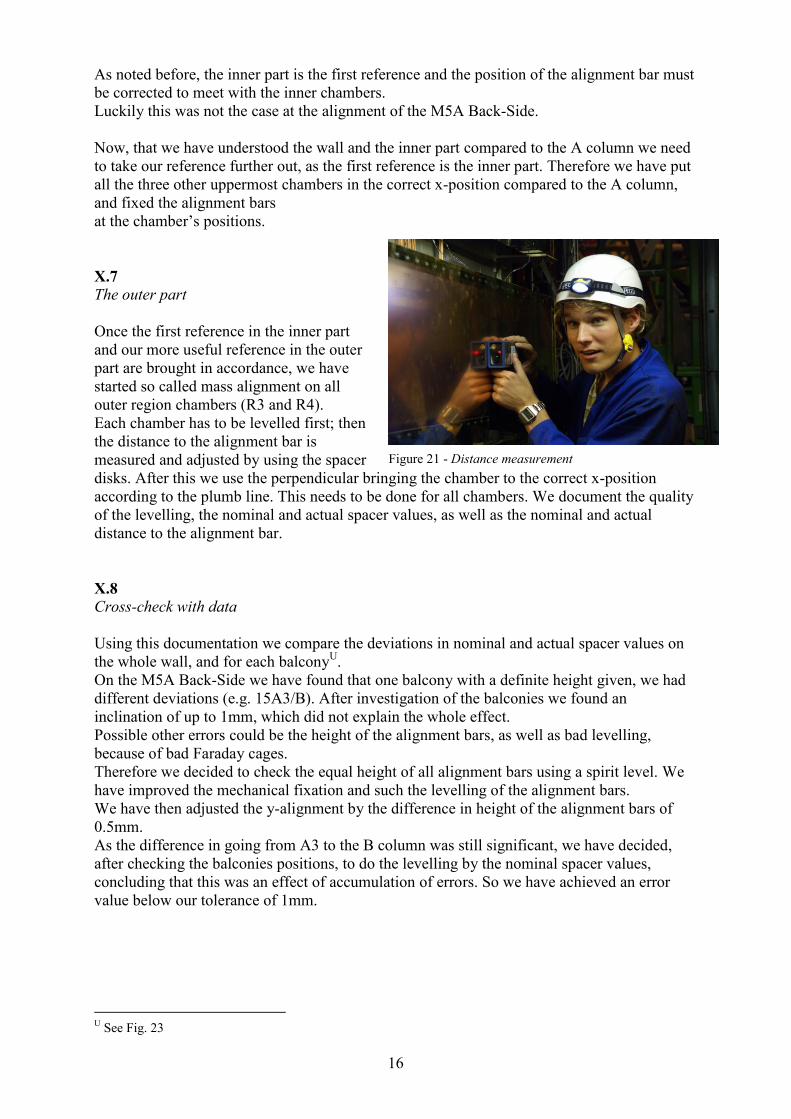
As noted before, the inner part is the first reference and the position of the alignment bar must be corrected to meet with the inner chambers. Luckily this was not the case at the alignment of the M5A Back-Side. Now, that we have understood the wall and the inner part compared to the A column we need to take our reference further out, as the first reference is the inner part. Therefore we have put all the three other uppermost chambers in the correct x-position compared to the A column, and fixed the alignment bars at the chamber’s positions. X.7 The outer part Once the first reference in the inner part and our more useful reference in the outer part are brought in accordance, we have started so called mass alignment on all outer region chambers (R3 and R4). Each chamber has to be levelled first; then the distance to the alignment bar is measured and adjusted by using the spacer disks. After this we use the perpendicular bringing the chamber to the correct x-position according to the plumb line. This needs to be done for all chambers. We document the quality of the levelling, the nominal and actual spacer values, as well as the nominal and actual distance to the alignment bar. X.8 Cross-check with data Using this documentation we compare the deviations in nominal and actual spacer values on the whole wall, and for each balconyU. On the M5A Back-Side we have found that one balcony with a definite height given, we had different deviations (e.g. 15A3/B). After investigation of the balconies we found an inclination of up to 1mm, which did not explain the whole effect. Possible other errors could be the height of the alignment bars, as well as bad levelling, because of bad Faraday cages. Therefore we decided to check the equal height of all alignment bars using a spirit level. We have improved the mechanical fixation and such the levelling of the alignment bars. We have then adjusted the y-alignment by the difference in height of the alignment bars of 0.5mm. As the difference in going from A3 to the B column was still significant, we have decided, after checking the balconies positions, to do the levelling by the nominal spacer values, concluding that this was an effect of accumulation of errors. So we have achieved an error value below our tolerance of 1mm.
U See Fig. 23
Figure 21 - Distance measurement
Geneva, 02.01.2012 17
Chapter XI – Problematic points
As one can see, during my work on muon chamber alignment some unexpected problems had to be solved in order to reach our precision of 1mm.
1. A first problematic point, I have already mentioned, was the wall precision. This implies on the one hand the curvature of the wall, but on the other hand the height of the wall, too. The wall shape changes with the lifting and lowering procedure of the wall, which means that we have to align one whole wall, before closing for example can be done. Because after closing all we see of the wall is the top, therefore we need to bring the top in the right reference to the inner part and measure the top positions properly before closing. And of course we need to understand the wall shape for alignment.
2. A second problem has been the precision of Faraday cages, used to measure the position and the overlap of chambers. Sometimes the cross just is not a useful tool so that we need to rely on the Faraday cage. The only way to improve this was by using the laser distance meter and measuring between different chambers to find a satisfying compromise.
3. A third point would be the problem of levelling, concerning the quality of faraday cages. We have solved this by giving more emphasis on the nominal spacer values.
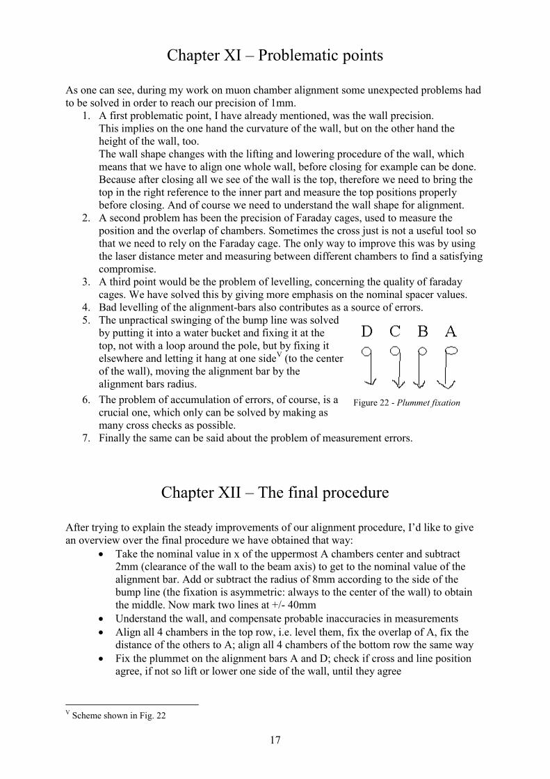
4. Bad levelling of the alignment-bars also contributes as a source of errors. 5. The unpractical swinging of the bump line was solved
by putting it into a water bucket and fixing it at the top, not with a loop around the pole, but by fixing it elsewhere and letting it hang at one sideV (to the center of the wall), moving the alignment bar by the alignment bars radius.
6. The problem of accumulation of errors, of course, is a crucial one, which only can be solved by making as many cross checks as possible.
7. Finally the same can be said about the problem of measurement errors.
Chapter XII – The final procedure
After trying to explain the steady improvements of our alignment procedure, I’d like to give an overview over the final procedure we have obtained that way:
x Take the nominal value in x of the uppermost A chambers center and subtract 2mm (clearance of the wall to the beam axis) to get to the nominal value of the alignment bar. Add or subtract the radius of 8mm according to the side of the bump line (the fixation is asymmetric: always to the center of the wall) to obtain the middle. Now mark two lines at +/- 40mm
x Understand the wall, and compensate probable inaccuracies in measurements x Align all 4 chambers in the top row, i.e. level them, fix the overlap of A, fix the
distance of the others to A; align all 4 chambers of the bottom row the same way x Fix the plummet on the alignment bars A and D; check if cross and line position
agree, if not so lift or lower one side of the wall, until they agree
V Scheme shown in Fig. 22
Figure 22 - Plummet fixation
Geneva, 02.01.2012 18
x Align the inner regions R1 and R2; level the inner chambers, bring them into correct x and y overlap positions, go to the next outer chamber, adjust the x overlap; compare the nominal spacer values and add the difference to the spacers of the neighbour chambers; do so for the whole inner region
x Control balconies, and compensate for inaccuracies x Fix alignment bars on B and C; level them all four; control the height of the
alignment bars x Make a virtual cross an the fictive A position; control agreement with line and
measure distance to the alignment bar; if a general offset occurs, adjust the outer part, if not bring inner part in accordance
x Now begin mass alignment; level the chamber, compare deviation at one balcony to nominal values and balcony quality; measure and adjust distance to alignment bar, according to nominal value and height of the bar; align chamber in x with the perpendicular
x Now cross check the inner and outer part; adjust large deviations at the borders, explained by an accumulation of errors using a compromise; measure distance from inner to outer part doing this; keep the inner part as the first reference
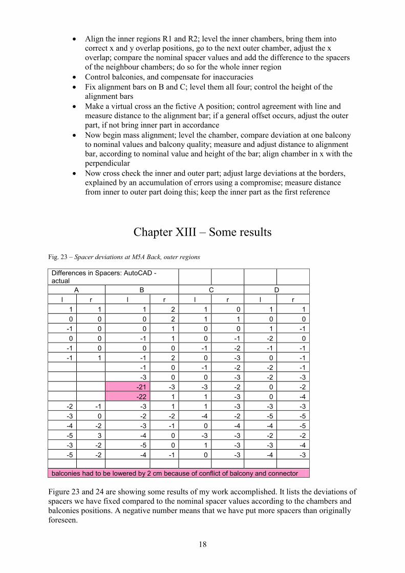
Chapter XIII – Some results Fig. 23 – Spacer deviations at M5A Back, outer regions Differences in Spacers: AutoCAD - actual
A B C D l r l r l r l r
1 1 1 2 1 0 1 1 0 0 0 2 1 1 0 0
-1 0 0 1 0 0 1 -1 0 0 -1 1 0 -1 -2 0
-1 0 0 0 -1 -2 -1 -1 -1 1 -1 2 0 -3 0 -1
-1 0 -1 -2 -2 -1 -3 0 0 -3 -2 -3 -21 -3 -3 -2 0 -2 -22 1 1 -3 0 -4
-2 -1 -3 1 1 -3 -3 -3 -3 0 -2 -2 -4 -2 -5 -5 -4 -2 -3 -1 0 -4 -4 -5 -5 3 -4 0 -3 -3 -2 -2 -3 -2 -5 0 1 -3 -3 -4 -5 -2 -4 -1 0 -3 -4 -3
balconies had to be lowered by 2 cm because of conflict of balcony and connector
Figure 23 and 24 are showing some results of my work accomplished. It lists the deviations of spacers we have fixed compared to the nominal spacer values according to the chambers and balconies positions. A negative number means that we have put more spacers than originally foreseen.
Geneva, 02.01.2012 19
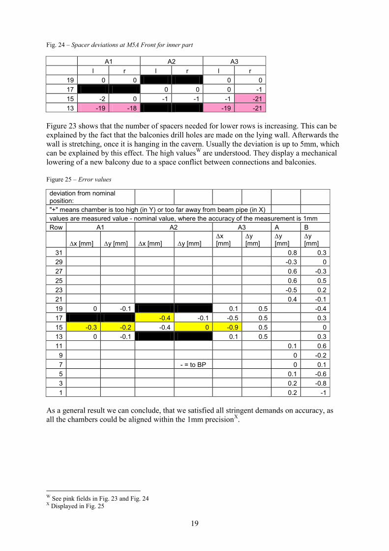
Fig. 24 – Spacer deviations at M5A Front for inner part
A1 A2 A3 l r l r l r
19 0 0 0 0 17 0 0 0 -1 15 -2 0 -1 -1 -1 -21 13 -19 -18 -19 -21
Figure 23 shows that the number of spacers needed for lower rows is increasing. This can be explained by the fact that the balconies drill holes are made on the lying wall. Afterwards the wall is stretching, once it is hanging in the cavern. Usually the deviation is up to 5mm, which can be explained by this effect. The high valuesW are understood. They display a mechanical lowering of a new balcony due to a space conflict between connections and balconies. Figure 25 – Error values deviation from nominal position: "+" means chamber is too high (in Y) or too far away from beam pipe (in X) values are measured value - nominal value, where the accuracy of the measurement is 1mm Row A1 A2 A3 A B
'x [mm]� 'y [mm]� 'x [mm]� 'y [mm]�'x [mm]�
'y [mm]�
'y [mm]�
'y [mm]�
31 0.8 0.3 29 -0.3 0 27 0.6 -0.3 25 0.6 0.5 23 -0.5 0.2 21 0.4 -0.1 19 0 -0.1 0.1 0.5 -0.4 17 -0.4 -0.1 -0.5 0.5 0.3 15 -0.3 -0.2 -0.4 0 -0.9 0.5 0 13 0 -0.1 0.1 0.5 0.3 11 0.1 0.6
9 0 -0.2 7 - = to BP 0 0.1 5 0.1 -0.6 3 0.2 -0.8 1 0.2 -1
As a general result we can conclude, that we satisfied all stringent demands on accuracy, as all the chambers could be aligned within the 1mm precisionX. W See pink fields in Fig. 23 and Fig. 24 X Displayed in Fig. 25
Geneva, 02.01.2012 20
Conclusions The experimental work, ‘learning by doing’, has been a very enriching experience for me. Understanding simple experimental techniques and learning to apply them successfully in physics seems more than useful to me. During my experience the alignment procedure and tools could be improved steadily. Unexpected deviations and inaccuracies of the hardware could be pointed out and understood. We could therefore finish the alignment of the complete M5A wall and the M4A Back-Side before closing the whole A-Side, to understand its behaviour under this procedure. Currently work is still ongoing on the C-Side. We intend to keep our tight schedule, as we become faster and faster. References 1 http://press.web.cern.ch/press/PressReleases/Releases2007/PR06.07E.html 2 http://lhc-machine-outreach.web.cern.ch/lhc-machine-outreach/lhc-vital-statistics.htm 3 http://indico.cern.ch/getFile.py/access?resId=1&materialId=slides&confId=a07125 4 http://atlas.web.cern.ch/Atlas/GROUPS/notes.html 5 http://cms.cern.ch/iCMS/jsp/page.jsp?mode=cms&action=url&urlkey=CMS_TDRS 6 http://aliceinfo.cern.ch/ 7 ‘Instruments for calibration and monitoring of the LHCb Muon Detector’, Caterina Deplano, CERN-Thesis-2006-010 8 ‘LHCb Muon System Technical Design Report’ ; http://lhcb-muon.web.cern.ch/lhcb-muon/results/tdr.pdf 9 Baldini et al. ‘Overview of LHCb alignment’, CERN 2007-004 p. 197-222