Embed Size (px)
Citation preview
TM
TM
Thi
s gu
ide
for
use
by q
uali
fied
inst
alle
rs o
nly.
Freedom SWSine Wave Inverter/Chargers
Installation Guide
FREEDOM SW 3012
FREEDOM SW 3012
FREEDOM SW 3012
FREEDOM SW 3012CLEAR FAULTRESET INVERTER
ENABLE
INVERTERENABLED
AC IN
FAULT
GENSUPPORT CHARGINGWARNING
CLEAR FAULT
RESET
INVERTER
ENABLE
INVERTER
ENABLED
AC IN
FAULT
GEN
SUPPORT
CHARGINGWARNING
Freedom SW 3012 shown.
Model Numbers815-3012, 815-3024815-2012, 815-2024

Thi
s gu
ide
for
use
by q
uali
fied
inst
alle
rs o
nly.
TrademarksSchneider Electric, the Schneider Electric logo, and Xantrex are trademarks or registered trademarks of the Schneider Electric group of companies. Other trademarks, registered trademarks, and product names are the property of their respective owners and are used herein for identification purposes only.
Notice of CopyrightFreedom SW Sine Wave Inverter/Chargers Installation Guide © 2011-2012 Xantrex Technology Inc. All rights reserved. No part of this document may be reproduced in any form or disclosed to third parties without the express written consent of: Xantrex Technology Inc., 161-G South Vasco Rd., Livermore, California, USA 94551. Xantrex Technology Inc. reserves the right to revise this document and to periodically make changes to the content hereof without obligation or organization of such revisions or changes unless required to do so by prior arrangement.
All warranty, disclaimer and safety information is contained within the primary documentation received with your unit. Unless specified, safety, installation, operation and specification information is as shown in the primary documentation. Please ensure you are familiar with that information before proceeding.
Exclusion for DocumentationUNLESS SPECIFICALLY AGREED TO IN WRITING, SELLER
(A) MAKES NO WARRANTY AS TO THE ACCURACY, SUFFICIENCY OR SUITABILITY OF ANY TECHNICAL OR OTHER INFORMATION PROVIDED IN ITS MANUALS OR OTHER DOCUMENTATION;(B) ASSUMES NO RESPONSIBILITY OR LIABILITY FOR LOSSES, DAMAGES, COSTS OR EXPENSES, WHETHER SPECIAL, DIRECT, INDIRECT, CONSEQUENTIAL OR INCIDENTAL, WHICH MIGHT ARISE OUT OF THE USE OF SUCH INFORMATION. THE USE OF ANY SUCH INFORMATION WILL BE ENTIRELY AT THE USER’S RISK; AND
(C) REMINDS YOU THAT IF THIS MANUAL IS IN ANY LANGUAGE OTHER THAN ENGLISH, ALTHOUGH STEPS HAVE BEEN TAKEN TO MAINTAIN THE ACCURACY OF THE TRANSLATION, THE ACCURACY CANNOT BE GUARANTEED. APPROVED XANTREX CONTENT IS CONTAINED WITH THE ENGLISH LANGUAGE VERSION WHICH IS POSTED AT WWW.XANTREX.COM.
Date and RevisionFebruary 2012 Rev B
To view, download, or print the latest revision, visit the website shown under Contact Information.
Document Part Number97-0020-01-01
Product Numbers815-2012 (Freedom SW 2012), 815-2024 (Freedom SW 2024)815-3012 (Freedom SW 3012), 815-3024 (Freedom SW 3024)
Contact InformationTelephone: 1 800 670 0707 (toll free North America)
1 408 987 6030 (direct)
Web: www.xantrex.com
97-0020-01-01 i
About This Guide
PurposeThe purpose of this Installation Guide is to provide explanations and procedures for installing the Freedom SW Inverter/Charger.
ScopeThe Guide provides safety and installation guidelines as well as information on tools and wiring. It does not provide details about particular brands of batteries. You need to consult individual battery manufacturers for this information.
AudienceThe guide is intended for qualified installers and technicians of the Freedom SW Inverter/Charger.
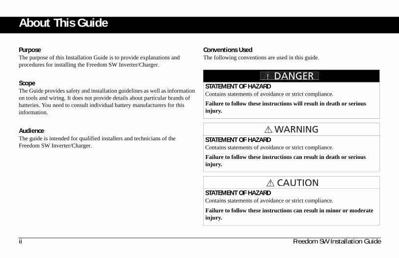
Conventions UsedThe following conventions are used in this guide.
STATEMENT OF HAZARDContains statements of avoidance or strict compliance.
Failure to follow these instructions will result in death or serious injury.
STATEMENT OF HAZARDContains statements of avoidance or strict compliance.
Failure to follow these instructions can result in death or serious injury.
STATEMENT OF HAZARDContains statements of avoidance or strict compliance.
Failure to follow these instructions can result in minor or moderate injury.
ii Freedom SW Installation Guide
Thi
s gu
ide
for
use
by q
uali
fied
inst
alle
rs o
nly.
Related InformationYou can find more information about Xantrex Technology Inc. as well as its products and services at www.xantrex.com.
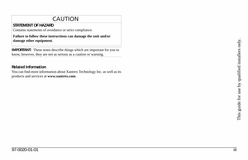
STATEMENT OF HAZARDContains statements of avoidance or strict compliance.
Failure to follow these instructions can damage the unit and/or damage other equipment.
IMPORTANT: These notes describe things which are important for you to know, however, they are not as serious as a caution or warning.
97-0020-01-01 iii
Important Safety Instructions
IMPORTANT: READ AND SAVE THIS INSTALLATION GUIDE FOR FUTURE REFERENCE.
This chapter contains important safety and installation instructions for the Freedom SW Inverter/Charger (Freedom SW). Each time, before using the Freedom SW, READ ALL instructions and cautionary markings on or provided with the inverter/charger, the batteries, and all appropriate sections of this guide.
NOTE: The Freedom SW contains no user-serviceable parts. See “Warranty and Return Information” on the Owner’s Guide for guidance.
NOTE: Turning off the inverter/charger using the on/off switch on the front panel will not reduce an electrical shock hazard.
ELECTRICAL SHOCK HAZARD• Do not expose the Freedom SW to rain, snow, spray, or bilge water.
This inverter/charger is designed for marine applications only when additional drip protection is installed in certain orientations. See the installation guide for information.
• Do not operate the inverter/charger if it has received a sharp blow, been dropped, has cracks or openings in the enclosure including if the fuse cover has been lost, damaged, or will not close, or otherwise damaged in any other way.
• Do not disassemble the inverter/charger. Internal capacitors remain charged after all power is disconnected.
• Disconnect both AC and DC power from the inverter/charger before attempting any maintenance or cleaning or working on any circuits connected to the inverter/charger. See note below.
• Do not operate the inverter/charger with damaged or substandard wiring. Make sure that all wiring is in good condition and is not undersized.
Failure to follow these instructions will result in death or serious injury.
iv Freedom SW Installation Guide
Thi
s gu
ide
for
use
by q
uali
fied
inst
alle
rs o
nly.
NOTES:1. Follow these instructions and those published by the battery
manufacturer and the manufacturer of any equipment you intend to use in the vicinity of the battery. Review cautionary markings on these products and on the engine.
2. This inverter/charger contains components which tend to produce arcs or sparks.
3. Locations include any space containing gasoline-powered machinery, fuel tanks, as well as joints, fittings, or other connections between components of the fuel system.
FIRE AND BURN HAZARD• Do not cover or obstruct the air intake vent openings and/or install in
a zero-clearance compartment.• Do not use transformerless battery chargers in conjunction with the
inverter/charger due to overheating.
Failure to follow these instructions will result in death or serious injury.
EXPLOSION HAZARD• Charge only properly rated (such as 12 V) lead-acid (GEL, AGM,
Flooded, or lead-calcium) rechargeable batteries because other battery types may explode and burst.
• Do not work in the vicinity of lead-acid batteries. Batteries generate explosive gases during normal operation. See note #1.
• Do not install and/or operate in compartments containing flammable materials or in locations that require ignition-protected equipment. See notes #2 and #3.
Failure to follow these instructions will result in death or serious injury.
97-0020-01-01 v
Precautions When Working With Batteries
NOTES:1. Mount and place the Freedom SW Inverter/Charger unit away from
batteries in a well ventilated compartment.
2. Always have someone within range of your voice or close enough to come to your aid when you work near a lead-acid battery.
3. Always have plenty of fresh water and soap nearby in case battery acid contacts skin, clothing, or eyes.
4. If battery acid contacts skin or clothing, wash immediately with soap and water. If acid enters your eye, immediately flood it with running cold water for at least twenty minutes and get medical attention immediately.
5. Use extra caution to reduce the risk or dropping a metal tool on the battery. It could spark or short circuit the battery or other electrical parts and could cause an explosion.
6. Batteries can produce a short circuit current high enough to weld a ring or metal bracelet or the like to the battery terminal, causing a severe burn.
7. When removing a battery, always remove the negative terminal from the battery first for systems with grounded negative. If it is grounded positive, remove the positive terminal first. Make sure all loads connected to the battery and all accessories are off so you don’t cause an arc.
BURN FROM HIGH SHORT-CIRCUIT CURRENT, FIRE AND EXPLO-SION FROM VENTED GASES HAZARDS• Always wear proper, non-absorbent gloves, complete eye protection,
and clothing protection. Avoid touching your eyes and wiping your forehead while working near batteries. See note #4.
• Remove all personal metal items, like rings, bracelets, and watches when working with batteries. See notes #5 and #6 below.
• Never smoke or allow a spark or flame near the engine or batteries.• Never charge a frozen battery.
Failure to follow these instructions can result in death or serious injury.
vi Freedom SW Installation Guide
Thi
s gu
ide
for
use
by q
uali
fied
inst
alle
rs o
nly.
Precautions When Preparing to Charge
NOTES:• Study and follow all of the battery manufacturer's specific precautions,
such as removing or not removing cell caps while charging, whether equalization is acceptable for your battery, and recommended rates of charge.
• For flooded non-sealed batteries, add distilled water in each cell until battery acid reaches the level specified by the battery manufacturer. This helps to purge excessive gas from cells. Do not overfill. For a battery without removable cell caps, carefully follow manufacturer's instructions.
Precautions When Placing the Inverter/Charger
EXPOSURE TO CHEMICALS AND GASES HAZARD• Make sure the area around the battery is well ventilated.• Make sure the voltage of the batteries matches the output voltage of
the inverter/charger.• Be careful to keep corrosion from coming into contact with your eyes
and skin when cleaning battery terminals.
Failure to follow these instructions can result in death or serious injury.
RISK OF DAMAGE TO THE INVERTER/CHARGER• Never allow battery acid to drip on the inverter/charger when reading
gravity, or filling battery.• Never place the Freedom SW Inverter/Charger unit directly above
batteries; gases from a battery will corrode and damage the inverter/charger.
• Do not place a battery on top of the inverter/charger.
Failure to follow these instructions can damage the unit and/or damage other equipment.
97-0020-01-01 vii
RegulatoryThe Freedom SW Inverter/Charger is certified to appropriate US and Canadian standards. For more information see “Regulatory Approvals” on the Specifications section in the Owner’s Guide.
The Freedom SW Inverter/Charger is intended to be used for mobile or commercial applications. This inverter/charger is designed for marine applications only when additional drip protection is installed in certain orientations.
It is not intended for other applications as it may not comply with the additional safety code requirements needed for those other applications. See “Limitations On Use” below.
FCC Information to the UserThis equipment has been tested and found to comply with the limits for a Class B digital device, pursuant to part 15 of the FCC Rules. These limits are designed to provide reasonable protection against harmful interference in a residential installation. This equipment generates, uses, and can radiate radio frequency energy and, if not installed and used in accordance with the instructions, may cause harmful interference to radio communications.
However, there is no guarantee that interference will not occur in a particular installation. If this equipment does cause harmful interference to radio or television reception, which can be determined by turning the equipment off and on, the user is encouraged to try to correct the interference by one or more of the following measures:
• Reorient or relocate the receiving antenna.• Increase the separation between the equipment and receiver.• Connect the equipment into an outlet on a circuit different from that to
which the receiver is connected.• Consult the dealer or an experienced radio/TV technician for help.
LIMITATIONS ON USE• Do not use in connection with life support systems or other medical
equipment or devices.• Do not use in ambulances or other life-saving emergency vehicles.
Failure to follow these instructions can result in death or serious injury.
Unauthorized changes or modifications to the equipment could void the user’s authority to operate the equipment.
viii Freedom SW Installation Guide
Thi
s gu
ide
for
use
by q
uali
fied
inst
alle
rs o
nly.
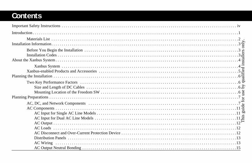
Contents
Important Safety Instructions . . . . . . . . . . . . . . . . . . . . . . . . . . . . . . . . . . . . . . . . . . . . . . . . . . . . . . . . . . . . . . . . . . . . . . . . . . . . . . . . . . . . . ivIntroduction . . . . . . . . . . . . . . . . . . . . . . . . . . . . . . . . . . . . . . . . . . . . . . . . . . . . . . . . . . . . . . . . . . . . . . . . . . . . . . . . . . . . . . . . . . . . . . . . . . . .1
Materials List . . . . . . . . . . . . . . . . . . . . . . . . . . . . . . . . . . . . . . . . . . . . . . . . . . . . . . . . . . . . . . . . . . . . . . . . . . . . . . . . . . . . . . . . . . .2Installation Information. . . . . . . . . . . . . . . . . . . . . . . . . . . . . . . . . . . . . . . . . . . . . . . . . . . . . . . . . . . . . . . . . . . . . . . . . . . . . . . . . . . . . . . . . . .3
Before You Begin the Installation . . . . . . . . . . . . . . . . . . . . . . . . . . . . . . . . . . . . . . . . . . . . . . . . . . . . . . . . . . . . . . . . . . . . . . . . . . .3Installation Codes . . . . . . . . . . . . . . . . . . . . . . . . . . . . . . . . . . . . . . . . . . . . . . . . . . . . . . . . . . . . . . . . . . . . . . . . . . . . . . . . . . . . . . . .3
About the Xanbus System . . . . . . . . . . . . . . . . . . . . . . . . . . . . . . . . . . . . . . . . . . . . . . . . . . . . . . . . . . . . . . . . . . . . . . . . . . . . . . . . . . . . . . . . .4
Xanbus System . . . . . . . . . . . . . . . . . . . . . . . . . . . . . . . . . . . . . . . . . . . . . . . . . . . . . . . . . . . . . . . . . . . . . . . . . . . . . . . . . . . . . .4Xanbus-enabled Products and Accessories . . . . . . . . . . . . . . . . . . . . . . . . . . . . . . . . . . . . . . . . . . . . . . . . . . . . . . . . . . . . . . . . . . . .5
Planning the Installation . . . . . . . . . . . . . . . . . . . . . . . . . . . . . . . . . . . . . . . . . . . . . . . . . . . . . . . . . . . . . . . . . . . . . . . . . . . . . . . . . . . . . . . . . .6
Two Key Performance Factors . . . . . . . . . . . . . . . . . . . . . . . . . . . . . . . . . . . . . . . . . . . . . . . . . . . . . . . . . . . . . . . . . . . . . . . . . . . . .6Size and Length of DC Cables . . . . . . . . . . . . . . . . . . . . . . . . . . . . . . . . . . . . . . . . . . . . . . . . . . . . . . . . . . . . . . . . . . . . . . . . . .6Mounting Location of the Freedom SW . . . . . . . . . . . . . . . . . . . . . . . . . . . . . . . . . . . . . . . . . . . . . . . . . . . . . . . . . . . . . . . . . . .6
Planning Preparations . . . . . . . . . . . . . . . . . . . . . . . . . . . . . . . . . . . . . . . . . . . . . . . . . . . . . . . . . . . . . . . . . . . . . . . . . . . . . . . . . . . . . . . . . . . .7
AC, DC, and Network Components . . . . . . . . . . . . . . . . . . . . . . . . . . . . . . . . . . . . . . . . . . . . . . . . . . . . . . . . . . . . . . . . . . . . . . . . .7AC Components . . . . . . . . . . . . . . . . . . . . . . . . . . . . . . . . . . . . . . . . . . . . . . . . . . . . . . . . . . . . . . . . . . . . . . . . . . . . . . . . . . . . . . . .11
AC Input for Single AC Line Models . . . . . . . . . . . . . . . . . . . . . . . . . . . . . . . . . . . . . . . . . . . . . . . . . . . . . . . . . . . . . . . . . . . .11AC Input for Dual AC Line Models . . . . . . . . . . . . . . . . . . . . . . . . . . . . . . . . . . . . . . . . . . . . . . . . . . . . . . . . . . . . . . . . . . . . .11AC Output . . . . . . . . . . . . . . . . . . . . . . . . . . . . . . . . . . . . . . . . . . . . . . . . . . . . . . . . . . . . . . . . . . . . . . . . . . . . . . . . . . . . . . . . .12AC Loads . . . . . . . . . . . . . . . . . . . . . . . . . . . . . . . . . . . . . . . . . . . . . . . . . . . . . . . . . . . . . . . . . . . . . . . . . . . . . . . . . . . . . . . . .12AC Disconnect and Over-Current Protection Device . . . . . . . . . . . . . . . . . . . . . . . . . . . . . . . . . . . . . . . . . . . . . . . . . . . . . . . .12Distribution Panels . . . . . . . . . . . . . . . . . . . . . . . . . . . . . . . . . . . . . . . . . . . . . . . . . . . . . . . . . . . . . . . . . . . . . . . . . . . . . . . . . .13AC Wiring . . . . . . . . . . . . . . . . . . . . . . . . . . . . . . . . . . . . . . . . . . . . . . . . . . . . . . . . . . . . . . . . . . . . . . . . . . . . . . . . . . . . . . . .13AC Output Neutral Bonding . . . . . . . . . . . . . . . . . . . . . . . . . . . . . . . . . . . . . . . . . . . . . . . . . . . . . . . . . . . . . . . . . . . . . . . . . . .15
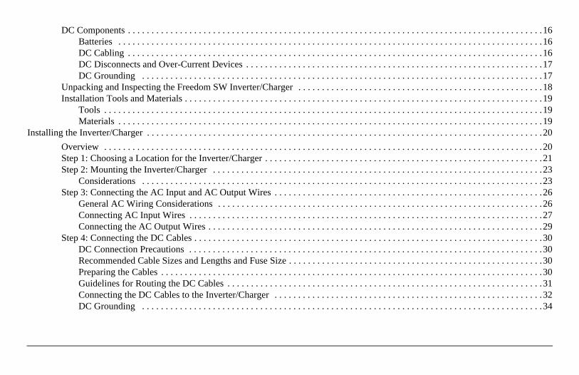
DC Components . . . . . . . . . . . . . . . . . . . . . . . . . . . . . . . . . . . . . . . . . . . . . . . . . . . . . . . . . . . . . . . . . . . . . . . . . . . . . . . . . . . . . . . .16Batteries . . . . . . . . . . . . . . . . . . . . . . . . . . . . . . . . . . . . . . . . . . . . . . . . . . . . . . . . . . . . . . . . . . . . . . . . . . . . . . . . . . . . . . . . . .16DC Cabling . . . . . . . . . . . . . . . . . . . . . . . . . . . . . . . . . . . . . . . . . . . . . . . . . . . . . . . . . . . . . . . . . . . . . . . . . . . . . . . . . . . . . . . .16DC Disconnects and Over-Current Devices . . . . . . . . . . . . . . . . . . . . . . . . . . . . . . . . . . . . . . . . . . . . . . . . . . . . . . . . . . . . . . .17DC Grounding . . . . . . . . . . . . . . . . . . . . . . . . . . . . . . . . . . . . . . . . . . . . . . . . . . . . . . . . . . . . . . . . . . . . . . . . . . . . . . . . . . . . .17
Unpacking and Inspecting the Freedom SW Inverter/Charger . . . . . . . . . . . . . . . . . . . . . . . . . . . . . . . . . . . . . . . . . . . . . . . . . . . .18Installation Tools and Materials . . . . . . . . . . . . . . . . . . . . . . . . . . . . . . . . . . . . . . . . . . . . . . . . . . . . . . . . . . . . . . . . . . . . . . . . . . . .19
Tools . . . . . . . . . . . . . . . . . . . . . . . . . . . . . . . . . . . . . . . . . . . . . . . . . . . . . . . . . . . . . . . . . . . . . . . . . . . . . . . . . . . . . . . . . . . . .19Materials . . . . . . . . . . . . . . . . . . . . . . . . . . . . . . . . . . . . . . . . . . . . . . . . . . . . . . . . . . . . . . . . . . . . . . . . . . . . . . . . . . . . . . . . . .19
Installing the Inverter/Charger . . . . . . . . . . . . . . . . . . . . . . . . . . . . . . . . . . . . . . . . . . . . . . . . . . . . . . . . . . . . . . . . . . . . . . . . . . . . . . . . . . . .20
Overview . . . . . . . . . . . . . . . . . . . . . . . . . . . . . . . . . . . . . . . . . . . . . . . . . . . . . . . . . . . . . . . . . . . . . . . . . . . . . . . . . . . . . . . . . . . . .20Step 1: Choosing a Location for the Inverter/Charger . . . . . . . . . . . . . . . . . . . . . . . . . . . . . . . . . . . . . . . . . . . . . . . . . . . . . . . . . . .21Step 2: Mounting the Inverter/Charger . . . . . . . . . . . . . . . . . . . . . . . . . . . . . . . . . . . . . . . . . . . . . . . . . . . . . . . . . . . . . . . . . . . . . .23
Considerations . . . . . . . . . . . . . . . . . . . . . . . . . . . . . . . . . . . . . . . . . . . . . . . . . . . . . . . . . . . . . . . . . . . . . . . . . . . . . . . . . . . . .23Step 3: Connecting the AC Input and AC Output Wires . . . . . . . . . . . . . . . . . . . . . . . . . . . . . . . . . . . . . . . . . . . . . . . . . . . . . . . . .26
General AC Wiring Considerations . . . . . . . . . . . . . . . . . . . . . . . . . . . . . . . . . . . . . . . . . . . . . . . . . . . . . . . . . . . . . . . . . . . . .26Connecting AC Input Wires . . . . . . . . . . . . . . . . . . . . . . . . . . . . . . . . . . . . . . . . . . . . . . . . . . . . . . . . . . . . . . . . . . . . . . . . . . .27Connecting the AC Output Wires . . . . . . . . . . . . . . . . . . . . . . . . . . . . . . . . . . . . . . . . . . . . . . . . . . . . . . . . . . . . . . . . . . . . . . .29
Step 4: Connecting the DC Cables . . . . . . . . . . . . . . . . . . . . . . . . . . . . . . . . . . . . . . . . . . . . . . . . . . . . . . . . . . . . . . . . . . . . . . . . . .30DC Connection Precautions . . . . . . . . . . . . . . . . . . . . . . . . . . . . . . . . . . . . . . . . . . . . . . . . . . . . . . . . . . . . . . . . . . . . . . . . . . .30Recommended Cable Sizes and Lengths and Fuse Size . . . . . . . . . . . . . . . . . . . . . . . . . . . . . . . . . . . . . . . . . . . . . . . . . . . . . .30Preparing the Cables . . . . . . . . . . . . . . . . . . . . . . . . . . . . . . . . . . . . . . . . . . . . . . . . . . . . . . . . . . . . . . . . . . . . . . . . . . . . . . . . .30Guidelines for Routing the DC Cables . . . . . . . . . . . . . . . . . . . . . . . . . . . . . . . . . . . . . . . . . . . . . . . . . . . . . . . . . . . . . . . . . . .31Connecting the DC Cables to the Inverter/Charger . . . . . . . . . . . . . . . . . . . . . . . . . . . . . . . . . . . . . . . . . . . . . . . . . . . . . . . . .32DC Grounding . . . . . . . . . . . . . . . . . . . . . . . . . . . . . . . . . . . . . . . . . . . . . . . . . . . . . . . . . . . . . . . . . . . . . . . . . . . . . . . . . . . . .34
Thi
s gu
ide
for
use
by q
uali
fied
inst
alle
rs o
nly.
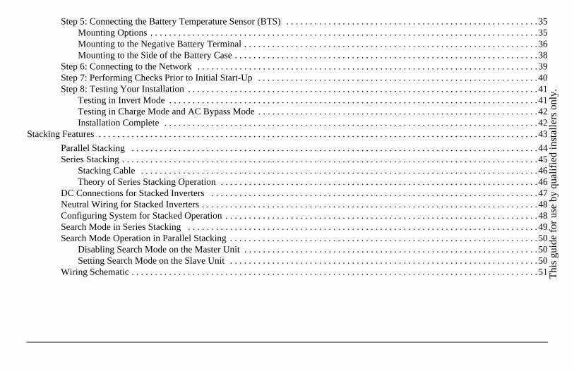
Step 5: Connecting the Battery Temperature Sensor (BTS) . . . . . . . . . . . . . . . . . . . . . . . . . . . . . . . . . . . . . . . . . . . . . . . . . . . . . .35Mounting Options . . . . . . . . . . . . . . . . . . . . . . . . . . . . . . . . . . . . . . . . . . . . . . . . . . . . . . . . . . . . . . . . . . . . . . . . . . . . . . . . . . .35Mounting to the Negative Battery Terminal . . . . . . . . . . . . . . . . . . . . . . . . . . . . . . . . . . . . . . . . . . . . . . . . . . . . . . . . . . . . . . .36Mounting to the Side of the Battery Case . . . . . . . . . . . . . . . . . . . . . . . . . . . . . . . . . . . . . . . . . . . . . . . . . . . . . . . . . . . . . . . . .38
Step 6: Connecting to the Network . . . . . . . . . . . . . . . . . . . . . . . . . . . . . . . . . . . . . . . . . . . . . . . . . . . . . . . . . . . . . . . . . . . . . . . . .39Step 7: Performing Checks Prior to Initial Start-Up . . . . . . . . . . . . . . . . . . . . . . . . . . . . . . . . . . . . . . . . . . . . . . . . . . . . . . . . . . . .40Step 8: Testing Your Installation . . . . . . . . . . . . . . . . . . . . . . . . . . . . . . . . . . . . . . . . . . . . . . . . . . . . . . . . . . . . . . . . . . . . . . . . . . .41
Testing in Invert Mode . . . . . . . . . . . . . . . . . . . . . . . . . . . . . . . . . . . . . . . . . . . . . . . . . . . . . . . . . . . . . . . . . . . . . . . . . . . . . . .41Testing in Charge Mode and AC Bypass Mode . . . . . . . . . . . . . . . . . . . . . . . . . . . . . . . . . . . . . . . . . . . . . . . . . . . . . . . . . . . .42Installation Complete . . . . . . . . . . . . . . . . . . . . . . . . . . . . . . . . . . . . . . . . . . . . . . . . . . . . . . . . . . . . . . . . . . . . . . . . . . . . . . . .42
Stacking Features . . . . . . . . . . . . . . . . . . . . . . . . . . . . . . . . . . . . . . . . . . . . . . . . . . . . . . . . . . . . . . . . . . . . . . . . . . . . . . . . . . . . . . . . . . . . . .43
Parallel Stacking . . . . . . . . . . . . . . . . . . . . . . . . . . . . . . . . . . . . . . . . . . . . . . . . . . . . . . . . . . . . . . . . . . . . . . . . . . . . . . . . . . . . . . .44Series Stacking . . . . . . . . . . . . . . . . . . . . . . . . . . . . . . . . . . . . . . . . . . . . . . . . . . . . . . . . . . . . . . . . . . . . . . . . . . . . . . . . . . . . . . . . .45
Stacking Cable . . . . . . . . . . . . . . . . . . . . . . . . . . . . . . . . . . . . . . . . . . . . . . . . . . . . . . . . . . . . . . . . . . . . . . . . . . . . . . . . . . . . .46Theory of Series Stacking Operation . . . . . . . . . . . . . . . . . . . . . . . . . . . . . . . . . . . . . . . . . . . . . . . . . . . . . . . . . . . . . . . . . . . .46
DC Connections for Stacked Inverters . . . . . . . . . . . . . . . . . . . . . . . . . . . . . . . . . . . . . . . . . . . . . . . . . . . . . . . . . . . . . . . . . . . . . .47Neutral Wiring for Stacked Inverters . . . . . . . . . . . . . . . . . . . . . . . . . . . . . . . . . . . . . . . . . . . . . . . . . . . . . . . . . . . . . . . . . . . . . . . .48Configuring System for Stacked Operation . . . . . . . . . . . . . . . . . . . . . . . . . . . . . . . . . . . . . . . . . . . . . . . . . . . . . . . . . . . . . . . . . . .48Search Mode in Series Stacking . . . . . . . . . . . . . . . . . . . . . . . . . . . . . . . . . . . . . . . . . . . . . . . . . . . . . . . . . . . . . . . . . . . . . . . . . . .49Search Mode Operation in Parallel Stacking . . . . . . . . . . . . . . . . . . . . . . . . . . . . . . . . . . . . . . . . . . . . . . . . . . . . . . . . . . . . . . . . . .50
Disabling Search Mode on the Master Unit . . . . . . . . . . . . . . . . . . . . . . . . . . . . . . . . . . . . . . . . . . . . . . . . . . . . . . . . . . . . . . .50Setting Search Mode on the Slave Unit . . . . . . . . . . . . . . . . . . . . . . . . . . . . . . . . . . . . . . . . . . . . . . . . . . . . . . . . . . . . . . . . . .50
Wiring Schematic . . . . . . . . . . . . . . . . . . . . . . . . . . . . . . . . . . . . . . . . . . . . . . . . . . . . . . . . . . . . . . . . . . . . . . . . . . . . . . . . . . . . . . .51
Inverter/Charger Physical Specifications . . . . . . . . . . . . . . . . . . . . . . . . . . . . . . . . . . . . . . . . . . . . . . . . . . . . . . . . . . . . . . . . . . . . . . . . . . . .52
Battery Information . . . . . . . . . . . . . . . . . . . . . . . . . . . . . . . . . . . . . . . . . . . . . . . . . . . . . . . . . . . . . . . . . . . . . . . . . . . . . . . . . . . . . . . . . . . . .53
Battery Bank Sizing . . . . . . . . . . . . . . . . . . . . . . . . . . . . . . . . . . . . . . . . . . . . . . . . . . . . . . . . . . . . . . . . . . . . . . . . . . . . . . . . . . . . .53Estimating Battery Requirements . . . . . . . . . . . . . . . . . . . . . . . . . . . . . . . . . . . . . . . . . . . . . . . . . . . . . . . . . . . . . . . . . . . . . . . . . .53
Calculating Battery Size . . . . . . . . . . . . . . . . . . . . . . . . . . . . . . . . . . . . . . . . . . . . . . . . . . . . . . . . . . . . . . . . . . . . . . . . . . . . . .53Battery Banks . . . . . . . . . . . . . . . . . . . . . . . . . . . . . . . . . . . . . . . . . . . . . . . . . . . . . . . . . . . . . . . . . . . . . . . . . . . . . . . . . . . . . .55Battery Bank Sizing Worksheet . . . . . . . . . . . . . . . . . . . . . . . . . . . . . . . . . . . . . . . . . . . . . . . . . . . . . . . . . . . . . . . . . . . . . . . .55
Restrictions on Motor Size . . . . . . . . . . . . . . . . . . . . . . . . . . . . . . . . . . . . . . . . . . . . . . . . . . . . . . . . . . . . . . . . . . . . . . . . . . . . . . . .55Battery Cabling and Hook-up Configurations. . . . . . . . . . . . . . . . . . . . . . . . . . . . . . . . . . . . . . . . . . . . . . . . . . . . . . . . . . . . . . . . . . . . . . . . .57
Battery Parallel Connection . . . . . . . . . . . . . . . . . . . . . . . . . . . . . . . . . . . . . . . . . . . . . . . . . . . . . . . . . . . . . . . . . . . . . . . . . . .57Battery Series Connection . . . . . . . . . . . . . . . . . . . . . . . . . . . . . . . . . . . . . . . . . . . . . . . . . . . . . . . . . . . . . . . . . . . . . . . . . . . .58Battery Series-Parallel Connections . . . . . . . . . . . . . . . . . . . . . . . . . . . . . . . . . . . . . . . . . . . . . . . . . . . . . . . . . . . . . . . . . . . . .58
Specifications . . . . . . . . . . . . . . . . . . . . . . . . . . . . . . . . . . . . . . . . . . . . . . . . . . . . . . . . . . . . . . . . . . . . . . . . . . . . . . . . . . . . . . . . . . . . . . . . .59
Thi
s gu
ide
for
use
by q
uali
fied
inst
alle
rs o
nly.
IntroductionThe Installation Guide provides detailed information for installing the Freedom SW Inverter/Charger and the battery temperature sensor, wiring the inverter/charger to the AC and DC circuits, and connecting the inverter/charger to the Xanbus system.
The Freedom SW is a Xanbus-enabled device that typically powers the Xanbus system.
This Installation Guide provides:
• safety instructions that must be observed during installation,
• a typical Xanbus system diagram (if applicable),
• information on additional required AC and DC components,
• a list of installation tools and materials, and
• detailed procedures for a typical installation.
97-0020-01-01 1
Introduction
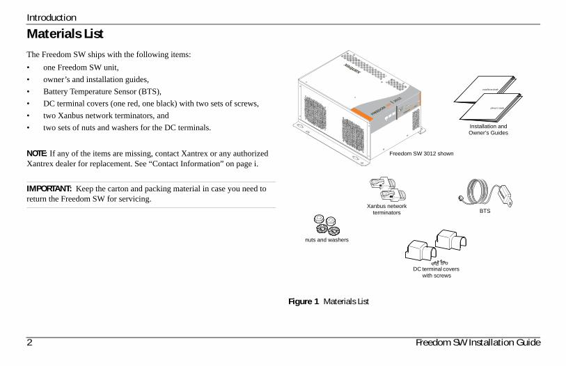
Materials ListThe Freedom SW ships with the following items:
• one Freedom SW unit,
• owner’s and installation guides,
• Battery Temperature Sensor (BTS),
• DC terminal covers (one red, one black) with two sets of screws,
• two Xanbus network terminators, and
• two sets of nuts and washers for the DC terminals.
NOTE: If any of the items are missing, contact Xantrex or any authorized Xantrex dealer for replacement. See “Contact Information” on page i.
IMPORTANT: Keep the carton and packing material in case you need to return the Freedom SW for servicing.
Figure 1 Materials List
FREEDOM SW 3012
FREEDOM SW 3012
CLEAR FA
ULT
RESET
INVERTER
ENABLE
INVERTER
ENABLED
AC IN
FAULT
GEN
SUPPORT
CHARGINGWARNING
BTS
DC terminal covers with screws
nuts and washers
Freedom SW 3012 shown
Installation and Owner’s Guides
Xanbus network terminators
2 Freedom SW Installation Guide
Thi
s gu
ide
for
use
by q
uali
fied
inst
alle
rs o
nly.
Installation Information
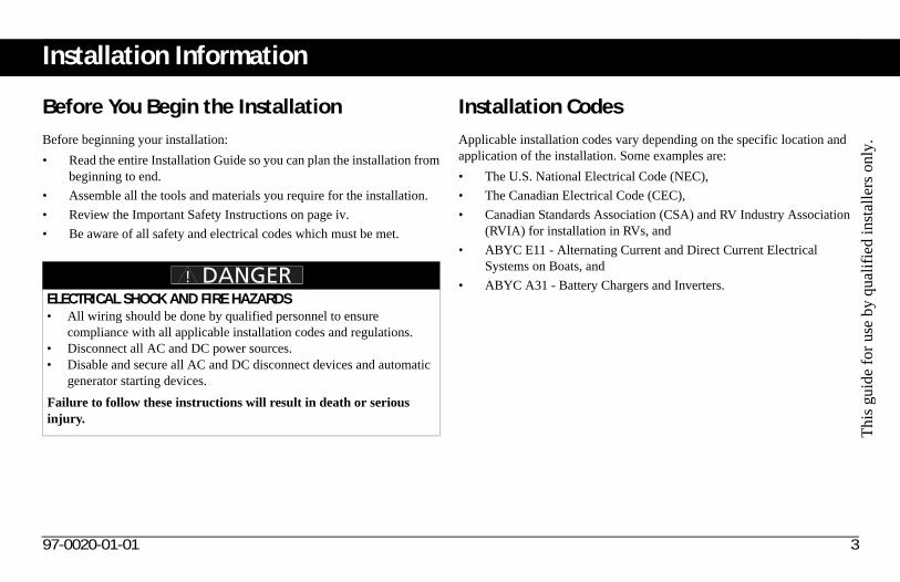
Before You Begin the InstallationBefore beginning your installation:
• Read the entire Installation Guide so you can plan the installation from beginning to end.
• Assemble all the tools and materials you require for the installation.
• Review the Important Safety Instructions on page iv.
• Be aware of all safety and electrical codes which must be met.
Installation CodesApplicable installation codes vary depending on the specific location and application of the installation. Some examples are:
• The U.S. National Electrical Code (NEC),
• The Canadian Electrical Code (CEC),
• Canadian Standards Association (CSA) and RV Industry Association (RVIA) for installation in RVs, and
• ABYC E11 - Alternating Current and Direct Current Electrical Systems on Boats, and
• ABYC A31 - Battery Chargers and Inverters.ELECTRICAL SHOCK AND FIRE HAZARDS• All wiring should be done by qualified personnel to ensure
compliance with all applicable installation codes and regulations.• Disconnect all AC and DC power sources. • Disable and secure all AC and DC disconnect devices and automatic
generator starting devices.
Failure to follow these instructions will result in death or serious injury.
97-0020-01-01 3
About the Xanbus System
Xanbus System
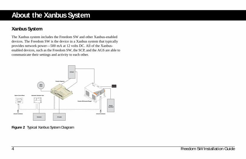
The Xanbus system includes the Freedom SW and other Xanbus-enabled devices. The Freedom SW is the device in a Xanbus system that typically provides network power—500 mA at 12 volts DC. All of the Xanbus-enabled devices, such as the Freedom SW, the SCP, and the AGS are able to communicate their settings and activity to each other.
Figure 2 Typical Xanbus System Diagram
Xanbus System Control Panel
Xanbus Automatic Generator Start
System Control Panel
network terminator network terminator
Automatic Generator Start
Freedom Sequence
Freedom SW Inverter/Charger
FREEDOM SW 3012
FREEDOM SW 3012
Inverter
Reset
Enable
Inverter
AC/
On
Charge Fault
Generator
ShorePower
AC Loads
AC Panel
BATTERY
Inverter Load Panel
4 Freedom SW Installation Guide
Thi
s gu
ide
for
use
by q
uali
fied
inst
alle
rs o
nly.
About the Xanbus System
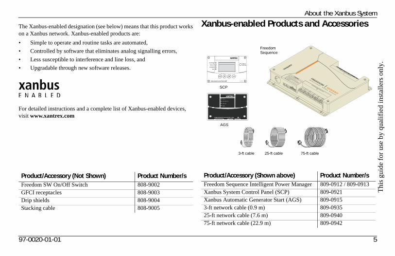
The Xanbus-enabled designation (see below) means that this product works on a Xanbus network. Xanbus-enabled products are:
• Simple to operate and routine tasks are automated,
• Controlled by software that eliminates analog signalling errors,
• Less susceptible to interference and line loss, and
• Upgradable through new software releases.
For detailed instructions and a complete list of Xanbus-enabled devices, visit www.xantrex.com
Xanbus-enabled Products and Accessories
Product/Accessory (Not Shown) Product Number/sFreedom SW On/Off Switch 808-9002GFCI receptacles 808-9003Drip shields 808-9004Stacking cable 808-9005
Product/Accessory (Shown above) Product Number/sFreedom Sequence Intelligent Power Manager 809-0912 / 809-0913Xanbus System Control Panel (SCP) 809-0921Xanbus Automatic Generator Start (AGS) 809-09153-ft network cable (0.9 m) 809-093525-ft network cable (7.6 m) 809-094075-ft network cable (22.9 m) 809-0942
Xanbus System Control Panel (SCP) FGA: 809-0921
AC In/Charge
Inverter On
Low Battery
Fault
STBY/ONFault Clear
TM
Enter Func
Freedom Sequence
SCP
AGS
25-ft cable 75-ft cable3-ft cable
97-0020-01-01 5
Planning the InstallationThis section provides information to help you plan for a basic installation of the Freedom SW.
As your system configuration is determined, record the details in “Information About Your System” in the Freedom SW Sine Wave Inverter/Charger Owner’s Guide.
Two Key Performance FactorsTwo key factors in particular will have a major impact on system performance.
Size and Length of DC Cables
To select the appropriate size and length of DC cables, see “DC Cabling” on page 16.
The DC cables should be as short as possible and large enough to handle the required current, in accordance with the electrical codes or regulations applicable to your installation. If there are long battery cables which are in excess of 10 feet each and not of sufficient size, the voltage drop across the cables will have a negative impact on overall system performance.
Mounting Location of the Freedom SW
To choose an appropriate location for mounting the inverter/charger, see “Step 1: Choosing a Location for the Inverter/Charger” on page 21.
6 Freedom SW Installation Guide
Thi
s gu
ide
for
use
by q
uali
fied
inst
alle
rs o
nly.
Planning Preparations
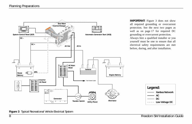
AC, DC, and Network ComponentsFor a successful installation, you need to plan for AC, DC, and network components of the power system. The AC and DC components are described in this section and illustrated in Figure 3 on page 8.
AC components include:
• AC Input for Dual AC Line Models, AC Input for Single AC Line Models
• AC Loads
• AC Disconnect and Over-Current Protection Device
• Distribution Panels
• AC Wiring
• AC Output Neutral Bonding
DC components include:
• Batteries
• DC Cabling
• DC Cabling
• DC Grounding
Network considerations for Freedom SW only include:
• Cables, connectors, network connectors, and terminators for the SCP and Automatic Generator Start, if installing.
Detailed information on planning and installing your network is available in the Xanbus System Installation Guide. Refer to the system guide to determine the type of network layout to install, as well as guidelines for installing the network. This guide is available for download at www.xantrex.com
97-0020-01-01 7
Planning Preparations
Figure 3 Typical Recreational Vehicle Electrical System
FREEDOM SW 3012
Inverter
Reset Enable
Inverter AC/
On Charge Fault
FREEDOM SW 3012
Non-Inverter Loads
Sine WaveInverter/Charger
System Control Panel (SCP) Automatic Generator Start (AGS)
Legend:Xanbus Network
AC OutDC +
DC –
HouseBattery
BTS
GeneratorTransfer Switch
AC In
AC MainPanel
InverterAC Panel
Isolator
Engine Battery
AlternatorUtility Power
RESET
TEST
ACDCLow Voltage DC
IMPORTANT: Figure 3 does not showall required grounding or overcurrentprotection. See the next two pages aswell as on page 17 for required DCgrounding or overcurrent protection. Always hire a qualified installer or youyourself must be one to ensure that allelectrical safety requirements are metbefore, during, and after installation.
8 Freedom SW Installation Guide
Thi
s gu
ide
for
use
by q
uali
fied
inst
alle
rs o
nly.
Planning Preparations
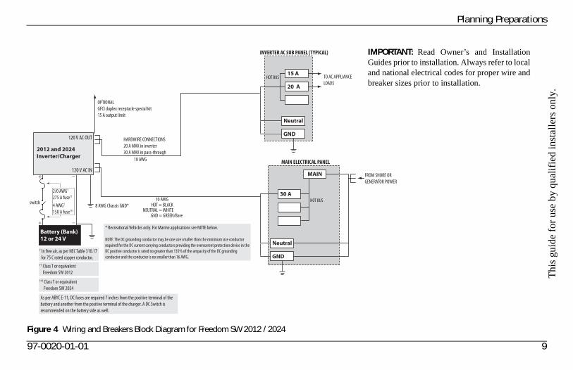
Figure 4 Wiring and Breakers Block Diagram for Freedom SW 2012 / 2024
2012 and 2024Inverter/Charger
120 V AC OUT
120 V AC IN
Battery (Bank)12 or 24 V
4 AWG†
150 A fuse†††
2/0 AWG†
275 A fuse††
8 AWG Chassis GND*switch
10 AWG
10 AWGHOT = BLACK
NEUTRAL = WHITEGND = GREEN/Bare
HOT BUS
HOT BUS TO AC APPLIANCE
LOADS
INVERTER AC SUB PANEL (TYPICAL)
MAIN ELECTRICAL PANEL
FROM SHORE OR
GENERATOR POWER
OPTIONAL
GFCI duplex receptacle special kit
15 A output limit
HARDWIRE CONNECTIONS
20 A MAX in inverter
30 A MAX in pass-through
Neutral
GND
15 A
20 A
Neutral
GND
30 A
MAIN
* Recreational Vehicles only. For Marine applications see NOTE below.
NOTE: The DC grounding conductor may be one size smaller than the minimum size conductor
required for the DC current carrying conductors providing the overcurrent protection device in the
DC positive conductor is rated no greater than 135% of the ampacity of the DC grounding
conductor and the conductor is no smaller than 16 AWG.
†† Class T or equivalent
Freedom SW 2012
† In free air, as per NEC Table 310.17
for 75 C rated copper conductor.
††† Class T or equivalent
Freedom SW 2024
As per ABYC E-11, DC fuses are required 7 inches from the positive terminal of the
battery and another from the positive terminal of the charger. A DC Switch is
recommended on the battery side as well.
IMPORTANT: Read Owner’s and InstallationGuides prior to installation. Always refer to localand national electrical codes for proper wire andbreaker sizes prior to installation.
97-0020-01-01 9
Planning Preparations
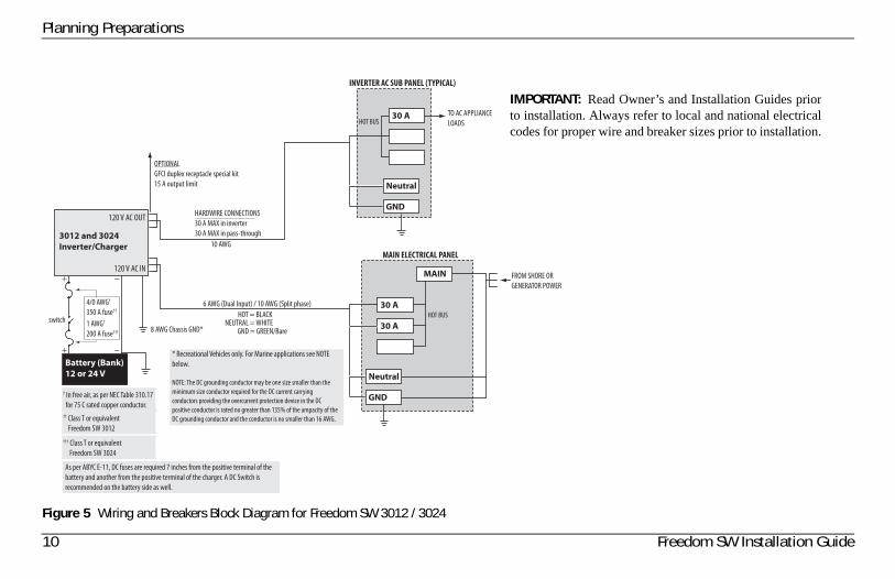
Figure 5 Wiring and Breakers Block Diagram for Freedom SW 3012 / 3024
3012 and 3024Inverter/Charger
120 V AC OUT
120 V AC IN
Battery (Bank)12 or 24 V
8 AWG Chassis GND*
10 AWG
6 AWG (Dual Input) / 10 AWG (Split phase)
HOT = BLACKNEUTRAL = WHITE
GND = GREEN/Bare
HOT BUS
HOT BUSTO AC APPLIANCE
LOADS
INVERTER AC SUB PANEL (TYPICAL)
MAIN ELECTRICAL PANEL
FROM SHORE OR
GENERATOR POWER
HARDWIRE CONNECTIONS
30 A MAX in inverter
30 A MAX in pass-through
Neutral
GND
30 A
Neutral
GND
30 A
30 A
MAIN
OPTIONAL
GFCI duplex receptacle special kit
15 A output limit
* Recreational Vehicles only. For Marine applications see NOTE
below.
NOTE: The DC grounding conductor may be one size smaller than the
minimum size conductor required for the DC current carrying
conductors providing the overcurrent protection device in the DC
positive conductor is rated no greater than 135% of the ampacity of the
DC grounding conductor and the conductor is no smaller than 16 AWG.
1 AWG†
200 A fuse†††
4/0 AWG†
350 A fuse††
†† Class T or equivalent
Freedom SW 3012
††† Class T or equivalent
Freedom SW 3024
† In free air, as per NEC Table 310.17
for 75 C rated copper conductor.
switch
As per ABYC E-11, DC fuses are required 7 inches from the positive terminal of the
battery and another from the positive terminal of the charger. A DC Switch is
recommended on the battery side as well.
IMPORTANT: Read Owner’s and Installation Guides priorto installation. Always refer to local and national electricalcodes for proper wire and breaker sizes prior to installation.
10 Freedom SW Installation Guide
Thi
s gu
ide
for
use
by q
uali
fied
inst
alle
rs o
nly.
97-0020-01-01 11
Planning Preparations
AC ComponentsNOTE: Unless otherwise referenced specifically by product name, the components refer to all models of Freedom SW inverter/chargers.
AC Input for Single AC Line Models
AC input (to a single AC line model such as Freedom SW 2012 inverter/charger) can be supplied from a single-phase 120-volt 60-Hz AC source such as the utility grid (power company), a generator, or the output of a transfer switch.
AC Input for Dual AC Line Models
AC inputs (to a dual AC line model such as Freedom SW 3012 inverter/charger) can be supplied from a split-phase or dual-input AC source such as the utility grid (power company), a generator, or the output of a transfer switch. The Freedom SW can be operated from the following types of 120 volt 60 Hz AC sources:
• Split phase: This source type has two lines, one neutral, and one ground. The two 120 volts AC lines are 180 degrees out of phase with each other, so that the two voltages total to 240 volts AC line to line. The voltage between each line and neutral is still 120 volts AC, and the voltage between the neutral and ground is approximately zero.
Because the two lines are out of phase, the currents from each line subtract in the neutral, and the neutral current will be approximately zero if the loads are equal. For example, if Line 1 is supplying 20 amps and Line 2 is supplying 15 amps, the current in the neutral will be 5 amps.
• Dual input: This source type has two line inputs, one neutral, and one ground. Unlike the split-phase type, the two lines are in phase (not out of phase), and must come from the same source. The voltage between the two lines is zero. The voltage between each line and the neutral is 120 volts AC, and the voltage between the neutral and ground is approximately zero.
Because the two lines are in phase, the currents from each line add together in the neutral. For example, if Line 1 is supplying 20 amps and Line 2 is supplying 15 amps, the current in the neutral will be 35 amps.
Planning Preparations
AC OutputThe output voltage on Freedom SW inverter/chargers is 120Vac. The AC output line configuration depends on the model.
• Single AC Line models have a Single Input and Single Output line(SI-SO) configuration.
• Dual AC Line models support Dual Input and Dual Output lines(DI-DO) configuration.
AC Loads
The Freedom SW is intended to power loads consisting of 120 volts AC appliances.
In Invert mode, the Freedom SW connects L1 and L2 output lines together to provide 120 volts AC to loads on either line. In AC Bypass mode, the source connected to the AC input is passed through to the load. Because of the way invert mode operates, only 120 volts AC appliances can be connected to the Freedom SW output.
AC Disconnect and Over-Current Protection Device
To meet CSA, UL, and electrical code requirements, and to protect system wiring, the AC inputs and outputs of the inverter/charger must be provided with overcurrent protection on both the AC input and output. This protection may be a circuit breaker or a fuse with a disconnect device (for simplicity the following refers to breakers). Refer to your applicable installation codes and the following requirements:
AC Input Protection
The breakers protecting the AC input of the Freedom SW must be approved for use on 120 volts AC branch circuits, and must be located in each Line. The breakers must be rated as shown below:
• Split-phase input: No more than 30 amps max in each line.
• Dual input: The neutral current in a dual-input system is the sum of the two line currents, and must be limited to 60 amps maximum to protect the transfer relay in the Freedom SW. Each breaker must not exceed 30 amps, and the total (sum) of the ratings of the two breakers must not exceed 60 amps.
AC Output Protection
The breaker between the Freedom SW AC output and the AC loads must be rated to protect the AC output wire size used. If the AC output wiring is based on the full 30-amp pass-through rating, then a 30-amp output breaker is acceptable. If the AC output wiring is smaller, then the breaker size will have to be smaller as well, in accordance with applicable electrical installation codes.
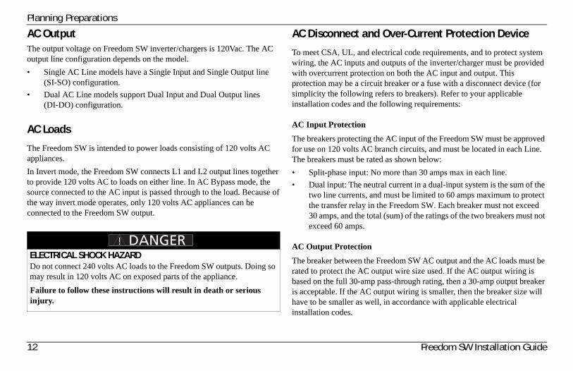
ELECTRICAL SHOCK HAZARDDo not connect 240 volts AC loads to the Freedom SW outputs. Doing so may result in 120 volts AC on exposed parts of the appliance.
Failure to follow these instructions will result in death or serious injury.
12 Freedom SW Installation Guide
Thi
s gu
ide
for
use
by q
uali
fied
inst
alle
rs o
nly.
Planning PreparationsGFCI Requirements
A GFCI (ground fault circuit interrupter) is a device that de energizes a circuit when a current to ground exceeds a specified value that is less than that required to open the circuit breaker. GFCIs are intended to protect people from electric shocks and are usually required in wet or damp locations.
Installation in recreational vehicles requires GFCI protection of certain branch circuits. Consult all applicable codes.
Tested GFCIs
Compliance with UL standards requires that Xantrex test and recommend specific GFCIs for use on the output of the inverter. Table 1 lists models that have been tested and will function properly when connected to the AC output of the Freedom SW.
Disconnect Devices
Each system requires a method of disconnecting the AC circuits. If the overcurrent protection device is a circuit breaker, it will also serve as the disconnect. If fuses are used, separate AC disconnect switches will be needed between the source and the fuses.
Distribution Panels
Some systems incorporate distribution panels both ahead of the inverter/charger (the AC source panel) and between the inverter/charger and the loads (the AC load panel). The AC source panel includes a main circuit breaker, which serves as overcurrent protection for the panel. Additional circuit breakers serve individual circuits, one of which serves the inverter/charger.
AC Wiring
Definition AC wiring includes input wiring (all the wires and connectors between the AC source and the inverter/charger input) and output wiring (all the wires between the inverter/charger and the AC load panels, circuit breakers, and loads).
Type The type of wiring required varies according to the electrical codes or regulations applicable to your installation. For RV applications, this may be solid wire in multi-conductor cables, but stranded wire is required if single conductors are used. All wiring must be rated 90 °C or higher.
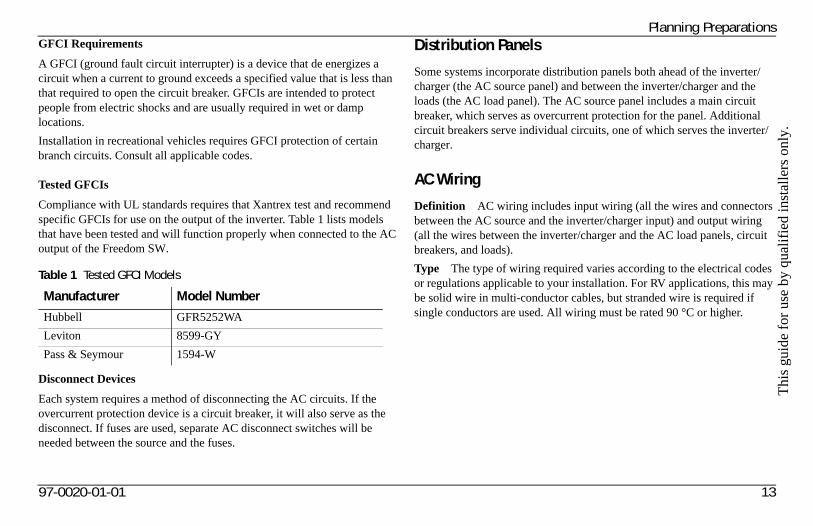
Table 1 Tested GFCI Models
Manufacturer Model Number
Hubbell GFR5252WA
Leviton 8599-GY
Pass & Seymour 1594-W
97-0020-01-01 13
Planning Preparations
Size of AC Input Wiring Wire size must be coordinated with the overcurrent protection provided ahead of the wire involved, in accordance with the electrical codes or regulations applicable to your installation.
Therefore, the wiring used between the AC input circuit breaker and the inverter/charger input must be sized to match the input breaker rating.
For dual input, the wire may be red or black; consult the documentation provided with the AC source (utility or generator).
Size of AC Output Wiring Wire size must be coordinated with the current the wiring will carry. This current may be determined by the 25-amp (Freedom SW 3012) and 20-amp (Freedom SW 2012) maximum inverter current, or by the bypass current, which is determined by the overcurrent protection provided ahead of the Freedom SW.
Some conditions for Freedom SW:
• If the input wiring is split-phase, the output wiring must be sized to coordinate with the breakers used on the input. Refer to your applicable installation codes.
• If the input wiring is dual-input and the output wiring is single-input, the following rules apply: If the input breaker on L1 is greater than 25 amps, the wire size must be coordinated for that amperage. If the input breaker on L1 is less than 25 amps, the wire size must be coordinated for 25 amps. The wire size must not be sized for anything lower than 25 amps.
• If both the input and the output wiring are dual-input, the output wiring for each line (L1 and L2) must be calculated separately, following these rules: If the input breaker on the specific line is greater than 25 amps, the wire size for that line and its neutral must be coordinated for that amperage. If the input breaker on the specific line is less than 25 amps, the wire size for that line and its neutral must be coordinated for 25 amps. The wire size must not be sized for anything lower than 25 amps.
Size of Wiring Downstream of the AC Output Breaker The wiring used between the AC output breaker and your loads must be sized to match the output breaker.
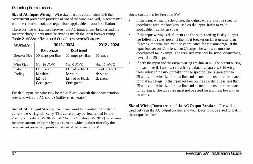
Table 2 AC Wire Size In and Out of the Inverter/Chargers
MODELS 3012 / 3024 2012 / 2024Split phase Dual input
Breaker Size Used
30 amps per line 30 amps per line 30 amps
Wire Size No. 10 AWG No. 6 AWG No. 10 AWGColor Coding
L1: black:N: whiteL2: redGnd: green
L1: red or blackN: whiteL2: red or blackGnd: green
L: red or blackN: whiteG: green
14 Freedom SW Installation Guide
Thi
s gu
ide
for
use
by q
uali
fied
inst
alle
rs o
nly.
Planning Preparations
AC Output Neutral Bonding
The AC source must have its neutral conductor bonded to ground.
Bonding system The Freedom SW provides a system that automatically connects the neutral conductor of the inverter’s AC output circuit to safety ground (“bonding” it) while the inverter/charger is inverting, and disconnects it (“unbonding” it) when the inverter/charger is connected to external AC power. This system is designed to conform to installation codes that require AC sources such as inverters and generators to have their neutral conductors tied to ground at the source of power in the same way that the neutral conductor from the utility is tied to ground. These same codes specify that the neutral can only be connected to ground in one place at any one time.
Suitability This automatic neutral-to-ground bonding system requires AC input sources with bonded neutral. This will be the case in most situations: in a utility feed, at an external AC hook-up, or a generator with a bonded neutral. If not, have an electrician look into bonding the source’s neutral to ground. See also “AC Input and Output Isolation” on page 26.
97-0020-01-01 15
Planning Preparations
DC Components
Batteries
The Freedom SW system requires a 12- or 24-volt (depending on the model), lead-acid deep-cycle battery or group of batteries to provide the DC current that the inverter/charger converts to AC power. The battery may be a flooded, gel, or AGM type.
See “Battery Information” on page 53 for information on:
• Estimating the battery size that will meet your requirements.
• Designing battery banks.
• Restrictions on the size of appliances.
For information on cabling and hooking up batteries, see “Battery Cabling and Hook-up Configurations” on page 57.
For detailed information about specific brands of batteries, you’ll need to consult individual battery manufacturers for this information.
DC Cabling
Definition DC cabling includes all of the cables and connectors between the batteries, the DC disconnect and overcurrent protection device, and the inverter/charger.
Type All installations require multi-strand insulated cables. The DC cables must be copper and must be rated 105 °C minimum.
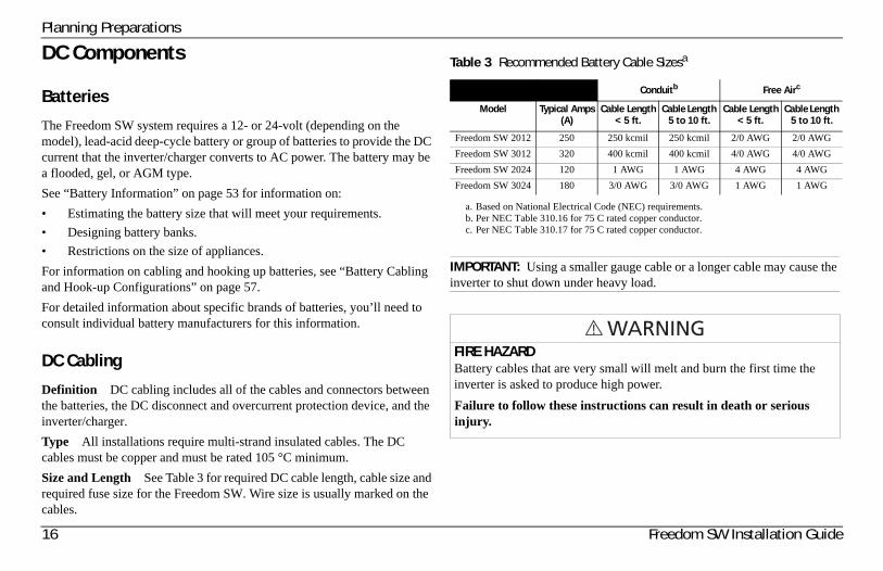
Size and Length See Table 3 for required DC cable length, cable size and required fuse size for the Freedom SW. Wire size is usually marked on the cables.
Table 3 Recommended Battery Cable Sizesa
a. Based on National Electrical Code (NEC) requirements.
Conduitb
b. Per NEC Table 310.16 for 75 C rated copper conductor.
Free Airc
c. Per NEC Table 310.17 for 75 C rated copper conductor.
Model Typical Amps(A)
Cable Length< 5 ft.
Cable Length 5 to 10 ft.
Cable Length< 5 ft.
Cable Length 5 to 10 ft.
Freedom SW 2012 250 250 kcmil 250 kcmil 2/0 AWG 2/0 AWG
Freedom SW 3012 320 400 kcmil 400 kcmil 4/0 AWG 4/0 AWG
Freedom SW 2024 120 1 AWG 1 AWG 4 AWG 4 AWG
Freedom SW 3024 180 3/0 AWG 3/0 AWG 1 AWG 1 AWG
IMPORTANT: Using a smaller gauge cable or a longer cable may cause the inverter to shut down under heavy load.
FIRE HAZARDBattery cables that are very small will melt and burn the first time the inverter is asked to produce high power.
Failure to follow these instructions can result in death or serious injury.
16 Freedom SW Installation Guide
Thi
s gu
ide
for
use
by q
uali
fied
inst
alle
rs o
nly.
97-0020-01-01 17
Planning Preparations
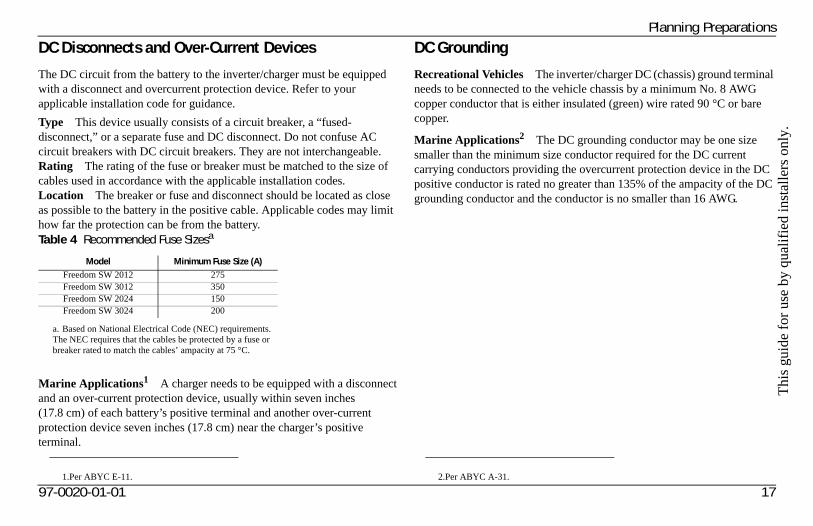
DC Disconnects and Over-Current Devices
The DC circuit from the battery to the inverter/charger must be equipped with a disconnect and overcurrent protection device. Refer to your applicable installation code for guidance.
Type This device usually consists of a circuit breaker, a “fused-disconnect,” or a separate fuse and DC disconnect. Do not confuse AC circuit breakers with DC circuit breakers. They are not interchangeable. Rating The rating of the fuse or breaker must be matched to the size of cables used in accordance with the applicable installation codes. Location The breaker or fuse and disconnect should be located as close as possible to the battery in the positive cable. Applicable codes may limit how far the protection can be from the battery.
Marine Applications1 A charger needs to be equipped with a disconnect and an over-current protection device, usually within seven inches (17.8 cm) of each battery’s positive terminal and another over-current protection device seven inches (17.8 cm) near the charger’s positive terminal.
DC Grounding
Recreational Vehicles The inverter/charger DC (chassis) ground terminal needs to be connected to the vehicle chassis by a minimum No. 8 AWG copper conductor that is either insulated (green) wire rated 90 °C or bare copper.
Marine Applications2 The DC grounding conductor may be one size smaller than the minimum size conductor required for the DC current carrying conductors providing the overcurrent protection device in the DC positive conductor is rated no greater than 135% of the ampacity of the DC grounding conductor and the conductor is no smaller than 16 AWG.
Table 4 Recommended Fuse Sizesa
a. Based on National Electrical Code (NEC) requirements. The NEC requires that the cables be protected by a fuse or breaker rated to match the cables’ ampacity at 75 °C.
Model Minimum Fuse Size (A)Freedom SW 2012 275Freedom SW 3012 350Freedom SW 2024 150Freedom SW 3024 200
1.Per ABYC E-11. 2.Per ABYC A-31.
Planning Preparations
Unpacking and Inspecting the Freedom SW Inverter/Charger
To unpack and inspect:
1. Unpack the unit and check the materials list. If anything is missing from the shipping box, contact Xantrex Customer Service. See “Contact Information” on page i.
2. Record the serial number of the Freedom SW and other purchase information in the Warranty section of the Freedom SW Sine Wave Inverter/Charger Owner’s Guide. You will be asked for this product information if you need to call Xantrex Customer Service.
3. Save your purchase receipt to use as proof-of-purchase. This receipt is required if the inverter/charger should need warranty service.
4. Save the original shipping carton and packing materials. If the inverter/charger needs to be returned for service, it should be shipped in the original carton. Packing the Freedom SW in the original shipping carton is also a good way to protect the inverter/charger if it ever needs to be moved.
HEAVY LOADThe Freedom SW Inverter/Charger is heavy (see “Inverter/Charger Physical Specifications” on page 52). The unit is too heavy for one person to safely lift and mount. Xantrex recommends that two people lift and mount the unit. Always use proper lifting techniques during installation to prevent personal injury.
Failure to follow these instructions can result in minor or moderate injury.
IMPORTANT: Keep the carton and packing material in case you need to return the Freedom SW for servicing.
18 Freedom SW Installation Guide
Thi
s gu
ide
for
use
by q
uali
fied
inst
alle
rs o
nly.
Planning Preparations
Installation Tools and Materials
Tools
You will need the following tools to install the Freedom SW and the battery temperature sensor.
❐ Wire stripper
❐ Crimping tools for fastening lugs and terminals on DC cables
❐ Phillips screwdriver: #2
❐ Slot screwdriver (¼" wide blade max.)
❐ Needle-nose pliers
❐ Wrench for DC terminals: 9/16"
Materials
You will need the following materials to complete your installation:
❐ Strain-relief clamp(s) for AC cables (not provided): 3/4" and/or 1"
❐ DC battery cables sized according to Table 3 on page 16
❐ Terminals and/or crimp connectors for DC cables (for 3/8" stud size)
❐ Copper wire for DC grounding: No. 8 AWG. See “DC Grounding” on page 17
❐ Terminal or crimp connector for DC grounding cable (for 1/4" stud size)
❐ AC and DC disconnect switches and overcurrent protective devices and connectors as required. See page 16.
❐ AC output and input wire. See Figure 3 on page 8.
❐ If the AC ground wire is stranded, each ground wire requires a ring terminal
❐ Six 1/4"–20 1.25" length steel screws or bolts to mount the unit
NOTE: For a list of tools and materials required to install the network, refer to the Xanbus System Installation Guide, which is available for download at www.xantrex.com.
97-0020-01-01 19
Installing the Inverter/Charger
OverviewThis section provides detailed information on installing the Freedom SW. The overall procedure is divided into eight steps:
Step 1: Choosing a Location for the Inverter/Charger on page 21,
Step 2: Mounting the Inverter/Charger on page 23,
Step 3: Connecting the AC Input and AC Output Wires on page 26,
Step 4: Connecting the DC Cables on page 30,
Step 5: Connecting the Battery Temperature Sensor (BTS) on page 35,
Step 6: Connecting to the Network on page 39,
Step 7: Performing Checks Prior to Initial Start-Up on page 40, and
Step 8: Testing Your Installation on page 41.
20 Freedom SW Installation Guide
Thi
s gu
ide
for
use
by q
uali
fied
inst
alle
rs o
nly.
97-0020-01-01 21
Installing the Inverter/Charger
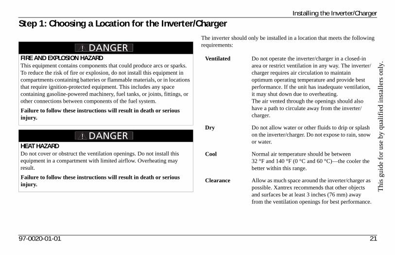
Step 1: Choosing a Location for the Inverter/ChargerThe inverter should only be installed in a location that meets the following requirements:
FIRE AND EXPLOSION HAZARDThis equipment contains components that could produce arcs or sparks. To reduce the risk of fire or explosion, do not install this equipment in compartments containing batteries or flammable materials, or in locations that require ignition-protected equipment. This includes any space containing gasoline-powered machinery, fuel tanks, or joints, fittings, or other connections between components of the fuel system.
Failure to follow these instructions will result in death or serious injury.
HEAT HAZARDDo not cover or obstruct the ventilation openings. Do not install this equipment in a compartment with limited airflow. Overheating may result.
Failure to follow these instructions will result in death or serious injury.
Ventilated Do not operate the inverter/charger in a closed-in area or restrict ventilation in any way. The inverter/charger requires air circulation to maintain optimum operating temperature and provide best performance. If the unit has inadequate ventilation, it may shut down due to overheating. The air vented through the openings should also have a path to circulate away from the inverter/charger.
Dry Do not allow water or other fluids to drip or splash on the inverter/charger. Do not expose to rain, snow or water.
Cool Normal air temperature should be between 32 °F and 140 °F (0 °C and 60 °C)—the cooler the better within this range.
Clearance Allow as much space around the inverter/charger as possible. Xantrex recommends that other objects and surfaces be at least 3 inches (76 mm) away from the ventilation openings for best performance.
Installing the Inverter/Charger
Safe Locate the inverter/charger away from battery in a separate well ventilated compartment. Do not install the inverter/charger in any compartment containing flammable gases or liquids like gasoline.
Close to battery compartment
The length and size of your DC cables will affect performance. Use the DC cables recommended in Table 3 on page 16. The unit should not be installed in the battery compartment due to the possible presence of explosive hydrogen gas from the batteries.
Protected from battery acid and gases
Never place the inverter/charger directly above the batteries—gases from battery will corrode and damage the inverter/charger. If the inverter/charger is installed in a compartment above the batteries, make sure there is a solid, gas-impermeable wall dividing the two compartments. Never allow battery acid to drip on the inverter/charger or its wiring when filling the batteries or reading their specific gravity.
Orientation To meet regulatory requirements, the Freedom SW must be mounted in one of the approved mounting orientations. See Figure 6 on page 24.
22 Freedom SW Installation Guide
Thi
s gu
ide
for
use
by q
uali
fied
inst
alle
rs o
nly.
Installing the Inverter/Charger
Step 2: Mounting the Inverter/Charger
Considerations
Before mounting the Freedom SW, take the following two factors into account.
1. The weight of the inverter/charger requires two people to install it.
2. Mounting considerations are shown in Figure 6 on page 24.
The Freedom SW dimensions and location of the mounting holes are provided in Figure 6 on page 24.
Mount your inverter/charger before you connect any wires or cables.
To mount the inverter/charger:
1. Remove the inverter/charger from its shipping container.
2. Verify that all components are present.
3. Select an appropriate mounting location and orientation. To meet regulatory requirements, the Freedom SW must be mounted in one of the orientations shown in Figure 6 on page 24.
4. Mark the position of the mounting holes.
5. Pilot drill the six mounting holes.
6. Fasten the inverter/charger to the mounting surface with six 1/4"–20 steel screws or bolts.
HEAVY LOADThe Freedom SW Inverter/Charger is heavy (see “Inverter/Charger Physical Specifications” on page 52). The unit is too heavy for one person to safely lift and mount. Xantrex recommends that two people lift and mount the unit. Always use proper lifting techniques during installation to prevent personal injury.
Failure to follow these instructions can result in minor or moderate injury.
97-0020-01-01 23
Installing the Inverter/Charger
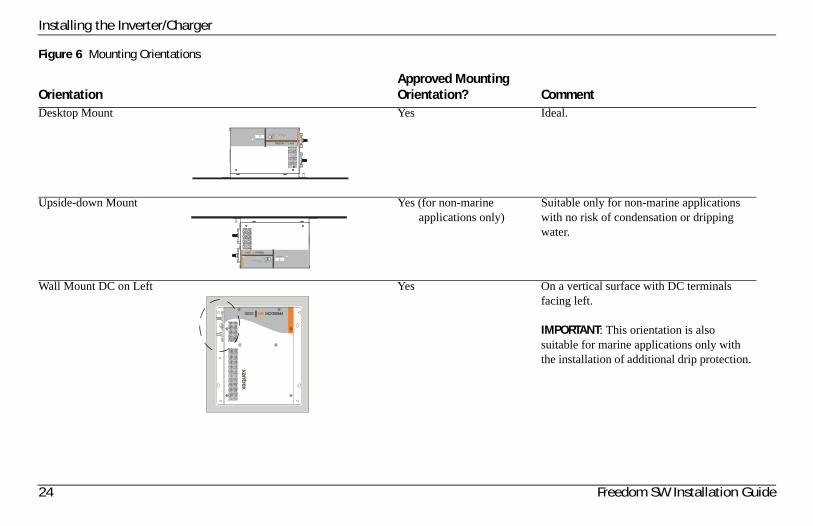
Figure 6 Mounting Orientations
OrientationApproved Mounting Orientation? Comment
Desktop Mount Yes Ideal.
Upside-down Mount Yes (for non-marine applications only)
Suitable only for non-marine applications with no risk of condensation or dripping water.
Wall Mount DC on Left Yes On a vertical surface with DC terminals facing left.
IMPORTANT: This orientation is also suitable for marine applications only with the installation of additional drip protection.
FREEDOM SW 3000
Inverter Reset Enable Inverter AC/
On Charge Fault
Xanbus Interface
FREEDOM SW 3000
Inverter Reset Enable Inverter AC/
On Charge Fault
Xanbus Interface
MODEERF SW 0003
24 Freedom SW Installation Guide
Thi
s gu
ide
for
use
by q
uali
fied
inst
alle
rs o
nly.
97-0020-01-01 25
Installing the Inverter/Charger
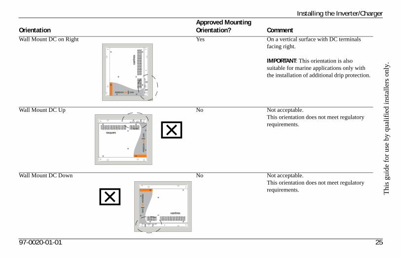
Wall Mount DC on Right Yes On a vertical surface with DC terminals facing right.
IMPORTANT: This orientation is also suitable for marine applications only with the installation of additional drip protection.
Wall Mount DC Up No Not acceptable. This orientation does not meet regulatory requirements.
Wall Mount DC Down No Not acceptable. This orientation does not meet regulatory requirements.
OrientationApproved Mounting Orientation? Comment
MODEERF SW 0003
MO
DEERF S
W
0003
MO
DEER
F SW
00
03
Installing the Inverter/Charger
Step 3: Connecting the AC Input and AC Output Wires
General AC Wiring Considerations
AC and DC Wiring Separation Do not mix AC and DC wiring in the same conduit or panel. Consult the applicable installation code for details about DC wiring and AC wiring in vicinity to each other.
AC Input and Output Isolation The AC input and output circuits of this inverter/charger are isolated from each other when in invert mode to ensure safe operation. This isolation must be maintained in the installation, by being sure not to connect AC input and output wiring to a common point. For example, do not route the AC input and output neutrals to a common neutral bus. It is highly recommended to use a separate inverter load panel to distribute power to inverter loads. All wiring to this panel must be through the inverter/charger and none to the main panel upstream of the inverter/charger.
IMPORTANT: wiring the output inverter to back to the main panel could result in ground bonding to occur in multiple locations in contravention of applicable wiring codes and may result in nuisance tripping of Ground fault protection equipment. All wiring must be performed by a qualified electrician.
AC Wiring Compartment For your reference, the AC wiring compartment is shown in Figure 7 on page 27.
AC Knockouts There are two dual 1.0"/ 3/4" trade-size knockouts on the side panel for AC wiring. Use the same trade size of strain relief as the trade size of the knockout(s) you are using.
AC Wiring Terminals The AC wiring terminals accept cables of a specific size. See “AC Wiring” on page 13 for required sizes.
FIRE, ELECTRICAL SHOCK, AND ENERGY HAZARDSMake sure wiring being connected to the inverter/charger is disconnected (physically or by opening the breaker) from all electrical sources before handling. All wiring must be done in accordance with local and national electrical wiring codes.
Failure to follow these instructions will result in death or serious injury.
26 Freedom SW Installation Guide
Thi
s gu
ide
for
use
by q
uali
fied
inst
alle
rs o
nly.
Installing the Inverter/Charger
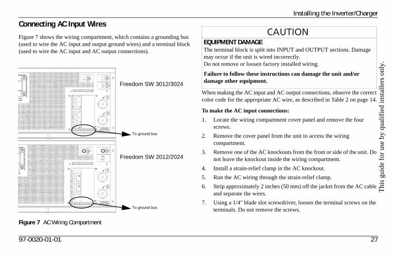
Connecting AC Input Wires
Figure 7 shows the wiring compartment, which contains a grounding bus (used to wire the AC input and output ground wires) and a terminal block (used to wire the AC input and AC output connections).
When making the AC input and AC output connections, observe the correct color code for the appropriate AC wire, as described in Table 2 on page 14.
To make the AC input connections:
1. Locate the wiring compartment cover panel and remove the four screws.
2. Remove the cover panel from the unit to access the wiring compartment.
3. Remove one of the AC knockouts from the front or side of the unit. Do not leave the knockout inside the wiring compartment.
4. Install a strain-relief clamp in the AC knockout.
5. Run the AC wiring through the strain-relief clamp.
6. Strip approximately 2 inches (50 mm) off the jacket from the AC cable and separate the wires.
7. Using a 1/4" blade slot screwdriver, loosen the terminal screws on the terminals. Do not remove the screws.
Figure 7 AC Wiring Compartment
BATTERY POLARITY W
ILL CAUSE DAM
AGE TO
UNIT.
WIRING BOX COVER MUST BE IN PLACE DURINGOPERATION TO REDUCE RISK OF INJURY TO PERSONS.
30ACHARG
ERAC IN
PUT
20AIN
VERTERAC O
UTPU
T
ACIN
ACOUT
AC GROUNDS(BEHIND COVER)
RECT BATTERY POLARITY W
ILL CAUSE DAM
AGE TO
UNIT.
WIRING BOX COVER MUST BE IN PLACE DURINGOPERATION TO REDUCE RISK OF INJURY TO PERSONS.
30ACHARG
ERAC IN
PUT 1
30APASS THRUAC IN
PUT 2
30AIN
VERTERAC O
UTPUT
ACIN
ACOUT
AC GROUNDS(BEHIND COVER)
Freedom SW 3012/3024
Freedom SW 2012/2024
To ground bus
To ground bus
EQUIPMENT DAMAGEThe terminal block is split into INPUT and OUTPUT sections. Damage may occur if the unit is wired incorrectly.Do not remove or loosen factory installed wiring.
Failure to follow these instructions can damage the unit and/or damage other equipment.
97-0020-01-01 27
Installing the Inverter/Charger
8. Connect the line and neutral wires to the input terminals (labeled AC Input on the terminal block, Figure 7 on page 27).
Freedom SW 3012/3024:Connect Line 1 to L1, Neutral to N, Line 2 to L2.
Freedom SW 2012/2024:Connect Line to L, Neutral to N, Ground to G.
9. Tighten the terminal screws. Leave some slack wire inside the wiring box.
10. Connect the ground wires to a free position on the ground bus, Figure 7 on page 27. If solid ground wire is being used, the wire can be connected directly under the screw heads. If stranded ground wire is being used, ring terminals must also be used.
11. Secure the strain-relief clamp on the AC input cable jacket.
28 Freedom SW Installation Guide
Thi
s gu
ide
for
use
by q
uali
fied
inst
alle
rs o
nly.
Installing the Inverter/Charger
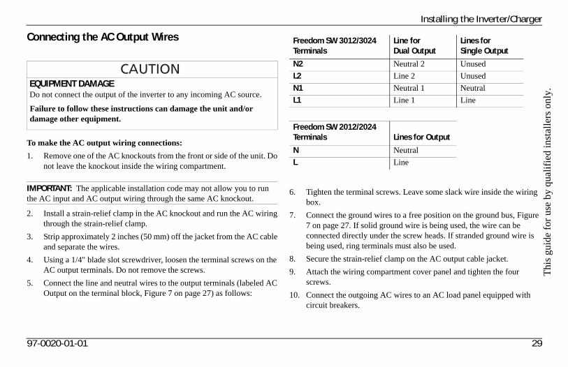
Connecting the AC Output Wires
To make the AC output wiring connections:
1. Remove one of the AC knockouts from the front or side of the unit. Do not leave the knockout inside the wiring compartment.
2. Install a strain-relief clamp in the AC knockout and run the AC wiring through the strain-relief clamp.
3. Strip approximately 2 inches (50 mm) off the jacket from the AC cable and separate the wires.
4. Using a 1/4" blade slot screwdriver, loosen the terminal screws on the AC output terminals. Do not remove the screws.
5. Connect the line and neutral wires to the output terminals (labeled AC Output on the terminal block, Figure 7 on page 27) as follows:
6. Tighten the terminal screws. Leave some slack wire inside the wiring box.
7. Connect the ground wires to a free position on the ground bus, Figure 7 on page 27. If solid ground wire is being used, the wire can be connected directly under the screw heads. If stranded ground wire is being used, ring terminals must also be used.
8. Secure the strain-relief clamp on the AC output cable jacket.
9. Attach the wiring compartment cover panel and tighten the four screws.
10. Connect the outgoing AC wires to an AC load panel equipped with circuit breakers.
EQUIPMENT DAMAGEDo not connect the output of the inverter to any incoming AC source.
Failure to follow these instructions can damage the unit and/or damage other equipment.
IMPORTANT: The applicable installation code may not allow you to run the AC input and AC output wiring through the same AC knockout.
Freedom SW 3012/3024 Terminals
Line for Dual Output
Lines for Single Output
N2 Neutral 2 Unused
L2 Line 2 Unused
N1 Neutral 1 Neutral
L1 Line 1 Line
Freedom SW 2012/2024 Terminals Lines for Output
N Neutral
L Line
97-0020-01-01 29
Installing the Inverter/Charger
Step 4: Connecting the DC Cables
DC Connection Precautions
Recommended Cable Sizes and Lengths and Fuse Size
For recommended DC cables and fuse sizes, see Table 3 and Table 4 on page 17.
Preparing the Cables
To prepare the DC cables:
1. Cut the negative and positive cables to the required length. Strip off enough insulation so you can install the terminals you will be using.
Xantrex recommends the use of crimp connectors. The connector should be designed for a 3/8" stud size to connect to the Freedom SW. If a crimp connector is used, it should be crimped using the tool indicated by the connector manufacturer.
2. Cut the DC ground cable to the required length. Strip off enough insulation so you can install the terminals you will be using.
Xantrex recommends the use of crimp connectors. The connector should be designed for a 1/4" stud size to connect to the Freedom SW. If a crimp connector is used, it should be crimped using the tool indicated by the connector manufacturer.
3. Attach the connectors to the ends of both cables. Make sure no stray wire strands protrude from the connectors.
ELECTRICAL SHOCK HAZARDConnect and disconnect DC wiring only after opening the disconnect switches or breakers at all AC and DC sources.
Failure to follow these instructions will result in death or serious injury.
30 Freedom SW Installation Guide
Thi
s gu
ide
for
use
by q
uali
fied
inst
alle
rs o
nly.
Installing the Inverter/Charger
Guidelines for Routing the DC Cables
Follow these guidelines to ensure maximum performance.
• Do not attempt to use the chassis in place of the battery negative connection for grounding. The inverter requires a reliable return path directly to the battery.
• To reduce the chance of radio frequency interference, keep the positive and negative cables close together—ideally, held together by straps, loom, or insulated clamps at regular intervals.
• To ensure maximum performance from the inverter/charger, do not route your DC cables through a DC distribution panel, battery isolator, or other device that will cause additional voltage drops. The exception is the DC fuse and Disconnect or the DC circuit breaker which is required at the battery to protect the DC wiring.
• To help avoid damage caused by reverse polarity battery connection, it is a good idea to mark each end of each cable to identify it as a positive (red) or negative (black) cable before routing the wiring.
ELECTRICAL SHOCK AND FIRE HAZARDRoute the cables away from sharp edges that might damage the insulation. Avoid sharp bends in the cable.
Failure to follow these instructions will result in death or serious injury.
97-0020-01-01 31
Installing the Inverter/Charger
Connecting the DC Cables to the Inverter/Charger
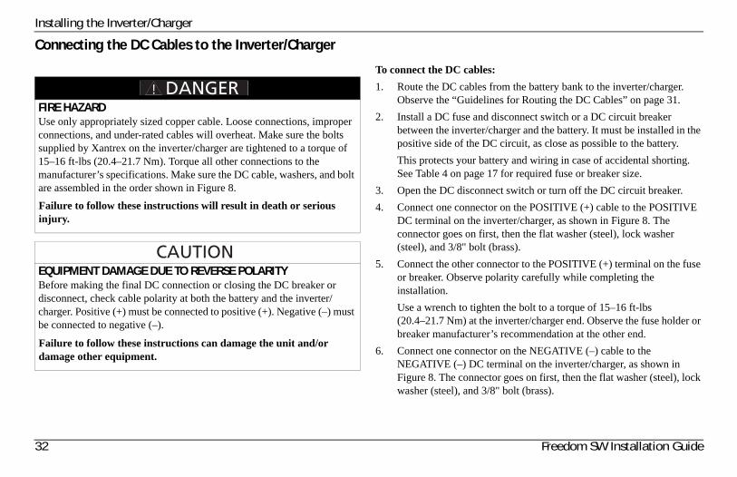
To connect the DC cables:
1. Route the DC cables from the battery bank to the inverter/charger. Observe the “Guidelines for Routing the DC Cables” on page 31.
2. Install a DC fuse and disconnect switch or a DC circuit breaker between the inverter/charger and the battery. It must be installed in the positive side of the DC circuit, as close as possible to the battery.
This protects your battery and wiring in case of accidental shorting. See Table 4 on page 17 for required fuse or breaker size.
3. Open the DC disconnect switch or turn off the DC circuit breaker.
4. Connect one connector on the POSITIVE (+) cable to the POSITIVE DC terminal on the inverter/charger, as shown in Figure 8. The connector goes on first, then the flat washer (steel), lock washer (steel), and 3/8" bolt (brass).
5. Connect the other connector to the POSITIVE (+) terminal on the fuse or breaker. Observe polarity carefully while completing the installation.
Use a wrench to tighten the bolt to a torque of 15–16 ft-lbs (20.4–21.7 Nm) at the inverter/charger end. Observe the fuse holder or breaker manufacturer’s recommendation at the other end.
6. Connect one connector on the NEGATIVE (–) cable to the NEGATIVE (–) DC terminal on the inverter/charger, as shown in Figure 8. The connector goes on first, then the flat washer (steel), lock washer (steel), and 3/8" bolt (brass).
FIRE HAZARDUse only appropriately sized copper cable. Loose connections, improper connections, and under-rated cables will overheat. Make sure the bolts supplied by Xantrex on the inverter/charger are tightened to a torque of 15–16 ft-lbs (20.4–21.7 Nm). Torque all other connections to the manufacturer’s specifications. Make sure the DC cable, washers, and bolt are assembled in the order shown in Figure 8.
Failure to follow these instructions will result in death or serious injury.
EQUIPMENT DAMAGE DUE TO REVERSE POLARITYBefore making the final DC connection or closing the DC breaker or disconnect, check cable polarity at both the battery and the inverter/charger. Positive (+) must be connected to positive (+). Negative (–) must be connected to negative (–).
Failure to follow these instructions can damage the unit and/or damage other equipment.
32 Freedom SW Installation Guide
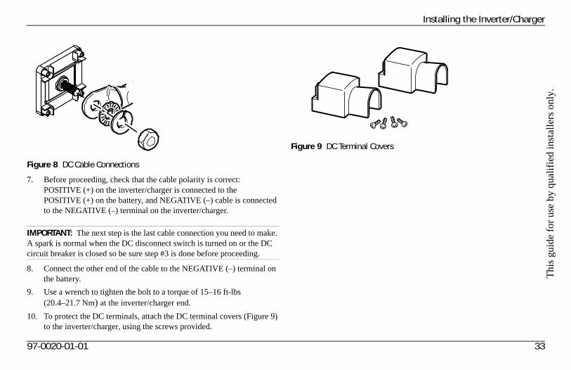
Thi
s gu
ide
for
use
by q
uali
fied
inst
alle
rs o
nly.
Installing the Inverter/Charger
7. Before proceeding, check that the cable polarity is correct: POSITIVE (+) on the inverter/charger is connected to the POSITIVE (+) on the battery, and NEGATIVE (–) cable is connected to the NEGATIVE (–) terminal on the inverter/charger.
8. Connect the other end of the cable to the NEGATIVE (–) terminal on the battery.
9. Use a wrench to tighten the bolt to a torque of 15–16 ft-lbs (20.4–21.7 Nm) at the inverter/charger end.
10. To protect the DC terminals, attach the DC terminal covers (Figure 9) to the inverter/charger, using the screws provided.
Figure 8 DC Cable Connections
IMPORTANT: The next step is the last cable connection you need to make. A spark is normal when the DC disconnect switch is turned on or the DC circuit breaker is closed so be sure step #3 is done before proceeding.
Figure 9 DC Terminal Covers
97-0020-01-01 33
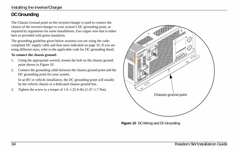
Installing the Inverter/Charger
DC Grounding
The Chassis Ground point on the inverter/charger is used to connect the chassis of the inverter/charger to your system’s DC grounding point, as required by regulations for some installations. Use copper wire that is either bare or provided with green insulation.
The grounding guideline given below assumes you are using the code-compliant DC supply cable and fuse sizes indicated on page 16. If you are using different sizes, refer to the applicable code for DC grounding detail.
To connect the chassis ground:
1. Using the appropriate wrench, loosen the bolt on the chassis ground point shown in Figure 10.
2. Connect the grounding cable between the chassis ground point and the DC grounding point for your system.
In an RV or vehicle installation, the DC grounding point will usually be the vehicle chassis or a dedicated chassis ground bus.
3. Tighten the screw to a torque of 1.0–1.25 ft-lbs (1.47–1.7 Nm).
Figure 10 DC Wiring and DC Grounding
DOM SW 3012
rter AC/n Charge Fault
012
Chassis ground point
34 Freedom SW Installation Guide
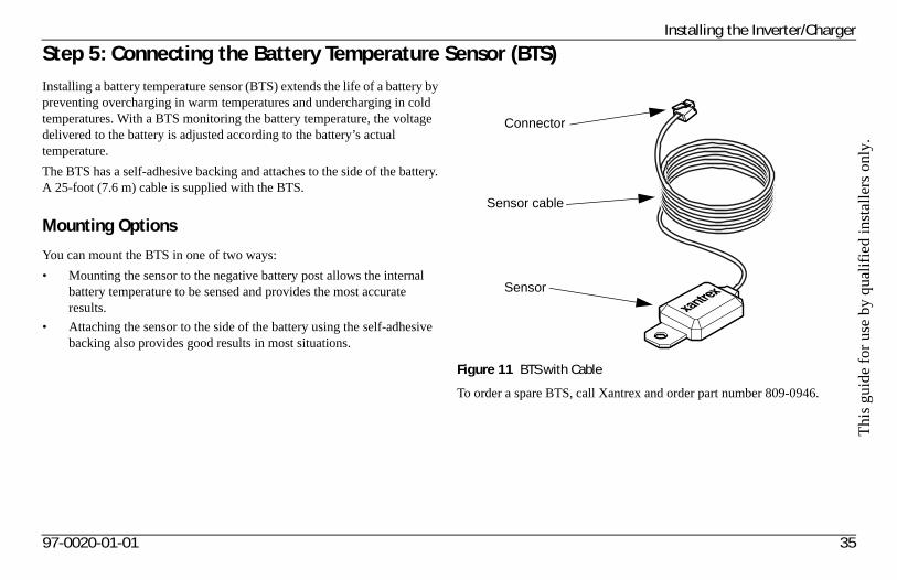
Thi
s gu
ide
for
use
by q
uali
fied
inst
alle
rs o
nly.
Installing the Inverter/Charger
Step 5: Connecting the Battery Temperature Sensor (BTS)Installing a battery temperature sensor (BTS) extends the life of a battery by preventing overcharging in warm temperatures and undercharging in cold temperatures. With a BTS monitoring the battery temperature, the voltage delivered to the battery is adjusted according to the battery’s actual temperature.
The BTS has a self-adhesive backing and attaches to the side of the battery. A 25-foot (7.6 m) cable is supplied with the BTS.
Mounting Options
You can mount the BTS in one of two ways:
• Mounting the sensor to the negative battery post allows the internal battery temperature to be sensed and provides the most accurate results.
• Attaching the sensor to the side of the battery using the self-adhesive backing also provides good results in most situations.
To order a spare BTS, call Xantrex and order part number 809-0946.
Figure 11 BTS with Cable
Connector
Sensor cable
Sensor
97-0020-01-01 35
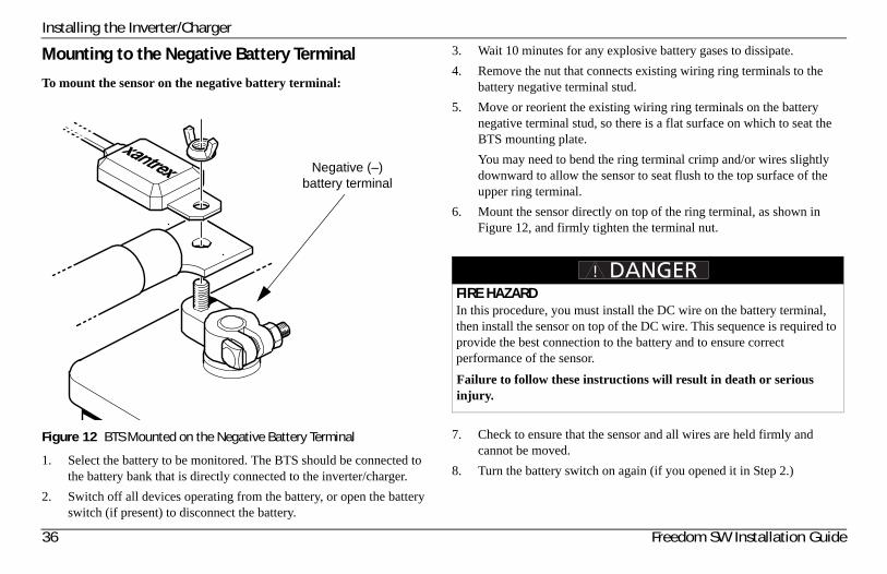
Installing the Inverter/Charger
Mounting to the Negative Battery Terminal
To mount the sensor on the negative battery terminal:
1. Select the battery to be monitored. The BTS should be connected to the battery bank that is directly connected to the inverter/charger.
2. Switch off all devices operating from the battery, or open the battery switch (if present) to disconnect the battery.
3. Wait 10 minutes for any explosive battery gases to dissipate.
4. Remove the nut that connects existing wiring ring terminals to the battery negative terminal stud.
5. Move or reorient the existing wiring ring terminals on the battery negative terminal stud, so there is a flat surface on which to seat the BTS mounting plate.
You may need to bend the ring terminal crimp and/or wires slightly downward to allow the sensor to seat flush to the top surface of the upper ring terminal.
6. Mount the sensor directly on top of the ring terminal, as shown in Figure 12, and firmly tighten the terminal nut.
7. Check to ensure that the sensor and all wires are held firmly and cannot be moved.
8. Turn the battery switch on again (if you opened it in Step 2.)
Figure 12 BTS Mounted on the Negative Battery Terminal
Negative (–) battery terminal
FIRE HAZARDIn this procedure, you must install the DC wire on the battery terminal, then install the sensor on top of the DC wire. This sequence is required to provide the best connection to the battery and to ensure correct performance of the sensor.
Failure to follow these instructions will result in death or serious injury.
36 Freedom SW Installation Guide
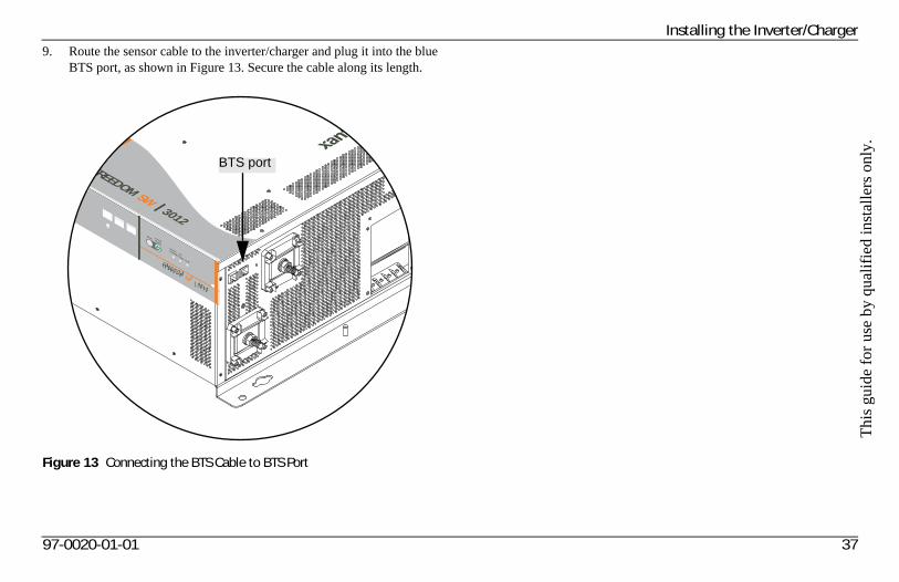
Thi
s gu
ide
for
use
by q
uali
fied
inst
alle
rs o
nly.
Installing the Inverter/Charger9. Route the sensor cable to the inverter/charger and plug it into the blue
BTS port, as shown in Figure 13. Secure the cable along its length.
Figure 13 Connecting the BTS Cable to BTS Port
FREEDOM SW 3012
Inverter
Reset Enable
Inverter AC/
Enabled Charge Fault
FREEDOM SW 3012
BTS port
97-0020-01-01 37
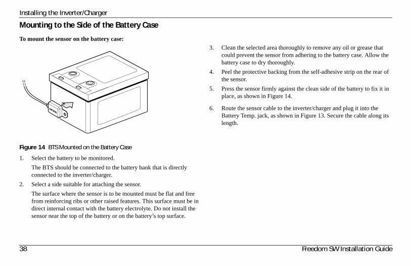
Installing the Inverter/Charger
Mounting to the Side of the Battery Case
To mount the sensor on the battery case:
1. Select the battery to be monitored.
The BTS should be connected to the battery bank that is directly connected to the inverter/charger.
2. Select a side suitable for attaching the sensor.
The surface where the sensor is to be mounted must be flat and free from reinforcing ribs or other raised features. This surface must be in direct internal contact with the battery electrolyte. Do not install the sensor near the top of the battery or on the battery’s top surface.
3. Clean the selected area thoroughly to remove any oil or grease that could prevent the sensor from adhering to the battery case. Allow the battery case to dry thoroughly.
4. Peel the protective backing from the self-adhesive strip on the rear of the sensor.
5. Press the sensor firmly against the clean side of the battery to fix it in place, as shown in Figure 14.
6. Route the sensor cable to the inverter/charger and plug it into the Battery Temp. jack, as shown in Figure 13. Secure the cable along its length.
Figure 14 BTS Mounted on the Battery Case
38 Freedom SW Installation Guide
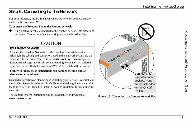
Thi
s gu
ide
for
use
by q
uali
fied
inst
alle
rs o
nly.
Installing the Inverter/Charger
Step 6: Connecting to the Network For your reference, Figure 15 shows where the network connections are made on the Freedom SW.
To connect the Freedom SW to the Xanbus network:
◆ Plug a network cable connected to the Xanbus network into either one of the two Xanbus Interface network ports on the Freedom SW.
Detailed information on planning and installing your network is available in the Xanbus System Installation Guide. Refer to the this guide to determine the type of network layout to install, as well as guidelines for installing the network.
The Xanbus System Installation Guide is available for download atwww. xantrex.com
EQUIPMENT DAMAGEConnect the Freedom SW only to other Xanbus compatible devices.Although the cabling and connectors used in this network system are the same as Ethernet connectors, this network is not an Ethernet system. Equipment damage may result from attempting to connect two different systems. Do not attach the Freedom SW On/Off switch to these ports.
Failure to follow these instructions can damage the unit and/or damage other equipment.
Figure 15 Connecting to a Xanbus Network Port
FREEDOM SW 3012
FREEDOM SW 3012
Inverter
Reset
Enable
Inverter
AC/
Enabled
Xanbus Interfa
ce
Stacking
Charge Fault
Connect only Xanbus-enabled devices. Ports are not intended for the On/Off Switch.
97-0020-01-01 39
Installing the Inverter/Charger
Step 7: Performing Checks Prior to Initial Start-UpBefore testing your installation, ensure these conditions are met:
❐ Chassis and AC grounds are properly installed.
❐ AC input connections and AC output connections are wired correctly on the terminal block and not reversed.
❐ Positive (+) battery cable is connected to the positive (+) battery terminal through the DC fuse and disconnect switch or DC circuit breaker.
❐ Negative (–) battery cable is connected to the negative (–) battery terminal.
❐ Battery voltage is within the proper range for this unit: 10–16 volts DC for 12-volt models,20–32 volts DC for 24-volt models.
❐ DC disconnect switch or breaker is turned off.
❐ AC input and output breakers are turned off.
❐ All connections are tight.
40 Freedom SW Installation Guide
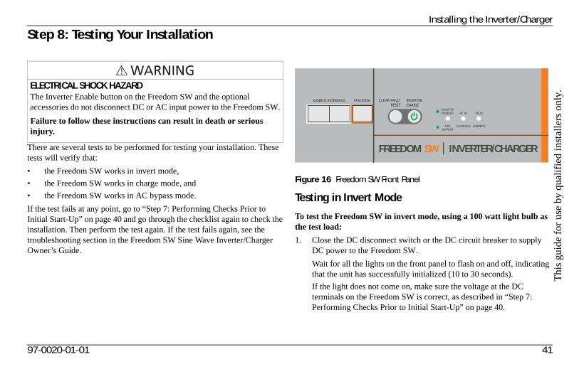
Thi
s gu
ide
for
use
by q
uali
fied
inst
alle
rs o
nly.
Installing the Inverter/Charger
Step 8: Testing Your Installation
There are several tests to be performed for testing your installation. These tests will verify that:
• the Freedom SW works in invert mode,
• the Freedom SW works in charge mode, and
• the Freedom SW works in AC bypass mode.
If the test fails at any point, go to “Step 7: Performing Checks Prior to Initial Start-Up” on page 40 and go through the checklist again to check the installation. Then perform the test again. If the test fails again, see the troubleshooting section in the Freedom SW Sine Wave Inverter/Charger Owner’s Guide.
Testing in Invert Mode
To test the Freedom SW in invert mode, using a 100 watt light bulb as the test load:
1. Close the DC disconnect switch or the DC circuit breaker to supply DC power to the Freedom SW.
Wait for all the lights on the front panel to flash on and off, indicating that the unit has successfully initialized (10 to 30 seconds).
If the light does not come on, make sure the voltage at the DC terminals on the Freedom SW is correct, as described in “Step 7: Performing Checks Prior to Initial Start-Up” on page 40.
ELECTRICAL SHOCK HAZARDThe Inverter Enable button on the Freedom SW and the optional accessories do not disconnect DC or AC input power to the Freedom SW.
Failure to follow these instructions can result in death or serious injury.
Figure 16 Freedom SW Front Panel
XANBUS INTERFACE STACKING
FREEDOM SW INVERTER/CHARGER
CLEAR FAULTRESET
INVERTERENABLE
INVERTERENABLED AC IN FAULT
GENSUPPORT
CHARGING WARNING
97-0020-01-01 41
Installing the Inverter/Charger
2. After initialization, observe that none of the lights on the front panel
should remain illuminated.
3. Press the Inverter Enable button. Verify that:
• The Inverter Enable button light illuminates,
• The Invert On light illuminates.
4. Connect the Freedom SW to the test load by closing the AC breaker that controls the circuit that the test load is connected to.
If the light bulb illuminates, the Invert mode is working.
5. Press the Inverter Enable button to disable the inverter.
The Invert On light and Inverter Enable button light are off.
Testing in Charge Mode and AC Bypass Mode
1. Close the AC supply breaker to supply AC power to the unit.
To verify that the Freedom SW starts charging:
2. After a few seconds, verify that the AC/Charge light on the front panel is turned on (indicating that the batteries are being charged).
To verify that Freedom SW correctly switches to Bypass mode:
3. Disable the AC source and turn off the inverter by pressing the Inverter Enable button.
4. Connect the test load to the AC output connection of the unit.
5. Enable the AC source and the test load should turn on after ten seconds.
Installation Complete
Your installation is now complete. The inverter/charger is ready for use.
The preceding tests use a light test load (a light bulb) as a test case. If you encounter problems when using a load over 1000 watts (for example, a hair dryer or microwave), see the troubleshooting information in the Freedom SW Sine Wave Inverter/Charger Owner’s Guide.
42 Freedom SW Installation Guide
Thi
s gu
ide
for
use
by q
uali
fied
inst
alle
rs o
nly.
Stacking FeaturesThe Freedom SW inverter/chargers provide supports two stacking configurations. This gives the system engineer and/or installer more options to work with when tailoring a system to meet load demands. Multiple inverter/chargers of different power levels can be installed in a system as stand alone, parallel stacked, or series stacked.
In parallel stacking mode, only two Freedom SW inverter/chargers of the same model can be parallel-stacked. For example, two Freedom SW 2012s can be stacked in parallel as both units each have a 12-volt rating and a power rating of up to 2000 watts. For now, a Freedom SW 2012 which is 12-volt rated cannot be parallel-stacked with a Freedom SW 2024 which is 24-volt rated. See parallel stacking section.
In series stacking mode, you may stack two different Freedom SW inverter/chargers of different power ratings but same voltage ratings. For example, a Freedom SW 2012 can be series-stacked with a Freedom SW 3012. However, a Freedom SW 2012 which is 12-volt rated cannot be series-stacked with a Freedom SW 2024 which is 24-volt rated. See series stacking section.
DAMAGE TO INVERTER/CHARGERWhen stacking two Dual Input Line/Dual Output Line (DI-DO) models such as two Freedom SW 3012 units, do not connect any wires to the AC INPUT L2 terminals on both units at all. The same applies to the AC OUTPUT L2 terminals on both units. Any damage sustained by non-compliance may result in non warrantable damage to the inverter/chargers. The only exception is AC OUTPUT N2. See parallel stacking section.
Failure to follow these instructions can damage the unit and/or damage other equipment.
97-0020-01-01 43
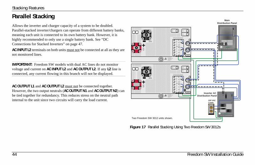
Stacking Features
Parallel StackingAllows the inverter and charger capacity of a system to be doubled. Parallel-stacked inverter/chargers can operate from different battery banks, meaning each unit is connected to its own battery bank. However, it is highly recommended to only use a single battery bank. See “DC Connections for Stacked Inverters” on page 47.
AC INPUT L2 terminals on both units must not be connected at all as they are not monitored lines.
AC OUTPUT L1 and AC OUTPUT L2 must not be connected together. However, the two output neutrals (AC OUTPUT N1 and AC OUTPUT N2) can be tied together for redundancy. This reduces stress on the neutral path internal to the unit since two circuits will carry the load current.
IMPORTANT: Freedom SW models with dual AC lines do not monitor voltage and current on AC INPUT L2 and AC OUTPUT L2. If any L2 line is connected, any current flowing in this branch will not be displayed.
Figure 17 Parallel Stacking Using Two Freedom SW 3012s
L1NEUTRAL
GROUND
AC IN
WARNING: INCORRECT BATTERY
PO
LARITY W
ILL CA
USE
DAM
AGE
TO U
NIT.
BATTERY NEGATIVE
BA
TTERY
POSITIVE
AC GROUNDS(BEHIND COVER)
AC OUT
AC IN
30AAC
INPU
TLIN
E 1
30AA
C IN
PU
TLIN
E 2
30AIN
VER
TERAC
OU
TPUT
Wiring box cover must be in place during use to reduce risk of injury to persons
REM BTS
DC Ground orGrounding ElectrodeTerminal. Seemanual for moreinformation.
NL1
L2
N1
L1
L2
N2
WARNING: INCORRECT BATTERY
PO
LARITY W
ILL CA
US
E DAM
AGE
TO U
NIT.
BATTERY NEGATIVE
BA
TTERY
POSITIVE
AC GROUNDS(BEHIND COVER)
AC OUT
30AAC
INPU
TLIN
E 1
30AA
C IN
PU
TLIN
E 2
30AIN
VERTE
RAC
OU
TPUT
Wiring box cover must be in place during use to reduce risk of injury to persons
REM BTS
DC Ground orGrounding ElectrodeTerminal. Seemanual for moreinformation.
120 VACLoads
Inverter AC Distribution Panel
NEUTRAL
GROUND
30A30A
INPUTOUTPUT
AC INN
L1
L2
N1
L1
L2
N2
INPUTOUTPUT
MainDistribution Panel
Two Freedom SW 3012 units shown.
44 Freedom SW Installation Guide
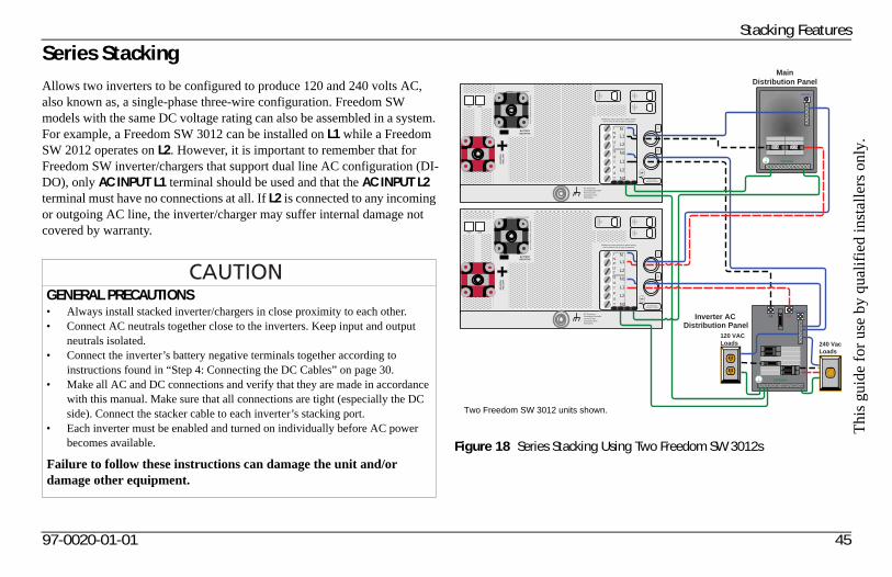
Thi
s gu
ide
for
use
by q
uali
fied
inst
alle
rs o
nly.
Stacking Features
Series StackingAllows two inverters to be configured to produce 120 and 240 volts AC, also known as, a single-phase three-wire configuration. Freedom SW models with the same DC voltage rating can also be assembled in a system. For example, a Freedom SW 3012 can be installed on L1 while a Freedom SW 2012 operates on L2. However, it is important to remember that for Freedom SW inverter/chargers that support dual line AC configuration (DI-DO), only AC INPUT L1 terminal should be used and that the AC INPUT L2 terminal must have no connections at all. If L2 is connected to any incoming or outgoing AC line, the inverter/charger may suffer internal damage not covered by warranty.
GENERAL PRECAUTIONS• Always install stacked inverter/chargers in close proximity to each other. • Connect AC neutrals together close to the inverters. Keep input and output
neutrals isolated.• Connect the inverter’s battery negative terminals together according to
instructions found in “Step 4: Connecting the DC Cables” on page 30.• Make all AC and DC connections and verify that they are made in accordance
with this manual. Make sure that all connections are tight (especially the DC side). Connect the stacker cable to each inverter’s stacking port.
• Each inverter must be enabled and turned on individually before AC power becomes available.
Failure to follow these instructions can damage the unit and/or damage other equipment.
Figure 18 Series Stacking Using Two Freedom SW 3012s
NEUTRAL
GROUND
MainDistribution Panel
30A
L1 L2NEUTRAL
GROUND
120 VACLoads 240 Vac
Loads
Inverter AC Distribution Panel
AC IN
WARNING: INCORRECT BATTERY
PO
LARITY W
ILL CA
USE
DAM
AGE
TO U
NIT.
BATTERY NEGATIVE
BA
TTERY
PO
SITIVE
AC GROUNDS(BEHIND COVER)
AC OUT
30AAC
INPU
TLIN
E 1
30AA
C IN
PU
TLIN
E 2
30AIN
VER
TERAC
OU
TPUT
Wiring box cover must be in place during use to reduce risk of injury to persons
REM BTS
DC Ground orGrounding ElectrodeTerminal. Seemanual for moreinformation.
WARNING: INCORRECT BATTERY
PO
LARITY W
ILL CA
US
E DAM
AGE
TO U
NIT.
BATTERY NEGATIVE
BA
TTERY
POSITIVE
AC GROUNDS(BEHIND COVER)
AC OUT
30AAC
INPU
TLIN
E 1
30AA
C IN
PU
TLIN
E 2
30AIN
VERTE
RAC
OU
TPUT
Wiring box cover must be in place during use to reduce risk of injury to persons
REM BTS
DC Ground orGrounding ElectrodeTerminal. Seemanual for moreinformation.
AC INN
L1
L2
N1
L1
L2
N2
INPUTOUTPUT
AC INN
L1
L2
N1
L1
L2
N2
INPUTOUTPUT
30A
Two Freedom SW 3012 units shown.
97-0020-01-01 45
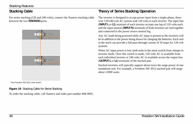
Stacking Features
Stacking Cable
For series stacking (120 and 240 volts), connect the Xantrex stacking cable between the two STACKING ports.
To order the stacking cable, call Xantrex and order part number 808-9005.
Theory of Series Stacking Operation
The inverter is designed to accept power input from a single-phase, three-wire 120/240-volt AC system with 120 volts to each inverter. The input line (INPUT L or L1) terminal of each inverter accepts one leg of 120 volts each and the input neutral (INPUT N) terminals of both inverters are tied together and connected to the power source neutral leg.
Any AC loads being powered while AC input is present to the inverters will be in addition to the power being drawn for charging the batteries. Each unit in the stack can provide a full pass-through current of 50 amps for 120-volt systems.
When AC input power is lost, both units in the stack switch from charger to inverter mode. Once this switch is made, 120 volts AC is available from each individual inverter or 240 volts AC is available across the output line (OUTPUT L or L1) terminals of the stacked pair.
Stacked inverters will typically support about twice the surge power of one standalone unit. For example, a Freedom SW 3012 stacked pair will surge about 12000 watts.
Figure 19 Stacking Cable for Series Stacking
CLEAR FAULTRESET
INVERTERENABLED Inverter
OnAC/
Charge Fault
FREEDOM SW INVERTER/CHARGER
STACKINGXANBUS INTERFACE
CLEAR FAULTRESET
INVERTERENABLED Inverter
OnAC/
Charge Fault
FREEDOM SW INVERTER/CHARGER
STACKINGXANBUS INTERFACE
Two Freedom SW 3012 units shown.
46 Freedom SW Installation Guide
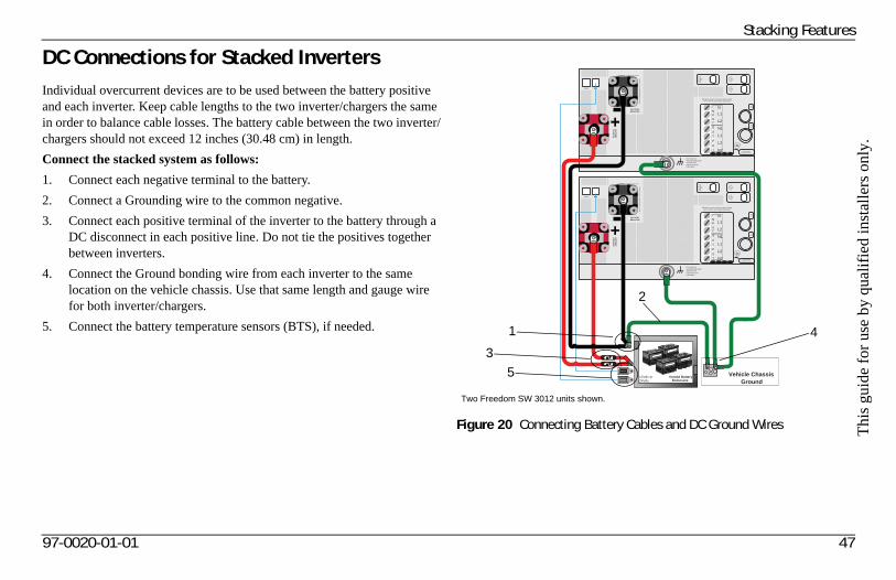
Thi
s gu
ide
for
use
by q
uali
fied
inst
alle
rs o
nly.
Stacking Features
DC Connections for Stacked InvertersIndividual overcurrent devices are to be used between the battery positive and each inverter. Keep cable lengths to the two inverter/chargers the same in order to balance cable losses. The battery cable between the two inverter/chargers should not exceed 12 inches (30.48 cm) in length.
Connect the stacked system as follows:
1. Connect each negative terminal to the battery.
2. Connect a Grounding wire to the common negative.
3. Connect each positive terminal of the inverter to the battery through a DC disconnect in each positive line. Do not tie the positives together between inverters.
4. Connect the Ground bonding wire from each inverter to the same location on the vehicle chassis. Use that same length and gauge wire for both inverter/chargers.
5. Connect the battery temperature sensors (BTS), if needed.
Figure 20 Connecting Battery Cables and DC Ground Wires
Vented Battery Enclosure
12Vdc or24Vdc
Vehicle Chassis Ground
AC IN
WARNING: INCORRECT BATTERY
PO
LARITY W
ILL CA
USE
DAM
AGE
TO U
NIT.
BATTERY NEGATIVE
BA
TTERY
POSITIVE
AC GROUNDS(BEHIND COVER)
AC OUT
30AAC
INPU
TLIN
E 1
30AA
C IN
PU
TLIN
E 2
30AIN
VER
TERAC
OU
TPUT
Wiring box cover must be in place during use to reduce risk of injury to persons
REM BTS
DC Ground orGrounding ElectrodeTerminal. Seemanual for moreinformation.
WARNING: INCORRECT BATTERY
PO
LARITY W
ILL CA
US
E DAM
AGE
TO U
NIT.
BATTERY NEGATIVE
BA
TTERY
POSITIVE
AC GROUNDS(BEHIND COVER)
AC OUT
30AAC
INPU
TLIN
E 1
30AA
C IN
PU
TLIN
E 2
30AIN
VERTE
RAC
OU
TPUT
Wiring box cover must be in place during use to reduce risk of injury to persons
REM BTS
DC Ground orGrounding ElectrodeTerminal. Seemanual for moreinformation.
xantrex
xantrex
AC INN
L1
L2
N1
L1
L2
N2
INPUTOUTPUT
AC INN
L1
L2
N1
L1
L2
N2
INPUTOUTPUT
Two Freedom SW 3012 units shown.
1
2
3
4
5
97-0020-01-01 47
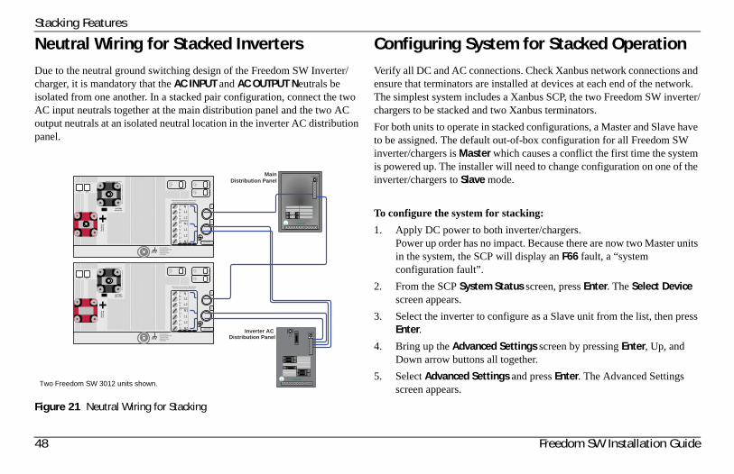
Stacking Features
Neutral Wiring for Stacked InvertersDue to the neutral ground switching design of the Freedom SW Inverter/charger, it is mandatory that the AC INPUT and AC OUTPUT Neutrals be isolated from one another. In a stacked pair configuration, connect the two AC input neutrals together at the main distribution panel and the two AC output neutrals at an isolated neutral location in the inverter AC distribution panel.
Configuring System for Stacked OperationVerify all DC and AC connections. Check Xanbus network connections and ensure that terminators are installed at devices at each end of the network. The simplest system includes a Xanbus SCP, the two Freedom SW inverter/chargers to be stacked and two Xanbus terminators.
For both units to operate in stacked configurations, a Master and Slave have to be assigned. The default out-of-box configuration for all Freedom SW inverter/chargers is Master which causes a conflict the first time the system is powered up. The installer will need to change configuration on one of the inverter/chargers to Slave mode.
To configure the system for stacking:
1. Apply DC power to both inverter/chargers.Power up order has no impact. Because there are now two Master units in the system, the SCP will display an F66 fault, a “system configuration fault”.
2. From the SCP System Status screen, press Enter. The Select Device screen appears.
3. Select the inverter to configure as a Slave unit from the list, then press Enter.
4. Bring up the Advanced Settings screen by pressing Enter, Up, and Down arrow buttons all together.
5. Select Advanced Settings and press Enter. The Advanced Settings screen appears.
Figure 21 Neutral Wiring for Stacking
L1NEUTRAL
GROUND
AC IN
WARNING: INCORRECT BATTERY
PO
LARITY W
ILL CA
USE
DAM
AGE
TO U
NIT.
BATTERY NEGATIVE
BA
TTERY
POSITIVE
AC GROUNDS(BEHIND COVER)
AC OUT
AC IN
30AAC
INPU
TLIN
E 1
30AA
C IN
PU
TLIN
E 2
30AIN
VER
TERAC
OU
TPUT
Wiring box cover must be in place during use to reduce risk of injury to persons
REM BTS
DC Ground orGrounding ElectrodeTerminal. Seemanual for moreinformation.
NL1
L2
N1
L1
L2
N2
WARNING: INCORRECT BATTERY
PO
LARITY W
ILL CA
US
E DAM
AGE
TO U
NIT.
BATTERY NEGATIVE
BA
TTERY
POSITIVE
AC GROUNDS(BEHIND COVER)
AC OUT
30AAC
INPU
TLIN
E 1
30AA
C IN
PU
TLIN
E 2
30AIN
VERTE
RAC
OU
TPUT
Wiring box cover must be in place during use to reduce risk of injury to persons
REM BTS
DC Ground orGrounding ElectrodeTerminal. Seemanual for moreinformation.
Inverter AC Distribution Panel
NEUTRAL
GROUND
30A30A
INPUTOUTPUT
AC INN
L1
L2
N1
L1
L2
N2
INPUTOUTPUT
MainDistribution Panel
Two Freedom SW 3012 units shown.
48 Freedom SW Installation Guide
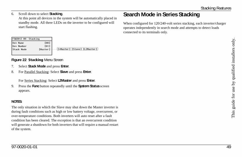
Thi
s gu
ide
for
use
by q
uali
fied
inst
alle
rs o
nly.
Stacking Features6. Scroll down to select Stacking.
At this point all devices in the system will be automatically placed in standby mode. All three LEDs on the inverter to be configured will start flashing.
7. Select Stack Mode and press Enter.
8. For Parallel Stacking: Select Slave and press Enter.
For Series Stacking: Select L2Master and press Enter.
9. Press the Func button repeatedly until the System Status screen appears.
NOTES:
The only situation in which the Slave may shut down the Master inverter is during fault conditions such as high or low battery voltage, overcurrent, or over-temperature conditions. Both inverters will auto reset after a fault condition has been cleared. The exception is that an overcurrent condition will generate a shutdown for both inverters that will require a manual restart of the system.
Search Mode in Series StackingWhen configured for 120/240-volt series stacking, each inverter/charger operates independently in search mode and attempts to detect loads connected to its terminals only.
Figure 22 Stacking Menu Screen
FSW3012 00: Stacking
Dev NameDev NumberStack Mode
[00][01]
[Master] [*Master] [Slave] [L2Master]
97-0020-01-01 49
Stacking Features
50 Freedom SW Installation Guide
Search Mode Operation in Parallel StackingWhen two inverter/chargers are stacked for parallel operation, search mode behavior on the Slave unit is modified and is dependent on how much total load is on the system.
Disabling Search Mode on the Master Unit
In parallel stacking, search mode on the Master unit will not function properly. When the Master sends out a load search pulse, a small current also flows into the output of the Slave unit since the two outputs are in parallel. This Master unit falsely detects a load causing erratic search mode operation. For this reason, it is highly recommended to disable search mode on the Master unit in a parallel stacking system.
Setting Search Mode on the Slave Unit
The Slave unit will behave in one of two ways depending on whether its search mode is enabled or disabled.
Search mode enabled This is the recommended mode for parallel stacking and it helps minimize battery draw. The Slave unit continuously monitors the output of the Master unit. If the Master unit has more than 60% of the rated load (e.g., 1800 watts on Freedom SW 3012), the Slave unit will assist the Master and the two will share the load equally. Should the load on the Master drop below 20% of rated load (600 watts for Freedom SW 3012), the Slave unit disengages and returns to a waiting state.
Search mode disabled The Slave unit operates continuously along with the Master unit and shares the load.
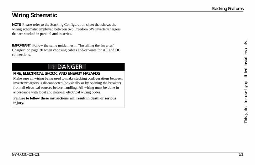
Thi
s gu
ide
for
use
by q
uali
fied
inst
alle
rs o
nly.
Stacking Features
Wiring SchematicNOTE: Please refer to the Stacking Configuration sheet that shows the wiring schematic employed between two Freedom SW inverter/chargers that are stacked in parallel and in series.
IMPORTANT: Follow the same guidelines in “Installing the Inverter/Charger” on page 20 when choosing cables and/or wires for AC and DC connections.
FIRE, ELECTRICAL SHOCK, AND ENERGY HAZARDSMake sure all wiring being used to make stacking configurations between inverter/chargers is disconnected (physically or by opening the breaker) from all electrical sources before handling. All wiring must be done in accordance with local and national electrical wiring codes.
Failure to follow these instructions will result in death or serious injury.
97-0020-01-01 51
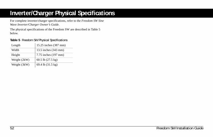
Inverter/Charger Physical SpecificationsFor complete inverter/charger specifications, refer to the Freedom SW Sine Wave Inverter/Charger Owner’s Guide.
The physical specifications of the Freedom SW are described in Table 5 below.
Table 5 Freedom SW Physical Specifications
Length 15.25 inches (387 mm)
Width 13.5 inches (343 mm)
Height 7.75 inches (197 mm)
Weight (2kW) 60.5 lb (27.5 kg)
Weight (3kW) 69.4 lb (31.5 kg)
52 Freedom SW Installation Guide
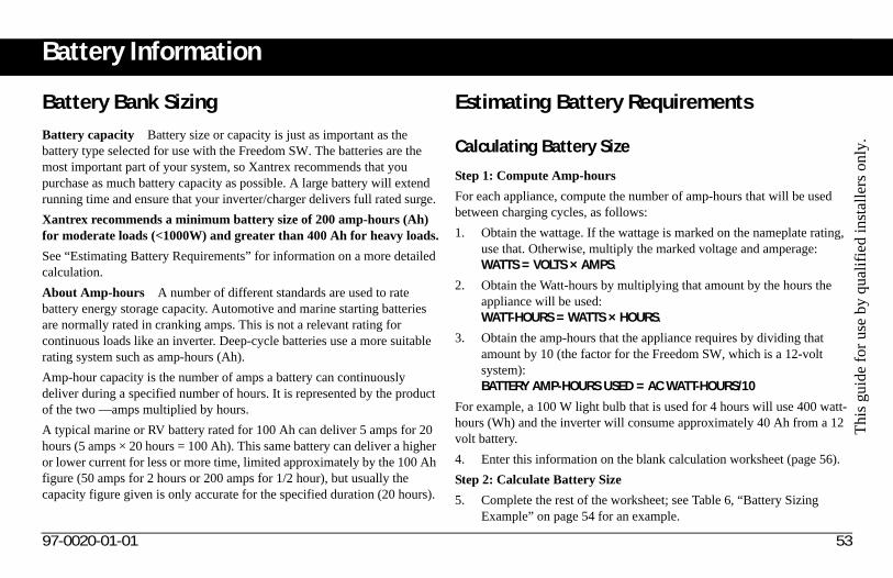
Thi
s gu
ide
for
use
by q
uali
fied
inst
alle
rs o
nly.
Battery Information
Battery Bank SizingBattery capacity Battery size or capacity is just as important as the battery type selected for use with the Freedom SW. The batteries are the most important part of your system, so Xantrex recommends that you purchase as much battery capacity as possible. A large battery will extend running time and ensure that your inverter/charger delivers full rated surge.
Xantrex recommends a minimum battery size of 200 amp-hours (Ah) for moderate loads (<1000W) and greater than 400 Ah for heavy loads.
See “Estimating Battery Requirements” for information on a more detailed calculation.
About Amp-hours A number of different standards are used to rate battery energy storage capacity. Automotive and marine starting batteries are normally rated in cranking amps. This is not a relevant rating for continuous loads like an inverter. Deep-cycle batteries use a more suitable rating system such as amp-hours (Ah).
Amp-hour capacity is the number of amps a battery can continuously deliver during a specified number of hours. It is represented by the product of the two —amps multiplied by hours.
A typical marine or RV battery rated for 100 Ah can deliver 5 amps for 20 hours (5 amps × 20 hours = 100 Ah). This same battery can deliver a higher or lower current for less or more time, limited approximately by the 100 Ah figure (50 amps for 2 hours or 200 amps for 1/2 hour), but usually the capacity figure given is only accurate for the specified duration (20 hours).
Estimating Battery Requirements
Calculating Battery Size
Step 1: Compute Amp-hours
For each appliance, compute the number of amp-hours that will be used between charging cycles, as follows:
1. Obtain the wattage. If the wattage is marked on the nameplate rating, use that. Otherwise, multiply the marked voltage and amperage: WATTS = VOLTS × AMPS.
2. Obtain the Watt-hours by multiplying that amount by the hours the appliance will be used:WATT-HOURS = WATTS × HOURS.
3. Obtain the amp-hours that the appliance requires by dividing that amount by 10 (the factor for the Freedom SW, which is a 12-volt system):BATTERY AMP-HOURS USED = AC WATT-HOURS/10
For example, a 100 W light bulb that is used for 4 hours will use 400 watt-hours (Wh) and the inverter will consume approximately 40 Ah from a 12 volt battery.
4. Enter this information on the blank calculation worksheet (page 56).
Step 2: Calculate Battery Size
5. Complete the rest of the worksheet; see Table 6, “Battery Sizing Example” on page 54 for an example.
97-0020-01-01 53
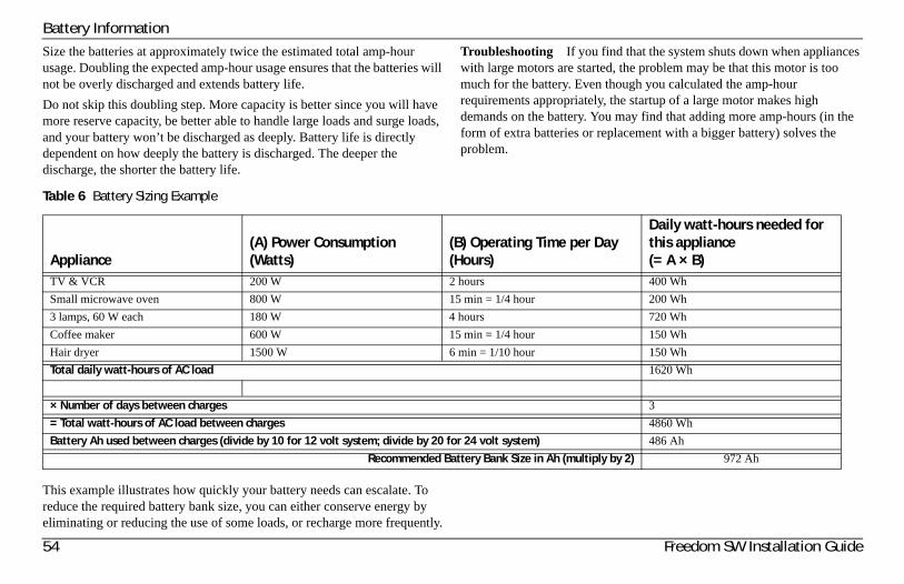
Battery Information
Size the batteries at approximately twice the estimated total amp-hour usage. Doubling the expected amp-hour usage ensures that the batteries will not be overly discharged and extends battery life.
Do not skip this doubling step. More capacity is better since you will have more reserve capacity, be better able to handle large loads and surge loads, and your battery won’t be discharged as deeply. Battery life is directly dependent on how deeply the battery is discharged. The deeper the discharge, the shorter the battery life.
Troubleshooting If you find that the system shuts down when appliances with large motors are started, the problem may be that this motor is too much for the battery. Even though you calculated the amp-hour requirements appropriately, the startup of a large motor makes high demands on the battery. You may find that adding more amp-hours (in the form of extra batteries or replacement with a bigger battery) solves the problem.
Table 6 Battery Sizing Example
This example illustrates how quickly your battery needs can escalate. To reduce the required battery bank size, you can either conserve energy by eliminating or reducing the use of some loads, or recharge more frequently.
Appliance(A) Power Consumption (Watts)
(B) Operating Time per Day (Hours)
Daily watt-hours needed for this appliance(= A × B)
TV & VCR 200 W 2 hours 400 Wh
Small microwave oven 800 W 15 min = 1/4 hour 200 Wh
3 lamps, 60 W each 180 W 4 hours 720 Wh
Coffee maker 600 W 15 min = 1/4 hour 150 Wh
Hair dryer 1500 W 6 min = 1/10 hour 150 Wh
Total daily watt-hours of AC load 1620 Wh
× Number of days between charges 3
= Total watt-hours of AC load between charges 4860 Wh
Battery Ah used between charges (divide by 10 for 12 volt system; divide by 20 for 24 volt system) 486 Ah
Recommended Battery Bank Size in Ah (multiply by 2) 972 Ah
54 Freedom SW Installation Guide
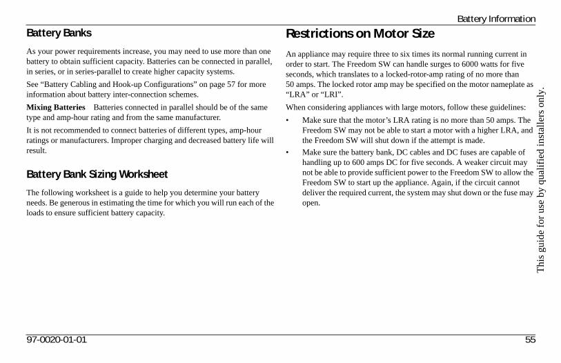
Thi
s gu
ide
for
use
by q
uali
fied
inst
alle
rs o
nly.
Battery Information
Battery Banks
As your power requirements increase, you may need to use more than one battery to obtain sufficient capacity. Batteries can be connected in parallel, in series, or in series-parallel to create higher capacity systems.
See “Battery Cabling and Hook-up Configurations” on page 57 for more information about battery inter-connection schemes.
Mixing Batteries Batteries connected in parallel should be of the same type and amp-hour rating and from the same manufacturer.
It is not recommended to connect batteries of different types, amp-hour ratings or manufacturers. Improper charging and decreased battery life will result.
Battery Bank Sizing Worksheet
The following worksheet is a guide to help you determine your battery needs. Be generous in estimating the time for which you will run each of the loads to ensure sufficient battery capacity.
Restrictions on Motor SizeAn appliance may require three to six times its normal running current in order to start. The Freedom SW can handle surges to 6000 watts for five seconds, which translates to a locked-rotor-amp rating of no more than 50 amps. The locked rotor amp may be specified on the motor nameplate as “LRA” or “LRI”.
When considering appliances with large motors, follow these guidelines:
• Make sure that the motor’s LRA rating is no more than 50 amps. The Freedom SW may not be able to start a motor with a higher LRA, and the Freedom SW will shut down if the attempt is made.
• Make sure the battery bank, DC cables and DC fuses are capable of handling up to 600 amps DC for five seconds. A weaker circuit may not be able to provide sufficient power to the Freedom SW to allow the Freedom SW to start up the appliance. Again, if the circuit cannot deliver the required current, the system may shut down or the fuse may open.
97-0020-01-01 55
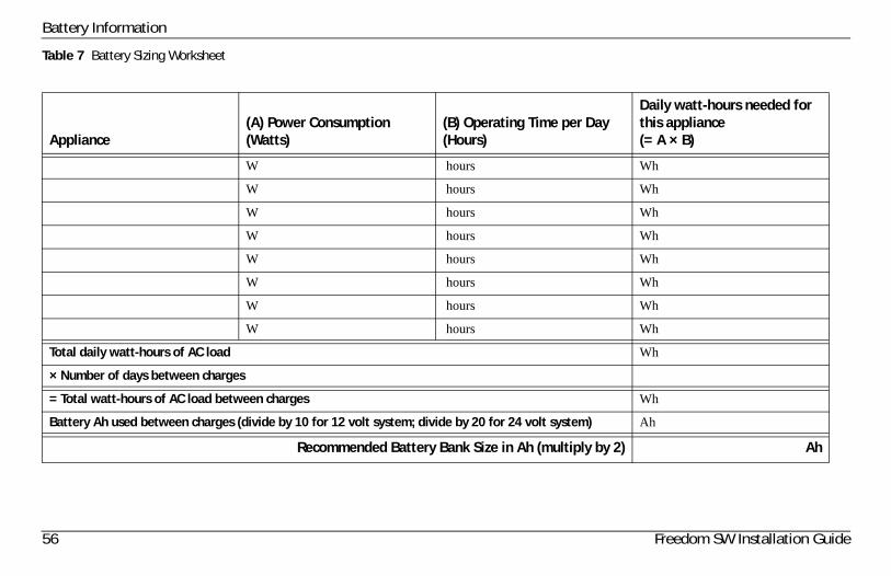
Battery Information
Table 7 Battery Sizing Worksheet
Appliance(A) Power Consumption (Watts)
(B) Operating Time per Day (Hours)
Daily watt-hours needed for this appliance(= A × B)
W hours Wh
W hours Wh
W hours Wh
W hours Wh
W hours Wh
W hours Wh
W hours Wh
W hours Wh
Total daily watt-hours of AC load Wh
× Number of days between charges
= Total watt-hours of AC load between charges Wh
Battery Ah used between charges (divide by 10 for 12 volt system; divide by 20 for 24 volt system) Ah
Recommended Battery Bank Size in Ah (multiply by 2) Ah
56 Freedom SW Installation Guide
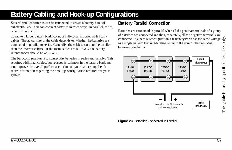
Thi
s gu
ide
for
use
by q
uali
fied
inst
alle
rs o
nly.
Battery Cabling and Hook-up ConfigurationsSeveral smaller batteries can be connected to create a battery bank of substantial size. You can connect batteries in three ways: in parallel, series, or series-parallel.
To make a larger battery bank, connect individual batteries with heavy cables. The actual size of the cable depends on whether the batteries are connected in parallel or series. Generally, the cable should not be smaller than the inverter cables—if the main cables are 4/0 AWG, the battery interconnects should be 4/0 AWG.
The best configuration is to connect the batteries in series and parallel. This requires additional cables, but reduces imbalances in the battery bank and can improve the overall performance. Consult your battery supplier for more information regarding the hook-up configuration required for your system.
Battery Parallel Connection
Batteries are connected in parallel when all the positive terminals of a group of batteries are connected and then, separately, all the negative terminals are connected. In a parallel configuration, the battery bank has the same voltage as a single battery, but an Ah rating equal to the sum of the individual batteries. See below.
Figure 23 Batteries Connected in Parallel
97-0020-01-01 57
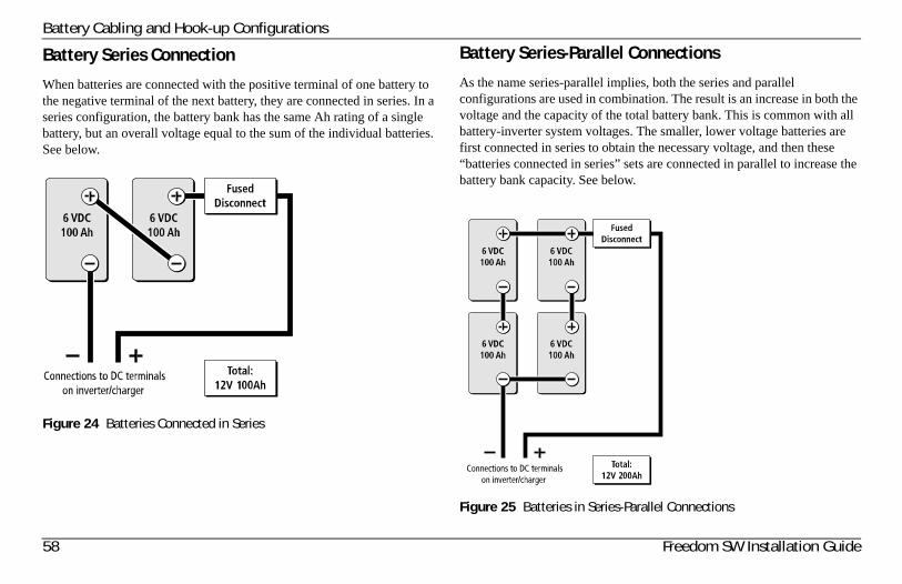
Battery Cabling and Hook-up Configurations
Battery Series Connection
When batteries are connected with the positive terminal of one battery to the negative terminal of the next battery, they are connected in series. In a series configuration, the battery bank has the same Ah rating of a single battery, but an overall voltage equal to the sum of the individual batteries. See below.
Battery Series-Parallel Connections
As the name series-parallel implies, both the series and parallel configurations are used in combination. The result is an increase in both the voltage and the capacity of the total battery bank. This is common with all battery-inverter system voltages. The smaller, lower voltage batteries are first connected in series to obtain the necessary voltage, and then these “batteries connected in series” sets are connected in parallel to increase the battery bank capacity. See below.
Figure 24 Batteries Connected in Series
Figure 25 Batteries in Series-Parallel Connections
58 Freedom SW Installation Guide
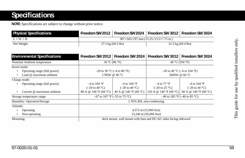
Thi
s gu
ide
for
use
by q
uali
fied
inst
alle
rs o
nly.
SpecificationsNOTE: Specifications are subject to change without prior notice.
Physical Specifications Freedom SW 2012 Freedom SW 2024 Freedom SW 3012 Freedom SW 3024L × W × H 387×343×197 mm (15.25×13.5×7.75 in.)
Net Weight 27.5 kg (60.5 lbs) 31.5 kg (69.4 lbs)
Environmental Specifications Freedom SW 2012 Freedom SW 2024 Freedom SW 3012 Freedom SW 3024Nominal Ambient temperature 30 °C (86 °F) 40 °C (104 °F)
Invert mode:• Operating range (full power)• Load @ maximum ambient
–20 to 30 °C (–4 to 86 °F)1700W @ 60 °C
–20 to 40 °C (–4 to 104 °F)2600W @ 60 °C
Charge mode: • Operating range (full power)
• Current @ maximum ambient
–4 to 104 °F(–20 to 40 °C)
80 A @ 140 °F (60 °C)
–4 to 104 °F(–20 to 40 °C)
40 A @ 140 °F (60 °C)
–4 to 77 °F(–20 to 25 °C)
120 A @ 140 °F (60 °C)
–4 to 104 °F(–20 to 40 °C)
60 A @ 140 °F (60 °C)
Storage temperature range –67 to 167 °F (–55 to 75 °C) –40 to 185 °F (–40 to 85 °C)
Humidity: Operation/Storage 95% RH, non-condensing
Altitude: • Operating• Non-operating
4,572 m (15,000 feet)15,240 m (50,000 feet)
Mounting deck mount, wall mount with fans and DC/AC sides facing sideward
97-0020-01-01 59
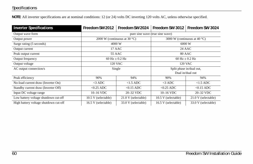
Specifications
NOTE: All inverter specifications are at nominal conditions: 12 (or 24) volts DC inverting 120 volts AC, unless otherwise specified.
Inverter Specifications Freedom SW 2012 Freedom SW 2024 Freedom SW 3012 Freedom SW 3024Output wave form pure sine wave (true sine wave)
Output power 2000 W (continuous at 30 °C) 3000 W (continuous at 40 °C)
Surge rating (5 seconds) 4000 W 6000 W
Output current 17 AAC 24 AAC
Peak output current 55 AAC 80 AAC
Output frequency 60 Hz ± 0.2 Hz 60 Hz ± 0.2 Hz
Output voltage 120 VAC 120 VAC
AC output connection/s Single Split phase in/dual out,Dual in/dual out
Peak efficiency 90% 94% 90% 94%
No-load current draw (Inverter On) <3 ADC <1.5 ADC <3 ADC <1.5 ADC
Standby current draw (Inverter Off) <0.25 ADC <0.15 ADC <0.25 ADC <0.15 ADC
Input DC voltage range 10–16 VDC 20–32 VDC 10–16 VDC 20–32 VDC
Low battery voltage shutdown cut-off 10.5 V (selectable) 21.0 V (selectable) 10.5 V (selectable) 21.0 V (selectable)
High battery voltage shutdown cut-off 16.5 V (selectable) 33.0 V (selectable) 16.5 V (selectable) 33.0 V (selectable)
60 Freedom SW Installation Guide
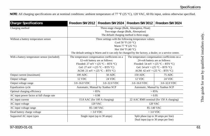
Thi
s gu
ide
for
use
by q
uali
fied
inst
alle
rs o
nly.
97-0020-01-01 61
Specifications
NOTE: All charging specifications are at nominal conditions: ambient temperature of 77 °F (25 °C), 120 VAC, 60 Hz input, unless otherwise specified.
Charger Specifications Freedom SW 2012 Freedom SW 2024 Freedom SW 3012 Freedom SW 3024Charging method Three-stage charge (Bulk, Absorption, Float)
Two-stage charge (Bulk, Absorption)The default charging method is three-stage.
Without a battery temperature sensor Three settings with the following temperature values:Cool 50 °F (10 °C)Warm 77 °F (25 °C)Hot 104 °F (40 °C)
The default setting is Warm and it can only be changed by the factory, a dealer, or a service centre.
With a battery temperature sensor (included) The temperature compensation coefficients on a 12-volt battery are as follows:
Flooded: 27 mV × (25 °C – BTS °C)Gel: 27 mV × (25 °C – BTS °C)
AGM: 21 mV × (25 °C – BTS °C)
The temperature compensation coefficients on a24-volt battery are as follows:
Flooded: 54 mV × (25 °C – BTS °C)Gel: 54 mV × (25 °C – BTS °C)
AGM: 42 mV × (25 °C – BTS °C)
Output current (maximum) 100 ADC 50 ADC 150 ADC 75 ADC
Output voltage 12 VDC 24 VDC 12 VDC 24 VDC
Output voltage range 3.0–16.0 VDC 3.0–32.0 VDC 3.0–16.0 VDC 3.0–32.0 VDC
Equalization cycle Automatic, Manual by Xanbus SCP Automatic, Manual by Xanbus SCP
Optimal charging efficiency > 85% > 85%
AC input power factor at full charge rate > 0.98 > 0.95
AC input current 15.8 AAC (for 100 A charging) 22 AAC RMS nominal (for 150 A charging)
AC input voltage 120 VAC 120 VAC
AC input voltage range 85–140 VAC 85–140 VAC
Dead battery charge voltage > 3.0 VDC > 3.0 VDC
Supported AC input types Single input (up to 30 amps) Split phase (up to 30 amps per line)Dual input (up to 30 amps per line)
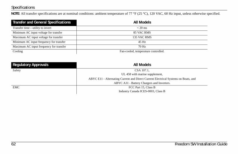
Specifications
62 Freedom SW Installation Guide
NOTE: All transfer specifications are at nominal conditions: ambient temperature of 77 °F (25 °C), 120 VAC, 60 Hz input, unless otherwise specified.
Transfer and General Specifications All ModelsTransfer time—utility to invert < 20 ms
Minimum AC input voltage for transfer 85 VAC RMS
Maximum AC input voltage for transfer 135 VAC RMS
Minimum AC input frequency for transfer 45 Hz
Maximum AC input frequency for transfer 70 Hz
Cooling Fan-cooled, temperature controlled.
Regulatory Approvals All ModelsSafety CSA 107.1,
UL 458 with marine supplement,
ABYC E11 - Alternating Current and Direct Current Electrical Systems on Boats, andABYC A31 - Battery Chargers and Inverters.
EMC FCC Part 15, Class BIndustry Canada ICES-0003, Class B


Xantrex Technology Inc.
1 800 670 0707 Tel toll free1 408 987 6030 Tel direct1 800 994 7828 Fax toll freewww.xantrex.com
97-0020-01-01