Embed Size (px)
Citation preview
TM
TM
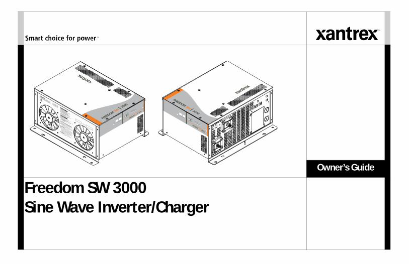
Freedom SW 3000Sine Wave Inverter/Charger
Owner’s Guide
FREEDOM SW 3000
Inverter
Reset
Enable
Inverter
AC/
On
Charge Fault
Xanbus Interfa
ce
FREEDOM SW 3000
Inverter
Reset Enable
Inverter AC/
On Charge Fault
Xanbus Interface
Date of Manufacture
Serial Number
CAUTION: To reduce the risk of fire, do not
cover or obstruct ventilation openings. Do not mount
in a zero-clearance compartment. Overheating may
result. Do not expose to rain or spray.
INSTALLATION REQUIREMENTS:
Mount this inverter/charger only in the orientations
specified in the installation guide provided.
WARNING: Shock hazard. Do not open. No
user serviceable parts. Energized from both AC and
DC sources. Disconnect all sources before servicing.
Use only ground-fault circuit interrupters (GFCI)
specified in the installation guide supplied. Other
types may fail to operate properly when connected to
this equipment. Refer to manual. Charge only
lead-acid batteries. Other battery types may burst
causing personal injury and damage.
Nominal DC Operating Voltage: 12 Vdc
Nominal AC Output Voltage: 120 Vac , 1Ø
Nominal AC Output Frequency: 60 Hz
Max. Continuous AC Output Current: 25 A
Max. Operating DC Input Current: 320 A
Max. Continuous AC Output at Nominal DC
Input: 3000 VA at 25°C
Max. Output Surge Power (5 s duration): 6000 VA
Max. DC Input Voltage: 16 Vdc
Max. Ambient Temperature: 50°C
Inverter Mode:
Nominal AC Input Voltage: 120 Vac , 60 Hz, 1Ø
Power Factor: > 0.95
Charging DC Output Voltage Range: 5.0 - 16.0 Vdc
Max. Continuous Battery Charger DC Current at
Nominal AC Input: 150 A
Max. AC Input Current: 30 A per line Split Phase,
30 A per line Dual
Charger Mode:
3000W SINEWAVE INVERTER/CHARGER
FSW3000815-3000
ModelNumberFGANumber
FREEDOM SW 3000
Designed in Canada
Assembled in China
DANGER: To reduce the risk of explosion, do not
install in an area in which ignition-protected
euipment is required.
UL 458CSA 107.1-01
3033614
FREEDOM SW 3000
FREEDOM SW 3000

975-0545-01-01 i
About XantrexXantrex Technology Inc. (www.xantrex.com), a subsidiary of Schneider Electric, is a world leader in the development, manufacturing and marketing of advanced power electronic products and systems for the renewable and mobile power markets. The company's products convert and control raw electrical power from any central, distributed, renewable, or backup power source into high-quality power required by electronic equipment and the electricity grid. Xantrex is headquartered in Vancouver, Canada, with facilities in the United States, Germany, Spain, and a joint venture in China.
TrademarksXantrex and Smart Choice for Power are trademarks of Schneider Electric International Services sprl, registered in the U.S. and other countries. Other trademarks, registered trademarks, and product names are the property of their respective owners and are used herein for identification purposes only.
Notice of CopyrightFreedom SW 3000 Sine Wave Inverter/Charger Owner’s Guide © January 2010 Xantrex Technology Inc. All rights reserved. No part of this document may be reproduced in any form or disclosed to third parties without the express written consent of: Xantrex Technology Inc., 161-G South Vasco Road, Livermore, California, USA 94551. Xantrex Technology Inc. reserves the right to revise this document and to periodically make changes to the content hereof without obligation or organization of such revisions or changes unless required to do so by prior arrangement.
Exclusion for DocumentationUNLESS SPECIFICALLY AGREED TO IN WRITING, XANTREX TECHNOLOGY INC. (“XANTREX”)(A) MAKES NO WARRANTY AS TO THE ACCURACY, SUFFICIENCY OR SUITABILITY OF ANY TECHNICAL OR OTHER INFORMATION PROVIDED IN ITS MANUALS OR OTHER DOCUMENTATION;(B) ASSUMES NO RESPONSIBILITY OR LIABILITY FOR LOSSES, DAMAGES, COSTS OR EXPENSES, WHETHER SPECIAL, DIRECT, INDIRECT, CONSEQUENTIAL OR INCIDENTAL, WHICH MIGHT ARISE OUT OF THE USE OF SUCH INFORMATION. THE USE OF ANY SUCH INFORMATION WILL BE ENTIRELY AT THE USER’S RISK; AND(C) REMINDS YOU THAT IF THIS MANUAL IS IN ANY LANGUAGE OTHER THAN ENGLISH, ALTHOUGH STEPS HAVE BEEN TAKEN TO MAINTAIN THE ACCURACY OF THE TRANSLATION, THE ACCURACY CANNOT BE GUARANTEED. APPROVED XANTREX CONTENT IS CONTAINED WITH THE ENGLISH LANGUAGE VERSION WHICH IS POSTED AT WWW.XANTREX.COM.
Date and RevisionJanuary 2010 Rev A
Document Part Number975-0545-01-01
Product Number815-3000
Contact InformationTelephone: 1 800 670 0707 (toll free North America)
1 408 987 6030 (direct)Fax: 1 800 994 7828 (toll free North America)Email: [email protected]: www.xantrex.com
ii Freedom SW 3000 Owner’s Guide
About This Guide
PurposeThe purpose of this Owner’s Guide is to provide explanations and procedures for operating, troubleshooting, and maintaining the Freedom SW 3000 Inverter/Charger.
ScopeThe Guide provides safety and operating guidelines as well as information on configuring the inverter/charger. It also provides information about troubleshooting the unit. It does not provide details about particular brands of batteries. You need to consult individual battery manufacturers for this information.
AudienceThe Guide is intended for users and operators of the Freedom SW 3000 Inverter/Charger.
Conventions UsedThe following conventions are used in this guide.
STATEMENT OF HAZARDContains statements of avoidance or strict compliance.Failure to follow these instructions will result in death or serious injury.
STATEMENT OF HAZARDContains statements of avoidance or strict compliance.
Failure to follow these instructions can result in death or serious injury.
STATEMENT OF HAZARDContains statements of avoidance or strict compliance.
Failure to follow these instructions can result in minor or moderate injury.
STATEMENT OF HAZARDContains statements of avoidance or strict compliance.
Failure to follow these instructions can damage the unit and/or damage other equipment.
IMPORTANT: These notes describe things which are important for you to know, however, they are not as serious as a caution or warning.
975-0545-01-01 iii
Related InformationYou can find more information about Xantrex Technology Inc. as well as its products and services at www.xantrex.com.
NOTE: The Installation Guide (Document Part Number: 975-0546-01-01) is primarily intended for qualified installers who need to install and configure the Freedom SW 3000 Inverter/Charger. The installer should have knowledge and experience in installing electrical equipment, knowledge of the applicable installation codes, and awareness of the hazards involved in performing electrical work and how to reduce those hazards. A qualified technician or electrician has this knowledge and experience.
iv Freedom SW 3000 Owner’s Guide
Important Safety Instructions
IMPORTANT: READ AND SAVE THIS OWNER’S GUIDE FOR FUTURE REFERENCE.
This chapter contains important safety and installation instructions for the Freedom SW 3000 Inverter/Charger (Freedom SW 3000). Each time, before using the Freedom SW 3000, READ ALL instructions and cautionary markings on or provided with the inverter/charger, the batteries, and all appropriate sections of this guide.NOTE: The Freedom SW 3000 contains no user-serviceable parts. See “Warranty and Return Information” on page 65 for guidance.
NOTE: Turning off the inverter/charger using the on/off switch on the front panel will not reduce an electrical shock hazard.
ELECTRICAL SHOCK HAZARD• Do not expose the Freedom SW 3000 to rain, snow, spray, or bilge
water. This inverter/charger is designed for indoor use only.• Do not operate the inverter/charger if it has received a sharp blow,
been dropped, has cracks or openings in the enclosure including if the fuse cover has been lost, damaged, or will not close, or otherwise damaged in any other way.
• Do not disassemble the inverter/charger. Internal capacitors remain charged after all power is disconnected.
• Disconnect both AC and DC power from the inverter/charger before attempting any maintenance or cleaning or working on any circuits connected to the inverter/charger. See note below.
• Do not operate the inverter/charger with damaged or substandard wiring. Make sure that all wiring is in good condition and is not undersized.
Failure to follow these instructions will result in death or serious injury.
975-0545-01-01 v
NOTES:1. Follow these instructions and those published by the battery
manufacturer and the manufacturer of any equipment you intend to use in the vicinity of the battery. Review cautionary markings on these products and on the engine.
2. This inverter/charger contains components which tend to produce arcs or sparks.
3. Locations include any space containing gasoline-powered machinery, fuel tanks, as well as joints, fittings, or other connections between components of the fuel system.
FIRE AND BURN HAZARD• Do not cover or obstruct the air intake vent openings and/or install in
a zero-clearance compartment.• Do not use transformerless battery chargers in conjunction with the
inverter/charger due to overheating.Failure to follow these instructions will result in death or serious injury.
EXPLOSION HAZARD• Charge only properly rated (such as 12 V) lead-acid (GEL, AGM,
Flooded, or lead-calcium) rechargeable batteries because other battery types may explode and burst.
• Do not work in the vicinity of lead-acid batteries. Batteries generate explosive gases during normal operation. See note #1.
• Do not install and/or operate in compartments containing flammable materials or in locations that require ignition-protected equipment. See notes #2 and #3.
Failure to follow these instructions will result in death or serious injury.
vi Freedom SW 3000 Owner’s Guide
Precautions When Working With Batteries
NOTES:1. Mount and place the Freedom SW 3000 Inverter/Charger unit away
from batteries in a well ventilated compartment.2. Always have someone within range of your voice or close enough to
come to your aid when you work near a lead-acid battery.3. Always have plenty of fresh water and soap nearby in case battery acid
contacts skin, clothing, or eyes.4. If battery acid contacts skin or clothing, wash immediately with soap
and water. If acid enters your eye, immediately flood it with running cold water for at least twenty minutes and get medical attention immediately.
5. Use extra caution to reduce the risk or dropping a metal tool on the battery. It could spark or short circuit the battery or other electrical parts and could cause an explosion.
6. Batteries can produce a short circuit current high enough to weld a ring or metal bracelet or the like to the battery terminal, causing a severe burn.
7. When removing a battery, always remove the negative terminal from the battery first for systems with grounded negative. If it is grounded positive, remove the positive terminal first. Make sure all loads connected to the battery and all accessories are off so you don’t cause an arc.
BURN FROM HIGH SHORT-CIRCUIT CURRENT, FIRE AND EXPLO-SION FROM VENTED GASES HAZARDS• Always wear proper, non-absorbent gloves, complete eye protection,
and clothing protection. Avoid touching your eyes and wiping your forehead while working near batteries. See note #4.
• Remove all personal metal items, like rings, bracelets, and watches when working with batteries. See notes #5 and #6 below.
• Never smoke or allow a spark or flame near the engine or batteries.• Never charge a frozen battery.Failure to follow these instructions can result in death or serious injury.
975-0545-01-01 vii
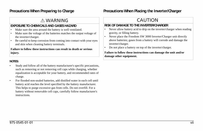
Precautions When Preparing to Charge
NOTES:• Study and follow all of the battery manufacturer's specific precautions,
such as removing or not removing cell caps while charging, whether equalization is acceptable for your battery, and recommended rates of charge.
• For flooded non-sealed batteries, add distilled water in each cell until battery acid reaches the level specified by the battery manufacturer. This helps to purge excessive gas from cells. Do not overfill. For a battery without removable cell caps, carefully follow manufacturer's instructions.
Precautions When Placing the Inverter/Charger
EXPOSURE TO CHEMICALS AND GASES HAZARD• Make sure the area around the battery is well ventilated.• Make sure the voltage of the batteries matches the output voltage of
the inverter/charger.• Be careful to keep corrosion from coming into contact with your eyes
and skin when cleaning battery terminals.Failure to follow these instructions can result in death or serious injury.
RISK OF DAMAGE TO THE INVERTER/CHARGER• Never allow battery acid to drip on the inverter/charger when reading
gravity, or filling battery.• Never place the Freedom SW 3000 Inverter/Charger unit directly
above batteries; gases from a battery will corrode and damage the inverter/charger.
• Do not place a battery on top of the inverter/charger.
Failure to follow these instructions can damage the unit and/or damage other equipment.
viii Freedom SW 3000 Owner’s Guide
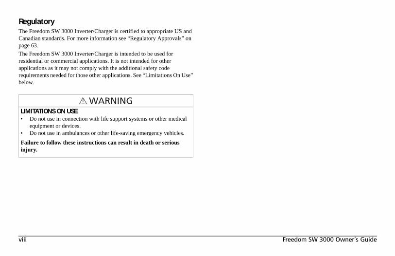
RegulatoryThe Freedom SW 3000 Inverter/Charger is certified to appropriate US and Canadian standards. For more information see “Regulatory Approvals” on page 63.The Freedom SW 3000 Inverter/Charger is intended to be used for residential or commercial applications. It is not intended for other applications as it may not comply with the additional safety code requirements needed for those other applications. See “Limitations On Use” below.
LIMITATIONS ON USE• Do not use in connection with life support systems or other medical
equipment or devices.• Do not use in ambulances or other life-saving emergency vehicles.Failure to follow these instructions can result in death or serious injury.
Important Safety Instructions . . . . . . . . . . . . . . . . . . . . . . . . . . . . . . . . . . . . . . . . . . . . . . . . . . . . . . . . . . . . . . . . . . . . . . . . . . . . . . . . . . . . . iv
Introduction . . . . . . . . . . . . . . . . . . . . . . . . . . . . . . . . . . . . . . . . . . . . . . . . . . . . . . . . . . . . . . . . . . . . . . . . . . . . . . . . . . . . . . . . . . . . . . . . . . . .1Materials List . . . . . . . . . . . . . . . . . . . . . . . . . . . . . . . . . . . . . . . . . . . . . . . . . . . . . . . . . . . . . . . . . . . . . . . . . . . . . . . . . . . . . . . . . . .1About the Freedom SW 3000
Inverter/Charger . . . . . . . . . . . . . . . . . . . . . . . . . . . . . . . . . . . . . . . . . . . . . . . . . . . . . . . . . . . . . . . . . . . . . . . . . . . . . . . . . . . . . . . . . . . . . . . .2Premium Power and Ease of Use . . . . . . . . . . . . . . . . . . . . . . . . . . . . . . . . . . . . . . . . . . . . . . . . . . . . . . . . . . . . . . . . . . . . . . . . . . . .2How the Freedom SW 3000 Inverter/Charger Works . . . . . . . . . . . . . . . . . . . . . . . . . . . . . . . . . . . . . . . . . . . . . . . . . . . . . . . . . . . .3
Inverting . . . . . . . . . . . . . . . . . . . . . . . . . . . . . . . . . . . . . . . . . . . . . . . . . . . . . . . . . . . . . . . . . . . . . . . . . . . . . . . . . . . . . . . . . . .3Charging . . . . . . . . . . . . . . . . . . . . . . . . . . . . . . . . . . . . . . . . . . . . . . . . . . . . . . . . . . . . . . . . . . . . . . . . . . . . . . . . . . . . . . . . . . .3
Xanbus® System . . . . . . . . . . . . . . . . . . . . . . . . . . . . . . . . . . . . . . . . . . . . . . . . . . . . . . . . . . . . . . . . . . . . . . . . . . . . . . . . . . . . . . . .4Comprehensive Electronic Protection . . . . . . . . . . . . . . . . . . . . . . . . . . . . . . . . . . . . . . . . . . . . . . . . . . . . . . . . . . . . . . . . . . . . . . . .5
Freedom SW 3000 Inverter/Charger Features. . . . . . . . . . . . . . . . . . . . . . . . . . . . . . . . . . . . . . . . . . . . . . . . . . . . . . . . . . . . . . . . . . . . . . . . . .6Front and Side Panels . . . . . . . . . . . . . . . . . . . . . . . . . . . . . . . . . . . . . . . . . . . . . . . . . . . . . . . . . . . . . . . . . . . . . . . . . . . . . . . . . . . . .6Front and Side Panels . . . . . . . . . . . . . . . . . . . . . . . . . . . . . . . . . . . . . . . . . . . . . . . . . . . . . . . . . . . . . . . . . . . . . . . . . . . . . . . . . . . . .7AC and DC Side Panels . . . . . . . . . . . . . . . . . . . . . . . . . . . . . . . . . . . . . . . . . . . . . . . . . . . . . . . . . . . . . . . . . . . . . . . . . . . . . . . . . . .9Supplied Accessories . . . . . . . . . . . . . . . . . . . . . . . . . . . . . . . . . . . . . . . . . . . . . . . . . . . . . . . . . . . . . . . . . . . . . . . . . . . . . . . . . . . .10Optional System Accessories and Network Components . . . . . . . . . . . . . . . . . . . . . . . . . . . . . . . . . . . . . . . . . . . . . . . . . . . . . . . .11
Operating The Freedom SW 3000. . . . . . . . . . . . . . . . . . . . . . . . . . . . . . . . . . . . . . . . . . . . . . . . . . . . . . . . . . . . . . . . . . . . . . . . . . . . . . . . . .12Operating the Freedom SW 3000 with the Optional System Control Panel (SCP) . . . . . . . . . . . . . . . . . . . . . . . . . . . . . . . . . . . . .12Using the SCP . . . . . . . . . . . . . . . . . . . . . . . . . . . . . . . . . . . . . . . . . . . . . . . . . . . . . . . . . . . . . . . . . . . . . . . . . . . . . . . . . . . . . . . . .13
Contents
On Start Up . . . . . . . . . . . . . . . . . . . . . . . . . . . . . . . . . . . . . . . . . . . . . . . . . . . . . . . . . . . . . . . . . . . . . . . . . . . . . . . . . . . . . . . . . . .14System Start-up Check . . . . . . . . . . . . . . . . . . . . . . . . . . . . . . . . . . . . . . . . . . . . . . . . . . . . . . . . . . . . . . . . . . . . . . . . . . . . . . . . . . .15Viewing the Firmware Revision Number . . . . . . . . . . . . . . . . . . . . . . . . . . . . . . . . . . . . . . . . . . . . . . . . . . . . . . . . . . . . . . . . . . . .15Operating in Invert Mode . . . . . . . . . . . . . . . . . . . . . . . . . . . . . . . . . . . . . . . . . . . . . . . . . . . . . . . . . . . . . . . . . . . . . . . . . . . . . . . . .16
Operating Limits for Inverter Operation . . . . . . . . . . . . . . . . . . . . . . . . . . . . . . . . . . . . . . . . . . . . . . . . . . . . . . . . . . . . . . . . . .16Operating in Charger Mode . . . . . . . . . . . . . . . . . . . . . . . . . . . . . . . . . . . . . . . . . . . . . . . . . . . . . . . . . . . . . . . . . . . . . . . . . . . . . . .17
Charger Operation with Battery TemperatureSensor (BTS) . . . . . . . . . . . . . . . . . . . . . . . . . . . . . . . . . . . . . . . . . . . . . . . . . . . . . . . . . . . . . . . . . . . . . . . . . . . . . . . . . . . . . . . . . . . . . . . . .17
Operating in Equalization Mode . . . . . . . . . . . . . . . . . . . . . . . . . . . . . . . . . . . . . . . . . . . . . . . . . . . . . . . . . . . . . . . . . . . . . . . . . . .18Equalizing Batteries . . . . . . . . . . . . . . . . . . . . . . . . . . . . . . . . . . . . . . . . . . . . . . . . . . . . . . . . . . . . . . . . . . . . . . . . . . . . . . . . .19Terminating the Equalization Process . . . . . . . . . . . . . . . . . . . . . . . . . . . . . . . . . . . . . . . . . . . . . . . . . . . . . . . . . . . . . . . . . . .19Operating Limits for Charger Operation . . . . . . . . . . . . . . . . . . . . . . . . . . . . . . . . . . . . . . . . . . . . . . . . . . . . . . . . . . . . . . . . .20
Monitoring the Freedom SW 3000 Indicator Lights . . . . . . . . . . . . . . . . . . . . . . . . . . . . . . . . . . . . . . . . . . . . . . . . . . . . . . . . . . . .21Faults and Warnings . . . . . . . . . . . . . . . . . . . . . . . . . . . . . . . . . . . . . . . . . . . . . . . . . . . . . . . . . . . . . . . . . . . . . . . . . . . . . . . . .21Monitoring Status Messages on the SCP . . . . . . . . . . . . . . . . . . . . . . . . . . . . . . . . . . . . . . . . . . . . . . . . . . . . . . . . . . . . . . . . .21
System Modes . . . . . . . . . . . . . . . . . . . . . . . . . . . . . . . . . . . . . . . . . . . . . . . . . . . . . . . . . . . . . . . . . . . . . . . . . . . . . . . . . . . . . . . . .22Operating . . . . . . . . . . . . . . . . . . . . . . . . . . . . . . . . . . . . . . . . . . . . . . . . . . . . . . . . . . . . . . . . . . . . . . . . . . . . . . . . . . . . . . . . .22Safe . . . . . . . . . . . . . . . . . . . . . . . . . . . . . . . . . . . . . . . . . . . . . . . . . . . . . . . . . . . . . . . . . . . . . . . . . . . . . . . . . . . . . . . . . . . . . .23
Configuration. . . . . . . . . . . . . . . . . . . . . . . . . . . . . . . . . . . . . . . . . . . . . . . . . . . . . . . . . . . . . . . . . . . . . . . . . . . . . . . . . . . . . . . . . . . . . . . . . .25System Control Panel . . . . . . . . . . . . . . . . . . . . . . . . . . . . . . . . . . . . . . . . . . . . . . . . . . . . . . . . . . . . . . . . . . . . . . . . . . . . . . . . . . . .25System Menu Map . . . . . . . . . . . . . . . . . . . . . . . . . . . . . . . . . . . . . . . . . . . . . . . . . . . . . . . . . . . . . . . . . . . . . . . . . . . . . . . . . . . . . .26
Viewing the System Screen . . . . . . . . . . . . . . . . . . . . . . . . . . . . . . . . . . . . . . . . . . . . . . . . . . . . . . . . . . . . . . . . . . . . . . . . . . .27Viewing the Select Device Menu . . . . . . . . . . . . . . . . . . . . . . . . . . . . . . . . . . . . . . . . . . . . . . . . . . . . . . . . . . . . . . . . . . . . . . .27Selecting the Freedom SW 3000 from the Select Device Menu . . . . . . . . . . . . . . . . . . . . . . . . . . . . . . . . . . . . . . . . . . . . . . .28Selecting and Adjusting the Configurable Settings . . . . . . . . . . . . . . . . . . . . . . . . . . . . . . . . . . . . . . . . . . . . . . . . . . . . . . . . .30Selecting the Default Settings . . . . . . . . . . . . . . . . . . . . . . . . . . . . . . . . . . . . . . . . . . . . . . . . . . . . . . . . . . . . . . . . . . . . . . . . . .30
Menu Structure . . . . . . . . . . . . . . . . . . . . . . . . . . . . . . . . . . . . . . . . . . . . . . . . . . . . . . . . . . . . . . . . . . . . . . . . . . . . . . . . . . . . . . . . .31Device Menu . . . . . . . . . . . . . . . . . . . . . . . . . . . . . . . . . . . . . . . . . . . . . . . . . . . . . . . . . . . . . . . . . . . . . . . . . . . . . . . . . . . . . . . . . .31
Modes . . . . . . . . . . . . . . . . . . . . . . . . . . . . . . . . . . . . . . . . . . . . . . . . . . . . . . . . . . . . . . . . . . . . . . . . . . . . . . . . . . . . . . . . . . . .31Battery . . . . . . . . . . . . . . . . . . . . . . . . . . . . . . . . . . . . . . . . . . . . . . . . . . . . . . . . . . . . . . . . . . . . . . . . . . . . . . . . . . . . . . . . . . . .32AC Input1 . . . . . . . . . . . . . . . . . . . . . . . . . . . . . . . . . . . . . . . . . . . . . . . . . . . . . . . . . . . . . . . . . . . . . . . . . . . . . . . . . . . . . . . . .32AC Out . . . . . . . . . . . . . . . . . . . . . . . . . . . . . . . . . . . . . . . . . . . . . . . . . . . . . . . . . . . . . . . . . . . . . . . . . . . . . . . . . . . . . . . . . . .32
Menu (Basic) . . . . . . . . . . . . . . . . . . . . . . . . . . . . . . . . . . . . . . . . . . . . . . . . . . . . . . . . . . . . . . . . . . . . . . . . . . . . . . . . . . . . . . . . . .33Inverter . . . . . . . . . . . . . . . . . . . . . . . . . . . . . . . . . . . . . . . . . . . . . . . . . . . . . . . . . . . . . . . . . . . . . . . . . . . . . . . . . . . . . . . . . . .33Charger . . . . . . . . . . . . . . . . . . . . . . . . . . . . . . . . . . . . . . . . . . . . . . . . . . . . . . . . . . . . . . . . . . . . . . . . . . . . . . . . . . . . . . . . . . .33Power Share . . . . . . . . . . . . . . . . . . . . . . . . . . . . . . . . . . . . . . . . . . . . . . . . . . . . . . . . . . . . . . . . . . . . . . . . . . . . . . . . . . . . . . .33Equalize . . . . . . . . . . . . . . . . . . . . . . . . . . . . . . . . . . . . . . . . . . . . . . . . . . . . . . . . . . . . . . . . . . . . . . . . . . . . . . . . . . . . . . . . . .34Batt Type . . . . . . . . . . . . . . . . . . . . . . . . . . . . . . . . . . . . . . . . . . . . . . . . . . . . . . . . . . . . . . . . . . . . . . . . . . . . . . . . . . . . . . . . .37Batt Size . . . . . . . . . . . . . . . . . . . . . . . . . . . . . . . . . . . . . . . . . . . . . . . . . . . . . . . . . . . . . . . . . . . . . . . . . . . . . . . . . . . . . . . . . .37Clear Faults . . . . . . . . . . . . . . . . . . . . . . . . . . . . . . . . . . . . . . . . . . . . . . . . . . . . . . . . . . . . . . . . . . . . . . . . . . . . . . . . . . . . . . . .37
Menu (Advanced) . . . . . . . . . . . . . . . . . . . . . . . . . . . . . . . . . . . . . . . . . . . . . . . . . . . . . . . . . . . . . . . . . . . . . . . . . . . . . . . . . . . . . .38Inverter . . . . . . . . . . . . . . . . . . . . . . . . . . . . . . . . . . . . . . . . . . . . . . . . . . . . . . . . . . . . . . . . . . . . . . . . . . . . . . . . . . . . . . . . . . .38Charger . . . . . . . . . . . . . . . . . . . . . . . . . . . . . . . . . . . . . . . . . . . . . . . . . . . . . . . . . . . . . . . . . . . . . . . . . . . . . . . . . . . . . . . . . . .38Power Share . . . . . . . . . . . . . . . . . . . . . . . . . . . . . . . . . . . . . . . . . . . . . . . . . . . . . . . . . . . . . . . . . . . . . . . . . . . . . . . . . . . . . . .38Configure Inv/Chg (Configure Inverter/Charger) . . . . . . . . . . . . . . . . . . . . . . . . . . . . . . . . . . . . . . . . . . . . . . . . . . . . . . . . . .38Equalize . . . . . . . . . . . . . . . . . . . . . . . . . . . . . . . . . . . . . . . . . . . . . . . . . . . . . . . . . . . . . . . . . . . . . . . . . . . . . . . . . . . . . . . . . .38Clear Faults . . . . . . . . . . . . . . . . . . . . . . . . . . . . . . . . . . . . . . . . . . . . . . . . . . . . . . . . . . . . . . . . . . . . . . . . . . . . . . . . . . . . . . . .38View Device Info . . . . . . . . . . . . . . . . . . . . . . . . . . . . . . . . . . . . . . . . . . . . . . . . . . . . . . . . . . . . . . . . . . . . . . . . . . . . . . . . . . .38Basic Menu . . . . . . . . . . . . . . . . . . . . . . . . . . . . . . . . . . . . . . . . . . . . . . . . . . . . . . . . . . . . . . . . . . . . . . . . . . . . . . . . . . . . . . . .38
Sub-Menus . . . . . . . . . . . . . . . . . . . . . . . . . . . . . . . . . . . . . . . . . . . . . . . . . . . . . . . . . . . . . . . . . . . . . . . . . . . . . . . . . . . . . . . . . . . .39Configure Inv/Chg Menu . . . . . . . . . . . . . . . . . . . . . . . . . . . . . . . . . . . . . . . . . . . . . . . . . . . . . . . . . . . . . . . . . . . . . . . . . . . . .39AC Limits (Configure AC Limits) . . . . . . . . . . . . . . . . . . . . . . . . . . . . . . . . . . . . . . . . . . . . . . . . . . . . . . . . . . . . . . . . . . . . . .41View Device Info (View Device Information) . . . . . . . . . . . . . . . . . . . . . . . . . . . . . . . . . . . . . . . . . . . . . . . . . . . . . . . . . . . . .43
Troubleshooting. . . . . . . . . . . . . . . . . . . . . . . . . . . . . . . . . . . . . . . . . . . . . . . . . . . . . . . . . . . . . . . . . . . . . . . . . . . . . . . . . . . . . . . . . . . . . . . .45Introduction . . . . . . . . . . . . . . . . . . . . . . . . . . . . . . . . . . . . . . . . . . . . . . . . . . . . . . . . . . . . . . . . . . . . . . . . . . . . . . . . . . . . . . . . . . .45
Fault Types . . . . . . . . . . . . . . . . . . . . . . . . . . . . . . . . . . . . . . . . . . . . . . . . . . . . . . . . . . . . . . . . . . . . . . . . . . . . . . . . . . . . . . . .45Warning Types . . . . . . . . . . . . . . . . . . . . . . . . . . . . . . . . . . . . . . . . . . . . . . . . . . . . . . . . . . . . . . . . . . . . . . . . . . . . . . . . . . . . .46
Troubleshooting Reference . . . . . . . . . . . . . . . . . . . . . . . . . . . . . . . . . . . . . . . . . . . . . . . . . . . . . . . . . . . . . . . . . . . . . . . . . . . . . . .47General Troubleshooting Guidelines . . . . . . . . . . . . . . . . . . . . . . . . . . . . . . . . . . . . . . . . . . . . . . . . . . . . . . . . . . . . . . . . . . . .47Warning Messages . . . . . . . . . . . . . . . . . . . . . . . . . . . . . . . . . . . . . . . . . . . . . . . . . . . . . . . . . . . . . . . . . . . . . . . . . . . . . . . . . .49Fault Messages . . . . . . . . . . . . . . . . . . . . . . . . . . . . . . . . . . . . . . . . . . . . . . . . . . . . . . . . . . . . . . . . . . . . . . . . . . . . . . . . . . . . .50Inverter Applications . . . . . . . . . . . . . . . . . . . . . . . . . . . . . . . . . . . . . . . . . . . . . . . . . . . . . . . . . . . . . . . . . . . . . . . . . . . . . . . .54
Battery Charging Reference . . . . . . . . . . . . . . . . . . . . . . . . . . . . . . . . . . . . . . . . . . . . . . . . . . . . . . . . . . . . . . . . . . . . . . . . . . . . . . . . . . . . . .55Battery Types . . . . . . . . . . . . . . . . . . . . . . . . . . . . . . . . . . . . . . . . . . . . . . . . . . . . . . . . . . . . . . . . . . . . . . . . . . . . . . . . . . . . . . . . . .55Charge Algorithm Stages . . . . . . . . . . . . . . . . . . . . . . . . . . . . . . . . . . . . . . . . . . . . . . . . . . . . . . . . . . . . . . . . . . . . . . . . . . . . . . . . .56
Three-Stage charging . . . . . . . . . . . . . . . . . . . . . . . . . . . . . . . . . . . . . . . . . . . . . . . . . . . . . . . . . . . . . . . . . . . . . . . . . . . . . . . .56Two-Stage Charging . . . . . . . . . . . . . . . . . . . . . . . . . . . . . . . . . . . . . . . . . . . . . . . . . . . . . . . . . . . . . . . . . . . . . . . . . . . . . . . . .57
Charge Algorithm Graph . . . . . . . . . . . . . . . . . . . . . . . . . . . . . . . . . . . . . . . . . . . . . . . . . . . . . . . . . . . . . . . . . . . . . . . . . . . . . . . . .58Charge Algorithm Definitions . . . . . . . . . . . . . . . . . . . . . . . . . . . . . . . . . . . . . . . . . . . . . . . . . . . . . . . . . . . . . . . . . . . . . . . . . . . . .58Battery Charger Interruption . . . . . . . . . . . . . . . . . . . . . . . . . . . . . . . . . . . . . . . . . . . . . . . . . . . . . . . . . . . . . . . . . . . . . . . . . . . . . .60
Specifications . . . . . . . . . . . . . . . . . . . . . . . . . . . . . . . . . . . . . . . . . . . . . . . . . . . . . . . . . . . . . . . . . . . . . . . . . . . . . . . . . . . . . . . . . . . . . . . . .61Fan Operation . . . . . . . . . . . . . . . . . . . . . . . . . . . . . . . . . . . . . . . . . . . . . . . . . . . . . . . . . . . . . . . . . . . . . . . . . . . . . . . . . . . . . .63Invert Power Derating vs. Ambient Temperature . . . . . . . . . . . . . . . . . . . . . . . . . . . . . . . . . . . . . . . . . . . . . . . . . . . . . . . . . . .64Charger Mode . . . . . . . . . . . . . . . . . . . . . . . . . . . . . . . . . . . . . . . . . . . . . . . . . . . . . . . . . . . . . . . . . . . . . . . . . . . . . . . . . . . . . .64
Warranty and Return Information . . . . . . . . . . . . . . . . . . . . . . . . . . . . . . . . . . . . . . . . . . . . . . . . . . . . . . . . . . . . . . . . . . . . . . . . . . . . . . . . . 65
975-0545-01-01 1
IntroductionCongratulations on your purchase of the Freedom SW 3000 Inverter/Charger (Freedom SW 3000). The Freedom SW 3000 has been designed to give you premium power, ease of use, and outstanding reliability.Please read this chapter to familiarize yourself with the main performance and protection features of the Freedom SW 3000.
Materials ListThe Freedom SW 3000 ships with the following items:• one Freedom SW 3000 unit,• owner’s and installation guides,• Battery Temperature Sensor (BTS),• Freedom SW remote panel with 25-foot communications cable,• DC terminal covers (one red, one black) with two sets of screws, and• two sets of nuts and washers for the DC terminals.
NOTE: If any of the items are missing, contact Xantrex or any authorized Xantrex dealer for replacement. See “Contact Information” on page i.
IMPORTANT: Keep the carton and packing material in case you need to return the Freedom SW 3000 for servicing.
Figure 1 Materials List
REMBTS
FREEDOMSW3000
In ve rter
Res et Enable
Inv e rte rAC/
On
C ha rgeFault
X anbus I n ter fa ce
FREEDOM SW3000
Remote Panel with communications cable
BTS
DC terminal covers with screws
nuts and washers
Freedom SW 3000
Installation and Owner’s Guides
2 Freedom SW 3000 Owner’s Guide
Introduction
About the Freedom SW 3000Inverter/ChargerThe Freedom SW 3000 is a convenient combination of an inverter, multistage battery charger, and transfer switch in one electronic device.• As an inverter, the Freedom SW 3000 provides true sine wave power
for your microwave, entertainment system, computer, and other loads. This power is identical to the AC source provided from the utility grid (power company).
• Some of the benefits of true sine wave power include consistent cooking in your microwave, handling of sensitive loads such as your TV set, dimmer switches, and appliances with speed controls.
• As a 150 amp power-factor corrected charger, the Freedom SW 3000 quickly and efficiently recharges your batteries.
• Unique split phase design transfers up to 7.2 kW of incoming qualified AC power.
Premium Power and Ease of UseFor managing your onboard power system, the Freedom SW 3000 provides superior features and rugged durability combined with ease of use. The Freedom SW 3000:• Produces 120 volts AC at up to 3000 watts continuous with a 6000-
watt surge for ten seconds,• Provides three-stage charging with 150 amps of output and charge
formulas for flooded, gel, and AGM deep cycle batteries plus equalization for flooded batteries,
• Powers sensitive entertainment electronics using true sine wave power,• Allows split phase input transfers of two legs of 30 amps to make full
use of the available AC power,• Has easy-to-read indicator lights on the front panel,• Has automatic cooling fans, and • Provides power sharing which reduces the charging current to prevent
unnecessary tripping of an AC input breaker.
975-0545-01-01 3
Introduction
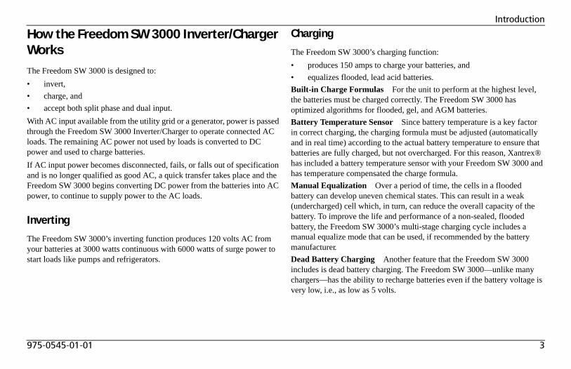
How the Freedom SW 3000 Inverter/Charger WorksThe Freedom SW 3000 is designed to:• invert,• charge, and • accept both split phase and dual input.With AC input available from the utility grid or a generator, power is passed through the Freedom SW 3000 Inverter/Charger to operate connected AC loads. The remaining AC power not used by loads is converted to DC power and used to charge batteries.If AC input power becomes disconnected, fails, or falls out of specification and is no longer qualified as good AC, a quick transfer takes place and the Freedom SW 3000 begins converting DC power from the batteries into AC power, to continue to supply power to the AC loads.
Inverting
The Freedom SW 3000’s inverting function produces 120 volts AC from your batteries at 3000 watts continuous with 6000 watts of surge power to start loads like pumps and refrigerators.
Charging
The Freedom SW 3000’s charging function:• produces 150 amps to charge your batteries, and• equalizes flooded, lead acid batteries.Built-in Charge Formulas For the unit to perform at the highest level, the batteries must be charged correctly. The Freedom SW 3000 has optimized algorithms for flooded, gel, and AGM batteries.Battery Temperature Sensor Since battery temperature is a key factor in correct charging, the charging formula must be adjusted (automatically and in real time) according to the actual battery temperature to ensure that batteries are fully charged, but not overcharged. For this reason, Xantrex® has included a battery temperature sensor with your Freedom SW 3000 and has temperature compensated the charge formula.Manual Equalization Over a period of time, the cells in a flooded battery can develop uneven chemical states. This can result in a weak (undercharged) cell which, in turn, can reduce the overall capacity of the battery. To improve the life and performance of a non-sealed, flooded battery, the Freedom SW 3000’s multi-stage charging cycle includes a manual equalize mode that can be used, if recommended by the battery manufacturer.Dead Battery Charging Another feature that the Freedom SW 3000 includes is dead battery charging. The Freedom SW 3000—unlike many chargers—has the ability to recharge batteries even if the battery voltage is very low, i.e., as low as 5 volts.
4 Freedom SW 3000 Owner’s Guide
Introduction
Load Management The Freedom SW 3000 has a built-in transfer relay that connects your inverter output or AC input from the utility grid or generator to your loads. Because the usual AC power sources such as campground outlets or small generators often have limited current availability, having the capability to manage your AC loads is extremely valuable. The Freedom SW 3000 provides a number of features to facilitate this:• The charger is power factor corrected to use AC current as efficiently
as possible and only requires 22 amps to provide rated charger output. Minimizing the AC current used by the charger means more current is available for your AC loads.
• Freedom SW 3000 has a power share feature which prioritizes your AC loads by reducing the charge current and maintaining the total input current to less than your breaker setting or the breaker setting.
• Occasionally, AC input sources have low voltage. To avoid loading these weak sources any further, the charger automatically reduces its AC current draw as the AC voltage approaches the minimum acceptable level.
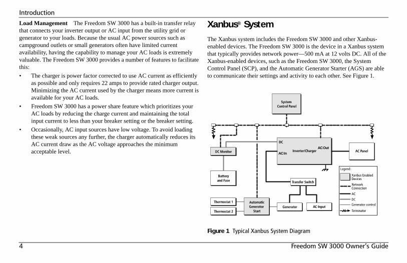
Xanbus® SystemThe Xanbus system includes the Freedom SW 3000 and other Xanbus-enabled devices. The Freedom SW 3000 is the device in a Xanbus system that typically provides network power—500 mA at 12 volts DC. All of the Xanbus-enabled devices, such as the Freedom SW 3000, the System Control Panel (SCP), and the Automatic Generator Starter (AGS) are able to communicate their settings and activity to each other. See Figure 1.
Figure 1 Typical Xanbus System Diagram
AC In
AC Out
975-0545-01-01 5
Introduction
The Xanbus-enabled designation means that this product works on a Xanbus network. Xanbus-enabled products are:• Easy to use. The Xanbus network simplifies operation and automates
routine tasks.• Reliable. Software control eliminates analog signalling errors.• Accurate. Digital information is less susceptible to interference and
line loss.• Upgradeable. Software upgrades mean your purchase will remain up
to date.For detailed instructions and a complete list of Xanbus-enabled devices, visit www.xantrex.com
Comprehensive Electronic ProtectionFreedom SW 3000 is approved to meet a number of safety standards including UL 458 and CSA C22.2 No. 107.1. See “Regulatory Approvals” on page 63 for more information.Freedom SW 3000 is equipped with numerous protection features to ensure safe operation.
Protection feature This feature…Battery over-voltage protection
Keeps the battery voltage from getting too high in charge mode. Shuts the inverter off in invert mode.
Battery under-voltage protection
Prevents inverter from discharging your batteries too low. The inverter doesn’t run if battery voltage is too low.
Over-temperature protection
Protects the unit from overheating by either derating (charge mode) or by shutting down (invert mode). See “Invert Power Derating versus Ambient Temperature” on page 64.
Automatic overload protection
Protects the unit from excessive loads. The unit will provide 6000 watts (twice the rated load) for up to ten seconds, and then protect itself by shutting down. See “Inverter Specifications” on page 61 for more information.
Short circuit protection Protects the unit by shutting it down.
6 Freedom SW 3000 Owner’s Guide
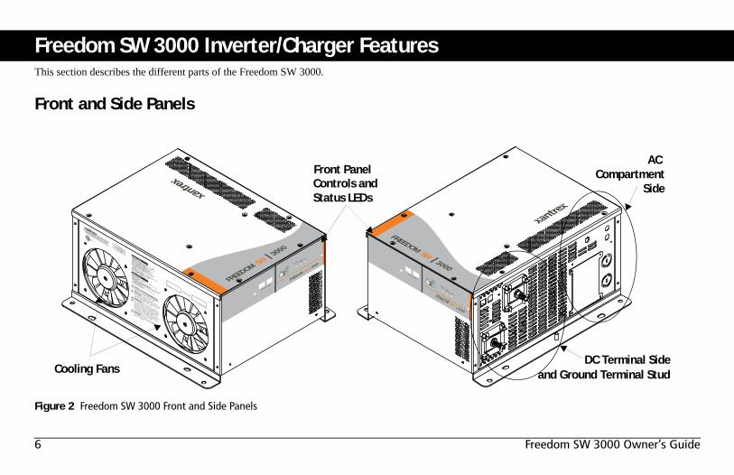
Freedom SW 3000 Inverter/Charger FeaturesThis section describes the different parts of the Freedom SW 3000.
Front and Side Panels
Figure 2 Freedom SW 3000 Front and Side Panels
FREEDOM SW 3000
Inverter
Reset
Enable
Inverter
AC/
On
Charge Fault
Xanbus Interfa
ce
FREEDOM SW 3000
Inverter
Reset Enable
Inverter AC/
On Charge Fault
Xanbus Interface
Date of Manufacture
Serial Number
CAUTION: To reduce the risk of fire, do not
cover or obstruct ventilation openings. Do not mount
in a zero-clearance compartment. Overheating may
result. Do not expose to rain or spray.
INSTALLATION REQUIREMENTS:
Mount this inverter/charger only in the orientations
specified in the installation guide provided.
WARNING: Shock hazard. Do not open. No
user serviceable parts. Energized from both AC and
DC sources. Disconnect all sources before servicing.
Use only ground-fault circuit interrupters (GFCI)
specified in the installation guide supplied. Other
types may fail to operate properly when connected to
this equipment. Refer to manual. Charge only
lead-acid batteries. Other battery types may burst
causing personal injury and damage.
Nominal DC Operating Voltage: 12 Vdc
Nominal AC Output Voltage: 120 Vac , 1Ø
Nominal AC Output Frequency: 60 Hz
Max. Continuous AC Output Current: 25 A
Max. Operating DC Input Current: 320 A
Max. Continuous AC Output at Nominal DC
Input: 3000 VA at 25°C
Max. Output Surge Power (5 s duration): 6000 VA
Max. DC Input Voltage: 16 Vdc
Max. Ambient Temperature: 50°C
Inverter Mode:
Nominal AC Input Voltage: 120 Vac , 60 Hz, 1Ø
Power Factor: > 0.95
Charging DC Output Voltage Range: 5.0 - 16.0 Vdc
Max. Continuous Battery Charger DC Current at
Nominal AC Input: 150 A
Max. AC Input Current: 30 A per line Split Phase,
30 A per line Dual
Charger Mode:
3000W SINEWAVE INVERTER/CHARGER
FSW3000815-3000
ModelNumberFGANumber
FREEDOM SW 3000
Designed in Canada
Assembled in China
DANGER: To reduce the risk of explosion, do not
install in an area in which ignition-protected
euipment is required.
UL 458CSA 107.1-01
3033614
FREEDOM SW 3000
FREEDOM SW 3000
AC
Cooling Fans
Front PanelControls andStatus LEDs
DC Terminal Side
CompartmentSide
and Ground Terminal Stud
975-0545-01-01 7
Freedom SW 3000 Inverter/Charger Features
Front and Side Panels
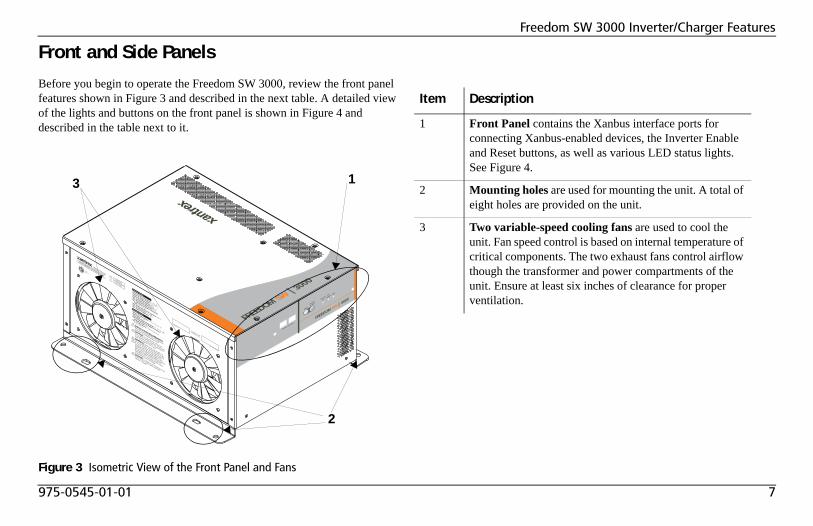
Before you begin to operate the Freedom SW 3000, review the front panel features shown in Figure 3 and described in the next table. A detailed view of the lights and buttons on the front panel is shown in Figure 4 and described in the table next to it.
Figure 3 Isometric View of the Front Panel and Fans
FREEDOM SW 3000
Inverter
Reset
Enable
Inverter
AC/
On
Charge Fault
Xanbus Interfa
ce
Date of Manufacture
Serial Number
CAUTION: To reduce the risk of fire, do not
cover or obstruct ventilation openings. Do not mount
in a zero-clearance compartment. Overheating may
result. Do not expose to rain or spray.
INSTALLATION REQUIREMENTS:
Mount this inverter/charger only in the orientations
specified in the installation guide provided.
WARNING: Shock hazard. Do not open. No
user serviceable parts. Energized from both AC and
DC sources. Disconnect all sources before servicing.
Use only ground-fault circuit interrupters (GFCI)
specified in the installation guide supplied. Other
types may fail to operate properly when connected to
this equipment. Refer to manual. Charge only
lead-acid batteries. Other battery types may burst
causing personal injury and damage.
Nominal DC Operating Voltage: 12 Vdc
Nominal AC Output Voltage: 120 Vac , 1Ø
Nominal AC Output Frequency: 60 Hz
Max. Continuous AC Output Current: 25 A
Max. Operating DC Input Current: 320 A
Max. Continuous AC Output at Nominal DC
Input: 3000 VA at 25°C
Max. Output Surge Power (5 s duration): 6000 VA
Max. DC Input Voltage: 16 Vdc
Max. Ambient Temperature: 50°C
Inverter Mode:
Nominal AC Input Voltage: 120 Vac , 60 Hz, 1Ø
Power Factor: > 0.95
Charging DC Output Voltage Range: 5.0 - 16.0 Vdc
Max. Continuous Battery Charger DC Current at
Nominal AC Input: 150 A
Max. AC Input Current: 30 A per line Split Phase,
30 A per line Dual
Charger Mode:
3000W SINEWAVE INVERTER/CHARGER
FSW3000815-3000
ModelNumberFGANumber
FREEDOM SW 3000
Designed in Canada
Assembled in China
DANGER: To reduce the risk of explosion, do not
install in an area in which ignition-protected
euipment is required.
UL 458CSA 107.1-01
3033614
FREEDOM SW 3000
2
13
Item Description
1 Front Panel contains the Xanbus interface ports for connecting Xanbus-enabled devices, the Inverter Enable and Reset buttons, as well as various LED status lights. See Figure 4.
2 Mounting holes are used for mounting the unit. A total of eight holes are provided on the unit.
3 Two variable-speed cooling fans are used to cool the unit. Fan speed control is based on internal temperature of critical components. The two exhaust fans control airflow though the transformer and power compartments of the unit. Ensure at least six inches of clearance for proper ventilation.
8 Freedom SW 3000 Owner’s Guide
Freedom SW 3000 Inverter/Charger Features
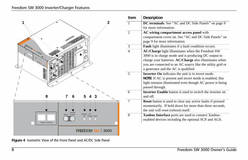
Figure 4 Isometric View of the Front Panel and AC/DC Side Panel
FREEDOM SW 3000
Inverter Reset Enable Inverter AC/
On Charge Fault
Xanbus Interface
FREEDOM SW 3000
Inverter
Reset Enable
Inverter AC/
On Charge Fault
Xanbus Interface
FREEDOM SW 3000
3
1
4
2
5678
Item Description1 DC terminals. See “AC and DC Side Panels” on page 9
for more information.2 AC wiring compartment access panel with
compartment cover on. See “AC and DC Side Panels” on page 9 for more information.
3 Fault light illuminates if a fault condition occurs.4 AC/Charge light illuminates when the Freedom SW
3000 is in charge mode and is producing DC output to charge your batteries. AC/Charge also illuminates when you are connected to an AC source like the utility grid or a generator and the AC is qualified.
5 Inverter On indicates the unit is in invert mode. NOTE: If AC is present and invert mode is enabled, this light remains illuminated even though AC power is being passed through.
6 Inverter Enable button is used to switch the inverter on and off.
7 Reset button is used to clear any active faults if pressed momentarily. If held down for more than three seconds, the unit will reset (reboot) itself.
8 Xanbus Interface ports are used to connect Xanbus-enabled devices including the optional SCP and AGS.
975-0545-01-01 9
Freedom SW 3000 Inverter/Charger Features
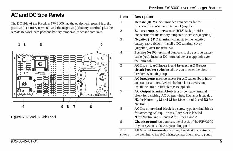
AC and DC Side PanelsThe DC side of the Freedom SW 3000 has the equipment ground lug, the positive (+) battery terminal, and the negative (–) battery terminal plus the remote network com port and battery temperature sensor com port.
Figure 5 AC and DC Side Panel
AC INPU
TLIN
E 1
REM BTS
Wiring box cover must be in place duringuse to reduce risk of injury to persons
AC INPU
TLIN
E 2
INVERTER
AC OU
TPUT
ACOUT
ACIN
AC GROUNDS(BEHIND COVER)
WARNING: INCORRECT BATTERY POLA RITY W
ILL CAUSE D A M
AGE TO
UN
IT.
5
7 6
321
4 89
Item Description1 Remote (REM) jack provides connection for the
Freedom Sine Wave remote panel (supplied).2 Battery temperature sensor (BTS) jack provides
connection for the battery temperature sensor (supplied).3 Negative (–) DC terminal connects to the negative
battery cable (black). Install a DC terminal cover (supplied) over the terminal.
4 Positive (+) DC terminal connects to the positive battery cable (red). Install a DC terminal cover (supplied) over the terminal.
5 AC Input 1, AC Input 2, and Inverter AC Output circuit breaker switches allow you to reset the circuit breakers when they trip.
6 AC knockouts provide access for AC cables (both input and output wiring). Detach the knockout covers and install the strain-relief clamps (supplied).
7 AC Output terminal block is a screw-type terminal block for attaching AC output wires. Each slot is labeled N1 for Neutral 1, L1 and L2 for Lines 1 and 2, and N2 for Neutral 2.
8 AC Input terminal block is a screw-type terminal block for attaching AC input wires. Each slot is labeled N for Neutral and L1 and L2 for Lines 1 and 2.
9 Chassis ground lug connects the chassis of the FSW3000 to your system’s chassis grounding point.
Not shown
All Ground terminals are along the tab at the bottom of the opening to the AC wiring compartment access panel.
10 Freedom SW 3000 Owner’s Guide
Freedom SW 3000 Inverter/Charger Features
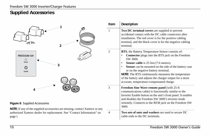
Supplied Accessories
NOTE: If any of the supplied accessories are missing, contact Xantrex or any authorized Xantrex dealer for replacement. See “Contact Information” on page i.
Figure 6 Supplied Accessories
3
1
4
2
Item Description
1 Two DC terminal covers are supplied to prevent accidental contact with the DC cable connectors after installation. The red cover is for the positive cabling terminal, and the black cover is for the negative cabling terminal.
2 BTS, the Battery Temperature Sensor consists of:• Connector plugs into the BTS jack on the Freedom
SW 3000.• Sensor cable is 25 feet (7.6 meters).• Sensor can be mounted on the side of the battery case
or on the negative battery terminal.NOTE: The BTS continuously measures the temperature of the battery and adjusts the charger output for a more accurate, temperature-compensated charge.
3 Freedom Sine Wave remote panel (with 25-ft communications cable) is functionally similar to the Inverter Enable button on the unit’s front panel. It enables and disables the Freedom SW 3000’s inverter mode remotely. Connects to the REM jack on the Freedom SW 3000.
4 Two sets of nuts and washers are used to secure DC cable ends to the DC terminals.
975-0545-01-01 11
Freedom SW 3000 Inverter/Charger Features
Optional System Accessories and Network Components
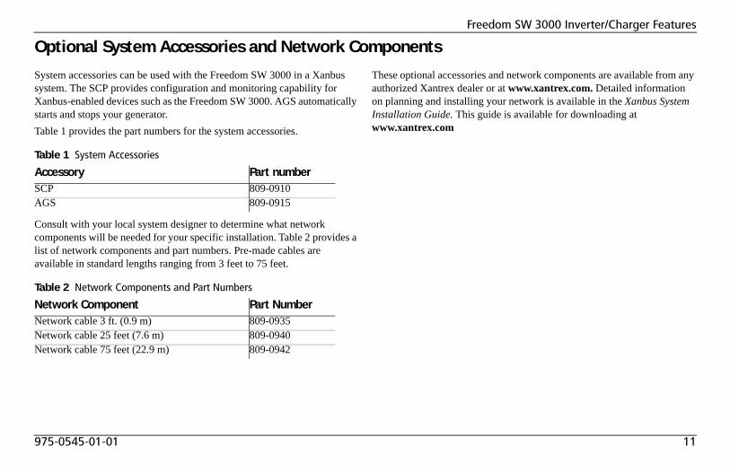
System accessories can be used with the Freedom SW 3000 in a Xanbus system. The SCP provides configuration and monitoring capability for Xanbus-enabled devices such as the Freedom SW 3000. AGS automatically starts and stops your generator.Table 1 provides the part numbers for the system accessories.
Consult with your local system designer to determine what network components will be needed for your specific installation. Table 2 provides a list of network components and part numbers. Pre-made cables are available in standard lengths ranging from 3 feet to 75 feet.
These optional accessories and network components are available from any authorized Xantrex dealer or at www.xantrex.com. Detailed information on planning and installing your network is available in the Xanbus System Installation Guide. This guide is available for downloading at www.xantrex.com
Table 1 System Accessories
Accessory Part numberSCP 809-0910AGS 809-0915
Table 2 Network Components and Part Numbers
Network Component Part NumberNetwork cable 3 ft. (0.9 m) 809-0935Network cable 25 feet (7.6 m) 809-0940Network cable 75 feet (22.9 m) 809-0942
12 Freedom SW 3000 Owner’s Guide
Operating The Freedom SW 3000This section contains detailed information and procedures for using your Freedom SW 3000.If you’re using the SCP to operate or monitor the status of the unit, also refer to the System Control Panel Owner’s Guide.
Operating the Freedom SW 3000 with the Optional System Control Panel (SCP)The SCP provides operating, configuration, and monitoring capability for your Xanbus system.The System Control Panel:• Monitors activity throughout your onboard power system.• Displays the latest information about your inverter/charger, battery
charge level, battery charge output, and generator start and stop activity.
• Displays the settings for each Xanbus-enabled device in the system.• Enables you to adjust the settings for each Xanbus-enabled device in
the system.• Preserves all of its settings if system power is interrupted. After power
is restored, you don’t have to reconfigure the SCP or any of the Xanbus-enabled devices connected to it.
This section provides information on operating the Freedom SW 3000 with the System Control Panel. Please refer to the System Control Panel Owner’s Guide for complete information on using the System Control Panel.
LIMITATIONS ON USE• Do not use in connection with life support systems or other medical
equipment or devices.• Do not use in ambulances or other life-saving emergency vehicles.Failure to follow these instructions can result in death or serious injury.
975-0545-01-01 13
Operating The Freedom SW 3000
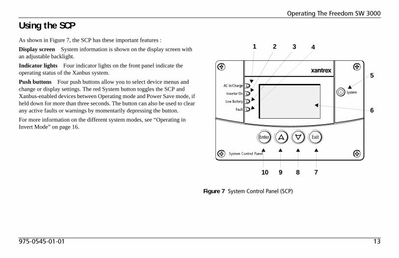
Using the SCPAs shown in Figure 7, the SCP has these important features :Display screen System information is shown on the display screen with an adjustable backlight.Indicator lights Four indicator lights on the front panel indicate the operating status of the Xanbus system.Push buttons Four push buttons allow you to select device menus and change or display settings. The red System button toggles the SCP and Xanbus-enabled devices between Operating mode and Power Save mode, if held down for more than three seconds. The button can also be used to clear any active faults or warnings by momentarily depressing the button. For more information on the different system modes, see “Operating in Invert Mode” on page 16.
Figure 7 System Control Panel (SCP)
21 43
10 9 8 7
5
6
14 Freedom SW 3000 Owner’s Guide
Operating The Freedom SW 3000
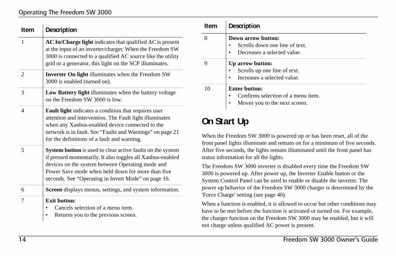
On Start UpWhen the Freedom SW 3000 is powered up or has been reset, all of the front panel lights illuminate and remain on for a minimum of five seconds. After five seconds, the lights remain illuminated until the front panel has status information for all the lights.The Freedom SW 3000 inverter is disabled every time the Freedom SW 3000 is powered up. After power up, the Inverter Enable button or the System Control Panel can be used to enable or disable the inverter. The power up behavior of the Freedom SW 3000 charger is determined by the 'Force Charge' setting (see page 40).When a function is enabled, it is allowed to occur but other conditions may have to be met before the function is activated or turned on. For example, the charger function on the Freedom SW 3000 may be enabled, but it will not charge unless qualified AC power is present.
Item Description
1 AC In/Charge light indicates that qualified AC is present at the input of an inverter/charger. When the Freedom SW 3000 is connected to a qualified AC source like the utility grid or a generator, this light on the SCP illuminates.
2 Inverter On light illuminates when the Freedom SW 3000 is enabled (turned on).
3 Low Battery light illuminates when the battery voltage on the Freedom SW 3000 is low.
4 Fault light indicates a condition that requires user attention and intervention. The Fault light illuminates when any Xanbus-enabled device connected to the network is in fault. See “Faults and Warnings” on page 21 for the definitions of a fault and warning.
5 System button is used to clear active faults on the system if pressed momentarily. It also toggles all Xanbus-enabled devices on the system between Operating mode and Power Save mode when held down for more than five seconds. See “Operating in Invert Mode” on page 16.
6 Screen displays menus, settings, and system information.
7 Exit button:• Cancels selection of a menu item.• Returns you to the previous screen.
8 Down arrow button:• Scrolls down one line of text.• Decreases a selected value.
9 Up arrow button:• Scrolls up one line of text.• Increases a selected value.
10 Enter button:• Confirms selection of a menu item.• Moves you to the next screen.
Item Description
975-0545-01-01 15
Operating The Freedom SW 3000
System Start-up Check
To test inverting and charging from the Freedom SW 3000 front panel:1. Disconnect AC power from inverter input by opening the breaker or
disconnect. Press the Inverter Enable button on the Freedom SW 3000. The Inverter On light illuminates.
2. Place a load on the inverter. For example, plug a 100 watt light bulb into an outlet that the inverter is powering and make sure it works. The inverter should run the load using battery power.
3. To test the charger, reconnect the AC input power to allow AC to the AC input. The AC/Charger On light should illuminate after a brief delay. Any AC loads previously powered by the inverter will also work at this time.
4. Remove the AC input power. The inverter/charger should transfer to invert mode immediately. (The transfer relay will make a clicking sound and the Inverter On light will illuminate.) Loads should continue to operate uninterrupted.
If any part of this test fails, determine the cause before using the unit. Consult the “Troubleshooting” chapter starting on page 45.
Viewing the Firmware Revision NumberYou may need to view the firmware revision number of the Freedom SW 3000 when troubleshooting the unit with authorized service personnel.To view the firmware revision number:1. On the Select Device menu, use the down arrow button to highlight
System and press Enter.The System Settings menu appears.
2. Press the down arrow button to highlight View Device info and press Enter.The Device Info screen appears.
3. Press the down arrow button until the Freedom SW 3000 screen appears.The number opposite “F/W Rev.” is the firmware revision number.
4. Press Exit to return to the System Settings menu.
IMPORTANT: Review the “Important Safety Instructions” on page iv before operating the inverter/charger.
16 Freedom SW 3000 Owner’s Guide
Operating The Freedom SW 3000
Operating in Invert Mode
Once the inverter/charger is installed, you can operate it in invert mode.To operate in invert mode from the front panel:1. Press the Inverter Enable button on the Freedom SW 3000.2. If external AC is present, the External AC light illuminates. If AC is
present and you want to operate the inverter, remove AC so the inverter turns on.
◆ Once the Inverter On light is on, the Freedom SW 3000 inverter is ready to deliver AC power to the loads.
To operate the inverter with the System Control Panel, refer to “Operating the Freedom SW 3000 with the Optional System Control Panel (SCP)” on page 12.
Operating Limits for Inverter Operation
Temperature The Freedom SW 3000 produces 120 volts AC at 3000 watts continuously in room temperature. The Freedom SW 3000 can deliver this power in an ambient (surrounding) temperature up to 77 °F (25 °C). In higher ambient temperatures, if the loads draw full power for an extended period of time, the unit may shut down to protect itself against overheating.
As with all inverters, the amount of continuous power that the Freedom SW 3000 can deliver without overheating is limited by the ambient air temperature. The Freedom SW 3000 will operate and deliver its continuous power rating at higher temperatures, but the ambient temperature as well as the input voltage from the battery will limit the extent to which the unit can run continuously.The Freedom SW 3000 has 6000-watt surge for ten seconds. Operating the inverter/charger in conditions outside of power and temperature limits, however, will result in thermal shutdown and/or significantly decreased performance. In addition, operation in this range is outside the ratings covered by the regulatory approvals of the product. See “Invert Power Derating versus Ambient Temperature” on page 64.Difficulty on starting loads The inverter/charger should be able to operate all AC loads rated at or below its power rating. Some high horsepower induction motors used in pumps and other motor-operated equipment require very high surge currents to start, and the inverter/charger may have difficulty starting these loads. See “Inverter Applications” on page 54. If you have problems starting certain loads, ensure that:• the battery connections are tight and clean,• the DC cabling is no longer than the recommended length. Refer to the
FSW3000 Sine Wave Inverter/Charger Installation Guide for this information,
• the AC wiring is of recommended size. Refer to the FSW3000 Sine Wave Inverter/Charger Installation Guide for this information, and
• the battery is of sufficient capacity and is fully charged.
IMPORTANT: Review the “Important Safety Instructions” on page iv before operating the inverter/charger.
IMPORTANT: If you are having problems with any of your loads, refer to “Inverter Applications” on page 54.
975-0545-01-01 17
Operating The Freedom SW 3000
Operating in Charger Mode
NOTES:• Study and follow all of the battery manufacturer's specific precautions,
such as removing or not removing cell caps while charging, whether equalization is acceptable for your battery, and recommended rates of charge.
• For flooded non-sealed batteries, add distilled water in each cell until battery acid reaches the level specified by the battery manufacturer. This helps to purge excessive gas from cells. Do not overfill. For a battery without removable cell caps, carefully follow manufacturer's instructions.
To operate the Freedom SW 3000 in charger mode from the front panel:1. Connect AC input power.
The charger automatically starts up when qualified AC power is connected if the charger is enabled, or the charger is disabled but the Force Charge enable override is On. See “Force Charge” on page 23.
• The batteries are charged according to the two-stage or three-stage formula you have selected on the SCP. See “Battery Charging Reference” on page 55 for more information on two-stage or three-stage charging.
• You can interrupt the charge cycle any time you desire by disabling the charger from the SCP.
• To maintain optimal performance in flooded batteries, an occasional equalize cycle may be required. See “Operating in Equalization Mode” on page 18.
• While the batteries are being charged, you can monitor which stage they are in from the front panel of the Freedom SW 3000 or from the SCP.
2. To operate the charger with the SCP, refer to “Configuration” on page 25.
Charger Operation with Battery TemperatureSensor (BTS)
Since battery temperature is a key factor in correct charging, the charging formula must be adjusted (automatically and in real time) according to the actual battery temperature to ensure that batteries are fully charged, but not overcharged. For this reason, Xantrex has included a BTS (see Figure 6) with your Freedom SW 3000 Inverter/Charger and has temperature compensated the charge formula.The BTS continuously measures the temperature of the battery and adjusts charger output for a more accurate, temperature-compensated charge.
EXPOSURE TO CHEMICALS AND GASES HAZARD• Make sure the area around the battery is well ventilated.• Make sure the voltage of the batteries matches the output voltage of
the inverter/charger.Failure to follow these instructions can result in death or serious injury.
18 Freedom SW 3000 Owner’s Guide
Operating The Freedom SW 3000
When batteries are cold, their chemical reaction is sluggish, meaning they don’t absorb charge as easily. Thus a charge level optimized for room temperature will not charge the batteries sufficiently if they are cold. The charger must compensate by increasing its voltage to achieve the compensated equivalent of a room temperature charge. If the batteries are hot, the chemical reaction is hyperactive and they absorb energy too easily; thus a standard room-temperature charge would tend to overcharge a hot battery. Therefore, the charger compensates by reducing its voltage.The BTS automatically, and in real time, makes adjustments to the charger’s voltage setpoints to properly charge your batteries. The actual charge compensation formula can be found on “Charger Specifications” on page 61.
If a BTS is not present, the Freedom SW 3000 uses the hot setting, the default value, unless the setting has been adjusted during configuration. Charging may not be effective at extreme temperatures. See “Charger Specifications” on page 61.
Operating in Equalization Mode
NOTES:• Equalize mode is automatically disabled if you have selected “Gel” or
“AGM” as the battery type.• As a general rule, do not equalize a lead-acid battery unless there are
provisions to add water to it and the manufacturer recommends equalization.
IMPORTANT: It is normal to see a voltage that is different than the specified setpoint when charging if the battery case temperature is above or below 77 °F (25 °C).
EXPOSURE TO CHEMICALS AND GASES HAZARD• Make sure the area around the battery is well ventilated.• Equalization generates explosive gases.Failure to follow these instructions can result in death or serious injury.
RISK OF DAMAGE TO BATTERIES• Do not equalize sealed lead-acid batteries and gel batteries.• Only flooded (wet) lead-acid batteries should be equalized.• Never equalize a lead-acid battery more than necessary. Always
check the electrolyte level before AND after equalization. Fill with distilled water per the battery manufacturer’s recommendation.
Failure to follow these instructions can damage the unit and/or damage other equipment.
975-0545-01-01 19
Operating The Freedom SW 3000
Follow the battery manufacturer’s recommendations for equalizing your batteries. As a guide, a heavily used flooded battery may need to be equalized once a month, and a battery in light service may only need to be equalized every two to four months.Measure the specific gravity (S.G.) of each cell using a hydrometer. For fully charged lead-acid batteries, the reading should be approximately 1.265. Low specific gravity after charging or a 0.25 difference from cell to cell indicates the need for equalization.
Equalizing Batteries
To equalize your batteries:1. Turn off or disconnect all loads on the battery.
The voltage applied to the battery during equalization may damage your electronic equipment. As well, equalization won’t proceed correctly if loads are drawing current from the battery.
2. Check electrolyte level.Fill with distilled water if the electrolyte level is low.
3. To request the equalization charge, ensure the Charger is enabled. 4. On the SCP, select Equalize on the Freedom SW 3000 home menu.
For detailed information on configuring this setting, refer to “Equalize” on page 34.
5. When equalization is finished, check the battery electrolyte level. Top up as necessary with distilled water only and recheck the specific gravity as specified by the battery manufacturer.
Terminating the Equalization Process
The equalization process can be terminated in three ways:• user cancellation from the SCP, as shown in Figure 24 on page 36,• inverter/charger cancellation if AC is removed or the charger is
disabled, or• a successful completion of the equalization process.
RISK OF DAMAGE TO DC LOAD EQUIPMENTEqualization voltage may be as high as 15.8 volts DC. Disconnect sensitive loads from the battery before equalizing.
Failure to follow these instructions can damage the unit and/or damage other equipment.
IMPORTANT: Equalization will be carried out after an absorption charge. Equalization only runs for 60 minutes and may need to be restarted if the specific gravity is still uneven.
20 Freedom SW 3000 Owner’s Guide
Operating The Freedom SW 3000
Operating Limits for Charger Operation
The maximum output current for the Freedom SW 3000 is 150 amps. You can reduce the total output if you change the “Max Chg Rate” setting on the Freedom SW 3000 Advanced Menu or the maximum “Power Share”setting on the Freedom SW 3000 Basic Menu.The charger can operate over an AC input range of 90–135 volts AC. This is the default setting and can be adjusted to 85–145 volts AC as a maximum range and to 110–120 volts AC as a minimum range.This wide range allows the Freedom SW 3000 to charge your batteries even when incoming AC voltage is less than ideal.Power Share The Freedom SW 3000 charger uses AC input line 1 to charge the batteries. The Freedom SW 3000 charger shares incoming power with AC loads on line 1 only. The AC loads have priority, which means that the charger will reduce its output with large AC loads and increase the output again when the AC load decreases. The regulatory maximum for continuous AC loads is 80% of the breaker rating that the loads are connected to.The Freedom SW 3000 senses pass-through current going to the AC load. The difference between the pass-through (load) and 80% of the Power Share setting is the current that is available for charging the batteries.For example, if the AC input of the Freedom SW 3000 is from an AC panel with a 30A breaker, the Power Share setting on the SCP should be selected as 30A. Based on this, the charger will control the charge current so that the total current draw is equal to or less than 24A in this case. Should the load current be more than about 24A, the charger output will reduce to 0A, but the Freedom SW 3000 will continue to supply the loads. The Freedom SW 3000 will continue to pass-through power to the loads, even if the load
current exceeds the Power Share setting. In this case, it will be up to the user to remove/disconnect loads if tripping the AC input breaker supplying the Freedom SW 3000 is to be avoided.
975-0545-01-01 21
Operating The Freedom SW 3000
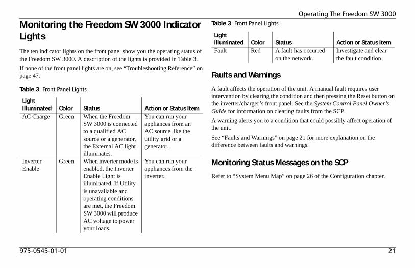
Monitoring the Freedom SW 3000 Indicator LightsThe ten indicator lights on the front panel show you the operating status of the Freedom SW 3000. A description of the lights is provided in Table 3.If none of the front panel lights are on, see “Troubleshooting Reference” on page 47. Faults and Warnings
A fault affects the operation of the unit. A manual fault requires user intervention by clearing the condition and then pressing the Reset button on the inverter/charger’s front panel. See the System Control Panel Owner’s Guide for information on clearing faults from the SCP.A warning alerts you to a condition that could possibly affect operation of the unit.See “Faults and Warnings” on page 21 for more explanation on the difference between faults and warnings.
Monitoring Status Messages on the SCP
Refer to “System Menu Map” on page 26 of the Configuration chapter.
Table 3 Front Panel Lights
Light Illuminated Color Status Action or Status ItemAC Charge Green When the Freedom
SW 3000 is connected to a qualified AC source or a generator, the External AC light illuminates.
You can run your appliances from an AC source like the utility grid or a generator.
Inverter Enable
Green When inverter mode is enabled, the Inverter Enable Light is illuminated. If Utility is unavailable and operating conditions are met, the Freedom SW 3000 will produce AC voltage to power your loads.
You can run your appliances from the inverter.
Fault Red A fault has occurred on the network.
Investigate and clear the fault condition.
Table 3 Front Panel Lights
Light Illuminated Color Status Action or Status Item
22 Freedom SW 3000 Owner’s Guide
Operating The Freedom SW 3000
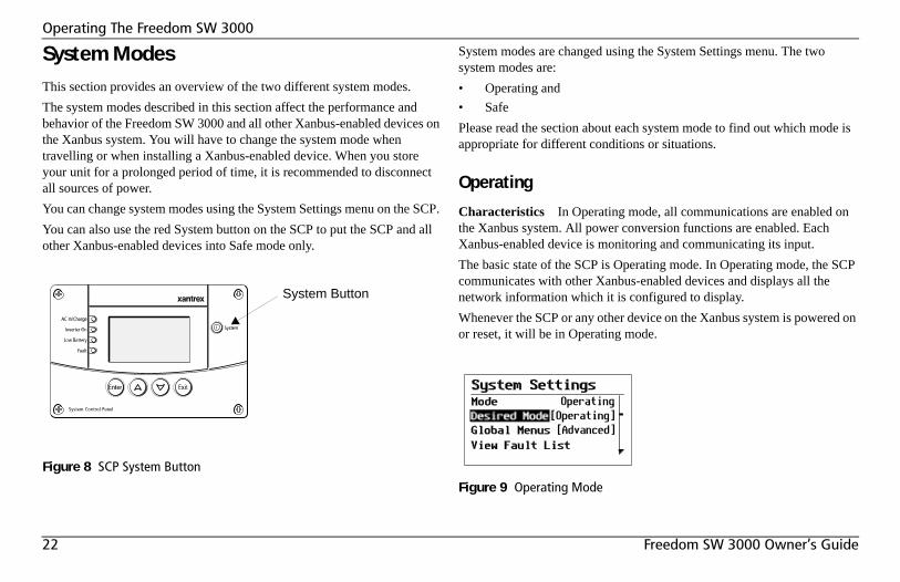
System ModesThis section provides an overview of the two different system modes.The system modes described in this section affect the performance and behavior of the Freedom SW 3000 and all other Xanbus-enabled devices on the Xanbus system. You will have to change the system mode when travelling or when installing a Xanbus-enabled device. When you store your unit for a prolonged period of time, it is recommended to disconnect all sources of power.You can change system modes using the System Settings menu on the SCP. You can also use the red System button on the SCP to put the SCP and all other Xanbus-enabled devices into Safe mode only.
System modes are changed using the System Settings menu. The two system modes are:• Operating and• SafePlease read the section about each system mode to find out which mode is appropriate for different conditions or situations.
Operating
Characteristics In Operating mode, all communications are enabled on the Xanbus system. All power conversion functions are enabled. Each Xanbus-enabled device is monitoring and communicating its input.The basic state of the SCP is Operating mode. In Operating mode, the SCP communicates with other Xanbus-enabled devices and displays all the network information which it is configured to display.Whenever the SCP or any other device on the Xanbus system is powered on or reset, it will be in Operating mode.
Figure 8 SCP System Button
System Button
Figure 9 Operating Mode
975-0545-01-01 23
Operating The Freedom SW 3000
Safe
Characteristics Selecting Safe mode stops the generator (if it is running) and puts the SCP (and all Xanbus-enabled devices) into Safe mode. While in Safe mode, the SCP remains powered, “listening” to and reporting its status to the network. However, the output power of all Xanbus-enabled devices is disabled and all inverting, charging, and generator starting activity stops. In Safe mode, the Freedom SW 3000 will not transfer AC power from a source.In Safe mode, the Freedom SW 3000 continues to communicate, but the inverting and charging functions are disabled.When to use Use Safe mode when you are adding or removing devices from the network. Authorized service personnel must also put the SCP in Safe mode before performing software upgrades and diagnostics with the Xantrex Diagnostic Tool.If the SCP is powered off while in Safe mode, it will be in Safe mode when it is powered up again.To return to Operating mode:◆ On the System Settings menu, under Desired Mode, select
“Operating.”Putting the System into Safe Mode When you are installing or removing devices from the Xanbus system, putting the system into Safe mode prevents unexpected behavior.
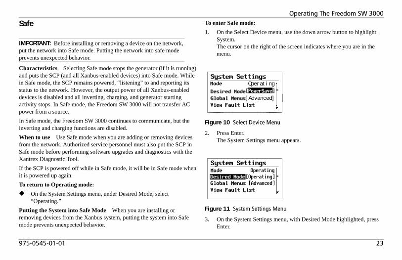
To enter Safe mode:1. On the Select Device menu, use the down arrow button to highlight
System.The cursor on the right of the screen indicates where you are in the menu.
2. Press Enter.The System Settings menu appears.
3. On the System Settings menu, with Desired Mode highlighted, press Enter.
IMPORTANT: Before installing or removing a device on the network, put the network into Safe mode. Putting the network into safe mode prevents unexpected behavior.
Figure 10 Select Device Menu
Figure 11 System Settings Menu
Operating
[Advanced]
24 Freedom SW 3000 Owner’s Guide
Operating The Freedom SW 3000
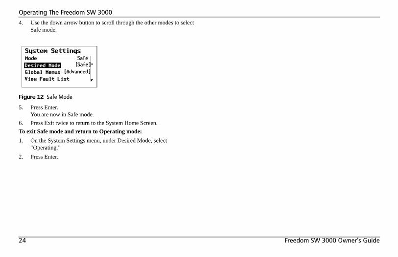
4. Use the down arrow button to scroll through the other modes to select Safe mode.
5. Press Enter.You are now in Safe mode.
6. Press Exit twice to return to the System Home Screen.To exit Safe mode and return to Operating mode:1. On the System Settings menu, under Desired Mode, select
“Operating.”2. Press Enter.
Figure 12 Safe Mode
975-0545-01-01 25
ConfigurationThis section contains information about all configurable settings and procedures for the Freedom SW 3000.It provides information on using the SCP to configure the Freedom SW 3000 settings. Please refer to the System Control Panel Owner’s Guide for detailed information on how to use the SCP.
System Control PanelThe System Control Panel (SCP) provides configuration and monitoring capability for all Xanbus-enabled devices on the network. All changes to the configuration of the Freedom SW 3000 are made with the SCP. See “Using the SCP” on page 13.The front panel of the Freedom SW 3000 provides limited control, including reset; charger enable and disable; and inverter enable and disable. Enabling a function When a function is enabled, it is allowed to occur but other conditions may have to be met before the function is activated or turned on. For example, the charger function on the Freedom SW 3000 may be enabled, but it will not charge unless qualified AC power is present.Disabling a function When a function is disabled, it is not allowed to occur and if it is occurring, it is terminated. Regardless of other conditions, the function will not be activated. For example, even if AC power is present, if the charger is disabled, the unit will not charge.
NOTE: These functions on the front panel can also be controlled from the SCP.
26 Freedom SW 3000 Owner’s Guide
Configuration
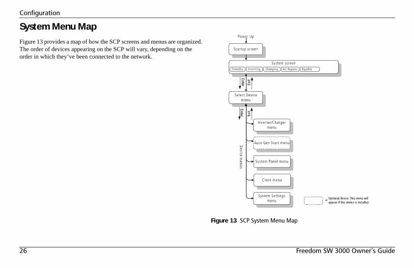
System Menu MapFigure 13 provides a map of how the SCP screens and menus are organized. The order of devices appearing on the SCP will vary, depending on the order in which they’ve been connected to the network.
Figure 13 SCP System Menu Map
975-0545-01-01 27
Configuration
Viewing the System Screen
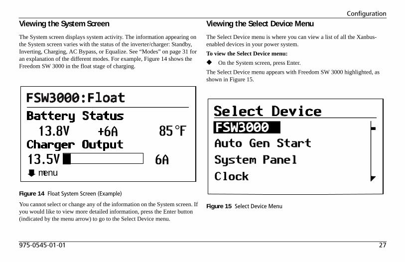
The System screen displays system activity. The information appearing on the System screen varies with the status of the inverter/charger: Standby, Inverting, Charging, AC Bypass, or Equalize. See “Modes” on page 31 for an explanation of the different modes. For example, Figure 14 shows the Freedom SW 3000 in the float stage of charging.
You cannot select or change any of the information on the System screen. If you would like to view more detailed information, press the Enter button (indicated by the menu arrow) to go to the Select Device menu.
Viewing the Select Device Menu
The Select Device menu is where you can view a list of all the Xanbus-enabled devices in your power system.To view the Select Device menu:◆ On the System screen, press Enter.The Select Device menu appears with Freedom SW 3000 highlighted, as shown in Figure 15.
Figure 14 Float System Screen (Example)
menu
Figure 15 Select Device Menu
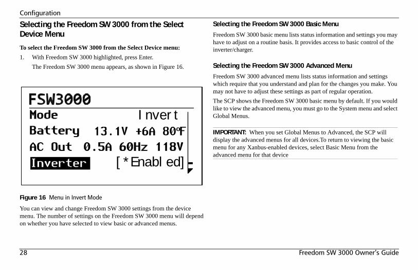
28 Freedom SW 3000 Owner’s Guide
Configuration
Selecting the Freedom SW 3000 from the Select Device Menu
To select the Freedom SW 3000 from the Select Device menu:1. With Freedom SW 3000 highlighted, press Enter.
The Freedom SW 3000 menu appears, as shown in Figure 16.
You can view and change Freedom SW 3000 settings from the device menu. The number of settings on the Freedom SW 3000 menu will depend on whether you have selected to view basic or advanced menus.
Selecting the Freedom SW 3000 Basic Menu
Freedom SW 3000 basic menu lists status information and settings you may have to adjust on a routine basis. It provides access to basic control of the inverter/charger.
Selecting the Freedom SW 3000 Advanced Menu
Freedom SW 3000 advanced menu lists status information and settings which require that you understand and plan for the changes you make. You may not have to adjust these settings as part of regular operation.The SCP shows the Freedom SW 3000 basic menu by default. If you would like to view the advanced menu, you must go to the System menu and select Global Menus.
Figure 16 Menu in Invert Mode
Invert
[*Enabled]
IMPORTANT: When you set Global Menus to Advanced, the SCP will display the advanced menus for all devices.To return to viewing the basic menu for any Xanbus-enabled devices, select Basic Menu from the advanced menu for that device
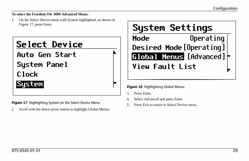
975-0545-01-01 29
ConfigurationTo select the Freedom SW 3000 Advanced Menu:1. On the Select Device menu with System highlighted, as shown in
Figure 17, press Enter.
2. Scroll with the down arrow button to highlight Global Menus.
3. Press Enter.4. Select Advanced and press Enter.5. Press Exit to return to Select Device menu.Figure 17 Highlighting System on the Select Device Menu
Figure 18 Highlighting Global Menus
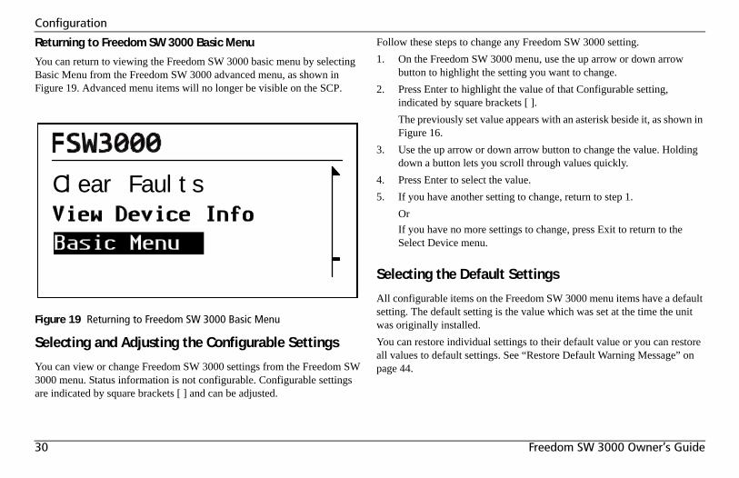
30 Freedom SW 3000 Owner’s Guide
Configuration
Returning to Freedom SW 3000 Basic Menu
You can return to viewing the Freedom SW 3000 basic menu by selecting Basic Menu from the Freedom SW 3000 advanced menu, as shown in Figure 19. Advanced menu items will no longer be visible on the SCP.
Selecting and Adjusting the Configurable Settings
You can view or change Freedom SW 3000 settings from the Freedom SW 3000 menu. Status information is not configurable. Configurable settings are indicated by square brackets [ ] and can be adjusted.
Follow these steps to change any Freedom SW 3000 setting.1. On the Freedom SW 3000 menu, use the up arrow or down arrow
button to highlight the setting you want to change.2. Press Enter to highlight the value of that Configurable setting,
indicated by square brackets [ ].The previously set value appears with an asterisk beside it, as shown in Figure 16.
3. Use the up arrow or down arrow button to change the value. Holding down a button lets you scroll through values quickly.
4. Press Enter to select the value.5. If you have another setting to change, return to step 1.
OrIf you have no more settings to change, press Exit to return to the Select Device menu.
Selecting the Default Settings
All configurable items on the Freedom SW 3000 menu items have a default setting. The default setting is the value which was set at the time the unit was originally installed.You can restore individual settings to their default value or you can restore all values to default settings. See “Restore Default Warning Message” on page 44.
Figure 19 Returning to Freedom SW 3000 Basic Menu
Clear Faults
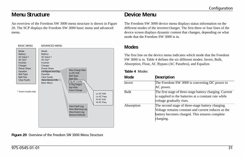
975-0545-01-01 31
Configuration
Menu StructureAn overview of the Freedom SW 3000 menu structure is shown in Figure 20. The SCP displays the Freedom SW 3000 basic menu and advanced menu.
Device MenuThe Freedom SW 3000 device menu displays status information on the different modes of the inverter/charger. The first three or four lines of the device screen displays dynamic content that changes, depending on what mode that the Freedom SW 3000 is in.
Modes
The first line on the device menu indicates which mode that the Freedom SW 3000 is in. Table 4 defines the six different modes: Invert, Bulk, Absorption, Float, AC Bypass (AC Passthru), and Equalize.
Figure 20 Overview of the Freedom SW 3000 Menu Structure
BASIC MENU ADVANCED MENU
ModeBatteryAC Input 1AC Out*InverterChargerPower ShareEqualizeBatt TypeBatt SizeClear Faults
Lo AC VoltLo AC FreqHi AC VoltHi AC Freq
View Fault LogView Warning LogView Event LogRestore Defaults
ModeBatteryAC Input 1AC Out*InverterChargerPower ShareC re Inv/ChgEqualizeClear FaultsView Device InfoBasic Menu
* invert mode only
Max Charge RateLo DC VoltBatt TypeBatt SizeCfg AC Limits# Chg StagesEqz VoltsForce Charge
Table 4 Modes
Mode DescriptionInvert The Freedom SW 3000 is converting DC power to
AC power.Bulk The first stage of three-stage battery charging. Current
is supplied to the batteries at a constant rate while voltage gradually rises.
Absorption The second stage of three-stage battery charging. Voltage remains constant and current reduces as the battery becomes charged. This ensures complete charging.
32 Freedom SW 3000 Owner’s Guide
Configuration
Battery
The second line of the device screen indicates the status of the battery. This line displays the volts (V); current (A) as either (+) positive amps (indicating that the battery is charging) or (–) negative amps (indicating the battery is discharging because you’re inverting); and battery temperature in either °F or °C.
AC Input1
When the Freedom SW 3000 has external AC input connected, these AC display lines indicate the status of the AC input. Each AC display line shows the values for current (A), frequency (Hz), and the AC voltage in (V).
AC Out
This line is displayed only when the Freedom SW 3000 is in invert mode. This line indicates the AC output on both output lines (1 and 2) and shows the values for total current (A), the frequency (Hz), and the AC voltage in (V).
Float The third stage of three-stage battery charging. After the batteries reach full charge, charging voltage is reduced to a lower level to prevent gassing and to prolong battery life. This stage is often referred to as a maintenance charge. Rather than charging a battery, it keeps an already-charged battery from discharging while providing load current.
AC Bypass (ACPassthru)
AC input from an AC source like the utility grid or from a generator is allowed to pass through the unit to operate connected AC loads. The charger is not enabled but AC is qualified as good and passed through the unit.
Equalize To improve the life and performance of a non-sealed, flooded (or wet) battery, the Freedom SW 3000’s multi-stage charging cycle includes a manual equalize mode that can be used if recommended by the battery manufacturer.
Table 4 Modes
Mode Description
975-0545-01-01 33
Configuration
Menu (Basic)The Freedom SW 3000 basic menu indicates the status of items and lists settings that you may have to adjust on a routine basis.If advanced menu is enabled, scroll through the Freedom SW 3000 advanced menu items until Basic Menu is highlighted and press Enter. See “Returning to Freedom SW 3000 Basic Menu” on page 30.This section describes each item in detail with an example of the line item as it appears on the SCP. Each item is described in terms of its purpose, whether it is a display or configurable setting, when to use, and the outcome of changing the setting.
Inverter
Configurable setting This setting lets you enable or disable the inverter. In the example shown, the inverter is enabled. The default setting for the inverter is disabled.
When to use Enable the inverter when you would like to have AC power from the inverter.Outcome The inverter is enabled. The inverter provides power from the batteries unless qualified AC input power is present.
Charger
Configurable setting This setting lets you enable or disable the operation of the charger. In the example shown, the charger is enabled. The default setting for the charger is enabled.
When to use Set the charger to Enabled when you want your batteries charged when connected to AC power.The charger can be set to Disabled anytime during the charge cycle to immediately stop charging. The charger can also be enabled or disabled from the Freedom SW 3000 front panel.Outcome If the AC is qualified, the charger operates. If the AC is not qualified, then the charger will not operate until AC qualifies.See “Force Charge” on page 40 for information on automatic charging.
Power Share
Configurable setting Power Share is a configurable setting that you set to match to the breaker rating on the AC input. This setting is used to ensure that the charger limits its output to try to prevent nuisance tripping of the AC input breaker due to the total current drawn by the charger and your other AC loads. For more information on this feature, see “Power Share” on page 38.In the example shown, Power Share is set to 30A.
IMPORTANT: On the SCP, use the up arrow button or down arrow button to change the value. Holding down a button lets you scroll through values quickly.
Inverter [Enabled]
Charger [Enabled]
Power Share [30A]
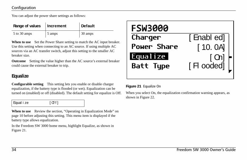
34 Freedom SW 3000 Owner’s Guide
Configuration
You can adjust the power share settings as follows:
When to use Set the Power Share setting to match the AC input breaker. Use this setting when connecting to an AC source. If using multiple AC sources via an AC transfer switch, adjust this setting to the smaller AC breaker size.Outcome Setting the value higher than the AC source’s external breaker could cause the external breaker to trip.
Equalize
Configurable setting This setting lets you enable or disable charger equalization, if the battery type is flooded (or wet). Equalization can be turned on (enabled) or off (disabled). The default setting for equalize is Off.
When to use Review the section, “Operating in Equalization Mode” on page 10 before adjusting this setting. This menu item is displayed if the battery type allows equalization.In the Freedom SW 3000 home menu, highlight Equalize, as shown in Figure 21.
When you select On, the equalization confirmation warning appears, as shown in Figure 22.
Range of values Increment Default
5 to 30 amps 5 amps 30 amps
Equalize [Off]
Figure 21 Equalize On
[Enabled][10.0A]
[On][Flooded]
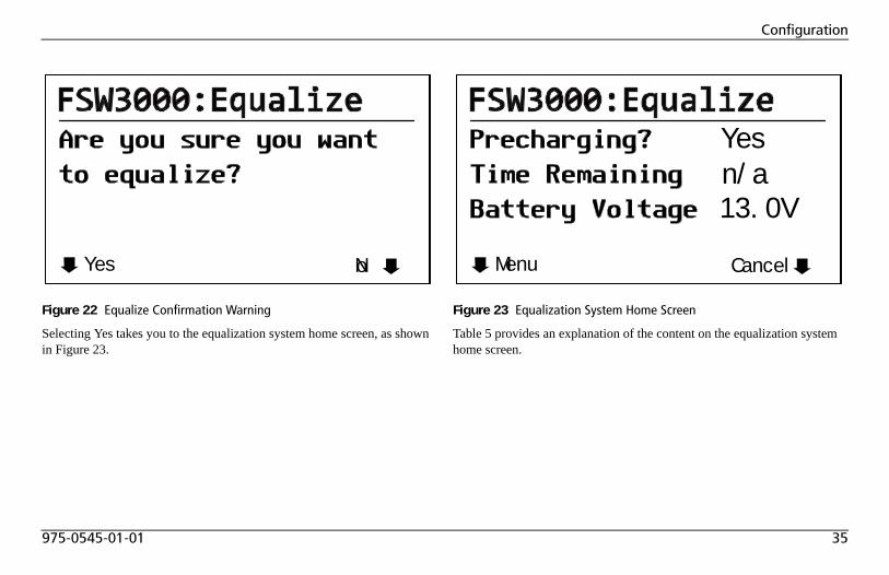
975-0545-01-01 35
Configuration
Selecting Yes takes you to the equalization system home screen, as shown in Figure 23.
Table 5 provides an explanation of the content on the equalization system home screen.
Figure 22 Equalize Confirmation Warning
Yes No
Figure 23 Equalization System Home Screen
Menu Cancel
Yesn/a13.0V
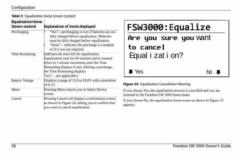
36 Freedom SW 3000 Owner’s Guide
Configuration
If you choose Yes, the equalization process is cancelled and you are returned to the Freedom SW 3000 home menu. If you choose No, the equalization home screen as shown in Figure 23 appears.
Table 5 Equalization Home Screen Content
Equalization Home Screen content Explanation of items displayedPrecharging • “Yes”—precharging occurs if batteries are not
fully charged before equalization. Batteries must be fully charged before equalization.
• “Done”—indicates the precharge is complete or if it was not required.
Time Remaining Indicates the time left for equalization. Equalization runs for 60 minutes and is counted down in 1 minute increments until the Time Remaining displays 0 min. (During a precharge, the Time Remaining displays “n/a”— not applicable.)
Battery Voltage Displays a range of 13.0 to 18.0V with a resolution of 0.1V.
Menu Pressing Menu returns you to Select Device screen.
Cancel Pressing Cancel will display a confirmation screen, as shown in Figure 24, asking you to confirm that you want to cancel equalization.
Figure 24 Equalization Cancellation Warning
Yes No
want
Equalization?
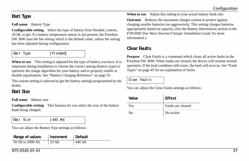
975-0545-01-01 37
Configuration
Batt Type
Full name Battery TypeConfigurable setting Select the type of battery from flooded, custom, AGM, or gel. If a battery temperature sensor is not present, the Freedom SW 3000 uses the hot setting which is the default value, unless the setting has been adjusted during configuration.
When to use This setting is adjusted for the type of battery you have. It is important during installation to choose the correct setting (battery type) to optimize the charge algorithm for your battery and to properly enable or disable equalization. See “Battery Charging Reference” on page 55.The custom setting is selected to get the battery settings programmed by the dealer.
Batt Size
Full name Battery sizeConfigurable setting This features let you select the size of the battery bank being charged.
You can adjust the Battery Size settings as follows:
When to use Adjust this setting to your actual battery bank size. Outcome Reduces the maximum charger current to protect against charging smaller batteries too aggressively. This setting charges batteries appropriately based on capacity. (See the Battery Information section in the FSW3000 Sine Wave Inverter/Charger Installation Guide for more information.)
Clear Faults
Purpose Clear Faults is a command which clears all active faults in the Freedom SW 3000. When faults are cleared, the device will resume normal operation. If the fault condition still exists, the fault will reoccur. See “Fault Types” on page 45 for an explanation of faults.
You can adjust the Clear Faults settings as follows:
Batt Type [Flooded]
Batt Size [440 Ah]
Range of values Increment Default50 Ah to 2000 Ah 10 Ah 440 Ah
Clear Faults
Value Effect
Yes Faults are cleared
No No action
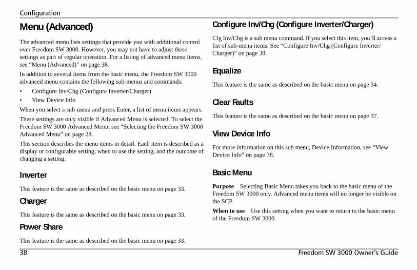
38 Freedom SW 3000 Owner’s Guide
Configuration
Menu (Advanced)The advanced menu lists settings that provide you with additional control over Freedom SW 3000. However, you may not have to adjust these settings as part of regular operation. For a listing of advanced menu items, see “Menu (Advanced)” on page 38. In addition to several items from the basic menu, the Freedom SW 3000 advanced menu contains the following sub-menus and commands:• Configure Inv/Chg (Configure Inverter/Charger)• View Device InfoWhen you select a sub-menu and press Enter, a list of menu items appears.These settings are only visible if Advanced Menu is selected. To select the Freedom SW 3000 Advanced Menu, see “Selecting the Freedom SW 3000 Advanced Menu” on page 28.This section describes the menu items in detail. Each item is described as a display or configurable setting, when to use the setting, and the outcome of changing a setting.
Inverter
This feature is the same as described on the basic menu on page 33.
Charger
This feature is the same as described on the basic menu on page 33.
Power Share
This feature is the same as described on the basic menu on page 33.
Configure Inv/Chg (Configure Inverter/Charger)
Cfg Inv/Chg is a sub menu command. If you select this item, you’ll access a list of sub-menu items. See “Configure Inv/Chg (Configure Inverter/Charger)” on page 38.
Equalize
This feature is the same as described on the basic menu on page 34.
Clear Faults
This feature is the same as described on the basic menu on page 37.
View Device Info
For more information on this sub menu, Device Information, see “View Device Info” on page 38.
Basic Menu
Purpose Selecting Basic Menu takes you back to the basic menu of the Freedom SW 3000 only. Advanced menu items will no longer be visible on the SCP.When to use Use this setting when you want to return to the basic menu of the Freedom SW 3000.
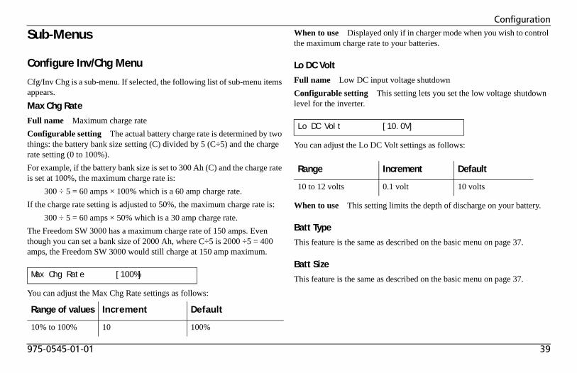
975-0545-01-01 39
Configuration
Sub-Menus
Configure Inv/Chg Menu
Cfg/Inv Chg is a sub-menu. If selected, the following list of sub-menu items appears.Max Chg Rate
Full name Maximum charge rateConfigurable setting The actual battery charge rate is determined by two things: the battery bank size setting (C) divided by 5 (C÷5) and the charge rate setting (0 to 100%).For example, if the battery bank size is set to 300 Ah (C) and the charge rate is set at 100%, the maximum charge rate is:
300 ÷ 5 = 60 amps × 100% which is a 60 amp charge rate.If the charge rate setting is adjusted to 50%, the maximum charge rate is:
300 ÷ 5 = 60 amps × 50% which is a 30 amp charge rate.The Freedom SW 3000 has a maximum charge rate of 150 amps. Even though you can set a bank size of 2000 Ah, where C÷5 is 2000 ÷5 = 400 amps, the Freedom SW 3000 would still charge at 150 amp maximum.
You can adjust the Max Chg Rate settings as follows:
When to use Displayed only if in charger mode when you wish to control the maximum charge rate to your batteries.
Lo DC Volt
Full name Low DC input voltage shutdownConfigurable setting This setting lets you set the low voltage shutdown level for the inverter.
You can adjust the Lo DC Volt settings as follows:
When to use This setting limits the depth of discharge on your battery.
Batt Type
This feature is the same as described on the basic menu on page 37.
Batt Size
This feature is the same as described on the basic menu on page 37.Max Chg Rate [100%]
Range of values Increment Default
10% to 100% 10 100%
Lo DC Volt [10.0V]
Range Increment Default
10 to 12 volts 0.1 volt 10 volts
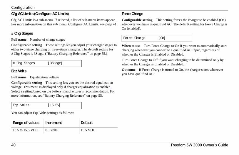
40 Freedom SW 3000 Owner’s Guide
Configuration
Cfg AC Limits (Configure AC Limits)
Cfg AC Limits is a sub-menu. If selected, a list of sub-menu items appear. For more information on this sub menu, Configure AC Limits, see page 41.
# Chg Stages
Full name Number of charge stagesConfigurable setting These settings let you adjust your charger stages to either two-stage charging or three-stage charging. The default setting for # Chg Stages is 3Stage. (“Battery Charging Reference” on page 55.)
Eqz Volts
Full name Equalization voltageConfigurable setting This setting lets you set the desired equalization voltage. This menu is displayed only if charger equalization is enabled. Select a setting based on the battery manufacturer’s recommendation. For more information, see “Battery Charging Reference” on page 55.
You can adjust Eqz Volts settings as follows:
Force Charge
Configurable setting This setting forces the charger to be enabled (On) whenever you have re qualified AC. The default setting for Force Charge is On (enabled).
When to use Turn Force Charge to On if you want to automatically start charging whenever you connect to a qualified AC input, regardless of whether the Charger is Enabled or Disabled.Turn Force Charge to Off if you want charging to be determined only by whether the Charger is Enabled or Disabled.Outcome If Force Charge is turned to On, the charger starts whenever you have qualified AC.
# Chg Stages [3Stage]
Eqz Volts [15.5V]
Range of values Increment Default
13.5 to 15.5 VDC 0.1 volts 15.5 VDC
Force Charge [On]
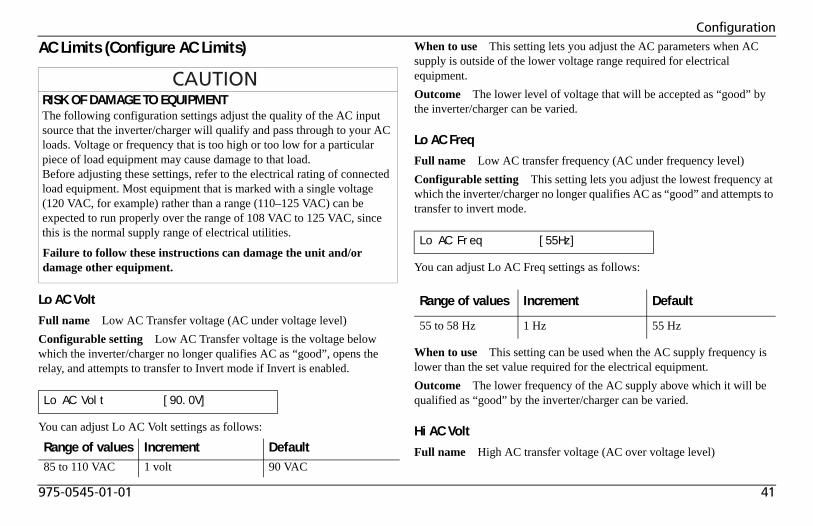
975-0545-01-01 41
Configuration
AC Limits (Configure AC Limits)
Lo AC Volt
Full name Low AC Transfer voltage (AC under voltage level)Configurable setting Low AC Transfer voltage is the voltage below which the inverter/charger no longer qualifies AC as “good”, opens the relay, and attempts to transfer to Invert mode if Invert is enabled.
You can adjust Lo AC Volt settings as follows:
When to use This setting lets you adjust the AC parameters when AC supply is outside of the lower voltage range required for electrical equipment.Outcome The lower level of voltage that will be accepted as “good” by the inverter/charger can be varied.
Lo AC Freq
Full name Low AC transfer frequency (AC under frequency level)Configurable setting This setting lets you adjust the lowest frequency at which the inverter/charger no longer qualifies AC as “good” and attempts to transfer to invert mode.
You can adjust Lo AC Freq settings as follows:
When to use This setting can be used when the AC supply frequency is lower than the set value required for the electrical equipment.Outcome The lower frequency of the AC supply above which it will be qualified as “good” by the inverter/charger can be varied.
Hi AC Volt
Full name High AC transfer voltage (AC over voltage level)
RISK OF DAMAGE TO EQUIPMENTThe following configuration settings adjust the quality of the AC input source that the inverter/charger will qualify and pass through to your AC loads. Voltage or frequency that is too high or too low for a particular piece of load equipment may cause damage to that load. Before adjusting these settings, refer to the electrical rating of connected load equipment. Most equipment that is marked with a single voltage (120 VAC, for example) rather than a range (110–125 VAC) can be expected to run properly over the range of 108 VAC to 125 VAC, since this is the normal supply range of electrical utilities.
Failure to follow these instructions can damage the unit and/or damage other equipment.
Lo AC Volt [90.0V]
Range of values Increment Default85 to 110 VAC 1 volt 90 VAC
Lo AC Freq [55Hz]
Range of values Increment Default
55 to 58 Hz 1 Hz 55 Hz
42 Freedom SW 3000 Owner’s Guide
Configuration
Configurable setting This setting lets you adjust the voltage above which the inverter/charger no longer qualifies AC as “good” and transfers to Invert.
You can adjust Hi AC Volt settings as follows:
When to use This setting lets you adjust the AC parameters when AC supply is outside the upper voltage range required for electrical equipment.Outcome The upper limit of the voltage that will be qualified as “good” by the inverter/charger can be varied.
Hi AC Freq
Full name High AC transfer frequency (AC over frequency level)Configurable setting This setting lets you adjust the highest frequency at which the Freedom SW 3000 no longer qualifies AC as “good” and transfers to Invert.
You can adjust Hi AC Freq settings as follows:
When to use This setting lets you adjust the AC parameters when the AC supply is outside the higher frequency range required for electrical equipment.Outcome The highest frequency of the AC supply that will be qualified as “good” by the inverter/charger can be varied.
Hi AC Volt [135V]
Range of values Increment Default
120 to 145 VAC 1 volt 135 VAC
Hi AC Freq [65Hz]
Range of values Increment Default
62 to 70 Hz 1 Hz 65 Hz
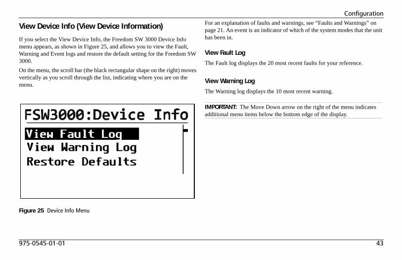
975-0545-01-01 43
Configuration
View Device Info (View Device Information)
If you select the View Device Info, the Freedom SW 3000 Device Info menu appears, as shown in Figure 25, and allows you to view the Fault, Warning and Event logs and restore the default setting for the Freedom SW 3000. On the menu, the scroll bar (the black rectangular shape on the right) moves vertically as you scroll through the list, indicating where you are on the menu.
For an explanation of faults and warnings, see “Faults and Warnings” on page 21. An event is an indicator of which of the system modes that the unit has been in.
View Fault Log
The Fault log displays the 20 most recent faults for your reference.
View Warning Log
The Warning log displays the 10 most recent warning.
Figure 25 Device Info Menu
IMPORTANT: The Move Down arrow on the right of the menu indicates additional menu items below the bottom edge of the display.
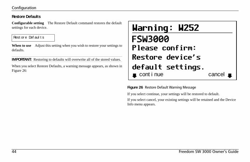
44 Freedom SW 3000 Owner’s Guide
Configuration
Restore Defaults
Configurable setting The Restore Default command restores the default settings for each device.
When to use Adjust this setting when you wish to restore your settings to defaults.
When you select Restore Defaults, a warning message appears, as shown in Figure 26:
If you select continue, your settings will be restored to default. If you select cancel, your existing settings will be retained and the Device Info menu appears.
Restore Defaults
IMPORTANT: Restoring to defaults will overwrite all of the stored values.
Figure 26 Restore Default Warning Message
continue cancel
975-0545-01-01 45
Troubleshooting
IntroductionThe Freedom SW 3000 is designed for high reliability of operation and has a number of protection features to provide trouble free operation. If, however, you have any problems operating your inverter/charger read this troubleshooting chapter.If you cannot resolve the problem, record the necessary information on the form, “Information About Your System” on page 4. This information will help your dealer or Xantrex Customer Service to assist you better when you contact them.
When a fault or warning message appears, you can acknowledge the message to clear the screen. To acknowledge a fault or warning message, press the Enter button on the SCP. This action does not clear the fault or
warning condition, so you should consult Table 8 and Table 9 for suggested actions after you have acknowledged the message. Refer to the System Control Panel Owner’s Guide for more information on faults and warnings.
Fault Types
There are three types of fault messages: automatic faults, manual faults, and escalating automatic faults. Table 6 describes how they differ in their behavior and how you can respond to them when they appear on the SCP.
ELECTRICAL SHOCK HAZARDDo not disassemble the inverter/charger. The Freedom SW 3000 contains no user-serviceable parts.
Failure to follow these instructions will result in death or serious injury.
Table 6 Faults Types and Behaviors
Fault type BehaviorAutomatic faults Clear automatically if the fault condition that
generated the message goes away. You can also acknowledge automatic faults without waiting for them to clear automatically.
Manual faults Require you to clear them by:• selecting Clear Faults on the Freedom SW
3000 or on the device that generated the fault (if the fault condition still exists, the fault message reappears)
• correcting the condition that caused the fault
46 Freedom SW 3000 Owner’s Guide
Troubleshooting
Warning Types
There are two types of warnings: automatic and manual. When the Freedom SW 3000 detects a warning condition, it displays a warning message on the SCP.Table 7 describes how they differ in their behavior and in how you can respond to them when they appear on the SCP.
Escalating automatic faults
Clear automatically if the fault condition goes away, just like an automatic fault. However, if an escalating automatic fault occurs several times within a defined time period, the escalating automatic fault becomes a manual fault, requiring user intervention. For example, if three faults occur in one minute, it will no longer clear itself but becomes a manual fault. Then you must identify the problem, correct the fault condition, and clear the fault or reset the device.
Table 6 Faults Types and Behaviors
Fault type Behavior
Table 7 Warning Types and Behavior
Warning type BehaviorAutomatic warning Clear automatically if the fault condition that
generated the message goes away. You can also acknowledge automatic warnings without waiting for them to clear automatically.
Manual warning Require you to acknowledge them before you can proceed with configuring or operating the Freedom SW 3000. Manual warnings are usually in the form of a Yes/No question that you may acknowledge by pressing the Enter button on the SCP for Yes and the Exit button for No.Refer to the System Control Panel Owner’s Guide for more information.
975-0545-01-01 47
Troubleshooting
Troubleshooting ReferenceThis chapter provides you with troubleshooting tips to identify and solve most problems that can occur with the Freedom SW 3000.This chapter is divided into the following four sections:
General Troubleshooting Guidelines
This section will help you narrow down the source of any problem you may encounter. Please read the following troubleshooting steps:1. Check for a Warning or Fault message on the SCP. See “Warning
Messages” on page 49 and “Fault Messages” on page 50 for descriptions of these messages and the specific actions to take. If a message is displayed, record it before doing anything further.
2. As soon as possible, record on the form, “Information About Your System” on page 69, the conditions at the time the problem occurred. These details should include the following as well as any other information asked for on page page 4:• Loads the Freedom SW 3000 was running or attempting to run• Battery condition at the time of failure (voltage, state of charge,
for example), if known• Recent sequence of events (for example, charging had just
finished, we disconnected shore power as were preparing to leave the RV park, but the inverter didn’t come on)
• Any known unusual AC input factors such as low voltage or unstable generator output
• Extreme conditions which may have existed at the time (temperature, vibrations, moisture, for example).
3. Attempt the solution indicated in Table 8 or Table 9.
Section Page Number
General Troubleshooting Guidelines
See page 47.
Warning Messages See page 49.
Fault Messages See page 50.
Inverter Applications (Loads) See page 54.
48 Freedom SW 3000 Owner’s Guide
Troubleshooting
4. If your Freedom SW 3000 or SCP is not displaying a Fault light, check the following list to make sure that the present state of the installation allows proper operation of the unit:
❐ Is the inverter/charger located in a clean, dry, adequately ventilated place?
❐ Have the AC input breakers opened? If so, your pass through load may have exceeded the rating of one or more of the input breakers.
❐ Are the battery cables adequately sized and short enough?
❐ Is the battery in good condition and are all DC connections tight?
❐ Are the AC input and output connections and wiring in good condition?
❐ Are the configuration settings correct for your particular installation?
❐ Are the display panel and the communications cable properly connected and undamaged?
❐ Is the battery temperature sensor and its cable properly connected and undamaged?
5. Contact Xantrex Customer Service for further assistance. Please be prepared to describe details of your system installation and provide the model and serial number of the unit. See “Contact Information” on page v for contact information.
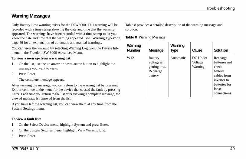
975-0545-01-01 49
Troubleshooting
Warning Messages
Only Battery Low warning exists for the FSW3000. This warning will be recorded with a time stamp showing the date and time that the warning appeared. The warnings have been recorded with a time stamp to let you know the date and time that the warning appeared. See “Warning Types” on page 46 for an explanation of automatic and manual warnings.You can view the warning by selecting Warning Log from the Device Info menu in the Freedom SW 3000 Advanced Menu.To view a message from a warning list:1. On the list, use the up arrow or down arrow button to highlight the
message you want to view.2. Press Enter.
The complete message appears.After viewing the message, you can return to the warning list by pressing Exit or continue to the menu for the device that caused the fault by pressing Enter. Each time you return to the list after viewing a complete message, the viewed message is removed from the list.If you have left the warning list, you can view them at any time from the System Settings menu.
To view a fault list:1. On the Select Device menu, highlight System and press Enter.2. On the System Settings menu, highlight View Warning List.3. Press Enter.
Table 8 provides a detailed description of the warning message and solution.
Table 8 Warning Message
Warning Number Message
Warning Type Cause Solution
W12 Battery voltage is getting low. Recharge battery.
Automatic DC Under Voltage Warning
Recharge batteries and check battery cables from inverter to batteries for loose connections.
50 Freedom SW 3000 Owner’s Guide
Troubleshooting
Fault Messages
When the Freedom SW 3000 detects a fault condition, the fault is displayed on the SCP and also is indicated by the illuminated red Fault light on the Freedom SW 3000 front panel. A fault affects the operation of the unit. See “Fault Types” on page 45 for an explanation of the different fault types.You can view the 20 most recent fault messages of the Freedom SW 3000 by selecting Fault Log from the Device Info menu in the Freedom SW 3000 Advanced Menu.If several faults occur before you can acknowledge or clear them, they are displayed together on a warning list. This list contains messages from every Xanbus-enabled device, not just the Freedom SW 3000. You can select a message and view its details from the fault list.To view a message from a fault list:1. On the list, use the up arrow or down arrow button to highlight the
message you want to view.2. Press Enter.
The complete message appears.After viewing the message, you can return to the fault list by pressing Exit or continue to the menu for the device that caused the fault by pressing Enter. Each time you return to the list after viewing a complete message, the viewed message is removed from the list.If you have left the fault list, you can view them at any time from the System Settings menu.
To view a fault list:1. On the Select Device menu, highlight System and press Enter.2. On the System Settings menu, highlight View Fault List.3. Press Enter.
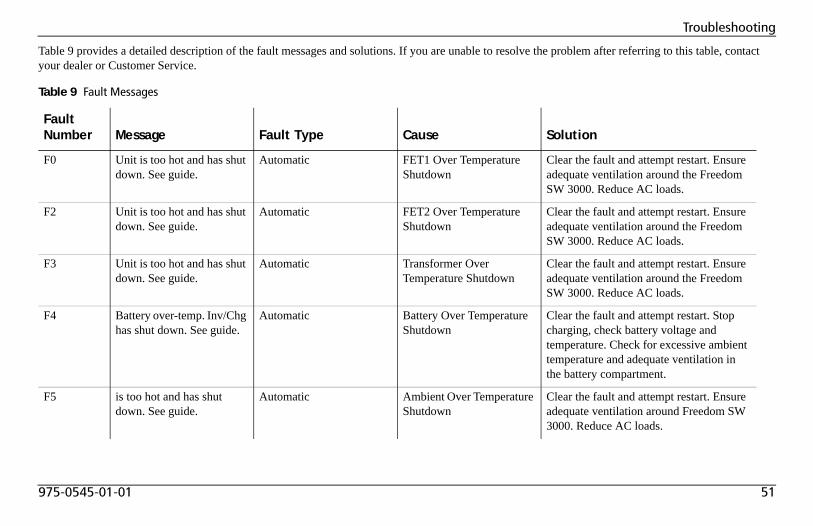
975-0545-01-01 51
Troubleshooting
Table 9 provides a detailed description of the fault messages and solutions. If you are unable to resolve the problem after referring to this table, contact your dealer or Customer Service.
Table 9 Fault Messages
Fault Number Message Fault Type Cause Solution
F0 Unit is too hot and has shut down. See guide.
Automatic FET1 Over Temperature Shutdown
Clear the fault and attempt restart. Ensure adequate ventilation around the Freedom SW 3000. Reduce AC loads.
F2 Unit is too hot and has shut down. See guide.
Automatic FET2 Over Temperature Shutdown
Clear the fault and attempt restart. Ensure adequate ventilation around the Freedom SW 3000. Reduce AC loads.
F3 Unit is too hot and has shut down. See guide.
Automatic Transformer Over Temperature Shutdown
Clear the fault and attempt restart. Ensure adequate ventilation around the Freedom SW 3000. Reduce AC loads.
F4 Battery over-temp. Inv/Chg has shut down. See guide.
Automatic Battery Over Temperature Shutdown
Clear the fault and attempt restart. Stop charging, check battery voltage and temperature. Check for excessive ambient temperature and adequate ventilation in the battery compartment.
F5 is too hot and has shut down. See guide.
Automatic Ambient Over Temperature Shutdown
Clear the fault and attempt restart. Ensure adequate ventilation around Freedom SW 3000. Reduce AC loads.
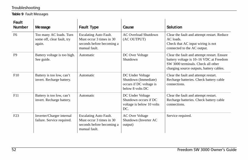
52 Freedom SW 3000 Owner’s Guide
Troubleshooting
F6 Too many AC loads. Turn some off, clear fault, try again.
Escalating Auto Fault. Must occur 3 times in 30 seconds before becoming a manual fault.
AC Overload Shutdown (AC OUTPUT)
Clear the fault and attempt restart. Reduce AC loads.Check that AC input wiring is not connected to the AC output.
F9 Battery voltage is too high. See guide.
Automatic DC Over Voltage Shutdown
Clear the fault and attempt restart. Ensure battery voltage is 10–16 VDC at Freedom SW 3000 terminals. Check all other charging source outputs, battery cables.
F10 Battery is too low, can’t invert. Recharge battery.
Automatic DC Under Voltage Shutdown (Immediate) occurs if DC voltage is below 8 volts DC
Clear the fault and attempt restart. Recharge batteries. Check battery cable connections.
F11 Battery is too low, can’t invert. Recharge battery.
Automatic DC Under Voltage Shutdown occurs if DC voltage is below 10 volts DC.
Clear the fault and attempt restart. Recharge batteries. Check battery cable connections.
F23 Inverter/Charger internal failure. Service required.
Escalating Auto Fault. Must occur 3 times in 30 seconds before becoming a manual fault.
AC Over Voltage Shutdown (Inverter AC output)
Service required.
Table 9 Fault Messages
Fault Number Message Fault Type Cause Solution
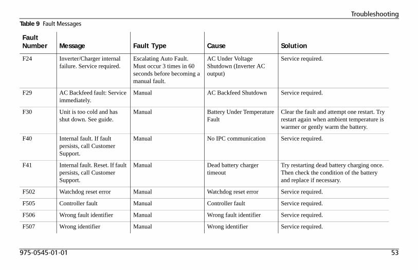
975-0545-01-01 53
Troubleshooting
F24 Inverter/Charger internal failure. Service required.
Escalating Auto Fault. Must occur 3 times in 60 seconds before becoming a manual fault.
AC Under Voltage Shutdown (Inverter AC output)
Service required.
F29 AC Backfeed fault: Service immediately.
Manual AC Backfeed Shutdown Service required.
F30 Unit is too cold and has shut down. See guide.
Manual Battery Under Temperature Fault
Clear the fault and attempt one restart. Try restart again when ambient temperature is warmer or gently warm the battery.
F40 Internal fault. If fault persists, call Customer Support.
Manual No IPC communication Service required.
F41 Internal fault. Reset. If fault persists, call Customer Support.
Manual Dead battery charger timeout
Try restarting dead battery charging once. Then check the condition of the battery and replace if necessary.
F502 Watchdog reset error Manual Watchdog reset error Service required.
F505 Controller fault Manual Controller fault Service required.
F506 Wrong fault identifier Manual Wrong fault identifier Service required.
F507 Wrong identifier Manual Wrong identifier Service required.
Table 9 Fault Messages
Fault Number Message Fault Type Cause Solution
54 Freedom SW 3000 Owner’s Guide
Troubleshooting
Inverter Applications
The Freedom SW 3000 performs differently depending on the AC loads connected to it. If you are having problems with any of your loads, read this section.
Resistive Loads
These are the loads that the inverter finds the simplest and most efficient to drive. Voltage and current are in phase, which means they are in step with one another. Resistive loads usually generate heat in order to accomplish their tasks. Toasters, coffee pots, and incandescent lights are typical resistive loads. It is usually impractical to run larger resistive loads—such as electric stove and water heaters—from an inverter due to their high current requirements. Even though the inverter may be able to accommodate the load, the size of battery bank required would be impractical if the load is to be run for long periods.
Motor Loads
Induction motors (motors without brushes) require two to six times their running current on start up. The most demanding are those that start under load (for example, compressors and pumps). Of the capacitor start motors (typical in drill presses, band saws for example), the largest you can expect to run is 1 hp. Universal motors are generally easier to start. Since motor characteristics vary, only testing will determine whether a specific load can be started and how long it can be run.
If a motor fails to start within a few seconds or loses power after running for a time, it should be turned off. When the inverter attempts to start a load that is greater than it can handle, the inverter will turn itself off after a few seconds.
975-0545-01-01 55
Battery Charging ReferenceThis section describes the multistage charging algorithm (formula) of the Freedom SW 3000.
Battery TypesFreedom SW 3000 charges flooded (or wet) lead-acid, gel, AGM (absorbed glass mat), and custom batteries. See “Batt Type” on page 16 for information on selecting your battery type.Flooded (or wet) batteries have removable battery caps for refilling with distilled water and testing the electrolyte.Gel batteries have the electrolyte in the form of a gel rather than a liquid and do not require topping up. Gel batteries are sealed and the battery caps are not removable. AGM (Absorbed Glass Mat) batteries are similar to gel batteries except that the electrolyte is absorbed into a fiberglass matting.Custom Custom is configured by the dealer, factory, or service center for battery types other than those listed above.
RISK OF BATTERY DAMAGESince the Freedom SW 3000 can only select one battery type setting for all batteries connected to its bank, do not mix battery types. All connected batteries should either be: Flooded (or wet) or Gel or AGM or Custom.
Failure to follow these instructions can damage the unit and/or damage other equipment.
56 Freedom SW 3000 Owner’s Guide
Battery Charging Reference
Charge Algorithm Stages
Three-Stage charging
If three-stage charging is enabled, the Freedom SW 3000 will charge batteries in a sequence known as three-stage charging. The charging voltage delivered to the battery depends on the battery:• type setting• temperature (by switch setting or battery temperature sensor)• state of chargeThe three automatic stages are:• bulk• absorption• floatSee Figure 27 for a graph of the three-stage charging profile.There is a fourth stage, equalization, which is initialized manually as it is only performed occasionally and only on flooded (or wet) batteries.Bulk Charge In the first stage—the bulk charge—Freedom SW 3000 delivers its full-rated output current. This constant current is delivered to the batteries until the battery voltage approaches its gassing voltage—typically around 13.5 volts for 12 volt batteries. The bulk charge stage restores about 75% of the battery’s charge.The exit from bulk stage to the next stage, absorption, occurs under the following condition:• battery voltage is more than the gassing voltage (VG) for a specified
amount of time (3 minute default).
With an AC reconnect to qualified AC from the utility power or a generator during the bulk stage, the unit will return to the bulk stage.Absorption Charge During the first part of absorption charge, the Freedom SW 3000 delivers its full rated output current until the absorption voltage is reached. At this point, the Freedom SW 3000 will transition to a constant voltage mode by keeping the charge voltage constant at the absorption voltage level, and the battery gradually reduces the charging current it demands as the battery attains full charge.The absorption stage has the following exit criteria:• Overall time in absorption timeout (ΔTA) has a default of 6 hours.• Time in constant voltage absorption timeout (ΔTCV) has a default of 1
hour.• Charge current level drops below a specified limit (IH) for a specified
amount of time, which has a default of 2% of C in Ah for 3 minutes.See “Charge Algorithm Definitions” on page 58 for more information.With an AC reconnect during the absorption stage, the unit will transition to the float stage for three-stage charging and no-float stage for two-stage charging.Float Charge In the third stage—the float charge—which is a maintenance mode, the output voltage of the charger is reduced to a lower level, typically about 13.5 (VF1) volts to maintain the battery’s charge without losing electrolyte through gassing.With AC reconnected during this stage, the unit will return to the float stage.
975-0545-01-01 57
Battery Charging Reference
Equalization Charge The equalization charge must be manually initiated from the SCP because it is not required each time the battery is recharged. Equalization is a deliberate overcharge designed to return each cell to optimum condition by reducing sulfation and stratification in the battery. The overcharge helps the battery to reach and maintain peak capacity.An equalization charge should be performed only on flooded, vented (non-sealed or “wet”) batteries. It should be performed only if recommended by the battery manufacturer and only as often as specified.After initiating an equalize charge cycle, the charger will always execute a bulk and absorption charge stage before starting the actual equalize charge stage. The equalize charge stage has a default current and voltage setpoint at 10% of C in Ah and 15.5 Vdc, respectively. During the equalize charge stage, the charger will produce current equal to the current setpoint as long as the battery voltage is still less than the voltage setpoint. When the voltage setpoint is reached, the charger will change its current output to keep the battery voltage steady at the voltage setpoint level.There is a timeout (default is 1 hour) for the equalize charge stage. The charger will exit equalize after the timeout has occurred, even if the voltage setpoint has not been reached. Should another equalize cycle be required, it has to be manually initiated from the SCP.Should an AC reconnect occur during the equalize charge stage, the charger will return to the float/no-float charge stage, depending on which one is selected.
Two-Stage Charging
If the two-stage charge is enabled, the charger finishes the absorption charge but does not go to float mode because some battery manufacturers advise against floating their batteries. The Freedom SW 3000 goes into a monitoring mode instead where the charger monitors the batteries but does not float them. A new two-stage charge cycle will be initiated under the same conditions as for three-stage charging.
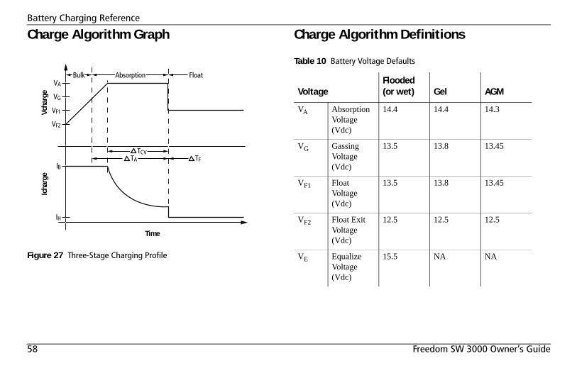
58 Freedom SW 3000 Owner’s Guide
Battery Charging Reference
Charge Algorithm Graph Charge Algorithm Definitions
Figure 27 Three-Stage Charging Profile
IH
IB
VF2
VF1
VG
VA
Float
Icha
rge
Vcha
rge
Time
TCVTA TF
Bulk Absorption
Table 10 Battery Voltage Defaults
VoltageFlooded (or wet) Gel AGM
VA Absorption Voltage (Vdc)
14.4 14.4 14.3
VG Gassing Voltage (Vdc)
13.5 13.8 13.45
VF1 Float Voltage (Vdc)
13.5 13.8 13.45
VF2 Float Exit Voltage (Vdc)
12.5 12.5 12.5
VE Equalize Voltage (Vdc)
15.5 NA NA
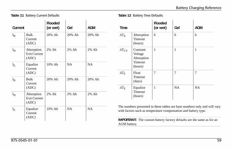
975-0545-01-01 59
Battery Charging Reference
The numbers presented in these tables are base numbers only and will vary with factors such as temperature compensation and battery type.
Table 11 Battery Current Defaults
CurrentFlooded (or wet) Gel AGM
IB Bulk Current (ADC)
20% Ah 20% Ah 20% Ah
IH Absorption Exit Current (ADC)
2% Ah 2% Ah 2% Ah
IE Equalize Current (ADC)
10% Ah NA NA
IB Bulk Current (ADC)
20% Ah 20% Ah 20% Ah
IH Absorption Exit Current (ADC)
2% Ah 2% Ah 2% Ah
IE Equalize Current (ADC)
10% Ah NA NA
Table 12 Battery Time Defaults
TimeFlooded (or wet) Gel AGM
ΔTA Absorption Timeout (hours)
6 6 6
ΔTCV Constant Voltage Absorption Timeout (hours)
1 1 1
ΔTF Float Timeout (days)
7 7 7
ΔTE Equalize Timeout (hours)
1 NA NA
IMPORTANT: The custom battery factory defaults are the same as for an AGM battery.
60 Freedom SW 3000 Owner’s Guide
Battery Charging Reference
Battery Charger InterruptionIf battery charging is interrupted in bulk charge (for example, AC is disconnected, or a fault occurs), the unit will return to bulk charge when battery charging resumes.If battery charging is interrupted in any stage other than bulk, the unit will go to float charge when battery charging resumes.However, a new bulk charge cycle is initiated when battery charging begins, if:• the battery drops below 12.5 Vdc for 15 minutes (VF2) i.e., the
15-minute countdown is independent of mode: for example, inverting, bulk charging, or float charging, and
• 7 days have passed from the time the charger completed Absorption (ΔTF).
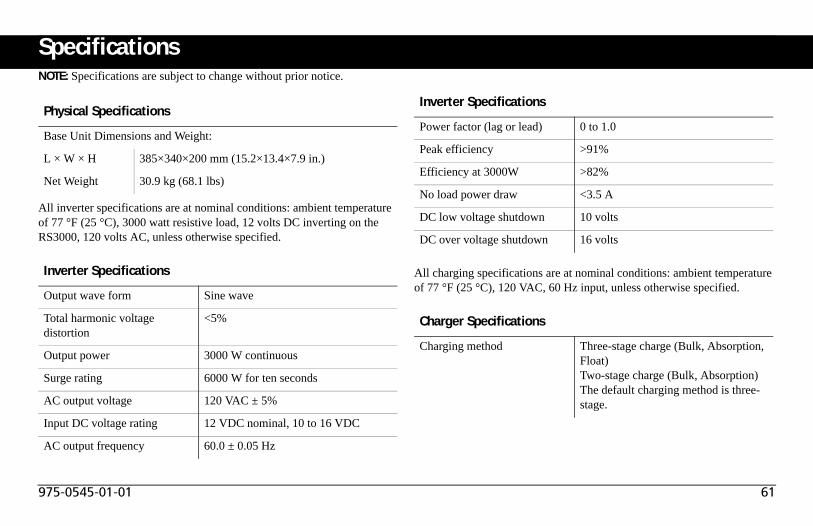
975-0545-01-01 61
SpecificationsNOTE: Specifications are subject to change without prior notice.
All inverter specifications are at nominal conditions: ambient temperature of 77 °F (25 °C), 3000 watt resistive load, 12 volts DC inverting on the RS3000, 120 volts AC, unless otherwise specified.
All charging specifications are at nominal conditions: ambient temperature of 77 °F (25 °C), 120 VAC, 60 Hz input, unless otherwise specified.
Physical Specifications
Base Unit Dimensions and Weight:
L × W × H 385×340×200 mm (15.2×13.4×7.9 in.)
Net Weight 30.9 kg (68.1 lbs)
Inverter Specifications
Output wave form Sine wave
Total harmonic voltage distortion
<5%
Output power 3000 W continuous
Surge rating 6000 W for ten seconds
AC output voltage 120 VAC ± 5%
Input DC voltage rating 12 VDC nominal, 10 to 16 VDC
AC output frequency 60.0 ± 0.05 Hz
Power factor (lag or lead) 0 to 1.0
Peak efficiency >91%
Efficiency at 3000W >82%
No load power draw <3.5 A
DC low voltage shutdown 10 volts
DC over voltage shutdown 16 volts
Charger Specifications
Charging method Three-stage charge (Bulk, Absorption, Float)Two-stage charge (Bulk, Absorption)The default charging method is three-stage.
Inverter Specifications
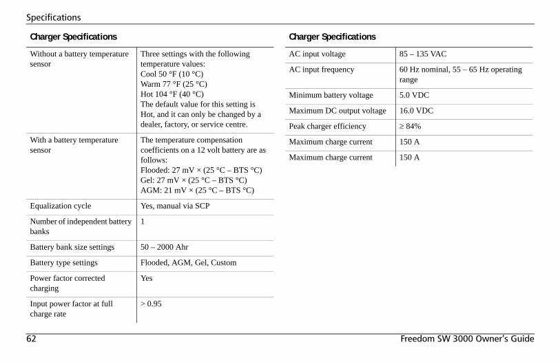
62 Freedom SW 3000 Owner’s Guide
Specifications
Without a battery temperature sensor
Three settings with the following temperature values:Cool 50 °F (10 °C)Warm 77 °F (25 °C)Hot 104 °F (40 °C)The default value for this setting is Hot, and it can only be changed by a dealer, factory, or service centre.
With a battery temperature sensor
The temperature compensation coefficients on a 12 volt battery are as follows:Flooded: 27 mV × (25 °C – BTS °C)Gel: 27 mV × (25 °C – BTS °C)AGM: 21 mV × (25 °C – BTS °C)
Equalization cycle Yes, manual via SCP
Number of independent battery banks
1
Battery bank size settings 50 – 2000 Ahr
Battery type settings Flooded, AGM, Gel, Custom
Power factor corrected charging
Yes
Input power factor at full charge rate
> 0.95
Charger Specifications
AC input voltage 85 – 135 VAC
AC input frequency 60 Hz nominal, 55 – 65 Hz operating range
Minimum battery voltage 5.0 VDC
Maximum DC output voltage 16.0 VDC
Peak charger efficiency ≥ 84%
Maximum charge current 150 A
Maximum charge current 150 A
Charger Specifications
975-0545-01-01 63
Specifications
All transfer specifications are at nominal conditions: ambient temperature of 77 °F (25 °C), 120 VAC, 60 Hz input, unless otherwise specified.
Fan Operation
The internal cooling fans are automatic and temperature-controlled.NOTE: This internal temperature of the inverter/charger may be caused by heat in the inverter/charger or by high ambient temperature.
Transfer and General Specifications
Transfer time—utility to invert 20 ms
Minimum AC input voltage for transfer
85 VAC RMS
Maximum AC input voltage for transfer
135 VAC RMS
Minimum AC input frequency for transfer
55 Hz
Maximum AC input frequency for transfer
65 Hz
Cooling Fan-cooled, temperature controlled.
Supported AC input types Split phase (up to 30 amps per line)Dual input (up to 30 amps per line)
Environmental Specifications
Nominal Ambient temperature 77 °F (25 °C)
Maximum Operating Temperature
140 °F (60 °C) See “Invert Power Derating versus Ambient Temperature” on page 64.
Storage temperature range –40 ° to 185 °F (–40 to 85 °C)
Humidity: Operation/Storage ≤ 95% RH, non-condensing
Regulatory Approvals
Safety CSA C22.2 No. 107.1UL 458
EMC FCC Part 15B Class BIndustry Canada ICES-0003 Class B
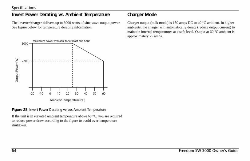
64 Freedom SW 3000 Owner’s Guide
Specifications
Invert Power Derating vs. Ambient Temperature
The inverter/charger delivers up to 3000 watts of sine wave output power. See figure below for temperature derating information.
If the unit is in elevated ambient temperature above 60 °C, you are required to reduce power draw according to the figure to avoid over-temperature shutdown.
Charger Mode
Charger output (bulk mode) is 150 amps DC to 40 °C ambient. In higher ambients, the charger will automatically derate (reduce output current) to maintain internal temperatures at a safe level. Output at 60 °C ambient is approximately 75 amps.
Figure 28 Invert Power Derating versus Ambient Temperature
2200
3000Maximum power available for at least one hour
Out
putP
ower
(W)
Ambient Temperature (°C)
-20 -10 0 10 20 30 40 50 60
975-0545-01-01 65
Warranty and Return Information
WarrantyWhat does this warranty cover and how long does it last? This Limited Warranty is provided by Xantrex Technology Inc. (“Xantrex”) and covers defects in workmanship and materials in your Freedom SW 3000 Inverter/Charger. This warranty period lasts for 24 months from the date of purchase at the point of sale to you, the original end user customer, unless otherwise agreed in writing (the “Warranty Period”). You will be required to demonstrate proof of purchase to make warranty claims.This Limited Warranty is transferable to subsequent owners but only for the unexpired portion of the Warranty Period. Subsequent owners also require original proof of purchase as described in “What proof of purchase is required?”What will Xantrex do? During the Warranty Period Xantrex will, at its option, repair the product (if economically feasible) or replace the defective product free of charge, provided that you notify Xantrex of the product defect within the Warranty Period, and provided that Xantrex through inspection establishes the existence of such a defect and that it is covered by this Limited Warranty. Xantrex will, at its option, use new and/or reconditioned parts in performing warranty repair and building replacement products. Xantrex reserves the right to use parts or products of original or improved design in the repair or replacement. If Xantrex repairs or replaces a product, its warranty continues for the remaining portion of the original Warranty Period or 90 days from the date of the return shipment to the customer, whichever is greater. All replaced products and all parts removed from repaired products become the property of Xantrex.Xantrex covers both parts and labor necessary to repair the product, and return shipment to the customer via a Xantrex-selected non-expedited surface freight within the contiguous United States and Canada. Alaska,
Hawaii and outside of the United States and Canada are excluded. Contact Xantrex Customer Service for details on freight policy for return shipments from excluded areas.How do you get service? If your product requires troubleshooting or warranty service, contact your merchant. If you are unable to contact your merchant, or the merchant is unable to provide service, contact Xantrex directly at:
Direct returns may be performed according to the Xantrex Return Material Authorization Policy described in your product manual. For some products, Xantrex maintains a network of regional Authorized Service Centers. Call Xantrex or check our website to see if your product can be repaired at one of these facilities.
Telephone: 1 800 670 0707 (toll free North America)1 408 987 6030 (direct)
Fax: 1 800 994 7828 (toll free North America)Email: [email protected]: www.xantrex.com
66 Freedom SW 3000 Owner’s Guide
Warranty and Return Information
What proof of purchase is required? In any warranty claim, dated proof of purchase must accompany the product and the product must not have been disassembled or modified without prior written authorization by Xantrex. Proof of purchase may be in any one of the following forms:
• The dated purchase receipt from the original purchase of the product at point of sale to the end user; or
• The dated dealer invoice or purchase receipt showing original equipment manufacturer (OEM) status; or
• The dated invoice or purchase receipt showing the product exchanged under warranty.
What does this warranty not cover? Claims are limited to repair and replacement, or if in Xantrex's discretion that is not possible, reimbursement up to the purchase price paid for the product. Xantrex will be liable to you only for direct damages suffered by you and only up to a maximum amount equal to the purchase price of the product.This Limited Warranty does not warrant uninterrupted or error-free operation of the product or cover normal wear and tear of the product or costs related to the removal, installation, or troubleshooting of the customer's electrical systems. This warranty does not apply to and Xantrex will not be responsible for any defect in or damage to:a) the product if it has been misused, neglected, improperly installed,
physically damaged or altered, either internally or externally, or damaged from improper use or use in an unsuitable environment;
b) the product if it has been subjected to fire, water, generalized corrosion, biological infestations, or input voltage that creates operating conditions beyond the maximum or minimum limits listed in the Xantrex product specifications including but not limited to high input voltage from generators and lightning strikes;
c) the product if repairs have been done to it other than by Xantrex or its authorized service centers (hereafter “ASCs”);
d) the product if it is used as a component part of a product expressly warranted by another manufacturer;
e) component parts or monitoring systems supplied by you or purchased by Xantrex at your direction for incorporation into the product;
f) the product if its original identification (trade-mark, serial number) markings have been defaced, altered, or removed;
g) the product if it is located outside of the country where it was purchased; and
h) any consequential losses that are attributable to the product losing power whether by product malfunction, installation error or misuse.
975-0545-01-01 67
Warranty and Return Information
Disclaimer
ProductTHIS LIMITED WARRANTY IS THE SOLE AND EXCLUSIVE WARRANTY PROVIDED BY XANTREX IN CONNECTION WITH YOUR XANTREX PRODUCT AND IS, WHERE PERMITTED BY LAW, IN LIEU OF ALL OTHER WARRANTIES, CONDITIONS, GUARANTEES, REPRESENTATIONS, OBLIGATIONS AND LIABILITIES, EXPRESS OR IMPLIED, STATUTORY OR OTHERWISE IN CONNECTION WITH THE PRODUCT, HOWEVER ARISING (WHETHER BY CONTRACT, TORT, NEGLIGENCE, PRINCIPLES OF MANUFACTURER'S LIABILITY, OPERATION OF LAW, CONDUCT, STATEMENT OR OTHERWISE), INCLUDING WITHOUT RESTRICTION ANY IMPLIED WARRANTY OR CONDITION OF QUALITY, MERCHANTABILITY OR FITNESS FOR A PARTICULAR PURPOSE. ANY IMPLIED WARRANTY OF MERCHANTABILITY OR FITNESS FOR A PARTICULAR PURPOSE TO THE EXTENT REQUIRED UNDER APPLICABLE LAW TO APPLY TO THE PRODUCT SHALL BE LIMITED IN DURATION TO THE PERIOD STIPULATED UNDER THIS LIMITED WARRANTY.IN NO EVENT WILL XANTREX BE LIABLE FOR: (A) ANY SPECIAL, INDIRECT, INCIDENTAL OR CONSEQUENTIAL DAMAGES, INCLUDING LOST PROFITS, LOST REVENUES, FAILURE TO REALIZE EXPECTED SAVINGS, OR OTHER COMMERCIAL OR ECONOMIC LOSSES OF ANY KIND, EVEN IF XANTREX HAS BEEN ADVISED, OR HAD REASON TO KNOW, OF THE POSSIBILITY OF SUCH DAMAGE; (B) ANY LIABILITY ARISING IN TORT, WHETHER OR NOT ARISING OUT OF XANTREX'S NEGLIGENCE, AND ALL LOSSES OR DAMAGES TO ANY PROPERTY OR FOR ANY PERSONAL INJURY OR ECONOMIC LOSS OR DAMAGE CAUSED BY THE CONNECTION OF A PRODUCT TO ANY OTHER DEVICE OR SYSTEM; AND (C) ANY DAMAGE OR INJURY ARISING FROM OR AS A RESULT OF MISUSE OR ABUSE, OR THE INCORRECT INSTALLATION, INTEGRATION OR OPERATION OF THE PRODUCT BY PERSONS NOT AUTHORIZED BY XANTREX.
ExclusionsIF THIS PRODUCT IS A CONSUMER PRODUCT, FEDERAL LAW DOES NOT ALLOW AN EXCLUSION OF IMPLIED WARRANTIES. TO THE EXTENT YOU ARE ENTITLED TO IMPLIED WARRANTIES UNDER FEDERAL LAW, TO THE EXTENT PERMITTED BY APPLICABLE LAW THEY ARE LIMITED TO THE DURATION OF THIS LIMITED WARRANTY. SOME STATES, PROVINCES AND JURISDICTIONS DO NOT ALLOW LIMITATIONS OR EXCLUSIONS ON IMPLIED WARRANTIES OR ON THE DURATION OF AN IMPLIED WARRANTY OR ON THE LIMITATION OR EXCLUSION OF INCIDENTAL OR CONSEQUENTIAL DAMAGES, SO THE ABOVE LIMITATION(S) OR EXCLUSION(S) MAY NOT APPLY TO YOU. THIS LIMITED WARRANTY GIVES YOU SPECIFIC LEGAL RIGHTS. YOU MAY HAVE OTHER RIGHTS WHICH MAY VARY FROM STATE TO STATE, PROVINCE TO PROVINCE OR JURISDICTION TO JURISDICTION.
68 Freedom SW 3000 Owner’s Guide
Warranty and Return Information
Return Material Authorization PolicyFor those products that are not being repaired in the field and are being returned to Xantrex, before returning a product directly to Xantrex you must obtain a Return Material Authorization (RMA) number and the correct factory “Ship To” address. Products must also be shipped prepaid. Product shipments will be refused and returned at your expense if they are unauthorized, returned without an RMA number clearly marked on the outside of the shipping box, if they are shipped collect, or if they are shipped to the wrong location.When you contact Xantrex to obtain service, please have your instruction manual ready for reference and be prepared to supply:
• The serial number of your product• Information about the installation and use of the unit• Information about the failure and/or reason for the return• A copy of your dated proof of purchase
Record these details on page 69.
Return ProcedurePackage the unit safely, preferably using the original box and packing materials. Please ensure that your product is shipped fully insured in the original packaging or equivalent. This warranty will not apply where the product is damaged due to improper packaging.Include the following:
• The RMA number supplied by Xantrex Technology Inc. clearly marked on the outside of the box.
• A return address where the unit can be shipped. Post office boxes are not acceptable.
• A contact telephone number where you can be reached during work hours.
• A brief description of the problem.Ship the unit prepaid to the address provided by your Xantrex customer service representative.
If you are returning a product from outside of the USA or Canada In addition to the above, you MUST include return freight funds and are fully responsible for all documents, duties, tariffs, and deposits. If you are returning a product to a Xantrex Authorized Service Center (ASC) A Xantrex return material authorization (RMA) number is not required. However, you must contact the ASC prior to returning the product or presenting the unit to verify any return procedures that may apply to that particular facility and that the ASC repairs this particular Xantrex product.
Out of Warranty ServiceIf the warranty period for your product has expired, if the unit was damaged by misuse or incorrect installation, if other conditions of the warranty have not been met, or if no dated proof of purchase is available, your unit may be serviced or replaced for a flat fee.To return your product for out of warranty service, contact Xantrex Customer Service for a Return Material Authorization (RMA) number and follow the other steps outlined in “Return Procedure” on page 68. Payment options such as credit card or money order will be explained by the Customer Service Representative. In cases where the minimum flat fee does not apply, as with incomplete units or units with excessive damage, an additional fee will be charged. If applicable, you will be contacted by Customer Service once your unit has been received.
975-0545-01-01 69
Warranty and Return Information
Information About Your SystemAs soon as you open your Freedom SW 3000 Inverter/Charger package, record the following information and be sure to keep your proof of purchase.
If you need to contact Customer Service, please record the following details before calling. This information will help our representatives give you better service.
❐ Serial Number ______________________
❐ Product Number 815-3000
❐ Purchased From ______________________
❐ Purchase Date ______________________
❐ Type of installation (e.g. RV, truck)
______________________
❐ Length of time inverter/charger has been installed
______________________
❐ Battery/battery bank size ______________________
❐ Battery type (e.g. flooded, sealed gel cell, AGM)
______________________
❐ DC wiring size and length ______________________
❐ Alarm sounding? ______________________
❐ Description of indicators on front panel
______________________
❐ Appliances operating when problem occurred
______________________
❐ Description of problem ______________________
________________________________________________


Xantrex Technology Inc.
1 800 670 0707 Tel toll free1 408 987 6030 Tel direct1 800 994 7828 Fax toll [email protected]
975-0545-01-01 Printed in China.