Embed Size (px)
Citation preview

Part 8 Building Services 8‐165
Chapter 4
LIFTS, ESCALATORS AND MOVING WALKS
4.1 GENERAL
4.1.1 Purpose
The purpose of this chapter is to provide minimum standards for regulating and controlling the design, construction, installation, quality of materials, location, operation, maintenance and use of lifts, escalators and moving walks to ensure public safety and welfare.
4.1.2 Scope
4.1.2.1
The provisions of this chapter shall apply to the erection, installation, alteration, repair, relocation, replacement, addition to, operation and maintenance of lifts, escalators and moving walks.
4.1.2.2
Additions, alterations, repairs and replacement of equipment or systems shall comply with the provisions for new equipment and systems.
4.1.2.3
Where, in any specific case, different sections of the code specify different materials or other requirements, the most restrictive one shall govern. Where there is a conflict between a general requirement and a specific requirement, the specific requirement shall be applicable.
4.1.2.4
It shall be unlawful to install, extend, alter, repair or maintain lift, escalator or moving walk systems in or adjacent to buildings except in compliance with this Code.
4.1.3 Terminology
This section provides an alphabetical list of the terms used in this chapter of the Code. In case of any conflict or contradiction between a definition given in this section and that in Part 1, the meaning provided in this section shall govern for interpretation of the provisions of this chapter.
Automatic Rescue Device
A device meant to bring a lift stuck between floors due to loss of power, to the nearest level and open the doors in order to allow trapped passengers to be evacuated. Such a device may use some form of internal auxiliary power source for such purpose, complying with all the safety requirements of a lift during normal run. The speed of travel is usually lower than the normal speed. In the case of manual doors on reaching the level, the device shall allow the door to be opened and in case of power operated doors the device shall automatically open the door.
Baluster
One of the slender upright supports of a hand rail.
Balustrade
A row of balusters meant for supporting moving hand rails.
Basement Storey
The lower storey of a building below or partly below the ground level.
Part 8 Building Services
6‐166 Vol. 3
Bottom Car Clearance
The clear vertical distance from the pit floor to the lowest structural or mechanical part, equipment or device installed beneath the car platform aprons or guards located within 300 mm, measured horizontally from the sides of the car platform when the car rests on its fully compressed buffers.
Bottom Car Runby
The distance between the car buffer striker plate and the striking surface of the car buffer when the car is in level with the bottom terminal landing. Bottom Counter weight Runby
The distance between the counter weight buffer striker plate and the striking surface of the counterweight buffer when the car is in level with the top terminal landing.
Buffer
A device designed to absorb the impact of the falling car or counter weight beyond its normal limit of travel by absorbing and dissipating the kinetic energy of the car or counterweight.
(a) Oil Buffer — A buffer using oil as a medium which absorbs and dissipates the kinetic energy of the descending car or counterweight.
i. Oil buffer stroke — The oil displacing movement of the buffer plunger or piston, excluding the travel of the buffer plunger accelerating device.
(b) Spring Buffer — A buffer which stores in a spring the kinetic energy of the descending car or counterweight.
i. Spring buffer load rating — The load required to compress the spring by an amount equal to its stroke.
ii. Spring buffer stroke — The distance, the contact end of the spring can move under a compressive load until the spring is compressed solid.
Call Indicator
A visual and audible device in the car to indicate to the attendant the lift landings from which the calls have been made.
Car Body Work
The enclosing body work of the lift car which comprises the sides and roof, and is built upon the car platform.
Car Door Electric Contact
An electric device, the function of which is to prevent operation of the driving machine by the normal operating device unless the car door is in the closed position.
Car Frame
The supporting frame to which the platform of the lift car, its safety gear, guide shoes and suspension ropes are attached.
Car Platform
The part of the lift car which forms the floor and directly supports the load.
Car Speed
See RATED SPEED (LIFT).
Comb Plate
A pronged plate that forms part of an escalator (or moving walk) landing and engages with the Cleats of the steps (or treadway) at the limits of travel.
Control System
The system of equipment by means of which starting, stopping, direction of motion, speed, acceleration, and retardation of the moving member are controlled.
(a) Single‐Speed Alternating Current Control — A control for a driving machine induction motor which is arranged to run at a single‐speed.
(b) Two‐Speed Alternating Current Control — A control for a two‐speed driving machine induction motor which is arranged to run at two different synchronous speeds either by pole changing of a single motor or by two different armatures.

Lifts, Escalators and Moving Walks Chapter 4
Bangladesh National Building Code 2011 6‐167
(c) Rheostatic Control — A system of control which is accomplished by varying resistance or reactance or both in the armature or field circuit or both of the driving machine motor.
(d) Variable Voltage Motor Control (Generator Field Control) — A system of control which is accomplished by the use of an individual generator for each lift wherein the voltage applied to the driving machine motor is adjusted by varying the strength and direction of the generator field.
(e) Electronic Devices — A system of control which is accomplished by the use of electronic devices for driving the lift motor at variable speed.
(f) Alternating Current Variable Voltage (ACW) Control — A system of speed control which is accomplished by varying the driving and braking torque by way of voltage variation of the power supply to the driving machine induction motor.
(g) Alternating Current Variable Voltage Variable Frequency (ACVVVF) Control — A system of speed control which is accomplished by varying the voltage and frequency of the power supply to the driving machine induction motor.
(h) Solid‐State d.c. Variable Voltage Control — A solid‐state system of speed control which is accomplished by varying the voltage and direction of the power supply to the armature of driving machine d.c. motor.
Counter Weight
A weight or combination of weights to counterbalance the weight of the car and part of the rated load.
Determining Entrance Level
The inside floor level at the entrance to the building.
Deflector Sheave
An idler pulley used to change the direction of a rope lead.
Door, Centre Opening Sliding
A door which slides horizontally and consists of two panels which open from the centre and are so interconnected that they move simultaneously.
Door, Hinged
The hinged portion of the lift well enclosure which closes the opening giving access to the landing.
Door, Mid Bar Collapsible
A collapsible door with vertical bars mounted between the normal vertical members.
Door, Multi‐panel
A door arrangement whereby more than one panel is used such that the panels are connected together and can slide over one another by which means the clear opening can be maximized for a given shaft width. Multipanels are used in centre opening and two speed sliding doors.
Door, Single Slide
A single panel door which slides horizontally.
Door, Two Speed
A two panel door which slides horizontally in the same direction wherein each panel has different operating speed and reaches the ends simultaneously.
Door, Vertical Bi‐parting
A door or shutter which slides vertically and consists of two panels or sets of panels that move away from each other to open and are so interconnected that they move simultaneously.
Door, Vertical Lifting
A single panel door, which slides in the same plane vertically up to open.
Door, Swing
A swinging type single panel door which is opened manually and closed by means of a door closer when released.
Door Close
A device which automatically closes a manually opened door.
Door Operator
Part 8 Building Services
6‐168 Vol. 3
A power‐operated device for opening and closing doors.
Driving Machinery
The motorized power unit for driving the lift, escalator or moving walk.
Dumbwaiter
A small lift with a car which moves in guides in a substantially vertical direction, has net floor area, total inside height and capacity not exceeding 0.9 m2, 1.25 m and 225 kg respectively and is exclusively used for carrying materials and no person. It may or may not be provided with fixed or removable shelves.
Electrical and Mechanical Interlock
A device provided to prevent simultaneous operation of both up and down relays.
Electro‐Mechanical Lock
A device which combines in one unit, electrical contact and a mechanical lock jointly used for the landing and/or car doors.
Emergency Stop Push or Switch
A push button or switch provided inside the car designed to open the control circuit to cause the lift car to stop during emergency.
Enclosed Well
The lift well having enclosure walls of continuous construction without openings except for doors at landings.
Escalator
A power driven, inclined, continuously moving stairway used for carrying passengers from one level to another.
Escalator Landing
The portion of the building or structure which is used to receive or discharge passengers into or from an escalator.
Escalator Landing Zone
A space extending from a horizontal plane 40 cm below a landing to a plane 40 cm above the landing.
Escalator Machine
The mechanism and other equipment in connection therewith used for moving the escalator
Floor
The lower surface in a storey on which one normally walks in a building. The general term 'floor', unless otherwise specifically mentioned shall not refer to a 'mezzanine floor'.
Floor Leveling Switch
A switch for bringing the car to level at slow speed in case of double speed or variable speed machines.
Floor Selector
A mechanism forming a part of the control equipment, in certain automatic lifts, designed to operate controls which cause the lift car to stop at the required landings.
Floor Stopping Switch
A switch or combination of switches arranged to bring the car to rest automatically at or near any pre‐selected landing.
Geared Machine
A machine in which the power is transmitted to the sheave through worm or worm and spur reduction gearing.
Gearless Machine
A lift machine in which the motive power is transmitted to the driving sheave from the motor without intermediate reduction gearing and has the brake drum mounted directly on the motor shaft.
Goods Lift
A lift designed primarily for the transport of goods, but which may carry a lift attendant or other persons necessary for the loading or unloading of goods.
Governor
A device which automatically actuates safety devices to bring the lift car and/or counter weight to rest in the event the speed of the equipment in the descending direction exceeds a predetermined limit.
Lifts, Escalators and Moving Walks Chapter 4
Bangladesh National Building Code 2011 6‐169
Guide Rails
The members used to guide the movement of a lift car or counterweight in a vertical direction.
Guide Rails fixing
The complete assy. comprising the guide rails bracket and its fastenings.
Guide Rails Shoe
An attachment to the car frame or counterweight for the purpose of guiding the lift car or counter weight frame.
Handling Capacity
The capacity of the lift system to carry passengers during a five minute peak period, expressed as the percentage of the estimated total population handled.
Hoisting Beam
A beam, mounted immediately below the machine room ceiling, to which lifting tackle can be fixed for raising or lowering parts of the lift machine. Hospital Lift
A lift normally installed in a hospital, nursing home or clinic and designed to accommodate one number bed/stretcher along its depth, with sufficient space all around to carry a minimum of three attendants in addition to the lift operator.
Hydraulic Lift
A lift where the vertical movement is done by hydraulic force.
Interval
Average time gap(s) between consecutive lifts leaving the ground floor or passing any specific floor.
Landing
That portion of a building or structure used for the reception and discharge of passengers or goods or both into and from a lift car, escalator or moving walk.
Landing Call Push Button (Lift)
A push button fitted at a lift landing, either for calling the lift car or for actuating the call indicator.
Landing Door (Lift)
The hinged or sliding portion of a lift well enclosure, controlling access to a lift car at a lift landing.
Landing Plate
The portion of the landing immediately above the mechanism at either end of escalator or moving walk and constructed so as to give access to this mechanism in these areas.
Landing Zone
A space extending from a horizontal plane 400 mm below a landing to a plane 400 mm above the landing.
Leveling Device, Lift Car
Any mechanism which either automatically or under the control of the operator, moves the car within the leveling zone towards the landing only, and automatically stops it at the landing.
Leveling Device, One Way Automatic
A device which corrects the car level only in case of under run of the car but will not maintain the level during loading and unloading.
Leveling Device, Two‐Way Automatic Maintaining
A device which corrects the car level on both under run and over‐run and maintains the level during loading and unloading.
Leveling Device, Two Way Automatic Non‐Maintaining
A device which corrects the car level on both under run and over run but will not maintain the level during loading and unloading.
Leveling Zone
The limited distance above or below a lift landing within which the leveling device may cause movement of the car towards the landing.
Lift
Part 8 Building Services
6‐170 Vol. 3
A machine designed to transport persons or materials between two or more levels in a vertical or substantially vertical direction by means of a guided car or platform. The word "elevator" is also synonymously used for "lift"
Lift Car
The load carrying unit with its floor or platform, car frame and enclosing bodywork.
Lift Landing
That portion of a building or structure used for discharge of passengers or goods or both into or from a lift car.
Lift Machine
The part of the lift equipment comprising motor(s) and control gear therewith, reduction gear (if any), brake(s) and winding drum or sheave, by which the lift car is raised or lowered.
Lift Pit
The space in the lift well below the level of the lowest lift landing served.
Lift System
One or more lift cars serving the same building.
Lift Well
The unobstructed space within an enclosure provided for the vertical movement of the lift car(s) and any counter weight(s), including the lift pit and the space for top clearance.
Lift Well Enclosure
Any structure which separates the lift well from its surroundings.
Lifting Beam
A beam, mounted immediately below the machine room ceiling to which lifting tackle can be fixed for raising parts of the lift machine.
Machine Room
The compartment allocated to house the lift machine and associated items.
Machinery Space
The space occupied by the driving machine and control gear of the lift, escalator or moving walk.
Mezzanine
An intermediate floor between two floors above ground level.
Moving Walk
A power driven, horizontal or inclined, continuously moving conveyor used for carrying passengers, horizontally or at an incline up to a maximum of 15 degree.
Newel
An upright support of the handrail at the landing of escalator/moving walk where the handrail reverses its direction.
Open Type Well
A lift well having enclosure walls of wire grille or similar construction.
Operation
The method of actuating the control and/or functioning any lift machine/equipment.
(a) Automatic Operation: A method of operation in which by a momentary pressure of a button the lift car is set in motion and caused to stop automatically at any required lift landing.
(b) Non‐Selective Collective Automatic Operation: Automatic operation by means of one button in the car for each landing level served and one button at each landing, wherein all stops registered by the momentary actuation of landing or car buttons are made irrespective of the number of buttons actuated or of the sequence in which the buttons are actuated. With this type of operation, the car stops at all landings for which buttons have been actuated making the stops in the order in which the landings are reached after the buttons have been actuated but irrespective of its direction of travel.
(c) Selective Collective Automatic Operation: Automatic operation by means of one button in the car for each landing level served and by up and down buttons at the landings, wherein all stops registered by the momentary actuation of the car made as defined under non‐selective collective automatic

Lifts, Escalators and Moving Walks Chapter 4
Bangladesh National Building Code 2011 6‐171
operation, but wherein the stops registered by the momentary actuation of the landing buttons are made in the order in which the landings are reached in each direction of travel after the buttons have been actuated. With this type of operation, all 'up' landing calls are answered when the car is travelling in the up direction and all `down' landing calls are answered when the car is travelling in the down direction, except in the case of the uppermost or lowermost calls which are answered as soon as they are reached irrespective of the direction of travel of the car.
(d) Single Automatic Operation: Automatic operation by means of one button in the car for each landing level served and one button at each landing so arranged that if any car or landing button has been actuated, the actuation of any other car or landing operation button will have no effect on the movement of the car until the response to the first button has been completed.
(e) Group Automatic Operation: Automatic operation of two or more non‐attendant lifts equipped with power‐operated car and landing doors. The operation of the cars is co‐ordinated by a supervisory operation system including automatic dispatching means whereby selected cars at designated dispatching points automatically close their doors and proceed on their trips in a regulated manner.
(f) Typically, it includes one button in each car for each floor served and up and down buttons at each landing (single buttons at terminal landings). The stops set up by the momentary actuation of the car buttons are made automatically in succession as a car reaches the corresponding landings irrespective of its direction of travel or the sequence in which the buttons are actuated. The stops set up by the momentary actuation of the landing buttons may be accomplished by any lift in the group, and are made automatically by the first available car that approaches the landing in the corresponding direction.
(g) Car Switch Operation: Method of operation by which the movement of lift car is directly under the operation of the attendant by means of a handle.
(h) Signal Operation: Same as collective operation, except that the closing of the door is initiated by the attendant.
(i) Double Button (Continuous Pressure) Operation: Operation by means of buttons or switches in the car and at the landings any of which may be used to control the movement of the car as long as the button or switch is manually pressed in the actuating position.
Operating Device
A car switch, push button or other device employed to actuate the control.
Overhead Beams (Lift)
The members, usually of steel or reinforced concrete, which immediately support the lift equipment at the top of the lift well.
Overhead Pulley
An idler pulley used to change the direction of rope.
Passenger Lift
A lift designed for the transport of passengers.
Position and/or Direction Indicator
A device which indicates on the lift landing or in the lift car or both, the position of the car in the lift well or the direction or both in which the lift car is travelling.
Power Operated Door
A door operated automatically by a device initiated by a momentary pressure on the push button or by operation of the control system.
Rated Load
The maximum load which the lift car, escalator or moving walk is designed and installed to carry safely at its rated speed.
Rated Speed (Lift)
The speed attained by the lift in the up direction with rated load in the lift car. Also known as CAR SPEED.
Rated Speed (Escalator)
The speed at which the escalator is designed to operate in the up direction. It is the rate of travel of the steps, measured along the angle of inclination with rated load on the steps or carriage.
Part 8 Building Services
6‐172 Vol. 3
Rated Speed (Moving Walk)
The speed at which the moving walk is designed to operate in the up direction. It is the rate of travel of the tread way, measured along the angle of inclination with rated load on the tread way.
Retiring Cam
A device which prevents the landing doors from being unlocked by the lift car unless it stops at a landing.
Roping Multiple
A system of roping where, in order to obtain a multiplying the factor from the machine to the car, multiple falls of rope are run around sheave on the car or counterweight or both. It includes roping arrangement of 2 to‐1.3 to 1 etc.
Safety Gear
A mechanical device attached to the car frame or the counter weight to stop and hold the car or counter weight to the guides in the event of a free fall. Governor operated safety gears are used to stop the car or counterweight when it travels at a speed exceeding a predetermined speed.
Service Lift
A lift designed primarily for the transport of goods, but which may carry a lift attendant or other persons necessary for the loading and unloading of goods.
Sheave
A rope wheel, the rim of which is grooved to receive the suspension ropes but to which the ropes are not rigidly attached and by means of which power is transmitted from the lift machine to the suspension ropes. Slack Rope Switch
Switch provided to open the control circuit in case of slackening of rope(s)
Storey
The space between the surface of one floor and the surface of the adjacent floor vertically above or below it. The term 'Floor' shall include 'Roof' but will exclude mezzanine floors.
Storeys For Specific Use
Storeys which are named according to their functions and the specific uses they are put to. For example, a duct storey is one through which service pipes and electrical conduits may be taken.
Subsidiary Storey
A storey which occurs below the determining entrance level but above the basement storey.
Suspension Ropes (Lift)
The ropes by which the car and counter‐weight are suspended.
Terminal Slow Down Switch
A switch when actuated shall compulsorily cut off the high speed and switch on the circuitry to run the lift in leveling speed before reaching on terminal landings.
Terminal Stopping Switch Normal
Switch for cutting all the energizing current in case of car travelling beyond the top bottom landing or a switch cuts off the energizing current so as to bring the car to stop at the top and bottom level. Terminal Stopping Device Final
A device which automatically cause the power to be removed from an electric lift driving machine motor and brake, independent of the functioning of the normal terminal stopping device, the operating device or any emergency terminal stopping device, after the car has passed a terminal landing.
Top Car Clearance
The shortest vertical distance between the top of the car crosshead, or between the top of the car where no crosshead is provided, and the nearest part of the overhead structure or any other obstruction when the car floor is level with the top terminal landing.
Top Counterweight Clearance
The shortest vertical distance between any part of the counterweight structure and the nearest part of the overhead structure or any other obstruction when the car floor is level with the bottom terminal landing.
Lifts, Escalators and Moving Walks Chapter 4
Bangladesh National Building Code 2011 6‐173
Total Headroom
The vertical distance from the level of the top lift landing to the floor of the machine room.
Travel (Lift)
The vertical distance between the bottom and top lift landings served by the equipment.
Vent
An opening provided in the roof or the external wall of a space for the purpose of ventilation.
4.1.4 Preliminary Design Particulars
4.1.4.1
All relevant aspects of lift, escalator or moving walk installations shall be properly evaluated during the planning stage of the building in order to design the most effective conveying system.
4.1.4.2
Appropriate steps shall be taken during the planning stage of the building to determine particulars of lift, escalator or moving walk and the necessary provisions to be kept in the building structure so as to meet the requirements of this Code. Discussion shall be carried out, during planning stage, with all concerned parties, viz. building owner, architect, consulting engineer and/or lift/escalator/moving walk manufacturer to determine the extent of necessary provisions to be kept in the building.
4.1.4.3
Minimum amount of information to be collected for lifts during such meetings shall be the following :
(a) number, capacity, speed and disposition of the lifts necessary to give adequate lift service in the building;
(b) layout and sizes of lift well; (c) particulars of lift well enclosure, sizes of punches In the lift well enclosure; (d) location of lift machine room (above or below), height of lift machine room;
(e) provision of adequate access to the lift machine room and size of machine room;
(f) total headroom clearance;
(g) provision of ventilation of the lift well; (h) depth of lift pit; (i) loads which the lift will impose on the building structure, and the holes to be left in the machine
room floor and cut‐outs for wall boxes for push buttons and signals;
(j) necessity for and type of insulation to minimize the transmission of vibration and noise to other parts of the building;
(k) requirements for fixing guide brackets to the building structure, hoisting beam for hoisting of lift machine;
(l) requirements and layout of electrical power feeders for the lift.
4.1.4.4
Minimum amount of information to be collected for the escalators shall be the following :
(a) Number and size of each escalator;
(b) Angle of escalactor; (c) arrangement and layout of escalators with dimensions of floor punches required;
(d) minimum floor to floor height requirement.
(e) dimensions of top and bottom escalator landings.
4.1.4.5
Minimum amount of information to be collected for the moving walks shall be the following :
(a) Number and size of each moving walk;
Part 8 Building Services
6‐174 Vol. 3
(b) Angle of moving walk;
(c) arrangement and layout of moving walks with dimensions of floor punches required;
(d) dimensions of top and bottom moving walk landings.
4.1.4.6
For the safety considerations of lift installations and effective utilization of lift installations, locations and arrangement of lifts shall be in accordance with clause 4.3.3.
4.1.4.7
The building plan submitted with the application for seeking permission of installation of lift, escalator or moving walk from the Authority shall include layout of lift, escalator or moving walk properly identified in the drawing along with the detailed particulars as per Appendix 8‐4‐A.
4.1.4.8
Specifications for lifts, escalators and moving walks shall include detailed particulars as per Appendix 8‐4‐A.
4.1.4.9
For the purpose of effective installation of lifts, escalators or moving walks, working drawings showing the layout of lifts, escalators or moving walks properly identified in the drawing, details of builders works, for example, holes and/or punches in floors or, walls and supports for lifts, escalators or moving walks shall be prepared prior to the finalization of building design drawings.
4.1.4.10
Necessary particulars of electrical requirements of lifts, escalators or moving walks shall be determined early in the planning stage to include it in the electrical provisions of the building.
4.2 ESSENTIAL REQUIREMENTS FOR LIFTS
4.2.1 General
4.2.1.1
Lifts shall be provided in buildings more than six storeys or 20 m in height. Installation of lifts shall be carried out in conformity with the "Lift Act" and rules there under, wherever they are in force.
4.2.1.2 Stretcher Facility in Lifts
(a) When passenger lifts are installed in any building having more than ten storeys or a height of more than 32 m, each floor served by these lifts must have access to at least one lift with a stretcher facility in accordance with Sec 4.2.1.2(b).
(b) A lift required to have a stretcher facility by Sec 4.2.1.2(a) shall accommodate a raised stretcher with a patient lying on it horizontally by providing a minimum inside platform area 1275 mm wide x 2000 mm long with a minimum clear opening width of 1050 mm, unless otherwise designed to provide an equivalent facility, to allow the entrance and exit of an ambulance stretcher (minimum size 600 mm wide x 2000 mm long) in its horizontal position. These lifts shall be identified by the internationally recognized symbol for emergency medical services.
(c) In any multi‐storied hospital and health care building there shall be at least one hospital lift having stretcher facility in accordance with Sec 4.2.1.2(b).
4.2.1.3 Standby Power
(a) One or more lifts shall be provided with standby power in
i. A building which has more than ten storeys or a height of more than 32 m,
ii. Hospital and health care buildings.
(b) Standby power shall be provided by an approved self contained generator set to operate automatically whenever there is a disruption of electrical power supply to the building.

Lifts, Escalators and Moving Walks Chapter 4
Bangladesh National Building Code 2011 6‐175
(c) The operation of the standby power system shall be as follows :
i. Where only one lift is installed, the lift shall transfer to standby power within 60 seconds after failure of normal power.
ii. Where two or more lifts are controlled by a common operating system, all lifts may be transferred to standby power within 60 seconds after failure of normal power, or if the standby power source is of insufficient capacity to operate all lifts at the same time, all lifts shall be transferred to standby power in sequence, shall return to the designated landing and discharge their load. After all lifts have been returned to the designated landing, at least one lift shall remain operable from the standby power.
4.2.1.4 ADA (American Disabilities Act) Approved Type Lift
(a) At least one of the lifts of any lift bank shall have features as per requirements of ADA accessibility guidelines.
(b) Accessible lifts shall be on an accessible route and shall comply with the ASME A17.1‐1990, safety code for Elevators and Escalactors.
(c) Lift operation shall be automatic. It shall have door safeties as per clause 4.2.3.9. It shall have self leveling feature as per clause 4.2.3.13.
(d) Hall call buttons in the lift lobbies and halls shall be centered at 1065 mm above the floor. Such call buttons shall have visual signals to indicate when each call is registered and each call is answered. Call buttons shall be a minimum 19 mm in the smallest dimension. The button designating the up direction shall be on the top.
(e) A visible and audible signal shall be provided at each hoistway entrance to indicate which car is answering a call. Audible signal shall sound once for the up direction and twice for the down direction or shall have verbal annunciators that say “up” or “down”. visible signals shall have the following features:
i. Hall lantern fixtures shall be mounted so that their centerline is at least 1830 mm above the lobby floor.
ii. Visual elements shall be at least 64 mm in the smallest dimension.
iii. Signals shall be visible from the vicinity of the hall call button. In‐car lanterns located in cars, visible from the vicinity of hall call buttons, and conforming to the above requirements, shall be acceptable.
(f) All lift hoistway entrance shall have raisd and Braille floor designations provided on both jambs. The centerline of the characters shall be 1525 mm above finish floor. Such characters shall be 50 mm high. Permanently applied plates are acceptable if they are permanently fixed to the jambs.
(g) Lift doors shall open and close automatically. They shall be provided with a reopening device that will stop and reopen a car door and hoistway door automatically if the door becomes obstructed by an object or person. The device shall be capable of completing these operations without requiring contact for an obstruction passing through the opening at heights of 125 mm and 735 mm above finish floor. Door reopening devices shall remain effective for at least 20 seconds. After such an interval, doors may close in accordance with the requirements of ASME 17.1‐1990.
(h) The minimum acceptable time from notification that a car is answering a call until the doors of that car start to close shall be calculated from the following equation:
T= D/(445 mm/s)
Where,
T = total time in seconds
D = distance in millimeters from a point in the lobby or corridor 1525 mm directly in front of the
farthest call button controlling that car to the centerline of its hoistway door. For cars with in‐car lanterns, T begins when the lantern is visible from the vicinity of hall call buttons and an audible signal is sounded. The minimum acceptable notification time shall be 5 seconds.
(i) The minimum time for lift doors to remain fully open in response to a car call shall be 3 seconds.
Part 8 Building Services
6‐176 Vol. 3
(j) The floor area of lift cars shall provide space for wheel‐chair users to enter the car, maneuver within reach of controls, and exit from the car. The minimum width and depth of the car shall be 2000 mm and 1291 mm. The clearance between the car platform sill and the edge of any hoistway landing shall be no greater than 32 mm.
(k) The level of illumination at the car controls, platform, and car threshold and landing sill shall be at least 53.8 lux.
(l) Lift control panels shall have the following features :
i. Buttons : All control buttons shall be at least 19 mm in their smallest dimensions. They shall be raised or flush.
ii. Tactile. Braille, and Visual Control Indicators : All control buttons shall be designated by Braille and by raised standard alphabet characters for letters, Arabic characters for numerals, or standard symbols, and as required in ASME 17.1‐1990. The call button for the main entry floor shall be designated by a raised star at left of the floor designation, and as required in ASME 17.1‐1990. All raised designations for control buttons shall be placed immediately to the left of the button to which they apply. Applied plates, permanently attached, are an acceptable means to provide raised control designations. Floor buttons shall be provided with visual indicators to show when each call is registered. The visual indicators shall be extinguished when each call is answered.
4.2.1.5 Responsibility of the Owner
(a) It is the responsibility of the owner of the premises where the lift will be installed, to obtain necessary permission from the Authority before the erection of lifts(s) and for the subsequent commissioning and operation of lift (s).
(b) The owner shall conduct periodic inspection and maintain the installation in safe working condition at all times.
(c) Conformity with the provisions of this Code does not relieve the owner of his responsibility to satisfy the requirements of any other Act, Regulations or Ordinances that may be in force from time to time.
4.2.1.6 Conformity with Bangladesh Electricity Act
All electrical work in connection with electrical lifts shall be carried out in accordance with the provisions of the latest Bangladesh Electricity Act and the provisions of any of its bye‐laws and regulations, and shall also comply with the requirements of Chapter 1 of Part 8 of this Code.
4.2.1.7
For detailed specifications of lifts, escalators and moving walks reference shall be made to the latest edition of the ANSI/ASME A 17.1 code or the European EN81 code.
4.2.2 Safety Considerations
4.2.2.1 Fire Protection
(a) Necessary provisions shall be kept to prevent spread of fire through the lift well. Adequate measures shall also be taken to reduce the possibility of spread of fire from the machine room into the lift well.
(b) Lift well enclosures and machine room shall be constructed with fire resistant materials. In case of fire, the lift well enclosure shall not give off harmful gas or fumes.
(c) Where lift enclosures are fire rated, manually closing doors at the enclosure well shall have a fire rating equal to that of the enclosure well and automatically closing doors shall have a fire rating equal to one‐half of that of the enclosure well.
4.2.2.2 Fire Switch
When required fire switch shall be provided, the function of which is to enable the fire authority to take over complete control of one or more lifts in an installation by operating with a fireman's key.
Lifts, Escalators and Moving Walks Chapter 4
Bangladesh National Building Code 2011 6‐177
4.2.2.3 Fireman's Lift
For buildings having height of 15m or more at least one lift shall meet the requirements of fireman's lift as described below :
(a) Lift car shall have floor area of not less than 1.44 sq.m. It shall also have a loading capacity of not less than 544 kg (8 persons).
(b) Lift landing doors shall have minimum fire resistance of two hours.
(c) Doors shall be of automatic operation for car and landing.
(d) The lift speed shall be 1.0 m/s or more so as to reach the top floor from the ground (or entrance) floor within 60 seconds.
4.2.2.4 Warning Signs
Warning signs against use of the lifts during a fire shall be displayed near every call button for a passenger lift in accordance with Sec 4.2.10.3 (c).
4.2.2.5 Over Speed Safety
Efficient automatic devices shall be provided and maintained in each lift to stop the car by suitable braking devices and to cutoff power from the motor whenever excessive descending speed is attained.
4.2.2.6 Over Travel Safety
Efficient automatic devices shall be provided and maintained in each lift to cut off power from the motor if the car over travels either the top or bottom terminal landing.
4.2.2.7 Manual Cranking System
There shall have standard cranking system operable from the lift machine room to move the car manually, during a power failure, to the nearest higher or lower landing for evacuation of passengers.
4.2.2.8 Emergency Evacuation System
There shall have arrangement for emergency unlocking of the landing and lift door with a special key from any landing for evacuation as well as for maintenance .
4.2.2.9 Protection of Rope Breakage
Necessary protection shall be taken against breaking of steel rope.
4.2.2.10 Safe Working Environment
In order to maintain a safe work environment, and to avoid potential hazards, the following shall be provided:
(a) caution sign shall be installed in the areas listed below where potential hazard exists: i. Trip hazard in machine room; and
ii. Caution notice against unauthorized use of rescue devices (for example, brake release device).
(b) Use of hard hats for entry in pit and car top during construction period. (c) Warning sign shall be provided on the controller so also to eliminate the possibility of contact with
any exposed or concealed power circuit.
(d) Car top barricade system shall be provided as primary protection against fall, on car top.
(e) Whenever work is carried out on the lift and lift is not required to be moved on power, notice shall be put on electrical main switch indicating requirement of de‐energized condition.
(f) During lift installation/maintenance, protection against fall shall be provided with suitable barricades for all open landing entrances.
4.2.2.11 Car Door Safeties
Lift car doors and landing doors shall be provided with necessary safeties as per clause 4.2.3.9.
Part 8 Building Services
6‐178 Vol. 3
4.2.3 Lift Cars
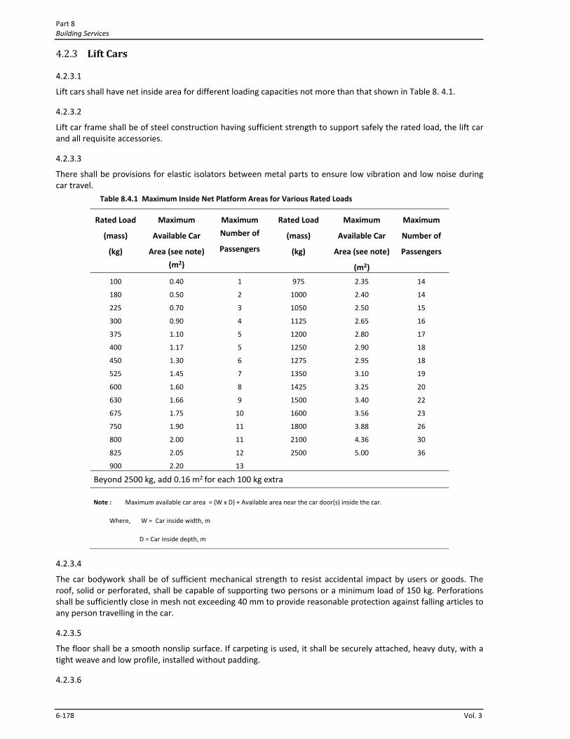
4.2.3.1
Lift cars shall have net inside area for different loading capacities not more than that shown in Table 8. 4.1.
4.2.3.2
Lift car frame shall be of steel construction having sufficient strength to support safely the rated load, the lift car and all requisite accessories.
4.2.3.3
There shall be provisions for elastic isolators between metal parts to ensure low vibration and low noise during car travel.
Table 8.4.1 Maximum Inside Net Platform Areas for Various Rated Loads
Rated Load
(mass)
(kg)
Maximum
Available Car
Area (see note)
(m2)
Maximum
Number of
Passengers
Rated Load
(mass)
(kg)
Maximum
Available Car
Area (see note)
(m2)
Maximum
Number of
Passengers
100
180
225
300
375
400
450
525
600
630
675
750
800
825
900
0.40
0.50
0.70
0.90
1.10
1.17
1.30
1.45
1.60
1.66
1.75
1.90
2.00
2.05
2.20
1
2
3
4
5
5
6
7
8
9
10
11
11
12
13
975
1000
1050
1125
1200
1250
1275
1350
1425
1500
1600
1800
2100
2500
2.35
2.40
2.50
2.65
2.80
2.90
2.95
3.10
3.25
3.40
3.56
3.88
4.36
5.00
14
14
15
16
17
18
18
19
20
22
23
26
30
36
Beyond 2500 kg, add 0.16 m2 for each 100 kg extra
Note : Maximum available car area = (W x D) + Available area near the car door(s) inside the car.
Where, W = Car inside width, m
D = Car inside depth, m
4.2.3.4
The car bodywork shall be of sufficient mechanical strength to resist accidental impact by users or goods. The roof, solid or perforated, shall be capable of supporting two persons or a minimum load of 150 kg. Perforations shall be sufficiently close in mesh not exceeding 40 mm to provide reasonable protection against falling articles to any person travelling in the car.
4.2.3.5
The floor shall be a smooth nonslip surface. If carpeting is used, it shall be securely attached, heavy duty, with a tight weave and low profile, installed without padding.
4.2.3.6
Lifts, Escalators and Moving Walks Chapter 4
Bangladesh National Building Code 2011 6‐179
A handrail shall be provided on at least one wall of the car, preferably the rear. The rails shall be smooth and the inside surface at least 38 mm clear of the walls at a nominal height of 800 mm from the floor.
4.2.3.7
Height of the entrance to the lift car shall not be less than 2 m.
4.2.3.8
The lift car doors, shall be power operated horizontally sliding type (noncollapsible), opened and closed by automatic means. However, if space is limited, collapsible doors may be installed in case of buildings not exceeding 8 storeys or 26 m in height, but they shall not be power operated. Sliding doors shall be guided at top and bottom. Means shall be provided to prevent all sliding doors from jumping off the tracks and suitable stops shall be provided to prevent the hanger carriage from leaving the end of the track.
4.2.3.9 Lift Door Safeties
(a) Car and landing doors shall open and close in full synchronization being mechanically connected to each other.
(b) Doors closed by automatic means shall be provided with door reopening device(s) which will function to stop and reopen a car door and adjacent landing door in case the car door is obstructed while closing. The reopening device shall also be capable of sensing an object or person in the path of a closing door without requiring contact for activation. Door reopening devices shall remain effective for a period of not less than 20 seconds. The operating mechanism for the car door shall not exert a force more than 125 N.
(c) Car doors shall be equipped with efficient interlocking or other devices so that the door cannot be opened except when the lift car is at the landing, and that the lift car cannot be moved away from the landing until the leading edge of the single slide or double speed door is within 50 mm of the nearest face of the door jamb or the leading edges of the centre opening doors are within 50 mm of contact of each other.
4.2.3.10
Lift car doors, when closed, shall cover the opening fully except in the case of vertical biparting car doors of goods lifts.
4.2.3.11
Where the lift car has solid enclosure and doors, provision shall be made for a fan for adequate ventilation. To permit switching off the power supply to the lift without switching off the fan and light, a separate switch shall be provided for fan and light.
4.2.3.12
Any vision panel in a car door shall be fire resisting and shall be of safety wired glass or similar material. The area between division bars or other supports shall not exceed 0.1 m2. The bottom rail of a framed and glazed door shall be not less than 300 mm deep. Any projections on or recesses (including vision panels) in sliding car doors shall be kept to a minimum in order to avoid finger trapping between sliding parts of the door and any fixed part of the structure.
4.2.3.13
The lift car shall be provided with a self leveling feature that will automatically bring the car to the floor landing within a tolerance of + 13 mm under normal loading and unloading conditions. This self‐leveling shall, within its zone, be entirely automatic and independent of the operating device and shall correct the over‐travel or under‐travel. The car shall also be maintained approximately level with the landing, irrespective of load. Where no self‐leveling device is provided, the leveling difference between the car and the landing shall be within + 40 mm.
4.2.3.14
Car operating panels shall be conveniently located on the side near the door so that passengers can register calls as quickly as possible. The centre line of the alarm button and emergency stop switch shall be at a nominal height of 890 mm, and the highest floor button no higher than 1.37 m from the floor. Floor registration buttons,
Part 8 Building Services
6‐180 Vol. 3
exclusive of border, shall be a minimum of 18 mm in size, raised, flush or recessed. Visual indication shall be provided to show each call registered and extinguished when the call is answered. Depth of flush or recessed buttons when operated shall not exceed 10 mm. Markings shall be adjacent to the controls on a contrasting colour background to the left of the controls; letters or numbers shall be a minimum of 15 mm high and raised or recessed 0.75 mm. Sign plates permanently attached shall be acceptable. Emergency controls shall be grouped together at the bottom of the panel.
4.2.3.15
A suitable battery operated alarm system shall be installed inside the lift car so as to raise an alarm at a convenient place for getting assistance for passengers trapped inside the lift car.
4.2.3.16
A car position indicator shall be provided above the car operating panel or over the opening of each car to show the position of the car in the lift well by illuminated visual indicator corresponding to the landing at which the car is stopped or through which it is passing.
In addition, an audible signal shall preferably be installed which shall sound to tell a passenger that the car is stopping at a floor served by the lift. A special button located with emergency controls may be provided, operation of which shall activate an audible signal only for the desired trip.
4.2.3.17
Each lift car shall be fitted with a light and the car shall be kept illuminated during the whole period the lift is available for use.
4.2.3.18
In installations with more than two lifts in a bank, a telephone or other device for two‐way communication between each lift car and a convenient point outside the lift well shall preferably be provided. Markings or the international symbol for telephones shall be placed adjacent to the control on a contrasting colour background.
4.2.4 Lift Well and Lift Well Enclosures
4.2.4.1
The Lift well shall only be used for housing equipment forming part of the lift installation or for its operation and maintenance. No other equipment or services shall be accommodated therein. For this purpose, the main electric supply line for lift machine shall be deemed to be part of the lift and the electric cable, if laid along the lift well shaft, shall be properly clamped to the wall.
4.2.4.2
The lift well shall not form part of the ventilation system of the building.
4.2.4.3
In multi‐story residential buildings, hotels and hospitals, lift well shall be isolated from sleeping rooms (bed rooms) by lobbies or other spaces.
4.2.4.4
Lift well shall not be located above any room, passage or thoroughfare. However, when absolutely necessary, this can only be permissible with the prior approval of the competent authority and in such case the following provisions shall be made:
(a) The pit shall be sufficiently strong to withstand the impact of the lift car with the rated load or the impact of the counterweight when either of these is descending at the rated speed or at governor tripping speed;
(b) Spring or oil buffers shall be provided for lift car and counterweight; and (c) The car and counterweight shall be provided with a governor operated safety gear.
4.2.4.5
Lifts, Escalators and Moving Walks Chapter 4
Bangladesh National Building Code 2011 6‐181
When there are three or fewer lift cars in a building, they may be located within the same lift well enclosure. When there are four lift cars, they shall be divided in such a manner that at least two separate lift well enclosures are provided. When there are more than four lifts, not more than four lift cars may be located within a single lift well enclosure.
4.2.4.6
The lift car and its counterweight shall travel in juxtaposition to each other.
4.2.4.7 Totally Enclosed Wells
The enclosure of the totally enclosed wells shall be continuous and shall extend on all sides from floor to floor or stair to stair. No openings except for doors at landings and necessary access panels shall be provided. The enclosure shall be of sufficient mechanical strength to support the lift guides at appropriate intervals and to support in true alignment the landing doors with operating mechanisms and locking devices.
4.2.4.8 Open Type Wells
(a) When Lift well enclosures are constructed of wire grille or similar material, the mesh opening shall not be greater than 30 mm (except for door at landings). Such enclosures shall be of sufficient strength to resist accidental impact by users of adjoining areas or by materials or vehicles being moved in the vicinity.
(b) Where the clearance between the inside of an open type lift well enclosure and any moving or movable part of the lift equipment or apparatus is less than 50 mm, the openings in the enclosure material shall not be more than 10 mm. Larger openings up to 30 mm shall be permissible provided it is further protected by square mesh netting with aperture of not greater than 10 mm and wire not smaller than 1 mm in diameter.
4.2.4.9
There shall be no opening in the lift well enclosure for access to the lift well through the space under the counterweight.
4.2.4.10
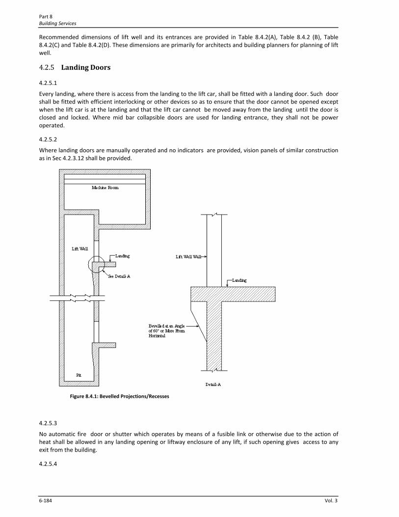
The inside surfaces of the lift well enclosures facing any car entrance shall form a smooth continuous flush surface devoid of projections or recesses. Where projections or recesses cannot be avoided, the underside of these projections/recesses shall be bevelled to an angle of 60 degrees from the horizontal by means of metal plates or other fire resistive materials as shown in Fig 8.4.1.
4.2.4.11
Sufficient clearance space shall be provided between the guides for the car and the side walls of the lift well enclosure to allow safe and easy access to the parts of the safety gears for their maintenance and repairs.
4.2.4.12
Maximum clearance between the inner surface of well enclosure on the landing door side and any part of car facing the surface shall be 150 mm except that 230 mm and 200 mm clearance will be permissible when power operated vertically bi‐parting landing doors or two speed horizontally sliding doors are installed respectively.
4.2.4.13
Each lift well serving more than two floors shall have vent(s) properly located at the top of the exterior wall. The vents shall be louvered with birds screens. If the well is located in such a way that no exterior wall is available for louvers, vents with connecting noncombustible ducts to an outside wall shall be provided. The area of vent shall not be less than 3.5% of the area of the lift well, provided that a minimum of 0.3 m2 per lift is provided. Of the total required vent area not less than one‐third shall be permanently open or automatically opened by a damper.
4.2.4.14 Bottom car clearance, Passenger and Service Lift
When the car rests on its fully compressed buffer there shall be a vertical clearance of not less than 600 mm between the pit floor and the buffer striker plate or the lowest structural or mechanical part equipment or device installed. The clearance shall be available beneath the whole area of the platform except for:

Part 8 Building Services
6‐182 Vol. 3
(a) guide shoes or rollers, safety jaw blocks, platform aprons, guards of other equipment located within 300 mm measured horizontally from the sides of the car platform; and
(b) compensating sheaves. Provided that in all the cases, including small cars, a minimum clearance of 600 mm is available over a horizontal area of 800 mm x 500 mm.
Provided also that in all the cases, when the car rests on its fully compressed buffers, there shall be a vertical clearance of not less than 50 mm between any part of the car and any obstruction of device mounted in the pit.
4.2.4.15 Top car clearance, Passenger and Service Lift
The vertical clearance between the car cross‐head and the nearest overhead obstruction within 500 mm measured horizontally to the nearest part of the crosshead when the car platform is level with the top landing, shall be not less than the sum of the following;
(a) The bottom counterweight runby.
(b) The stroke of the counterweight buffer used. (c) One‐half of the gravity stopping distance based on:
i. 115 percent of the rated speed where oil buffers are used and no provision is made to prevent the jump of the car at counterweight buffer engagement; and
ii. Governor tripping speed where spring buffers are used.
NOTE — The gravity stopping distance based on the gravity retardation from any initial velocity may be calculated according to the following formula
S = 51 V2
where
S = Free fall in mm (gravity stopping distance), and
V = Initial velocity in m/s
(d) 600 mm.
Where there is a projection below the ceiling of the well and the projection is more than 500 mm, measured horizontally from the centre line of the cross‐head but over the roof of the car, a minimum vertical clearance not less than that calculated above shall also be available between the roof of the car and the projection.
Provided that the vertical clearance between any equipment mounted on top of the car and the nearest overhead obstruction shall be not less than the sum of the three items (a), (b) and (c) as calculated above plus 150 mm
4.2.4.16 Bottom Runby for Cars and Counterweights, passenger and service lift
The bottom runby of cars and counterweights shall be not less than the following: (a) 150 mm where oil buffers are used;
(b) Where spring‐buffers are used;
i. 150 mm for controls as in 5.1.3.17(d) to 5.1.3.17(h)
ii. Not less than the following for controls as in 5.1.3.17(a) to 5.1.3.17©.
Rated speed Runby
m/s mm
Up to 0.125 75
0.125 to 0.25 150
0.25 to 0.50 225
0.50 to 1 300
4.2.4.17 Maximum Bottom Runby, passenger and service lift
Lifts, Escalators and Moving Walks Chapter 4
Bangladesh National Building Code 2011 6‐183
In no case the maximum bottom runby shall exceed the following:
(a) 600 mm for cars; and
(b) 900 mm for counterweights.
4.2.4.18 Top Counterweight Clearances, passenger and service lift
The top counterweight clearance shall be not less than the sum of the following four items:
(a) the bottom car runby;
(b) the stroke of the car buffer used; (c) 150 mm; and
(d) one‐half the gravity stopping distance based on i. one hundred and fifteen percent of the rated speed where oil buffers are used and no provision
is made to prevent jump of the counterweight at car buffer engagement; and
ii. governor tripping speed where spring buffers are used.
4.2.4.19 Top car clearance, Goods lift
The top car clearance shall be sufficient to avoid any protruding part fixed on the top of the car coming in direct contact with the ceiling or diverting sheave.
The clearance shall be calculated taking into account the following and shall not be less than the sum of the following four items:
(a) The bottom counterweight runby,
(b) The stroke of the counterweight buffer used, (c) The dimensions of the portion of the diverting sheave hanging underneath the ceiling in the lift well,
and
(d) 150 mm for compensating for gravity stopping distance and future repairs to the rope connections at counter weight and at the car or at the suspension points.
4.2.4.20 Bottom car clearance, goods lift
The bottom car clearance shall be maintained in such a way that the counterweight shall not come in contact with the ceiling or any part hanging underneath the ceiling, when the car completely rests on fully compressed buffers, provided the buffers are spring type mounted on solid concrete or steel bed.
In case of wooden buffers the bottom car clearance shall be maintained in such a way that the total downward travel of the car from the service level of the immediate floor near the pit, shall not be more than the top counterweight clearance, when the wooden buffers are completely crushed.
4.2.4.21 Top counterweight clearance, goods lift
The top clearance for the counterweight can be calculated taking into account the following and shall not be less than the sum of the following three items:
(a) Car runby, (b) Compression of the buffer spring or height of the wooden block used as buffer, and
(c) 150 mm to compensate for gravity stopping distance for counterweight and any future repairs to rope connections at the counterweight at the car ends or at the suspension points.
4.2.4.22 Runby for Cars and Counterweights, goods lift
The bottom runby for cars and counterweights shall not be less than 150 mm
4.2.4.23 Maximum bottom runby, goods lift
In no case the maximum bottom runby shall exceed 300 mm.
4.2.4.24 Overhead Height
The overhead height shall not be less than as shown in Table 8.4.2
4.2.4.25 Lift well dimensions
Part 8 Building Services
6‐184 Vol. 3
Recommended dimensions of lift well and its entrances are provided in Table 8.4.2(A), Table 8.4.2 (B), Table 8.4.2(C) and Table 8.4.2(D). These dimensions are primarily for architects and building planners for planning of lift well.
4.2.5 Landing Doors
4.2.5.1
Every landing, where there is access from the landing to the lift car, shall be fitted with a landing door. Such door shall be fitted with efficient interlocking or other devices so as to ensure that the door cannot be opened except when the lift car is at the landing and that the lift car cannot be moved away from the landing until the door is closed and locked. Where mid bar collapsible doors are used for landing entrance, they shall not be power operated.
4.2.5.2
Where landing doors are manually operated and no indicators are provided, vision panels of similar construction as in Sec 4.2.3.12 shall be provided.
Figure 8.4.1: Bevelled Projections/Recesses
4.2.5.3
No automatic fire door or shutter which operates by means of a fusible link or otherwise due to the action of heat shall be allowed in any landing opening or liftway enclosure of any lift, if such opening gives access to any exit from the building.
4.2.5.4
Lifts, Escalators and Moving Walks Chapter 4
Bangladesh National Building Code 2011 6‐185
In case of passenger lifts, solid sliding doors shall preferably be provided for buildings above six storeys or 20 m in height. Solid swing doors may also be used where sliding space is not available parallel to the entrance door. Collapsible doors shall not be provided in case of buildings above eight storeys or 26 m in height.
4.2.6 Guide Rails
4.2.6.1
Guide rails shall be made of high quality steel, straight and of proper thickness. Where the nature of processes carried on in the building gives rise to acid fumes or corrosive substances the steel rails shall be treated for corrosion resistance.
4.2.6.2
Car and counterweight guide rails shall be continuous throughout the entire length right from the bottom of the pit floor to the top most floor served plus additional length as may be required for operation of safety against over run. They shall be provided with adequate brackets or equivalent fixing devices of such design and spacing that the rails shall not deflect more than 4 mm under normal operations
4.2.6.3
For passenger and goods lifts having a rated speed of 0.5 m/s or more, the car guide rails shall have working surfaces machined and smooth.
4.2.7 Lift Pits
4.2.7.1
A lift pit shall be provided at the bottom of every lift well. The minimum depth of lift pit shall be as shown in Table 8.4.2.
4.2.7.2
Lift pits shall be of sound construction and shall be maintained in dry and clean condition. Where necessary, provision shall be made for permanent drainage.
4.2.7.3
Lift pits having depth more than 1.6 m shall be provided with a suitable descending arrangement to reach the lift pit.
4.2.7.4
Light points shall be provided in all lift pits for facility of repair and maintenance works.
4.2.7.5
In case of a group of two or more lift wells, arrangements shall be provided to allow inspection of a lift pit through the adjoining one.

Part 8 Building Services
6‐186 Vol. 3
Table 8.4.2 Minimum Pit Depths, Overhead Heights and Machine Room sizes for Traction Lifts ‐ Overhead Machines
Speed (m/s) Up to
0.70
>0.70
≤1.00
>1.00
≤1.50
>1.50
≤1.75
>1.75
≤2.00
>2.00
≤2.50
>2.50
≤3.00
>3.00
≤4.00
i)Pit Depth, mm
ii)Overhead Height, mm
iii) Machine room Depth, mm
iv) Machine Room width, mm
1500
4200
D +
2000
C +
1000
1500
4250
D +
2000
C +
1000
1600
4800
D +
2000
C +
1200
2150
4800
D +
2500
C +
1200
2200
5200
D +
2500
C +
1500
2500
5400
D +
2500
C +
1500
3000
‐
D +
3000
C +
1800
3200
‐
D + 3000
C +
1800
NOTES :
1. C is lift well depth (mm) and D is lift well width (mm).
2. The total overhead height has been calculated on the basis of car height of 2300mm.
3. Dimensions of pit depth and overhead height may differ in practice as per individual manufacturer's design depending upon load,
speed and drive. However, the pit depth and overhead height shall be such as to conform to the requirements of bottom clearance
and top clearance In accordance with the accepted standard.
Table 8.4.2(A) Recommended Dimensions of Passenger & Service Lifts and Lift Wells
Capacity Car Dimensions
(mm)
Lift Well Dimensions
(mm)
Entrance
Size (mm)
Persons Kg Width Depth Width Depth
4 272 1100 700 1900 1300 700 (Min)
6 408 1100 1000 1900 1700 700 (Min)
8 544 1300 1100 1900 1900 800
10 680 1300 1350 1900 2100 800
13 884 2000 1100 2500 1900 900
16 1088 2000 1300 2500 2100 1000
20 1360 2000 1500 2500 2400 1000
Notes :
1. In case of manually operated doors, clear entrance will be reduced by the amount of projection of handle on the landing.
2. All dimensions given above for lifts having centre opening power operated doors with counterweight at rear, are recommended dimensions primarily for architects and building planners. Any variations mutually agreed between the manufacturer and purchaser are permitted. However variation in :
(a) Car inside dimensions shall be within the maximum area limits specified in accordance with Table 8.4.1
(b) Entrance width on the higher side Is permitted.
(c) Entrance width may be reduced up to a maximum of 100 mm subject to a minimum of 700 mm.
Table 8.4.2(B) Recommended Dimensions of Goods Lifts and Lift Wells
Load (Kg) Car Dimensions (mm) Lift Well Dimensions
(mm)
Entrance
Size (mm)
Width Depth Width Depth
500 1100 1200 1900 1500 1100

Lifts, Escalators and Moving Walks Chapter 4
Bangladesh National Building Code 2011 6‐187
1000 1400 1800 2300 2100 1400
1500 1700 2000 2600 2300 1700
2000 1700 2500 2600 2800 1700
2500 2000 2500 2900 2800 2000
3000 2000 3000 2900 3300 2000
4000 2500 3000 3400 3300 2500
5000 2500 3600 3400 3900 2500
Notes :
1. The width of lift machine room shall be equal to be lift well width subject to a minimum of 2500 mm.
2. Clear entrance width is based on vertical lifting car door and vertical bi‐parting landing doors. For collapsible mid‐bar doors the
clear entrance width will be reduced by 200 mm (maximum 1800 mm).
3. All dimensions given above are recommended dimensions primarily for architects and building planners. Any variations mutually
agreed between the manufacturer and the purchaser are permitted. However, variation in car inside dimensions shall be within the
maximum area limits in accordance with Table 8.4.1.
4. For dimensions of pit depth and overhead height, consider data shown in Table 8.4.2.
Table 8.4.2(C) Recommended Dimensions of Hospital Lifts and Lift Wells
Capacity Car Dimensions
(mm)
Lift Well Dimensions
(mm)
Entrance
Size (mm)
Persons Kg Width Depth Width Depth
12 1020 1000 2400 1800 3000 800
20 1360 1300 2400 2200 3000 1200
26 1768 1600 2400 2400 3000 1200
Notes :
1. In the case of manually operated doors, clear entrance will be reduced by the amount of projection of handle on the landing door.
2. Although 15 persons capacity lift is not standard one, this is included to cover lifts of smaller capacity which can be used in small
hospitals.
3. All dimensions given above are recommended dimensions primarily for architects and building planners. Any variations mutually
agreed between the manufacturer and the purchaser are permitted. However, variation in car inside dimensions shall be within the
maximum area limits in accordance with Table 8.4.1.
4. For dimensions of pit depth and overhead height, consider data shown in Table 8.4.2.
Table 8.4.2(D) Recommended Dimensions of Dumb Waiter and Lift Wells (for speeds up to 0.5 m/s)
Load
(Kg)
Car Inside Dimensions (mm) Lift Well Dimensions
(mm)
Entrance
Size (mm)
Width Depth Height Width Depth
100 700 700 800 1200 900 700
150 800 800 900 1300 1000 800
200 900 900 1000 1400 1100 900
250 1000 1000 1200 1500 1200 1000
Notes :
1. Entrance width is based on assumption of provision of vertical bi‐parting doors ( no car door is normally provided).
4.2.8 Buffers
4.2.8.1
Buffers of spring or oil shall be used for safety. Buffers shall be fitted under the lift car and counterweight directly or on the pit floor with suitable concrete or steel foundation. Oil resistant rubber buffers may be used with lifts
Part 8 Building Services
6‐188 Vol. 3
having a rated speed not exceeding 0.25 m/s. Lifts having rated speed in excess of 0.25 m/s and up to and including 1.0 m/s, spring or oil buffers shall be used. For lifts having rated speed more than 1.0 m/s, only oil buffers shall be used. Wooden blocks suitably treated may also be used for service lifts for speeds up to 0.5 m/s. Buffers shall be located symmetrically with reference to the vertical centreline of the car/counterweight with a tolerance of 50 mm.
4.2.8.2
The minimum stroke of oil buffers shall be such that the car or the counterweight on striking the buffers at 115 per cent of rated speed shall be brought to rest with an average retardation of not more than 10 m/s2.
4.2.8.3
When buffers are struck with an initial speed of less than 115 per cent of the rated speed, the peak retardation shall not exceed 25 m/s2 for a duration more than 0.04 second, with any load in the car ranging from 75 kg to the rated load.
4.2.9 Machine Room and Overhead Structures
4.2.9.1
The lift machine room shall only be used for housing lift machinery, controller and other associated apparatus and equipment. No other services or equipment shall be accommodated therein. If motor‐generators for controlling speed of multi‐voltage or variable voltage machines, secondary sheaves, pulleys, governors, floor selecting equipment and other associated equipment are installed in an adjoining room, this room shall also be reserved for exclusive use of lift equipment.
4.2.9.2
Lift machine room and other associated equipment rooms shall be fire proof, weather proof and adequately lighted. Means to prevent spread of fire or smoke from machine room into lift well shall be provided. Machine room shall have permanent ventilation opening direct to the open air having a free area not less than 0.1 m2 per lift. The ambient temperature of machine room shall be maintained between +5ºC and +40ºC
4.2.9.3
The height of the machine room shall not be less than 2.30 m throughout under the lifting beam (trolley beam) to allow any portion of equipment to be accessible and removable for repair and replacement. An overhead trolley beam of steel construction of adequate strength shall be provided in the machine room, for movement of equipment during installation.
4.2.9.4
The machine room shall be adequately sized and shall have sufficient floor area required for easy access to all parts of the machines and equipment located therein for purposes of inspection, maintenance or repair. Clearance space of 1 m shall be provided on those sides of control panels where maintenance is required to be carried out while the panel is energized, otherwise 0.5 m clearance space may be provided. For planning purposes the lift machine room size can be as shown In Table 8.4.2
4.2.9.5
The room shall be kept closed, except to those who are concerned with the operation and maintenance of the equipment. When the electrical voltage exceeds 220/230V dc, a danger notice plate shall be displayed permanently on the outside of the door and on or near the machinery.
4.2.9.6
Machine room floor shall not have holes/punches in it except for necessary small openings for passage of ropes cables etc. If any machine room floor or platform does not extend to the enclosing walls the open sides shall be provided with hand rails or otherwise suitably guarded.
4.2.9.7
All machines, pulleys, overspeed governors and similar units shall be securely fixed on the machine room floor.

Lifts, Escalators and Moving Walks Chapter 4
Bangladesh National Building Code 2011 6‐189
4.2.9.8
Adequate artificial light shall be provided in the machine room. A 15 amps 3 pin power outlet for hand operated tools and a 5 amps 2 pin electrical outlet for portable hand lamp set shall be provided in the machine room.
4.2.9.9 Access to Machine Room
(a) The machine room shall be provided with a direct, independent and convenient access. Access to a machine room above a lift well may be either from the roof or by an internal staircase.
(b) Machine room floor may be provided with a trap door. When access to the machine room is provided through the trap door, the size of the trap door shall not be less than 1.0 m x 1.0 m otherwise it may be 0.5 m x 0.5 m. Trap doors shall be hinged, opening into the machine room, of sound construction, balanced and tightly secured to minimize noise travel. Hand rails shall be provided around trap door opening .
(c) Where a machine room entrance is less than 1.5 m above or below the adjacent floor or roof surface, a substantial permanently attached ladder may be used.
(d) Where the machine room entrance is 1.5 m or more above or below the adjacent floor or roof surface, access shall be provided by means of standard stairs.
(e) Access to a machine room in a basement may be provided from a corridor.
(f) Access to a machine room via the lift well shall be prohibited.
(g) Emergency exit shall be provided in case of large machine room having four or more lifts.
4.2.9.10
The space at secondary level in which the overhead pulleys, overspeed governors and similar machinery are housed shall have a clear height of at least 1.2 m. Where practicable, it shall have a substantial platform or floor and be provided with permanent and adequate artificial illumination. Safe and convenient access to secondary level shall be provided. Means of access between a secondary floor and machine room may be a ladder. Hand rails shall be provided at platform and access to floor.
4.2.10 Hall Buttons, Hall Lanterns and Special Signs
4.2.10.1 Hall Buttons
(a) Each landing shall have hall call buttons to register call for lift service for upward or downward movements. The centre line of the hall call buttons shall be at a nominal height of 1 m above the floor.
(b) Direction buttons, exclusive of borders, shall be a minimum of 18 mm in size, raised, flush or recessed. Visual indication shall be provided to show each call registered and extinguished when the call is answered. Depth of flush or recessed button when operated shall not exceed 10 mm.
4.2.10.2 Hall Lantern
(a) Where lifts are installed in totally enclosed wells, a visual signal shall be provided at each lift well entrance indicating to the prospective passenger the car answering the call and its direction of travel. An audible signal may also be included.
(b) The visual signal may be in the form of digital lift position indicator or directional indicator. The visual signal for each direction/lift position shall be a minimum of 62 mm in size and visible from the proximity of the hall call buttons.
(c) The centre line of the fixture shall be located at a minimum of 1.8 m from the floor.
4.2.10.3 Special Signs
(a) Door Jamb Marking : The floor designation shall be provided at each lift well entrance on both sides of jamb visible from within the car and the lift lobby at a height of 1.5 m above the floor. Designations shall be on a contrasting background 50 mm high and raised 0.75 mm.
(b) Applied plates permanently attached shall be acceptable. In case of a completely enclosed lift well a notice with the word 'Lift' shall be placed outside of each landing door. Electric light shall be provided such that this sign remains visible even if the surroundings are dark

Part 8 Building Services
6‐190 Vol. 3
(c) A permanent warning sign shall be installed immediately above each hall push button station on each floor reading : IN FIRE EMERGENCY, DO NOT USE LIFT. USE EXIT STAIRS. This sign shall be in letters not less than 12 mm high.
The warning sign may consist of incised, inlaid or embossed letters on a metal, wood, plastic or similar plate securely and permanently attached to the wall, or letters incised or inlaid directly into the surface of the material forming the wall.
4.2.11 Electrical Wiring and Apparatus
4.2.11.1
Construction, installation and maintenance of all electrical supply lines and apparatus in connection with lift installation shall be done with proper protection so that there may be no danger to persons there from. No bare conductor shall be used in any lift car. Installation of electrical wiring shall conform to the provisions of Chapter 1.
4.2.11.2
Electrical circuits for lights and ventilation fans, and supply to 3 pin and 2 pin socket outlets shall be controlled by a separate main switch or circuit breaker, and shall be independent of machinery power supply such that lighting circuits remain alive when power to machinery is interrupted.
4.2.11.3
Suitable cautionary notice shall be affixed near every motor or other apparatus in which energy used is at a voltage exceeding 220 volts.
4.2.11.4 Travelling Cable
(a) Circuits which supply current to the motor shall not be included in any twin or multi‐core travelling cable used in connection with the control and safety devices.
(b) A travelling cable which incorporates conductors for the control circuits shall be separate and distinct from that which incorporates lighting and signalling circuits in case of buildings ten storeys (32 m) or less in height. In case of buildings more than ten storeys or 32 metres in height or where high speed (1.50 m/s or more) lifts are employed, use of a single travelling cable for lighting and control circuits shall be permitted, provided that all conductors are insulated for the maximum voltage in the cables.
4.2.11.5 Supply Cables and Switches
(a) Each lift shall be provided with a main switch or circuit breaker of a capacity determined by the lift manufacturer and the incoming supply cable shall terminate in this switch. For a single lift, this switch shall be fixed adjacent to the machine room entrance. In a machine room common to more than one lift, each main switch shall be conveniently situated with respect to the lift it controls. Switches and fuses (which may form part of a distribution switch board) shall be provided for isolating the supply power to the machine room.
(b) Where a supply cable serves more than one lift, a diversity factor may be used for the determination of conductor size. The actual diversity factor to be adopted shall be decided by the lift manufacturer.
4.2.11.6 Earthing
All electrical machinery/equipment viz. electric motor, winding machine, control panel etc. which normally carry mains current shall be properly connected to the earthing system. Similarly all metallic cases, covers of door interlocks, door contacts, call and control buttons, stop buttons, car switches, limit switches, junction boxes and similar electrical fittings which normally carry only the control current shall also be properly connected to the earthing system. All earthing terminal and earthing conductors in this regard shall conform to the requirements of Chapter 1.
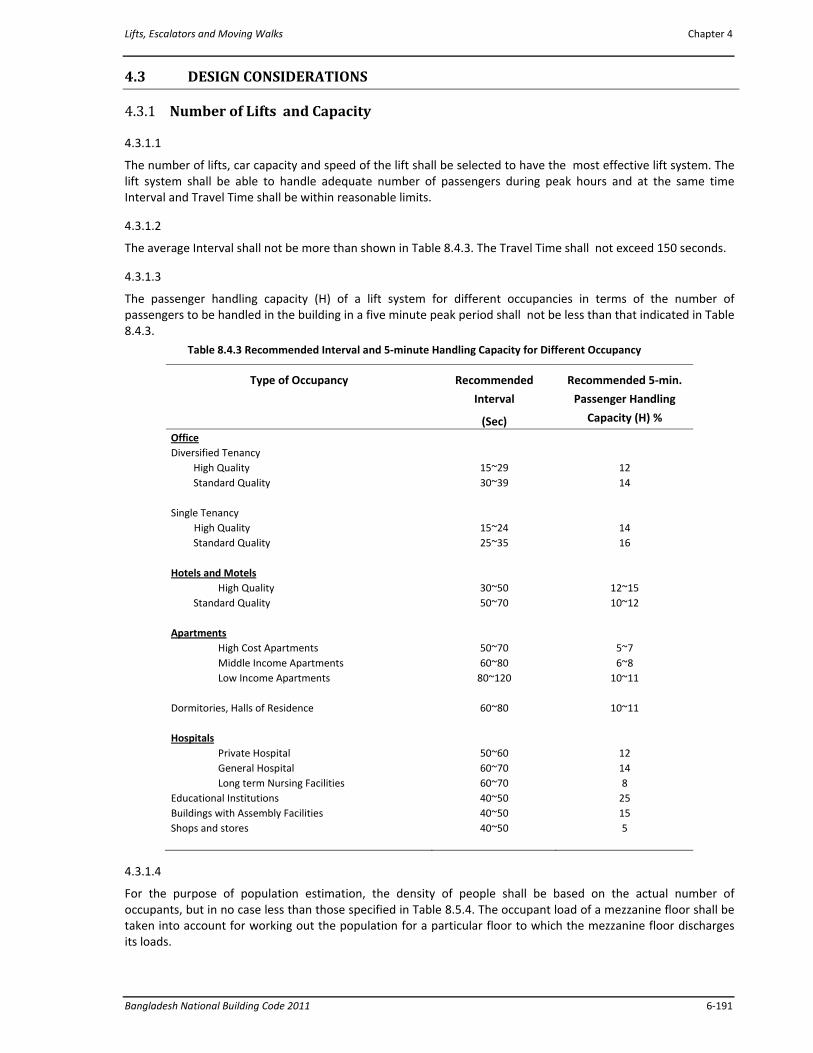
Lifts, Escalators and Moving Walks Chapter 4
Bangladesh National Building Code 2011 6‐191
4.3 DESIGN CONSIDERATIONS
4.3.1 Number of Lifts and Capacity
4.3.1.1
The number of lifts, car capacity and speed of the lift shall be selected to have the most effective lift system. The lift system shall be able to handle adequate number of passengers during peak hours and at the same time Interval and Travel Time shall be within reasonable limits.
4.3.1.2
The average Interval shall not be more than shown in Table 8.4.3. The Travel Time shall not exceed 150 seconds.
4.3.1.3
The passenger handling capacity (H) of a lift system for different occupancies in terms of the number of passengers to be handled in the building in a five minute peak period shall not be less than that indicated in Table 8.4.3.
Table 8.4.3 Recommended Interval and 5‐minute Handling Capacity for Different Occupancy
Type of Occupancy Recommended
Interval
(Sec)
Recommended 5‐min.
Passenger Handling
Capacity (H) %
Office Diversified Tenancy High Quality Standard Quality Single Tenancy High Quality Standard Quality Hotels and Motels
High Quality Standard Quality Apartments
High Cost Apartments Middle Income Apartments Low Income Apartments
Dormitories, Halls of Residence Hospitals
Private Hospital General Hospital Long term Nursing Facilities
Educational Institutions Buildings with Assembly Facilities Shops and stores
15~29 30~39
15~24 25~35
30~50 50~70
50~70 60~80 80~120
60~80
50~60 60~70 60~70 40~50 40~50 40~50
12 14
14 16
12~15 10~12
5~7 6~8
10~11
10~11
12 14 8 25 15 5
4.3.1.4
For the purpose of population estimation, the density of people shall be based on the actual number of occupants, but in no case less than those specified in Table 8.5.4. The occupant load of a mezzanine floor shall be taken into account for working out the population for a particular floor to which the mezzanine floor discharges its loads.
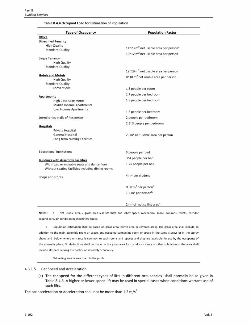
Part 8 Building Services
6‐192 Vol. 3
Table 8.4.4 Occupant Load for Estimation of Population
Type of Occupancy Population Factor Office Diversified Tenancy High Quality Standard Quality Single Tenancy
High Quality Standard Quality Hotels and Motels
High Quality Standard Quality
Conventions Apartments
High Cost Apartments Middle Income Apartments Low Income Apartments
Dormitories, Halls of Residence Hospitals
Private Hospital General Hospital Long term Nursing Facilities
Educational Institutions Buildings with Assembly Facilities
With fixed or movable seats and dance floor Without seating facilities including dining rooms
Shops and stores
14~23 m2 net usable area per persona
10~12 m2 net usable area per person
12~19 m2 net usable area per person
8~10 m2 net usable area per person
1.3 people per room
1.7 people per bedroom
1.9 people per bedroom
1.5 people per bedroom
2 people per bedroom
2.5~3 people per bedroom
20 m2 net usable area per person
3 people per bed
3~4 people per bed
1.75 people per bed
4 m2 per student
0.60 m2 per personb
1.5 m2 per personb
2 m2 of net selling areac
Notes : a Net usable area = gross area less lift shaft and lobby space, mechanical space, columns, toilets, corridor
around core, air‐conditioning machinery space.
b Population estimation shall be based on gross area (plinth area or covered area). The gross area shall include, in
addition to the main assembly room or space, any occupied connecting room or space in the same storeys or in the storey
above and below, where entrance is common to such rooms and spaces and they are available for use by the occupants of
the assembly place. No deductions shall be made in the gross area for corridors, closets or other subdivisions, the area shall
include all space serving the particular assembly occupancy.
c Net selling area is area open to the public.
4.3.1.5 Car Speed and Acceleration
(a) The car speed for the different types of lifts in different occupancies shall normally be as given in Table 8.4.5. A higher or lower speed lift may be used in special cases when conditions warrant use of such lifts.
The car acceleration or deceleration shall not be more than 1.2 m/s2 .
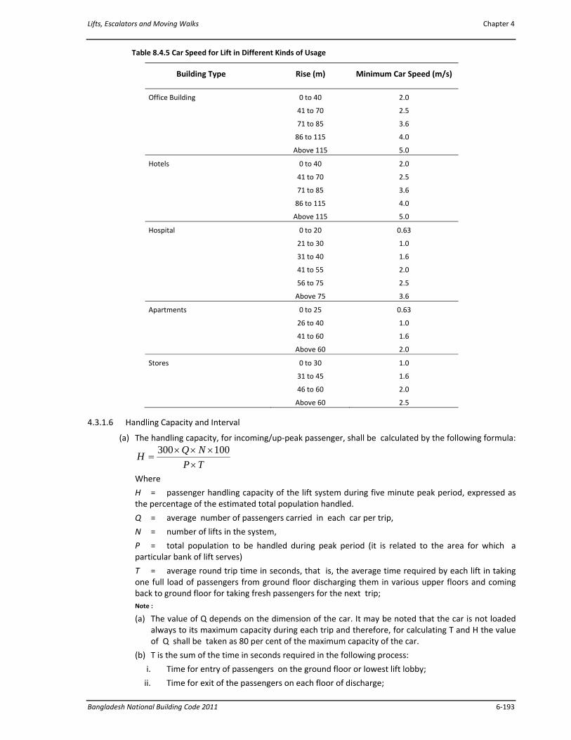
Lifts, Escalators and Moving Walks Chapter 4
Bangladesh National Building Code 2011 6‐193
Table 8.4.5 Car Speed for Lift in Different Kinds of Usage
Building Type Rise (m) Minimum Car Speed (m/s)
Office Building 0 to 40
41 to 70
71 to 85
86 to 115
Above 115
2.0
2.5
3.6
4.0
5.0
Hotels 0 to 40
41 to 70
71 to 85
86 to 115
Above 115
2.0
2.5
3.6
4.0
5.0
Hospital 0 to 20
21 to 30
31 to 40
41 to 55
56 to 75
Above 75
0.63
1.0
1.6
2.0
2.5
3.6
Apartments 0 to 25
26 to 40
41 to 60
Above 60
0.63
1.0
1.6
2.0
Stores 0 to 30
31 to 45
46 to 60
Above 60
1.0
1.6
2.0
2.5
4.3.1.6 Handling Capacity and Interval
(a) The handling capacity, for incoming/up‐peak passenger, shall be calculated by the following formula:
TPNQH
××××
=100300
Where
H = passenger handling capacity of the lift system during five minute peak period, expressed as the percentage of the estimated total population handled.
Q = average number of passengers carried in each car per trip,
N = number of lifts in the system,
P = total population to be handled during peak period (it is related to the area for which a particular bank of lift serves)
T = average round trip time in seconds, that is, the average time required by each lift in taking one full load of passengers from ground floor discharging them in various upper floors and coming back to ground floor for taking fresh passengers for the next trip; Note :
(a) The value of Q depends on the dimension of the car. It may be noted that the car is not loaded always to its maximum capacity during each trip and therefore, for calculating T and H the value of Q shall be taken as 80 per cent of the maximum capacity of the car.
(b) T is the sum of the time in seconds required in the following process:
i. Time for entry of passengers on the ground floor or lowest lift lobby;
ii. Time for exit of the passengers on each floor of discharge;
Part 8 Building Services
6‐194 Vol. 3
iii. Door operation time (opening and closing) and car start time on each floor the lift stops, including ground floor;
iv. Acceleration and deceleration periods;
v. Stopping and leveling periods;
vi. Periods of full rated speeds between stops going up and
vii. Periods of full rated speeds between stops going down.
(b) The average Interval shall be calculated by the following formula:
I =
TN
where,
I = Interval of availability of lifts on the lowest lift lobby.
4.3.2 Shape and Size of Lifts
4.3.2.1
Careful analysis shall be performed during selection of shape and size of lifts so as to get full advantage of its shape for the most effective use of lifts and building space.
4.3.2.2
The dimensions of the car platform shall be such that the car will not exceed its rated load when packed full. Net inside area of the lift car shall be as per Sec 4.2.3.1.
Note:
i) For the same platform area, a lift having higher width to depth ratio can accommodate more passengers and takes less time for passenger transfer.
ii) The width of the car is determined by the width of the entrance and the depth of the car is regulated by the loading.
4.3.3 Location and Arrangement of Lifts
4.3.3.1
A thorough investigation shall be carried out for assessing the most suitable location for lift(s) while planning the building. It shall take into account future expansions, if any.
4.3.3.2
The lifts shall be easily accessible from all entrances to the building. For maximum efficiency, they shall be grouped near the centre of the building. Walking distance from the lift to the farthest office or suite shall not exceed 60 m.
4.3.3.3 Arrangement of Lifts
(a) When more than one lifts are installed in a group, they shall be arranged side by side or in two rows facing each other. Separation of lifts in the group shall be avoided.
(b) The lift lobby in front of lifts shall be wide enough to allow sufficient space for waiting passengers and proper vision of hall button and hall lanterns. Fig 8.4.2 to 8.4.6 give acceptable arrangements of lifts in a group with acceptable space for waiting passengers. More space shall be allowed in front of the lifts in the main floor than in the upper floors.
(c) It is preferable that the lift lobby is not used as a thoroughfare, but when absolutely needed the lift lobby shall be wider enough to take into account of the space for people who are moving.
4.3.4 Location of Machine Room
4.3.4.1
The machine room shall, as far as practicable, be placed immediately above the lift well.
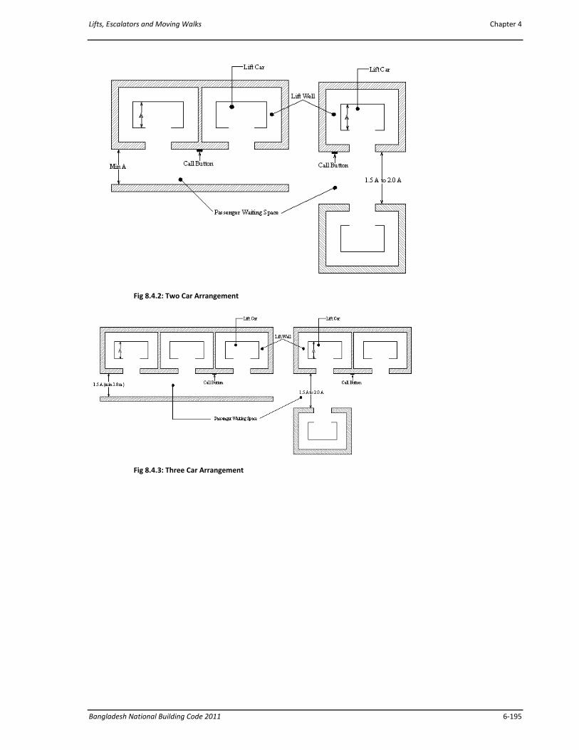
Lifts, Escalators and Moving Walks Chapter 4
Bangladesh National Building Code 2011 6‐195
Fig 8.4.2: Two Car Arrangement
Fig 8.4.3: Three Car Arrangement
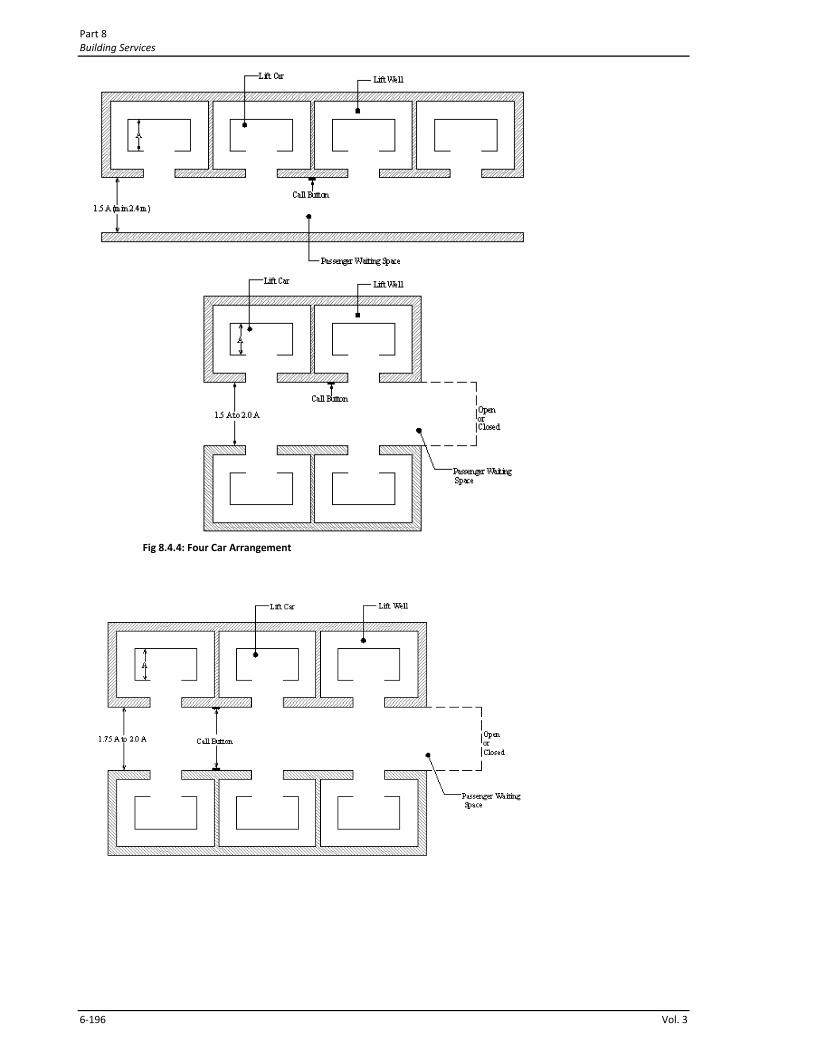
Part 8 Building Services
6‐196 Vol. 3
Fig 8.4.4: Four Car Arrangement

Lifts, Escalators and Moving Walks Chapter 4
Bangladesh National Building Code 2011 6‐197
Fig 8.4.5: Six Car Arrangement
Fig 8.4.6: Eight Car Arrangement
4.3.4.2
If a machine room on the lift well is impracticable for architectural or other reasons, the machine room may be placed below the lift well or in the basement, keeping adequate safety provisions. If the lift machine room is located in the basement, it shall be separated from the lift well by a separation wall. Alternatively, machine room less lift can be considered for installation.
4.3.4.3
High speed lifts with gearless machine shall, in all cases, have machine room above the lift well.
4.3.4.4
Machine room shall not be located adjacent to or above sleeping rooms (bed rooms) in residential and hotel buildings; and patients' rooms, intensive care rooms and operation theatres of hospital/health care buildings.
Part 8 Building Services
6‐198 Vol. 3
4.3.5 Structural Considerations
4.3.5.1
Lift well enclosures, lift pits, machine rooms and machine supports, besides conforming to the essential requirements in Sec 4.2, shall form part of the building construction and comply with the lift manufacturer's drawings.
4.3.5.2 Machine Room
Machine room floor shall be strong enough to support the heaviest component of lift machinery and shall be designed to carry a load of not less than 500 kg/m2 over the whole area and also any load which may be imposed thereon by the equipment used in the machine room or by any reaction from any such equipment during periods of both normal operation and repair .
4.3.5.3
The total load on overhead beams and their supporting structural members shall be assumed to be equal to the dead load of slabs including load of all equipment resting on the beams plus twice the minimum load suspended from the beams.
4.3.5.4
The deflection of the overhead beams under the minimum static load calculated in accordance with Sec 4.3.5.3 shall not exceed
11500 of the span.
4.3.5.5
Beams at all other floor slabs which correspond to the beam at machine room floor shall also be made stronger to take the reaction from the guides when the lift is made to stop consequent to the breaking of the wire ropes or the application of the safety device.
4.3.5.6
Suitable lifting beams may be provided immediately below the machine room ceiling for carrying the tackle to facilitate lifting of any heavy part of a heavy lift. For lower capacity lifts, suitable suspension hooks may be provided.
4.3.5.7
The roof of the machine room shall be strong enough to take up the pulley which could be used for lifting up parts of the lift machinery for inspection and repair.
4.3.5.8
The equivalent dead loads imposed upon the building by the lift installations shall be shown on the lift manufacturer's drawing so that the architect/engineer may make provisions accordingly.
4.3.6 Control System
4.3.6.1
The control of operation of the lift system, leveling, door opening and closing, response to hall calls etc. shall be fully automatic. All control equipment shall be efficient and fail‐safe.
4.3.6.2
The control system shall be capable of accelerating the car smoothly to full running speed and stopping the lift with smooth retardation.
4.3.6.3
Variation in speed of the lift between no load and full load conditions shall not be more than plus or minus five per cent. The control system shall be capable of correcting any tendency to overspeed or underspeed. The control system shall have safety device(s) to stop the lift car if its running speed exceeds its rated speed by ten per cent.
Lifts, Escalators and Moving Walks Chapter 4
Bangladesh National Building Code 2011 6‐199
4.3.6.4
It shall have facility to level or re‐level the lift car within plus or minus 13 mm. The leveling system shall be fully automatic and shall correct for over travel or under travel and rope stretch. The car stopping and leveling system shall be unaffected by external influences like variation in load, temperature, rope elongation etc.
4.3.6.5
Closing and opening of car doors and landing doors shall be fully automatic and shall operate in full synchronization with one another. Door opening and closing operations shall be so controlled as to ensure proper safety of passengers.
4.3.6.6
Door opening and closing time and door hold open time shall be automatically controlled to get minimum transfer time in any landing. For larger installations, transfer times shall be independently adjustable to suit the requirements of the building as well as the characteristics of the traffic.
4.3.6.7
Independent door closing push button shall be provided in the lift car to allow instant door closing. Similarly door opening push button shall be provided in the lift car to reverse the closing motion of the doors or hold them open.
4.3.6.8
When there are conditions that particularly affect the safety of passengers, the closing of doors shall only be effected by the continuous pressure of push buttons in the lift car or landings.
4.3.6.9
Each lift shall have key operated switch to transfer from normal passenger control to a car preference control. During car preference control the operation of the lift shall be from the car only and the doors shall remain open until a car call is registered for a floor designation. All landing calls shall be bypassed and car position indicators on the landings for this lift shall not be illuminated.
4.3.6.10
Provisions shall be made in the control system to take any car out of service still maintaining the controlled operation of the remaining cars of a group of cars required for passenger traffic. It is essential that such provision shall not stop the fireman's control from being operative in the event of the lift being designated as a fireman's lift.
4.3.6.11
When required, fire switch shall be provided in the control system as per Sec 4.2.2.2.
4.4 ESCALATORS
4.4.1 General
4.4.1.1
Escalators shall be located in the main line of circulation and in such a way that most persons entering the building can see it. Care shall be taken to eliminate interference to the traffic movement.
4.4.1.2
Escalators shall discharge into an open area with no turns or choice of direction necessary. Ample space for people must be provided at the entry and exit landings of an escalator, space between the newel and the nearest obstruction in front of the escalator shall be a minimum of 3 m.
4.4.1.3
Part 8 Building Services
6‐200 Vol. 3
If an unloading area is restricted, such restrictions as doors or gates shall be interlocked with the escalator to insure that the restriction is removed before the escalator can be run.
4.4.1.4
The escalator shall have provision to run in both upward and downward directions. However it shall not run in one direction for one trip and reversed for the next. Starting, stopping or reversal shall be controlled only by an attendant and with the assurance that no passenger is riding at that time.
4.4.1.5
Minimum head room above the escalator (minimum vertical clearance between the line of step nosing and lowest edge of ceiling opening) shall not be less than 2.3 m.
4.4.1.6
Near the place of escalator installation, one lift with wheel chair facility shall be installed to facilitate vertical movement of disabled persons.
4.4.2 Essential Requirements
4.4.2.1
Angle of incline of the escalator shall not be more than 30⁰ from the horizontal. In particular cases, an angle of incline up to 35o may be permitted for escalators having a vertical rise not more than 6 m.
4.4.2.2
The speed of the escalator, measured along the incline shall not be more than 0.63 m/s for 30o angle of incline and 0.50 m/s for 35o angle of incline.
4.4.2.3 Balustrades
(a) Escalators shall be provided on each side with solid balustrades. On the step side (interior panel), the balustrades shall be smooth and substantially flush except for protective molding parallel to the run of the steps. Vertical moldings that cover joints of panels shall be properly bevelled and shall not project more than 6.5 mm. Gaps between interior panels of the balustrade shall not be wider than 4mm.
(b) The width between balustrades, measured on the incline up to a point 680 mm vertically above the nose line of the steps, shall not be less than the width of the step. It shall not exceed the width of the step by more than 330 mm with a maximum of 165 mm on either side of the escalator.
(c) There shall be no abrupt changes in the width between the balustrades on the two sides of the escalator. Where a change in width is unavoidable, such change shall not exceed 8 per cent of the greater width. In changing the direction of the balustrades resulting from a reduction in width the maximum allowable angle of change in balustrades shall not exceed 15 degrees from the line of the escalator travel.
(d) The balustrade interior paneling shall have adequate mechanical strength and rigidity. When a force of 500 N is applied at an angles on gap greater than 4 mm and no permanent deformation.
(e) The use of glass for balustrade interior panelling is permitted, provided it is splinter free one layer safety (tempered) glass and has sufficient mechanical strength and rigidity. The thickness of the glass shall not be less than 6 mm.
4.4.2.4
The clearance on either side of the steps between the steps and the adjacent skirt guard shall not be more than 5 mm and the sum of the clearances on both sides shall not be more than 6 mm.
4.4.2.5
Where the intersection of the outside balustrade (deck board) and the ceiling or soffit is less than 600 mm from the centre line of the handrail, a solid guard shall be provided in the intersecting angle of the outside balustrade
Lifts, Escalators and Moving Walks Chapter 4
Bangladesh National Building Code 2011 6‐201
(deck board) and the ceiling or soffit. The vertical face of the guard shall project at least 360 mm horizontally from the apex of the angle.
4.4.2.6 Handrails
(a) Each balustrade shall be provided with a handrail moving in the same direction and at the same speed as the steps.
(b) Each moving handrail shall extend at normal handrail height not less than 300 mm beyond the line of points of comb plate teeth at the upper and lower landings.
(c) Hand or finger guards shall be provided at points where the handrails enter the balustrade. (d) The horizontal distance between the centre lines of two handrails, measured on the incline, shall not
exceed the width between the balustrades by more than 150 mm, with a maximum of 75 mm on either side of the escalator.
4.4.2.7 Step Treads
(a) The depth of any step tread in the direction of travel shall not be less than 400 mm and the rise between treads shall not be more than 220 mm.
(b) The maximum clearance between step treads on the horizontal run shall be 4 mm.
(c) The tread surface of each step shall be slotted in a direction parallel to the travel of the steps. Each slot shall not be more than 6.5 mm wide and not be less than 9.5 mm deep; and the distance from centre to centre of adjoining slots shall not be more than 9.5 mm.
(d) Safety provision shall be installed in the system to stop the escalator when anything is stuck in the clearance between the step tread and the skirting.
4.4.2.8 Landings
Landings shall be made of anti‐slip material.
4.4.2.9 Comb Plates
There shall be comb plates at the upper and lower landings of every escalator. The comb plate teeth shall be meshed with and set into the slots of the tread surface. Comb plates shall be adjustable vertically. Safety provision shall be installed in the comb plate assembly so that the safety contact stops the escalator when anything is caught between the comb plate and the step.
4.4.2.10 Trusses
The truss shall be designed to sustain the dead and live loads of the steps and running gear in operation safely. In the event of failure of the track system it shall retain the running gear in its guides.
4.4.2.11 Step Wheel Tracks
These shall be designed to prevent displacement of steps and running gear if a step chain breaks.
4.4.2.12 Rated Load
The escalator shall be selected in such a way that it does not exceed its rated load during operation.
The rated load in kilogram on an escalator shall be computed by the following formula :
Rated load = 0.27 W A kg
where,
W = width between the balustrades, mm ; and
A = horizontal distance between the upper and lower comb plate teeth , (m).
4.4.2.13 Design Factor of Safety
The factor of safety based on static load shall be at least the following :
i. for trusses and all structural members including tracks 5
ii. for driving machine parts :
a) where made of steel or bronze 8
Part 8 Building Services
6‐202 Vol. 3
b) where made of cast iron and other materials 10
iii. for power‐transmission members 10
Step chain composed of cast‐steel links which, if thoroughly annealed, shall be permitted with a factor of safety of at least 20.
4.4.2.14 Driving Machine, Motor and Brake
(a) The driving machine shall be connected to the main drive shaft by toothed gearing, a coupling, or a chain.
(b) An electric motor shall not drive more than one escalator.
(c) Each escalator shall be provided with an electrically released, mechanically applied brake capable of stopping the up or down travelling escalator with any load up to the rated load. The brake shall be located either on the driving machine or on the main drive shaft.
Where a chain is used to connect the driving machine to the main drive shaft, a brake shall be provided on this shaft. It is not required that this brake be of the electrically released type if an electrically released brake is provided on the driving machine.
(d) The braking system shall have provision to bring the escalator automatically to a smooth stop in the event of failure of electrical power or mechanical parts.
(e) Speed Governor : A speed governor shall be provided, the operation of which shall automatically shut down the escalator in case of over speed or under speed, and prevent reversal of direction (up or down).
(f) Adequate illumination shall be provided at all landings, at the comb plates and completely down all stair ways.
(g) An emergency stop switch shall be located near the comb plate or in some obtrusive location.
(h) All machinery spaces shall have access doors or panels for inspection and maintenance. These panels shall remain locked to prevent unauthorized access.
(i) Reasonable ventilation shall be provided in machinery spaces.
4.4.2.15 Escalator Capacity
(a) For normal peak period, the recommended handling capacity for design purposes shall be taken as 3200 to 6400 persons per hour depending upon the width of the escalator.
(b) The number of persons that may be theoretically carried by the escalator in 1 hour can be calculated as follows :
i. For determination of theoretical capacity it Is assumed that one step with an average depth of 0.4 m can carry 1 person for step width of 0.6m, 1.5 persons for a step width of 0.8m and two persons for step width of 1m.
ii. The theoretical capacity = 3600 x( v x k)/0.4
where,
v = rated speed of escalator in m/s
k = 1, 1.5 or 2 for step width of 0.6m, 0.8m and 1m respectively.
4.5 MOVING WALKS
4.5.1 Essential Requirements
4.5.1.1
Angle of incline of moving walks shall be no more than 15o. A moving walk may have sloping entrance and exit or level entrance and exit.
4.5.1.2
The operating speeds of moving walk at different inclinations and different entrance and exit conditions shall not be more than those given in Table 8.4.6

Lifts, Escalators and Moving Walks Chapter 4
Bangladesh National Building Code 2011 6‐203
Table 8.4.6 Operating Speeds of Moving Walk (Based on 1000 mm Nominal Tread Width)*
Incline of Ramp on Slope Maximum Speed with Level
Entrance and Exit
(m/s)
Maximum Speed with Sloping
Entrance and Exit
(m/s)
0 to 3o
0.9
0.9
Over 3 to 5o 0.9 0.8
Over 5 to 8o 0.9 0.7
Over 8 to 12o 0.7 0.65
Over 12 to 15o 0.7 0.63
* Higher tread width may be allowable on horizontal runs.
4.5.2 Balustrades
(a) Moving walks shall be provided on each side with solid balustrades. On the tread way side the balustrades shall be smooth and substantially flush.
(b) The width between balustrades, measured up to a point 680 mm vertically above the tread way, shall not be less than the width of the tread way. It shall not exceed the width of the tread way by more than 330 mm with a maximum of 165 mm on either side of the moving walk.
(c) There shall be no abrupt changes in width between the balustrades on the two sides of the moving walk. Where a change in width is unavoidable, such change shall not exceed 8 per cent of the greater width. In changing the direction of the balustrades resulting from a reduction in width the maximum allowable angle of change in balustrades shall not exceed 15 degrees from the line of the moving walk travel.
4.5.3 Handrails
4.5.3.1
Each balustrade shall be provided with a handrail moving in the same direction and at the same speed as the tread way. Only one handrail may be allowed in a moving walk when the slope of the walkway does not exceed 3o, operating speed is less than 0.35 m/s or the width is no more than 530 mm.
4.5.3.2
Each moving handrail shall extend at normal handrail height not less than 300 mm beyond the line of points of comb plate teeth at the upper and lower landings.
4.5.3.3
Hand or finger guards shall be provided at the point where the handrails enter the balustrade.
4.5.3.4
The horizontal distance between the centre lines of two handrails shall not exceed the width between the balustrades by more than 150 mm with a maximum of 75 mm on either side of the moving walk.
4.5.4 Tread Way
4.5.4.1
The tread surface of the tread way shall be slotted in a direction parallel to the direction of travel.
4.5.4.2
The clearance on either side of the tread way between the tread way and the adjacent skirt guard shall not be more than 5 mm and the sum of the clearances on both sides shall not be more than 6 mm. Safety provisions shall be kept in the system to stop the moving walk when anything is stuck in the clearance between the tread way and the adjacent skirt guard.
Part 8 Building Services
6‐204 Vol. 3
4.5.5 Landings
Landings shall be made of anti‐slip material.
4.5.6 Comb Plates
4.5.6.1
There shall be comb plates at the entrance and exit of each moving walk. The comb plate teeth shall be meshed with and set into the slots in the tread surface. Safety provision shall be installed in the comb plate assembly so that the safety contact stops the moving walk when anything is caught between the comb plate and the tread.
4.5.6.2
An emergency stop switch shall be located near the comb plate or at some obtrusive location.
4.5.6.3
Adequate illumination shall be provided at comb plates.
4.6 INSPECTION AND CERTIFICATION
4.6.1
All new lifts, escalators and moving walks, after installation, shall be inspected and tested by the Authority before these are put into normal services.
These shall not be brought into use unless the Authority is satisfied that the installations have been carried out as per provisions of this Code and tests indicate that all the safety devices operate satisfactorily. It shall be unlawful to operate any lift, escalator or moving walk without a current certificate of inspection issued by the Authority. Certificates shall not be issued when the conveyance is posted as unsafe pursuant to Sec 4.6.7.
4.6.2
All electrical lines, control lines and earthings of lift, escalator and moving walk systems shall be tested to determine whether these have been installed properly to meet the requirements of the machine and as per provisions of Chapter 1.
4.6.3 Testing
Tests shall be carried out to determine the operational and safety conditions of lifts, escalators and moving walks in accordance with the provisions of section :
4.6.3.1 Lift
Tests shall be conducted to ascertain that
(a) the motor, brake control equipment and car leveling mechanism function properly,
(b) the door operation is proper and door locking devices function properly, (c) the car raises and lowers rated load, (d) the car achieves at least the rated speed, (e) the lift motor can be overloaded up to a minimum of 10% above the rated capacity,
(f) the safety gear stops the car with the rated load in case of over speed and/or over travel etc.,
(g) the buffers function properly, and (h) the safety gear operate and keeps operation of the lift suspended in case of the lift car is loaded
above its maximum capacity.
4.6.3.2 Escalator and Moving Walk
Tests on escalators and moving walks shall be conducted to ascertain that
(a) the automatic control device functions properly and brings the escalator to a smooth stop in case of failure of any mechanical parts or electrical power,
Lifts, Escalators and Moving Walks Chapter 4
Bangladesh National Building Code 2011 6‐205
(b) the automatic safety protection for over speed, under speed and direction reversal functions properly, and
(c) Safety devices function properly and stops the escalator or moving walk when anything is caught between the comb plate and the treads or the skirting and the treads.
(d) the handrail and steps or tread way travel at exactly the same speed.
4.6.4
A lift, escalator or moving walk, in which repair and/or maintenance work has been carried out shall also be put to the relevant tests as provided for in Sec 4.6.3.
4.6.5
After proper testing, the Authority shall issue certificate regarding suitability of the lift, escalator or moving walk for normal or regular service. A lift, escalator or moving walk shall be allowed to work only on issuance of this certificate.
4.6.6
The lift, escalator or moving walk shall be inspected periodically to ensure safety.
4.6.7
When an inspection reveals an unsafe condition and the Authority finds that the unsafe condition endangers human life, the Authority shall cause to be placed on such lift, escalator or moving walk, in a conspicuous place, a notice stating that such conveyance is unsafe. The owner shall see to it that such notice of unsafe condition is legibly maintained where placed by the Authority. The Authority shall also issue an order in writing to the owner requiring the repairs or alterations to be made to such conveyance which are necessary to render it safe and may order the operation thereof discontinued until the repairs or alterations are made or the unsafe conditions are removed. A posted notice of unsafe conditions shall be removed only by the Authority and when satisfied that the unsafe conditions have been corrected.
4.7 OPERATION AND MAINTENANCE
4.7.1
The owner shall be responsible for the safe operation and maintenance of each lift, escalator or moving walk installation and shall cause periodic inspections, tests and maintenance to be made on such conveyances as required in this section.
4.7.2
The lift, escalator or moving walk shall receive regular cleaning and lubrication of relevant parts, and adjustment and adequate servicing by authorized competent persons at such intervals as the type of equipment and frequency of service demand. In order that the lift, escalator or moving walk installation is maintained at all times in a safe condition, a proper maintenance schedule shall be drawn up in consultation with the machine manufacturer which shall be strictly followed.
4.7.3
In case of lift, periodic examination of wire ropes, components of landing and car doors, door interlocking mechanism, brakes, gears, components of safety gears, guides, rollers, channels etc. shall be carried out as recommended by the manufacturer. In no case shall the interval between such inspections exceed six months.
4.7.4
Grooves of drums, sheaves and pulleys of lifts shall also be examined when rope replacement is made. If necessary, the drums, sheaves or pulleys shall be properly remachined.
Part 8 Building Services
6‐206 Vol. 3
4.7.5
In case of escalators and moving walks, periodic examination of balustrades, handrail, tread way, tread way interconnection, comb plates speed governor, drives, chains, non‐reversal device, brakes, gears etc. shall be carried out as recommended by the manufacturer, but in no case the interval shall exceed six months.
4.7.6 Sundry Precautions
4.7.6.1
Adequate precaution shall be taken to guard against any possibility of a lift being operated by unauthorized persons. Precautions shall also be taken to prevent a lift from being operated by any person when it is not intended for use.
4.7.6.2
No person shall remain in the pit while the lift is working. Adequate precautions shall be taken to protect persons working in the pit from accidental contact with the counter weight.
4.7.6.3
While the lift is under examination or repairs, suitable steps shall be taken to ensure that the lift is not operated inadvertently by any person in such a manner as may endanger the safety of persons working in the lift.
4.7.6.4
No such explosive or other inflammable material shall be carried in the lift car as may endanger the safety of persons and property.
Related Appendix:‐
Appendix 8‐4‐A: Format for Particulars of Lifts, Escalators and Moving Walks