Embed Size (px)
Citation preview
Lightweight and Cost Efficient Spaceborn Patch Antenna
Korbinian Schraml, Ralf Wilke, Dirk Heberling Institute of High Frequency Technology
RWTH Aachen University Aachen, Germany
{Schraml, Wilke, Heberling}@ihf.rwth-aachen.de
Adam Narbudowicz Antenna & High Frequency Research Centre
Dublin Institute of Technology Dublin, Ireland
line 4: e-mail address if desired
Abstract—In order to achieve lightweight yet low cost antennas for use in a geostationary space environment, the GeReLEO-SMART project develops a substrate-based, multilayer antenna structure which can replace traditional horn antennas as feeds for reflector antennas. To verify a design, an example mission is developed, consisting of a 2x2 patch antenna array with an integrated stripline bandpass filter. The operation frequency is 25.935 GHz. This multilayer antenna will be tested on board of the German technology demonstration mission “Heinrich-Hertz” (H2SAT). The design passed all tests for space qualification without decrease in performance.
I. INTRODUCTION
Traditionally the feed of large reflector antennas for satellite communications were metal based structures, such as horn antennas [1]. The solution will be tested on the German technology demonstration mission "Heinrich-Hertz" (H2SAT) in a geostationary orbit. Those solutions have a disadvantage of high weight, manufacturing costs and occupy a huge volume. On the other hand patch antennas could resolve those issues, as they are known for their low-cost, lightweight and low profile. Unfortunately due to dielectrical substrates most terrestrial antennas cannot withstand the space environment, e.g. radiation, thermal changes and vibration during launch. [2] The proposed paper assesses space capabilities of patch antennas by designing a 2x2 array on a standard RTduroid 6002 material. The proposed antenna is designed for a geostationary relais-station for low-earth-orbit-satellite-to-earth communication. Special focus of this project is the technology verification of the structure in the tough environment during the launch and commissioning of the satellite and the experimental investigation of degradation over the operation time. The successful mission will provide information about the long time performance of substrate based antennas in space.
II. DESIGN
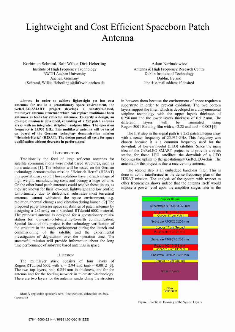
The multilayer stack consists of four layers of Rogers RTduroid 6002 with εr = 2.94 and tanδ = 0.0012 [3]. The two top layers, both 0.254 mm in thickness, are for the antenna and for the feeding network in microstrip-technology. There are two layers for the antenna sandwiching the structure
in between them because the environment of space requires a superstrate in order to prevent oxidation. The two bottom layers support the filter, which is developed in a unsymmetrical stripline technology with the upper layer's thickness of 0.256 mm and the lower layer's thickness of 0.512 mm. The different layers will be laminated using Rogers 3001 Bonding film with εr =2.28 and tanδ = 0.003 [4]
The first step in the signal path is a 2x2 patch antenna array with a center frequency of 25.935 GHz. This frequency was chosen because it is a common frequency used for the downlink of low-earth-orbit (LEO) satellites. Since the main idea of the GeReLEO-SMART project is to provide a relais station for those LEO satellites, the downlink of a LEO becomes the uplink to the geostationary GeReLEO-relais. The antenna for this project is thus a receive-only antenna.
The second step is an embedded bandpass filter. This is done to avoid interference in the dense frequency plan of the H2SAT mission. The analysis of the system with respect to other frequencies shows indeed that the antenna itself would impose a power level upon the amplifier stages later in the
Identify applicable sponsor/s here. If no sponsors, delete this text box. (sponsors)
Figure 1. Sectional Drawing of the System Layers
978-1-5090-2214-4/16/$31.00 ©2016 IEEE
signal path, which is high enough to drive the amplifiers into saturation. To attenuate the undesired frequencies a bandpass filter is needed.
III. DESIGN OF THE 2X2 PATCH ANTENNA ARRAY
The antenna in the GeReLEO-SMART project is a 2x2 patch antenna array with a center frequency of 25.935 GHz and a Left Hand Circular Polarization (LHCP). On top of this patch there is the already mentioned superstrate. The first design was done according to [5], later the simulation tool CST Microwave Studio was used to fine tune the antenna's performance. The antenna is shown in Figure 4.
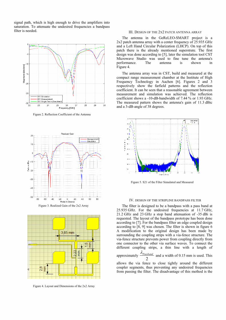
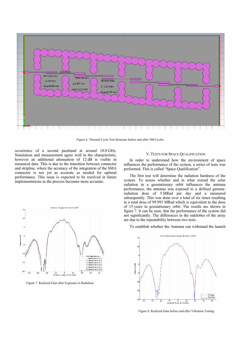
The antenna array was in CST, build and measured at the compact range measurement chamber at the Institute of High Frequency Technology in Aachen [6]. Figures 2 and 3 respectively show the farfield patterns and the reflection coefficient. It can be seen that a reasonable agreement between measurement and simulation was achieved. The reflection coefficient shows a -10-dB-bandwidth of 7.44 % or 1.93 GHz. The measured pattern shows the antenna's gain of 11.3 dBic and a 3-dB-angle of 38 degrees.
IV. DESIGN OF THE STRIPLINE BANDPASS FILTER
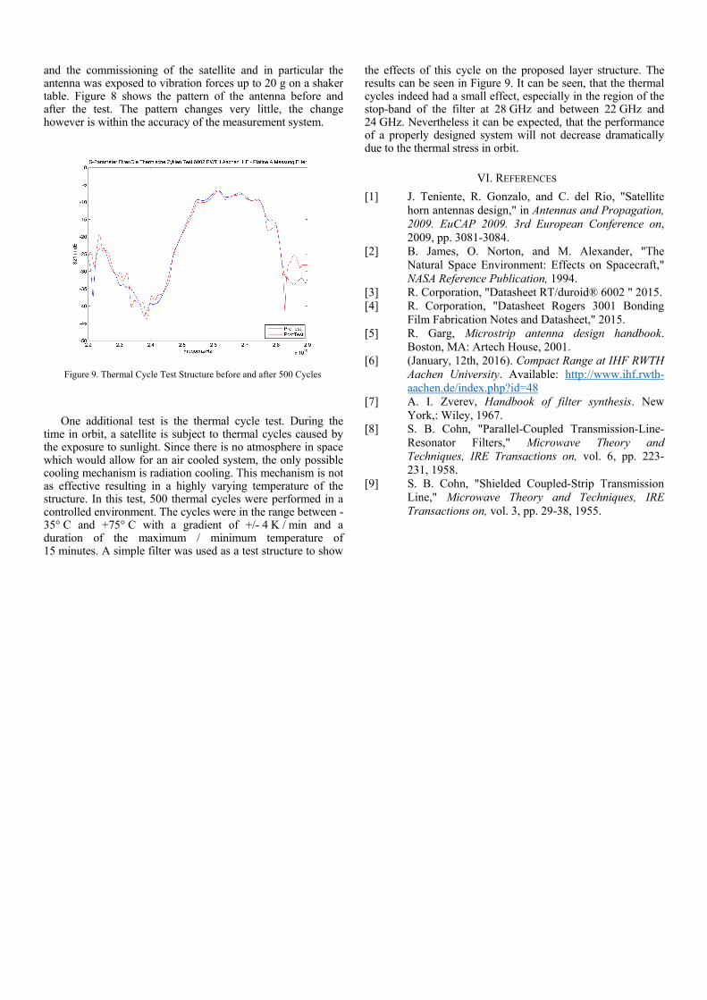
The filter is designed to be a bandpass with a pass band at 25.935 GHz. For the undesired frequencies at 11.7 GHz, 21.2 GHz and 23 GHz a stop band attenuation of -35 dBi is requested. The layout of the bandpass prototype has been done according to [7]. For the bandpass filter an edge coupled design according to [8, 9] was chosen. The filter is shown in figure 6 A modification to the original design has been made by surrounding the coupling strips with a via-fence structure. The via-fence structure prevents power from coupling directly from one connector to the other via surface waves. To connect the different coupling strips, a thin line with a length of
approximately 2
Passband and a width of 0.15 mm is used. This
allows the via fence to close tightly around the different coupler segments, thus preventing any undesired frequencies from passing the filter. The disadvantage of this method is the
Figure 2. Reflection Coefficient of the Antenna
Figure 5. S21 of the Filter Simulated and Measured
Figure 3. Realized Gain of the 2x2 Array
Figure 4. Layout and Dimensions of the 2x2 Array
occurrence of a second passband at around 10.8 GHz. Simulation and measurement agree well in the characteristic, however an additional attenuation of 12 dB is visible in measured data. This is due to the transition between connector and stripline, where the accuracy of the integration of the SMA connector is not yet as accurate as needed for optimal performance. This issue is expected to be resolved in future implementations as the process becomes more accurate.
V. TESTS FOR SPACE QUALIFICATION
In order to understand how the environment of space influences the performance of the system, a series of tests was performed. This is called “Space Qualification”.
The first test will determine the radiation hardness of the system. To assess whether and in what extend the solar radiation in a geostationary orbit influences the antenna performance, the antenna was exposed to a defined gamma-radiation dose of 5 MRad per day and a measured subsequently. This was done over a total of six times resulting in a total dose of 99.993 MRad which is equivalent to the dose of 15 years in geostationary orbit. The results are shown in figure 7. It can be seen, that the performance of the system did not significantly. The differences in the sidelobes of the array are due to the repeatability between two tests.
To establish whether the Antenna can withstand the launch
Figure 7. Realized Gain after Exposure to Radiation
Figure 8. Realized Gain before and after Vibration Testing
Figure 6. Thermal Cycle Test Structure before and after 500 Cycles
and the commissioning of the satellite and in particular the antenna was exposed to vibration forces up to 20 g on a shaker table. Figure 8 shows the pattern of the antenna before and after the test. The pattern changes very little, the change however is within the accuracy of the measurement system.
One additional test is the thermal cycle test. During the time in orbit, a satellite is subject to thermal cycles caused by the exposure to sunlight. Since there is no atmosphere in space which would allow for an air cooled system, the only possible cooling mechanism is radiation cooling. This mechanism is not as effective resulting in a highly varying temperature of the structure. In this test, 500 thermal cycles were performed in a controlled environment. The cycles were in the range between -35° C and +75° C with a gradient of +/- 4 K / min and a duration of the maximum / minimum temperature of 15 minutes. A simple filter was used as a test structure to show
the effects of this cycle on the proposed layer structure. The results can be seen in Figure 9. It can be seen, that the thermal cycles indeed had a small effect, especially in the region of the stop-band of the filter at 28 GHz and between 22 GHz and 24 GHz. Nevertheless it can be expected, that the performance of a properly designed system will not decrease dramatically due to the thermal stress in orbit.
VI. REFERENCES
[1] J. Teniente, R. Gonzalo, and C. del Rio, "Satellite horn antennas design," in Antennas and Propagation, 2009. EuCAP 2009. 3rd European Conference on, 2009, pp. 3081-3084.
[2] B. James, O. Norton, and M. Alexander, "The Natural Space Environment: Effects on Spacecraft," NASA Reference Publication, 1994.
[3] R. Corporation, "Datasheet RT/duroid® 6002 " 2015. [4] R. Corporation, "Datasheet Rogers 3001 Bonding
Film Fabrication Notes and Datasheet," 2015. [5] R. Garg, Microstrip antenna design handbook.
Boston, MA: Artech House, 2001. [6] (January, 12th, 2016). Compact Range at IHF RWTH
Aachen University. Available: http://www.ihf.rwth-aachen.de/index.php?id=48
[7] A. I. Zverev, Handbook of filter synthesis. New York,: Wiley, 1967.
[8] S. B. Cohn, "Parallel-Coupled Transmission-Line-Resonator Filters," Microwave Theory and Techniques, IRE Transactions on, vol. 6, pp. 223-231, 1958.
[9] S. B. Cohn, "Shielded Coupled-Strip Transmission Line," Microwave Theory and Techniques, IRE Transactions on, vol. 3, pp. 29-38, 1955.
Figure 9. Thermal Cycle Test Structure before and after 500 Cycles