Embed Size (px)
Citation preview
Test Report No. 12069.1 No. of Pages 21
Lightweight Shock and Type I Vibration Test Report on
UPS Model No. PS3200RM for
Powerstar Inc. Gaithersburg, MD
NU LABORATORIES
312 Old Allerton Road, Annandale, NJ (908)713-9300
WWW.NULABS.COM E-Mail: [email protected]
25 February 2014
Prepared By Checked By Approved By Maria R. Valenta Ragen D. McAdoo R.D. McAdoo
25 February 2014
25 February 2014
25 February 2014
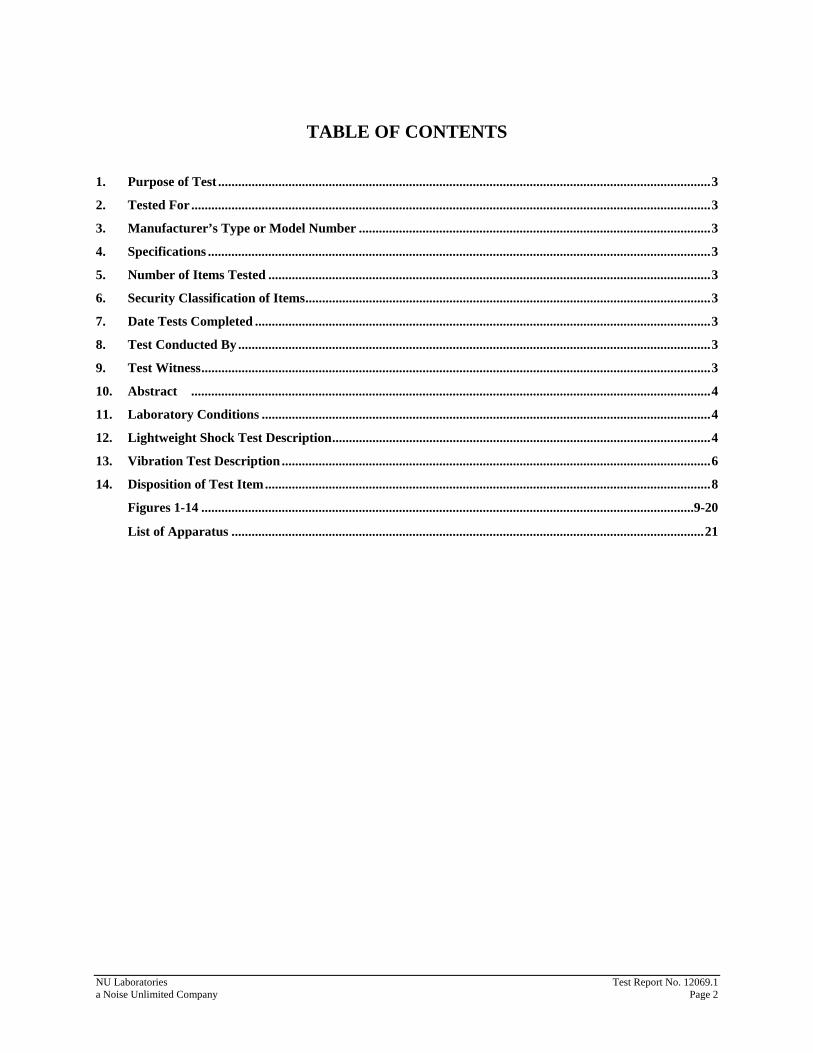
TABLE OF CONTENTS
1. Purpose of Test ...................................................................................................................................................3 2. Tested For ...........................................................................................................................................................3 3. Manufacturer’s Type or Model Number .........................................................................................................3 4. Specifications ......................................................................................................................................................3 5. Number of Items Tested ....................................................................................................................................3 6. Security Classification of Items.........................................................................................................................3 7. Date Tests Completed ........................................................................................................................................3 8. Test Conducted By .............................................................................................................................................3 9. Test Witness........................................................................................................................................................3 10. Abstract ...........................................................................................................................................................4 11. Laboratory Conditions ......................................................................................................................................4 12. Lightweight Shock Test Description.................................................................................................................4 13. Vibration Test Description ................................................................................................................................6 14. Disposition of Test Item.....................................................................................................................................8 Figures 1-14 ...................................................................................................................................................9-20
List of Apparatus .............................................................................................................................................21
NU Laboratories Test Report No. 12069.1 a Noise Unlimited Company Page 2
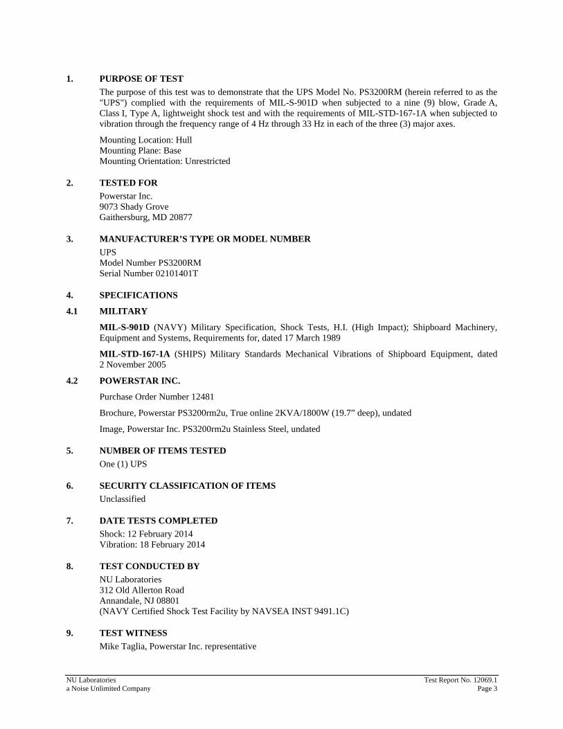
1. PURPOSE OF TEST The purpose of this test was to demonstrate that the UPS Model No. PS3200RM (herein referred to as the "UPS") complied with the requirements of MIL-S-901D when subjected to a nine (9) blow, Grade A, Class I, Type A, lightweight shock test and with the requirements of MIL-STD-167-1A when subjected to vibration through the frequency range of 4 Hz through 33 Hz in each of the three (3) major axes.
Mounting Location: Hull Mounting Plane: Base Mounting Orientation: Unrestricted
2. TESTED FOR Powerstar Inc. 9073 Shady Grove Gaithersburg, MD 20877
3. MANUFACTURER’S TYPE OR MODEL NUMBER UPS Model Number PS3200RM Serial Number 02101401T
4. SPECIFICATIONS
4.1 MILITARY
MIL-S-901D (NAVY) Military Specification, Shock Tests, H.I. (High Impact); Shipboard Machinery, Equipment and Systems, Requirements for, dated 17 March 1989
MIL-STD-167-1A (SHIPS) Military Standards Mechanical Vibrations of Shipboard Equipment, dated 2 November 2005
4.2 POWERSTAR INC.
Purchase Order Number 12481
Brochure, Powerstar PS3200rm2u, True online 2KVA/1800W (19.7” deep), undated
Image, Powerstar Inc. PS3200rm2u Stainless Steel, undated
5. NUMBER OF ITEMS TESTED One (1) UPS
6. SECURITY CLASSIFICATION OF ITEMS Unclassified
7. DATE TESTS COMPLETED Shock: 12 February 2014 Vibration: 18 February 2014
8. TEST CONDUCTED BY NU Laboratories 312 Old Allerton Road Annandale, NJ 08801 (NAVY Certified Shock Test Facility by NAVSEA INST 9491.1C)
9. TEST WITNESS Mike Taglia, Powerstar Inc. representative
NU Laboratories Test Report No. 12069.1 a Noise Unlimited Company Page 3
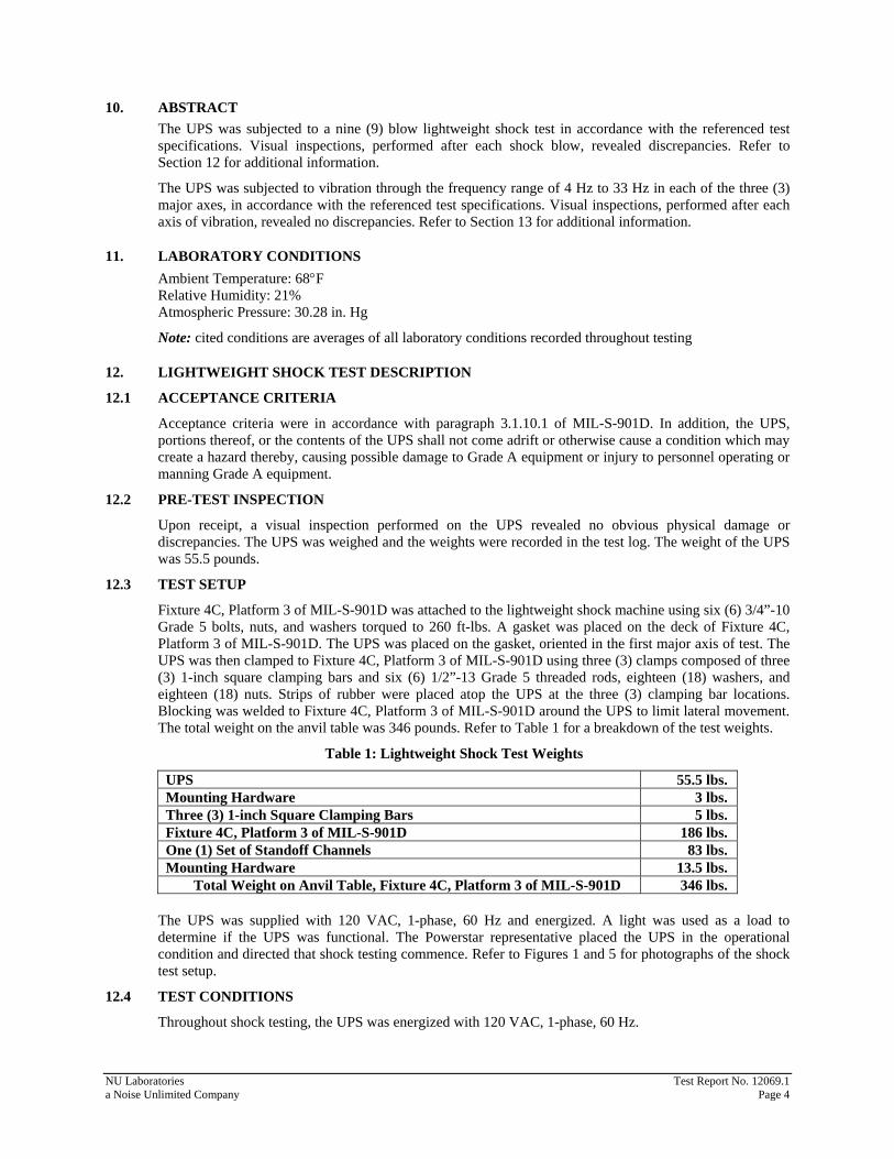
10. ABSTRACT The UPS was subjected to a nine (9) blow lightweight shock test in accordance with the referenced test specifications. Visual inspections, performed after each shock blow, revealed discrepancies. Refer to Section 12 for additional information.
The UPS was subjected to vibration through the frequency range of 4 Hz to 33 Hz in each of the three (3) major axes, in accordance with the referenced test specifications. Visual inspections, performed after each axis of vibration, revealed no discrepancies. Refer to Section 13 for additional information.
11. LABORATORY CONDITIONS Ambient Temperature: 68°F Relative Humidity: 21% Atmospheric Pressure: 30.28 in. Hg
Note: cited conditions are averages of all laboratory conditions recorded throughout testing
12. LIGHTWEIGHT SHOCK TEST DESCRIPTION
12.1 ACCEPTANCE CRITERIA
Acceptance criteria were in accordance with paragraph 3.1.10.1 of MIL-S-901D. In addition, the UPS, portions thereof, or the contents of the UPS shall not come adrift or otherwise cause a condition which may create a hazard thereby, causing possible damage to Grade A equipment or injury to personnel operating or manning Grade A equipment.
12.2 PRE-TEST INSPECTION
Upon receipt, a visual inspection performed on the UPS revealed no obvious physical damage or discrepancies. The UPS was weighed and the weights were recorded in the test log. The weight of the UPS was 55.5 pounds.
12.3 TEST SETUP
Fixture 4C, Platform 3 of MIL-S-901D was attached to the lightweight shock machine using six (6) 3/4”-10 Grade 5 bolts, nuts, and washers torqued to 260 ft-lbs. A gasket was placed on the deck of Fixture 4C, Platform 3 of MIL-S-901D. The UPS was placed on the gasket, oriented in the first major axis of test. The UPS was then clamped to Fixture 4C, Platform 3 of MIL-S-901D using three (3) clamps composed of three (3) 1-inch square clamping bars and six (6) 1/2”-13 Grade 5 threaded rods, eighteen (18) washers, and eighteen (18) nuts. Strips of rubber were placed atop the UPS at the three (3) clamping bar locations. Blocking was welded to Fixture 4C, Platform 3 of MIL-S-901D around the UPS to limit lateral movement. The total weight on the anvil table was 346 pounds. Refer to Table 1 for a breakdown of the test weights.
Table 1: Lightweight Shock Test Weights
UPS 55.5 lbs. Mounting Hardware 3 lbs. Three (3) 1-inch Square Clamping Bars 5 lbs. Fixture 4C, Platform 3 of MIL-S-901D 186 lbs. One (1) Set of Standoff Channels 83 lbs. Mounting Hardware 13.5 lbs. Total Weight on Anvil Table, Fixture 4C, Platform 3 of MIL-S-901D 346 lbs.
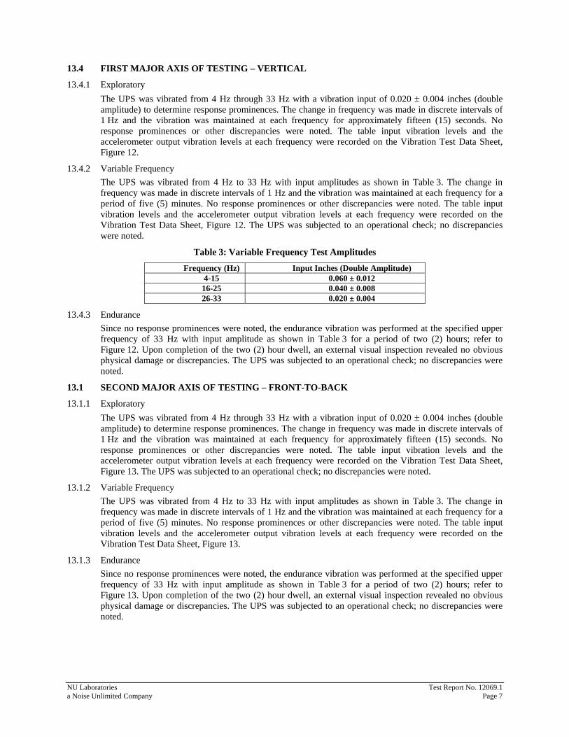
The UPS was supplied with 120 VAC, 1-phase, 60 Hz and energized. A light was used as a load to determine if the UPS was functional. The Powerstar representative placed the UPS in the operational condition and directed that shock testing commence. Refer to Figures 1 and 5 for photographs of the shock test setup.
12.4 TEST CONDITIONS
Throughout shock testing, the UPS was energized with 120 VAC, 1-phase, 60 Hz.
NU Laboratories Test Report No. 12069.1 a Noise Unlimited Company Page 4
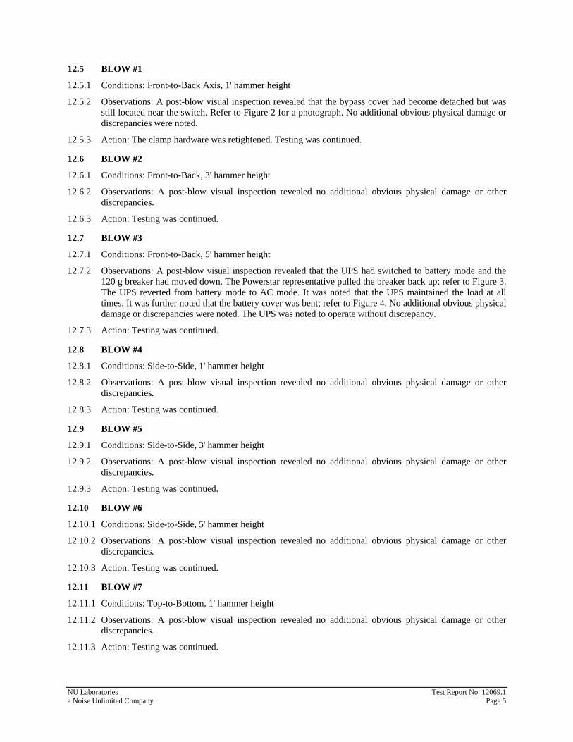
12.5 BLOW #1
12.5.1 Conditions: Front-to-Back Axis, 1' hammer height
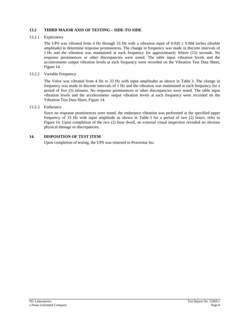
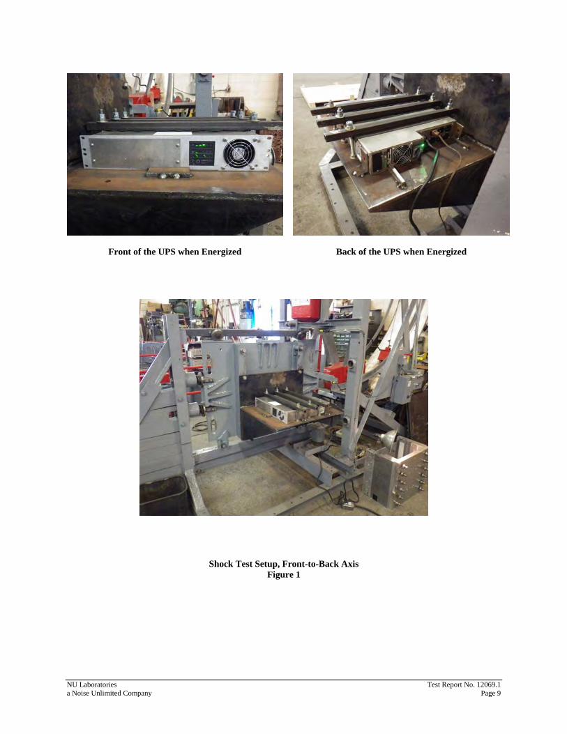
12.5.2 Observations: A post-blow visual inspection revealed that the bypass cover had become detached but was still located near the switch. Refer to Figure 2 for a photograph. No additional obvious physical damage or discrepancies were noted.
12.5.3 Action: The clamp hardware was retightened. Testing was continued.
12.6 BLOW #2
12.6.1 Conditions: Front-to-Back, 3' hammer height
12.6.2 Observations: A post-blow visual inspection revealed no additional obvious physical damage or other discrepancies.
12.6.3 Action: Testing was continued.
12.7 BLOW #3
12.7.1 Conditions: Front-to-Back, 5' hammer height
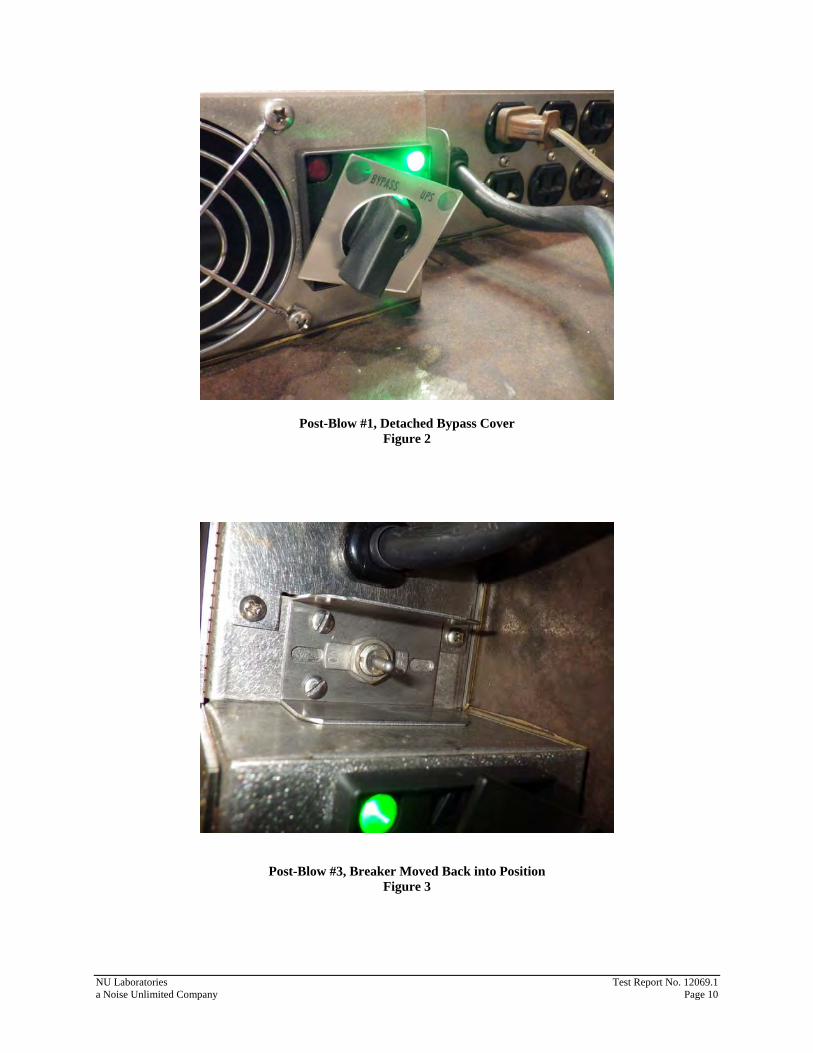
12.7.2 Observations: A post-blow visual inspection revealed that the UPS had switched to battery mode and the 120 g breaker had moved down. The Powerstar representative pulled the breaker back up; refer to Figure 3. The UPS reverted from battery mode to AC mode. It was noted that the UPS maintained the load at all times. It was further noted that the battery cover was bent; refer to Figure 4. No additional obvious physical damage or discrepancies were noted. The UPS was noted to operate without discrepancy.
12.7.3 Action: Testing was continued.
12.8 BLOW #4
12.8.1 Conditions: Side-to-Side, 1' hammer height
12.8.2 Observations: A post-blow visual inspection revealed no additional obvious physical damage or other discrepancies.
12.8.3 Action: Testing was continued.
12.9 BLOW #5
12.9.1 Conditions: Side-to-Side, 3' hammer height
12.9.2 Observations: A post-blow visual inspection revealed no additional obvious physical damage or other discrepancies.
12.9.3 Action: Testing was continued.
12.10 BLOW #6
12.10.1 Conditions: Side-to-Side, 5' hammer height
12.10.2 Observations: A post-blow visual inspection revealed no additional obvious physical damage or other discrepancies.
12.10.3 Action: Testing was continued.
12.11 BLOW #7
12.11.1 Conditions: Top-to-Bottom, 1' hammer height
12.11.2 Observations: A post-blow visual inspection revealed no additional obvious physical damage or other discrepancies.
12.11.3 Action: Testing was continued.
NU Laboratories Test Report No. 12069.1 a Noise Unlimited Company Page 5
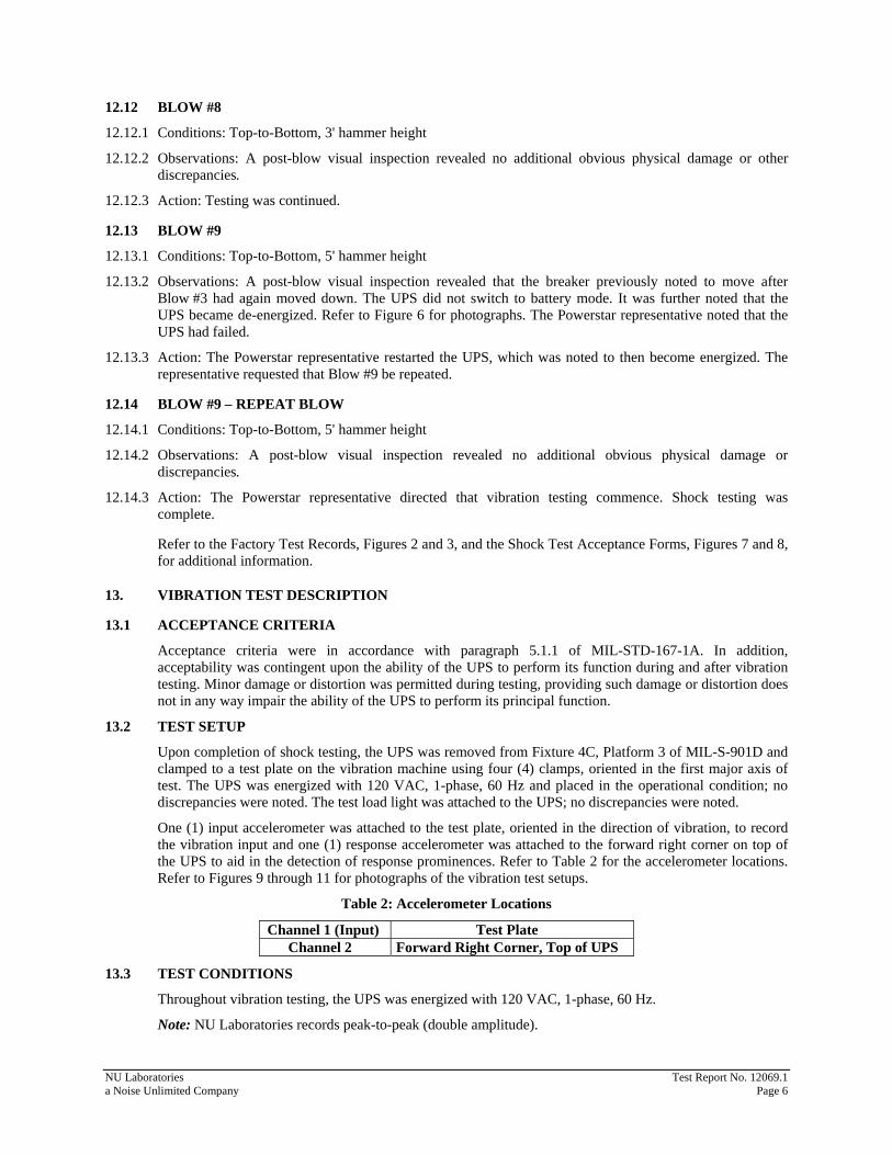
12.12 BLOW #8
12.12.1 Conditions: Top-to-Bottom, 3' hammer height
12.12.2 Observations: A post-blow visual inspection revealed no additional obvious physical damage or other discrepancies.
12.12.3 Action: Testing was continued.
12.13 BLOW #9
12.13.1 Conditions: Top-to-Bottom, 5' hammer height
12.13.2 Observations: A post-blow visual inspection revealed that the breaker previously noted to move after Blow #3 had again moved down. The UPS did not switch to battery mode. It was further noted that the UPS became de-energized. Refer to Figure 6 for photographs. The Powerstar representative noted that the UPS had failed.
12.13.3 Action: The Powerstar representative restarted the UPS, which was noted to then become energized. The representative requested that Blow #9 be repeated.
12.14 BLOW #9 – REPEAT BLOW
12.14.1 Conditions: Top-to-Bottom, 5' hammer height
12.14.2 Observations: A post-blow visual inspection revealed no additional obvious physical damage or discrepancies.
12.14.3 Action: The Powerstar representative directed that vibration testing commence. Shock testing was complete.
Refer to the Factory Test Records, Figures 2 and 3, and the Shock Test Acceptance Forms, Figures 7 and 8, for additional information.
13. VIBRATION TEST DESCRIPTION
13.1 ACCEPTANCE CRITERIA
Acceptance criteria were in accordance with paragraph 5.1.1 of MIL-STD-167-1A. In addition, acceptability was contingent upon the ability of the UPS to perform its function during and after vibration testing. Minor damage or distortion was permitted during testing, providing such damage or distortion does not in any way impair the ability of the UPS to perform its principal function.
13.2 TEST SETUP
Upon completion of shock testing, the UPS was removed from Fixture 4C, Platform 3 of MIL-S-901D and clamped to a test plate on the vibration machine using four (4) clamps, oriented in the first major axis of test. The UPS was energized with 120 VAC, 1-phase, 60 Hz and placed in the operational condition; no discrepancies were noted. The test load light was attached to the UPS; no discrepancies were noted.
One (1) input accelerometer was attached to the test plate, oriented in the direction of vibration, to record the vibration input and one (1) response accelerometer was attached to the forward right corner on top of the UPS to aid in the detection of response prominences. Refer to Table 2 for the accelerometer locations. Refer to Figures 9 through 11 for photographs of the vibration test setups.
Table 2: Accelerometer Locations
Channel 1 (Input) Test Plate Channel 2 Forward Right Corner, Top of UPS
13.3 TEST CONDITIONS
Throughout vibration testing, the UPS was energized with 120 VAC, 1-phase, 60 Hz.
Note: NU Laboratories records peak-to-peak (double amplitude).
NU Laboratories Test Report No. 12069.1 a Noise Unlimited Company Page 6
13.4 FIRST MAJOR AXIS OF TESTING – VERTICAL
13.4.1 Exploratory The UPS was vibrated from 4 Hz through 33 Hz with a vibration input of 0.020 ± 0.004 inches (double amplitude) to determine response prominences. The change in frequency was made in discrete intervals of 1 Hz and the vibration was maintained at each frequency for approximately fifteen (15) seconds. No response prominences or other discrepancies were noted. The table input vibration levels and the accelerometer output vibration levels at each frequency were recorded on the Vibration Test Data Sheet, Figure 12.
13.4.2 Variable Frequency The UPS was vibrated from 4 Hz to 33 Hz with input amplitudes as shown in Table 3. The change in frequency was made in discrete intervals of 1 Hz and the vibration was maintained at each frequency for a period of five (5) minutes. No response prominences or other discrepancies were noted. The table input vibration levels and the accelerometer output vibration levels at each frequency were recorded on the Vibration Test Data Sheet, Figure 12. The UPS was subjected to an operational check; no discrepancies were noted.
Table 3: Variable Frequency Test Amplitudes
Frequency (Hz) Input Inches (Double Amplitude) 4-15 0.060 ± 0.012 16-25 0.040 ± 0.008 26-33 0.020 ± 0.004
13.4.3 Endurance Since no response prominences were noted, the endurance vibration was performed at the specified upper frequency of 33 Hz with input amplitude as shown in Table 3 for a period of two (2) hours; refer to Figure 12. Upon completion of the two (2) hour dwell, an external visual inspection revealed no obvious physical damage or discrepancies. The UPS was subjected to an operational check; no discrepancies were noted.
13.1 SECOND MAJOR AXIS OF TESTING – FRONT-TO-BACK
13.1.1 Exploratory The UPS was vibrated from 4 Hz through 33 Hz with a vibration input of 0.020 ± 0.004 inches (double amplitude) to determine response prominences. The change in frequency was made in discrete intervals of 1 Hz and the vibration was maintained at each frequency for approximately fifteen (15) seconds. No response prominences or other discrepancies were noted. The table input vibration levels and the accelerometer output vibration levels at each frequency were recorded on the Vibration Test Data Sheet, Figure 13. The UPS was subjected to an operational check; no discrepancies were noted.
13.1.2 Variable Frequency The UPS was vibrated from 4 Hz to 33 Hz with input amplitudes as shown in Table 3. The change in frequency was made in discrete intervals of 1 Hz and the vibration was maintained at each frequency for a period of five (5) minutes. No response prominences or other discrepancies were noted. The table input vibration levels and the accelerometer output vibration levels at each frequency were recorded on the Vibration Test Data Sheet, Figure 13.
13.1.3 Endurance Since no response prominences were noted, the endurance vibration was performed at the specified upper frequency of 33 Hz with input amplitude as shown in Table 3 for a period of two (2) hours; refer to Figure 13. Upon completion of the two (2) hour dwell, an external visual inspection revealed no obvious physical damage or discrepancies. The UPS was subjected to an operational check; no discrepancies were noted.
NU Laboratories Test Report No. 12069.1 a Noise Unlimited Company Page 7
13.2 THIRD MAJOR AXIS OF TESTING – SIDE-TO-SIDE
13.2.1 Exploratory The UPS was vibrated from 4 Hz through 33 Hz with a vibration input of 0.020 ± 0.004 inches (double amplitude) to determine response prominences. The change in frequency was made in discrete intervals of 1 Hz and the vibration was maintained at each frequency for approximately fifteen (15) seconds. No response prominences or other discrepancies were noted. The table input vibration levels and the accelerometer output vibration levels at each frequency were recorded on the Vibration Test Data Sheet, Figure 14.
13.2.2 Variable Frequency
The Valve was vibrated from 4 Hz to 33 Hz with input amplitudes as shown in Table 3. The change in frequency was made in discrete intervals of 1 Hz and the vibration was maintained at each frequency for a period of five (5) minutes. No response prominences or other discrepancies were noted. The table input vibration levels and the accelerometer output vibration levels at each frequency were recorded on the Vibration Test Data Sheet, Figure 14.
13.2.3 Endurance Since no response prominences were noted, the endurance vibration was performed at the specified upper frequency of 33 Hz with input amplitude as shown in Table 3 for a period of two (2) hours; refer to Figure 14. Upon completion of the two (2) hour dwell, an external visual inspection revealed no obvious physical damage or discrepancies.
14. DISPOSITION OF TEST ITEM Upon completion of testing, the UPS was returned to Powerstar Inc.
NU Laboratories Test Report No. 12069.1 a Noise Unlimited Company Page 8
Front of the UPS when Energized
Back of the UPS when Energized
Shock Test Setup, Front-to-Back Axis Figure 1
NU Laboratories Test Report No. 12069.1 a Noise Unlimited Company Page 9
Post-Blow #1, Detached Bypass Cover Figure 2
Post-Blow #3, Breaker Moved Back into Position Figure 3
NU Laboratories Test Report No. 12069.1 a Noise Unlimited Company Page 10
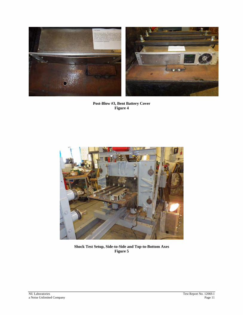
Post-Blow #3, Bent Battery Cover Figure 4
Shock Test Setup, Side-to-Side and Top-to-Bottom Axes Figure 5
NU Laboratories Test Report No. 12069.1 a Noise Unlimited Company Page 11
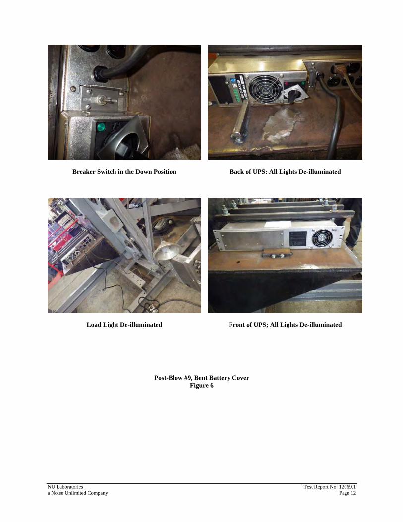
Breaker Switch in the Down Position
Load Light De-illuminated
Back of UPS; All Lights De-illuminated
Front of UPS; All Lights De-illuminated
Post-Blow #9, Bent Battery Cover Figure 6
NU Laboratories Test Report No. 12069.1 a Noise Unlimited Company Page 12
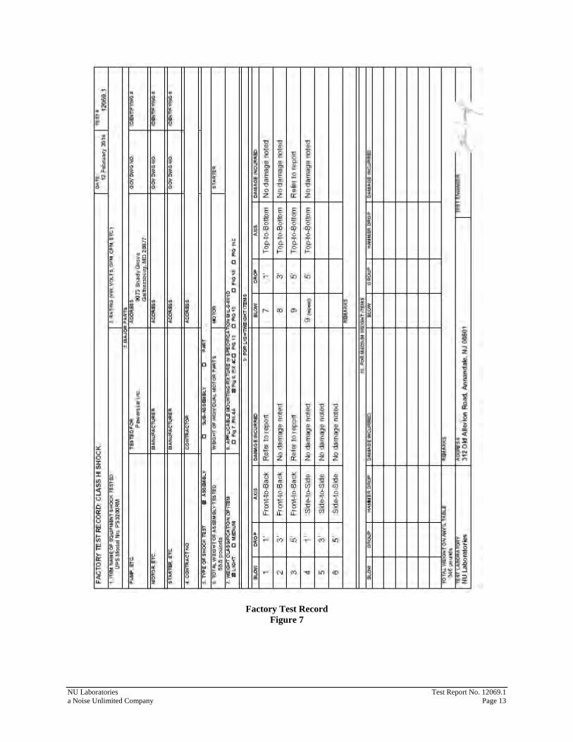
Factory Test Record Figure 7
NU Laboratories Test Report No. 12069.1 a Noise Unlimited Company Page 13
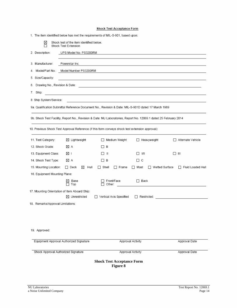
Shock Test Acceptance Form Figure 8
NU Laboratories Test Report No. 12069.1 a Noise Unlimited Company Page 14
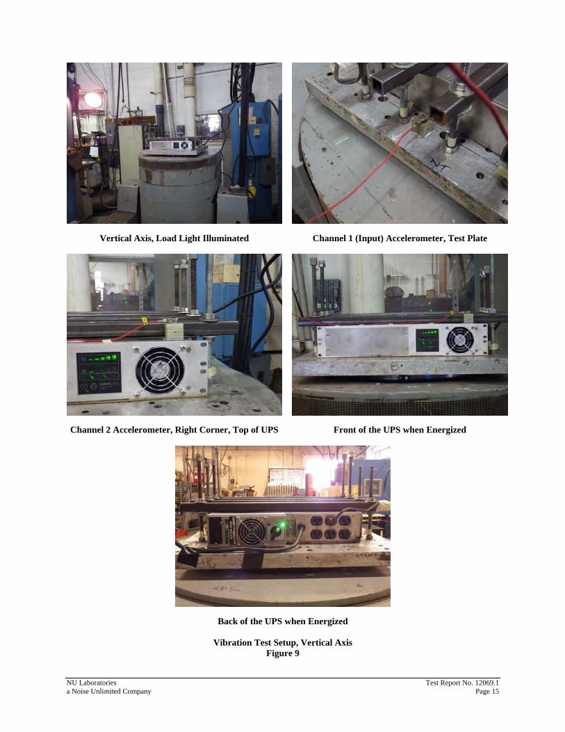
Vertical Axis, Load Light Illuminated
Channel 2 Accelerometer, Right Corner, Top of UPS
Channel 1 (Input) Accelerometer, Test Plate
Front of the UPS when Energized
Back of the UPS when Energized
Vibration Test Setup, Vertical Axis Figure 9
NU Laboratories Test Report No. 12069.1 a Noise Unlimited Company Page 15
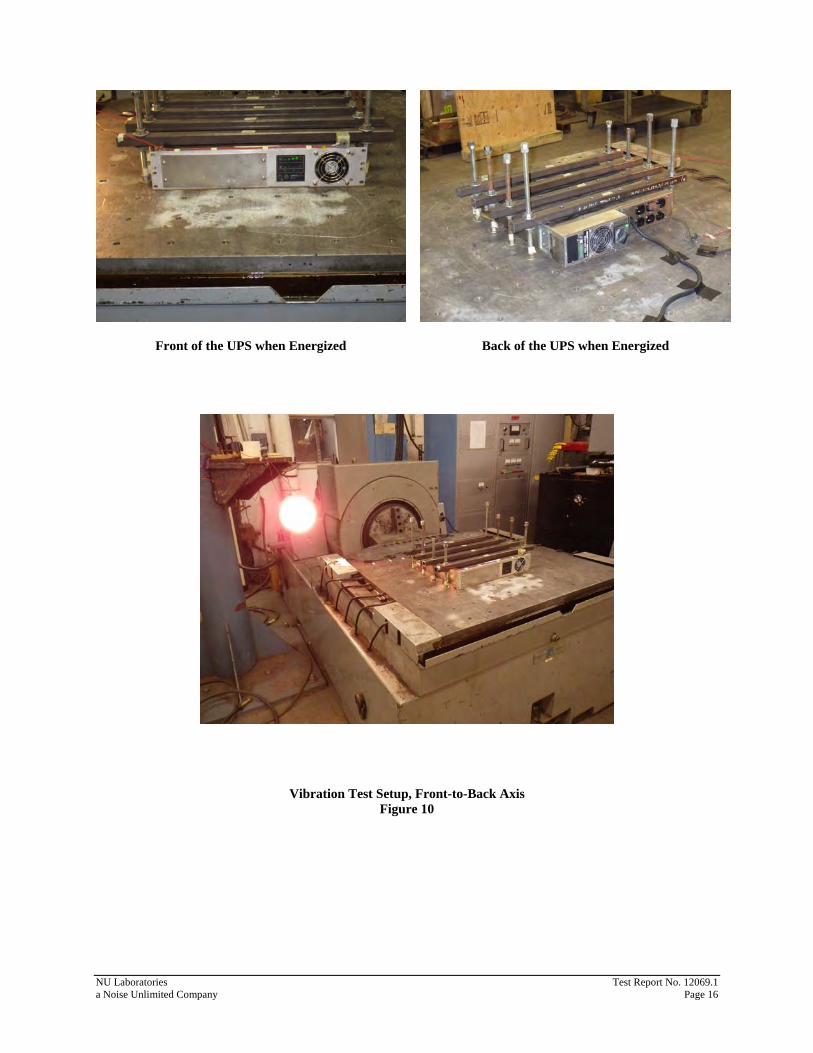
Front of the UPS when Energized
Back of the UPS when Energized
Vibration Test Setup, Front-to-Back Axis Figure 10
NU Laboratories Test Report No. 12069.1 a Noise Unlimited Company Page 16
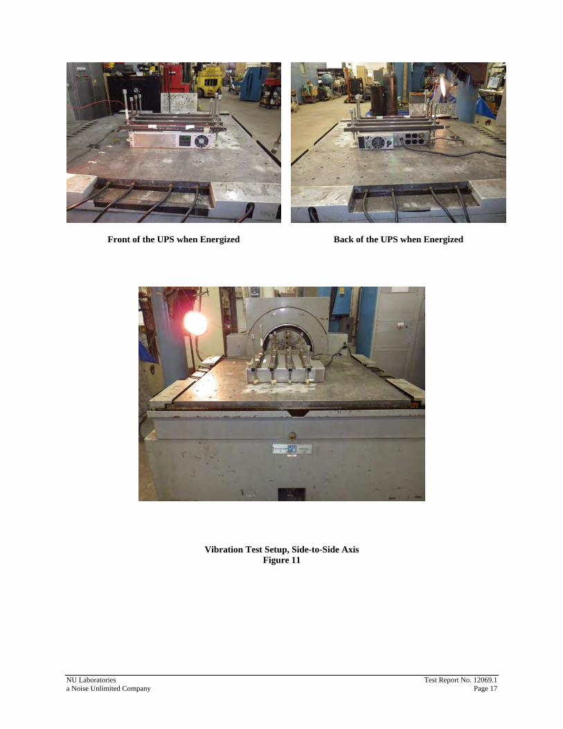
Front of the UPS when Energized
Back of the UPS when Energized
Vibration Test Setup, Side-to-Side Axis Figure 11
NU Laboratories Test Report No. 12069.1 a Noise Unlimited Company Page 17
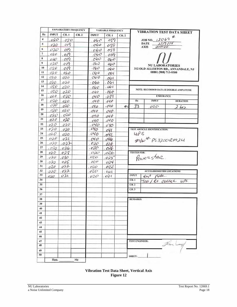
Vibration Test Data Sheet, Vertical Axis Figure 12
NU Laboratories Test Report No. 12069.1 a Noise Unlimited Company Page 18
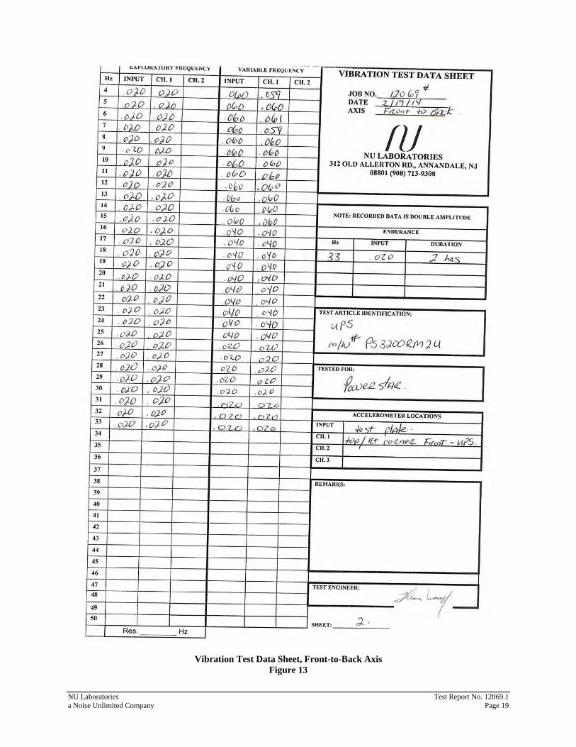
Vibration Test Data Sheet, Front-to-Back Axis Figure 13
NU Laboratories Test Report No. 12069.1 a Noise Unlimited Company Page 19
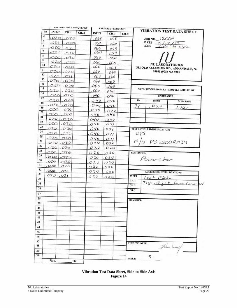
Vibration Test Data Sheet, Side-to-Side Axis Figure 14
NU Laboratories Test Report No. 12069.1 a Noise Unlimited Company Page 20
NU Laboratories Test Report No. 12069.1 a Noise Unlimited Company Page 21
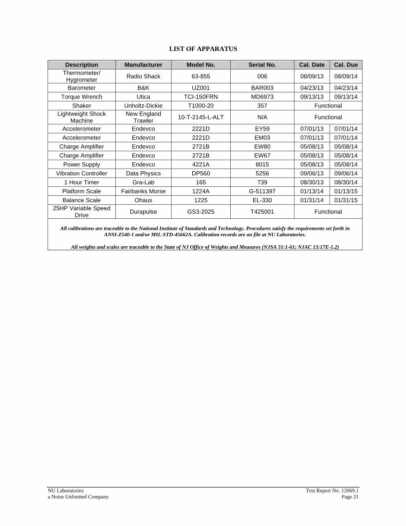
LIST OF APPARATUS
Description Manufacturer Model No. Serial No. Cal. Date Cal. Due Thermometer/ Hygrometer Radio Shack 63-855 006 08/09/13 08/09/14
Barometer B&K UZ001 BAR003 04/23/13 04/23/14 Torque Wrench Utica TCI-150FRN MD6973 09/13/13 09/13/14
Shaker Unholtz-Dickie T1000-20 357 Functional Lightweight Shock
Machine New England
Trawler 10-T-2145-L-ALT N/A Functional
Accelerometer Endevco 2221D EY59 07/01/13 07/01/14 Accelerometer Endevco 2221D EM03 07/01/13 07/01/14
Charge Amplifier Endevco 2721B EW80 05/08/13 05/08/14 Charge Amplifier Endevco 2721B EW67 05/08/13 05/08/14
Power Supply Endevco 4221A 8015 05/08/13 05/08/14 Vibration Controller Data Physics DP560 5256 09/06/13 09/06/14
1 Hour Timer Gra-Lab 165 739 08/30/13 08/30/14 Platform Scale Fairbanks Morse 1224A G-511397 01/13/14 01/13/15 Balance Scale Ohaus 1225 EL-330 01/31/14 01/31/15
25HP Variable Speed Drive Durapulse GS3-2025 T425001 Functional
All calibrations are traceable to the National Institute of Standards and Technology. Procedures satisfy the requirements set forth in
ANSI-Z540-1 and/or MIL-STD-45662A. Calibration records are on file at NU Laboratories.
All weights and scales are traceable to the State of NJ Office of Weights and Measures (NJSA 51:1-61; NJAC 13:17E-1.2)