Embed Size (px)
Citation preview

Line 3 Replacement Project Final Report:
Criteria for Pipe Wall Thickness ‐
Railroad Crossings Job #: 091510044
Submitted: May 1, 2015
Prepared for:
Enbridge Energy
Attention:
Mitch Repka, Manager Engineering and Construction
1409 Hammond Ave
Superior, WI 54880
Simonson Direct CN & PPL Testimony, Ex. ___, Schedule 3 Page 1 of 30
Excellence & Integrity
Criteria for Pipe Wall Thickness ‐ Railroad Crossings Page | 1
TABLE OF CONTENTS 1 EXECUTIVE SUMMARY ........................................................................................................................................... 3
2 BACKGROUND ....................................................................................................................................................... 3
3 OBJECTIVES AND APPROACH ................................................................................................................................. 3
3.1 PURPOSE ....................................................................................................................................................... 3
3.2 DESIGN CRITERIA ............................................................................................................................................ 3
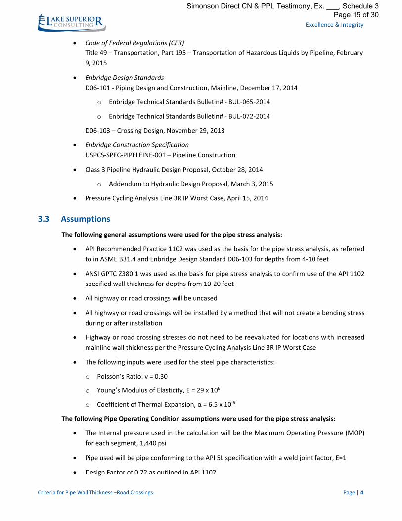
3.3 ASSUMPTIONS ................................................................................................................................................ 4
3.4 ACCEPTABLE STRESS LEVELS – CODE AND STANDARDS REVIEW .............................................................................. 5
4 CONCLUSION ......................................................................................................................................................... 6
5 RECOMMENDATIONS ............................................................................................................................................ 6
APPENDIX I ‐ RESULTS ................................................................................................................................................... 7
Simonson Direct CN & PPL Testimony, Ex. ___, Schedule 3 Page 2 of 30

Simonson Direct CN & PPL Testimony, Ex. ___, Schedule 3 Page 3 of 30

Excellence & Integrity
Criteria for Pipe Wall Thickness ‐ Railroad Crossings Page | 3
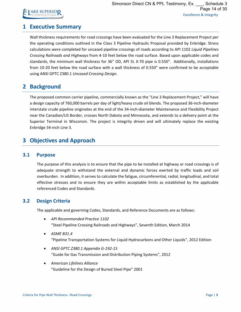
1 Executive Summary
Wall thickness requirements for railroad crossings have been evaluated for the Line 3 Replacement Project
per the operating conditions outlined in the Class 3 Pipeline Hydraulic Proposal provided by Enbridge. Stress
calculations were completed for uncased pipeline crossings of railroads according to API 1102 Liquid
Pipelines Crossing Railroads and Highways from 6‐14 feet below the rail. A minimum wall thickness 0.741”
was determined based on applicable codes and standards. The most stringent requirement is Hoop Stress
calculated with a design factor of 0.50 based on Enbridge Design Standard D06‐103, which exceeds API 1102
and the AREMA manual minimum thickness requirements. For cased crossings of railroads the minimum
wall thickness of the casing pipe can be determined from the AREMA manual. For 46” casing the minimum
wall thickness for uncoated or not catholically protected pipe is 0.656” and must have a SMYS of at least
35,000 psi.
2 Background
The proposed common carrier pipeline, commercially known as the “Line 3 Replacement Project,” will have
a design capacity of 760,000 barrels per day of light/heavy crude oil blends. The proposed 36‐inch‐diameter
interstate crude pipeline originates at the end of the 34‐inch‐diameter Maintenance and Flexibility Project
near the Canadian/US Border, crosses North Dakota and Minnesota, and extends to a delivery point at the
Superior Terminal in Wisconsin. The project is integrity driven and will ultimately replace the existing
Enbridge 34‐inch Line 3.
3 Objectives and Approach
3.1 Purpose
The purpose of this analysis is to ensure that the pipe to be installed at railroad crossings is of adequate
strength to withstand the external and dynamic forces exerted by rail loads and soil overburden. In
addition, it serves to calculate the fatigue, circumferential, radial, longitudinal, and total effective
stresses and to ensure they are within acceptable limits as established by the applicable referenced
Codes and Standards.
3.2 Design Criteria
The applicable and governing Codes, Standards, and Reference Documents are as follows:
American Railroad Engineering and Maintenance‐of‐Way Association (AREMA)
Chapter 1 Part 5 – Pipelines, 2014 Edition
API Recommended Practice 1102
“Steel Pipeline Crossing Railroads and Highways”, Seventh Edition, March 2014
ASME B31.4
“Pipeline Transportation Systems for Liquid Hydrocarbons and Other Liquids”, 2012 Edition
Simonson Direct CN & PPL Testimony, Ex. ___, Schedule 3 Page 4 of 30
Excellence & Integrity
Criteria for Pipe Wall Thickness ‐ Railroad Crossings Page | 4
Code of Federal Regulations (CFR)
Title 49 – Transportation, Part 195 – Transportation of Hazardous Liquids by Pipeline, February
9, 2015
Enbridge Design Standards
D06‐101 ‐ Piping Design and Construction, Mainline, December 17, 2014
o Enbridge Technical Standards Bulletin# ‐ BUL-065-2014
o Enbridge Technical Standards Bulletin# ‐ BUL-072-2014
D06‐103 – Crossing Design, November 29, 2013
Enbridge Construction Specification
USPCS‐SPEC‐PIPELEINE‐001 – Pipeline Construction
Class 3 Pipeline Hydraulic Design Proposal, October 28, 2014
o Addendum to Hydraulic Design Proposal, March 3, 2015
Pressure Cycling Analysis Line 3R IP Worst Case, April 15, 2014
3.3 Assumptions
The following general assumptions were used for the pipe stress analysis:
API Recommended Practice 1102 was used as the basis for the pipe stress analysis, as referred
to in ASME B31.4 and Enbridge Design Standard D06‐103
The analysis was completed for uncased crossings, for cased crossings refer to the wall thickness
requirements in the AREMA manual
All railroad crossings will be installed by a method that will not create bending stress during or
after installation
Pipeline analysis was completed for main transit railroads, not industrial or secondary spurs
Railroad crossing stresses do not need to be reevaluated for locations with increased mainline
wall thickness per the Pressure Cycling Analysis
Cooper E‐80 live loading was used per API 1102
Railroad crossing stresses do not need to be reevaluated for locations with increased mainline
wall thickness per the Pressure Cycling Analysis Line 3R IP Worst Case
The following inputs were used for the steel pipe characteristics:
o Poisson’s Ratio, ν = 0.30
o Young’s Modulus of Elasticity, E = 29 x 106
o Coefficient of Thermal Expansion, α = 6.5 x 10‐6
Simonson Direct CN & PPL Testimony, Ex. ___, Schedule 3 Page 5 of 30
Excellence & Integrity
Criteria for Pipe Wall Thickness ‐ Railroad Crossings Page | 5
The following Pipe Operating Condition assumptions were used for the pipe stress analysis:
The internal pressure used in the calculation will be the Maximum Operating Pressure (MOP)
for each segment, 1440psi
Pipe used will be pipe conforming to the API 5L specification with a weld joint factor, E=1
Design Factor of 0.50, as outlined in Enbridge Design Standard D06‐103
A pipe operating temperature of 140oF
The following Site and Installation assumptions were used for the pipe stress analysis:
Minimum depth of cover for uncased railroad crossings will be 10ft, per AREMA manual
Minimum depth of cover for cased crossings will be 6ft as specified in Enbridge Design Standard
D06‐103
A maximum overbore of 2 inches per Enbridge Construction Specification USPCS‐SPEC‐
PIPELEINE‐001
A conservative installation temperature of 0oF. Actual installation temperatures are expected to
be higher as the construction will be completed during the summer/fall months
Pipeline to cross a single track
Geotechnical data as assumed per API 1102
o Average Unit Weight of Soil, γ = 120 lb/ft3
o Modulus of Soil Reaction, E’=0.5 ksi
o Resilient Modulus of Soil, Er=5.0 ksi
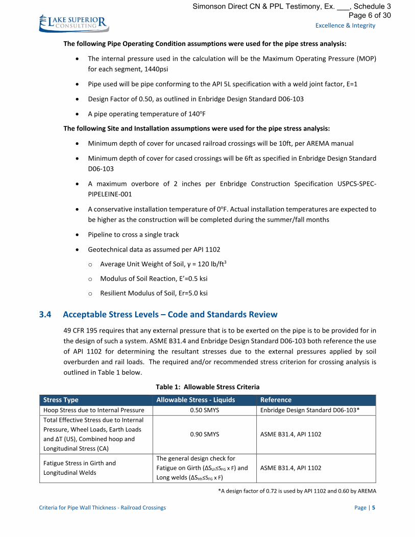
3.4 Acceptable Stress Levels – Code and Standards Review
49 CFR 195 requires that any external pressure that is to be exerted on the pipe is to be provided for in
the design of such a system. ASME B31.4 and Enbridge Design Standard D06‐103 both reference the use
of API 1102 for determining the resultant stresses due to the external pressures applied by soil
overburden and rail loads. The required and/or recommended stress criterion for crossing analysis is
outlined in Table 1 below.
Table 1: Allowable Stress Criteria
Stress Type Allowable Stress ‐ Liquids Reference
Hoop Stress due to Internal Pressure 0.50 SMYS Enbridge Design Standard D06‐103*
Total Effective Stress due to Internal
Pressure, Wheel Loads, Earth Loads
and ΔT (US), Combined hoop and
Longitudinal Stress (CA)
0.90 SMYS ASME B31.4, API 1102
Fatigue Stress in Girth and
Longitudinal Welds
The general design check for
Fatigue on Girth (ΔSLh≤SFG x F) and
Long welds (ΔSHh≤SFG x F)
ASME B31.4, API 1102
*A design factor of 0.72 is used by API 1102 and 0.60 by AREMA
Simonson Direct CN & PPL Testimony, Ex. ___, Schedule 3 Page 6 of 30
Excellence & Integrity
Criteria for Pipe Wall Thickness ‐ Railroad Crossings Page | 6
4 Conclusion
The wall thickness for railroad crossings is calculated to achieve the maximum operating pressure (MOP) in
accordance with applicable codes, standards, and projected operating conditions of the proposed Line 3
Replacement Project. The calculations were completed in accordance with AREMA, ASME – B31.4, API ‐
1102, Enbridge Design Standards D06‐101 – Piping Design and Construction and D06‐103 – Crossing Design,
and the Enbridge Construction Specification ‐ USPCS‐SPEC‐PIPELINE‐001.
The evaluation included reviewing Enbridge Design Standard D06‐101, to confirm adherence, it should be
noted that the current design temperature of 140°F is higher than the maximum allowable design
temperature of 100°F as stated in the Technical Standards Bulletin BUL‐065‐2014 associated with Enbridge
Design Standard D06‐101. It is LSC’s understanding that a project decision record is being developed. The
current design temperature is within the acceptable limits for railroad crossing pipe as outlined in ASME
B31.4 2012 Edition, such that it is not necessary to vary the design calculation.
The railroad crossing wall thickness is calculated to meet the minimum thickness required for the MOP,
operating conditions as defined in the Class 3 Hydraulic Design Proposal, and rail traffic and soil overburden
loading. In addition, it serves to calculate the fatigue, circumferential, radial, longitudinal, and total effective
stresses and to ensure they are within acceptable limits as established by the applicable referenced Codes
and Standards.
5 Recommendations
An analysis was completed to determine if the mainline nominal wall thickness of 0.515” met the strength
requirements for an uncased railroad installation for depths from 6‐14 feet. The stress analysis showed that
pipe with a wall thickness of 0.515” would not meet the hoop stress or total effective stress limits as defined
by the codes and standards.
A minimum wall thickness of 0.741” was found to meet the criteria of 50% hoop stress as described in
Enbridge Design Standard D06‐103, which is the most stringent specification. Other criteria that was
analyzed included Barlow stress, effective stress, and weld fatigue for uncased railroad installations. This
wall thickness is acceptable at depths from 6‐14 feet per the API 1102 stress calculations.
If the railroad is crossed using a casing pipe, the inside diameter of the casing pipe shall be large enough to
allow the carrier pipe to be installed within the casing, taking into account spacing between the carrier pipe
and casing pipe. The wall thickness of casing, pipe can be determined from the AREMA manual. A
recommended casing OD of 46” would require a wall thickness for uncoated or not catholically protected
pipe of 0.656”, and must have a SMYS of at least 35,000 psi.
Simonson Direct CN & PPL Testimony, Ex. ___, Schedule 3 Page 7 of 30
Excellence & Integrity
Criteria for Pipe Wall Thickness ‐ Railroad Crossings Page | 7
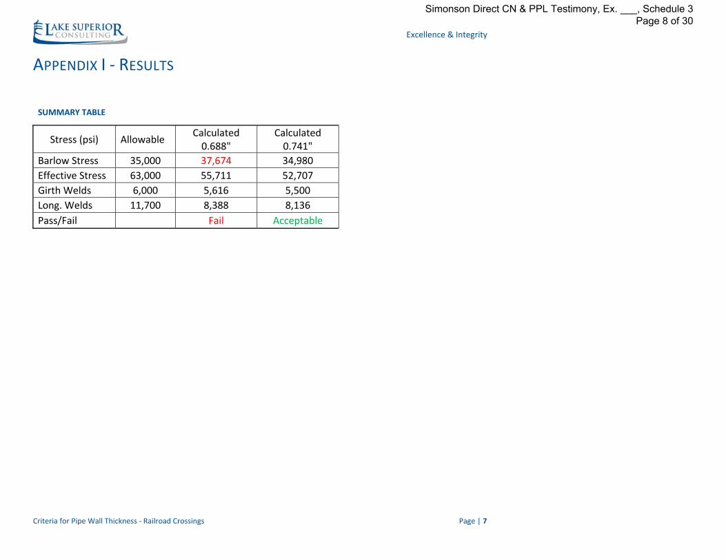
APPENDIX I ‐ RESULTS
SUMMARY TABLE
Stress (psi) Allowable Calculated 0.688"
Calculated 0.741"
Barlow Stress 35,000 37,674 34,980
Effective Stress 63,000 55,711 52,707
Girth Welds 6,000 5,616 5,500
Long. Welds 11,700 8,388 8,136
Pass/Fail Fail Acceptable
Simonson Direct CN & PPL Testimony, Ex. ___, Schedule 3 Page 8 of 30
Excellence & Integrity
Criteria for Pipe Wall Thickness ‐ Railroad Crossings Page | 8
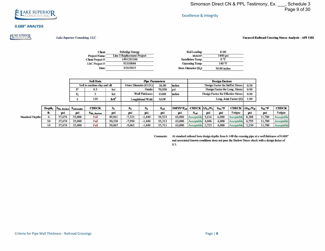
0.688” ANALYSIS
Simonson Direct CN & PPL Testimony, Ex. ___, Schedule 3 Page 9 of 30
Excellence & Integrity
Criteria for Pipe Wall Thickness ‐ Railroad Crossings Page | 9
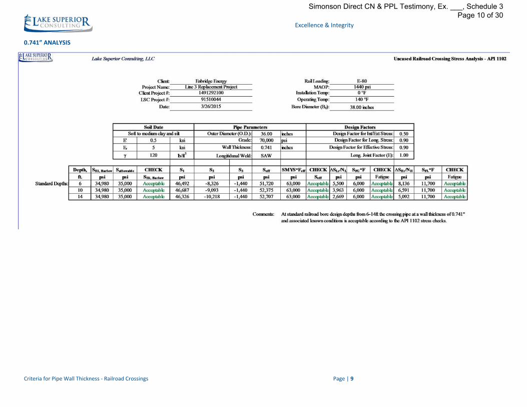
0.741” ANALYSIS
Simonson Direct CN & PPL Testimony, Ex. ___, Schedule 3 Page 10 of 30
Line 3 Replacement Project Final Report:
Criteria for Pipe Wall Thickness –
Road Crossings Job #: 091510044
Submitted: May 1, 2015
Prepared for:
Enbridge Energy
Attention:
Mitch Repka, Manager Engineering and Construction
1409 Hammond Ave
Superior, WI 54880
Simonson Direct CN & PPL Testimony, Ex. ___, Schedule 3 Page 11 of 30
Excellence & Integrity
Criteria for Pipe Wall Thickness –Road Crossings Page | 1
TABLE OF CONTENTS 1 EXECUTIVE SUMMARY ........................................................................................................................................... 3
2 BACKGROUND ....................................................................................................................................................... 3
3 OBJECTIVES AND APPROACH ................................................................................................................................. 3
3.1 PURPOSE ....................................................................................................................................................... 3
3.2 DESIGN CRITERIA ............................................................................................................................................ 3
3.3 ASSUMPTIONS ................................................................................................................................................ 4
3.4 ACCEPTABLE STRESS LEVELS – CODE AND STANDARDS REVIEW .............................................................................. 5
4 CONCLUSION ......................................................................................................................................................... 6
5 RECOMMENDATIONS ............................................................................................................................................ 6
APPENDIX I ‐ RESULTS ................................................................................................................................................... 7
Simonson Direct CN & PPL Testimony, Ex. ___, Schedule 3 Page 12 of 30
Simonson Direct CN & PPL Testimony, Ex. ___, Schedule 3 Page 13 of 30
Excellence & Integrity
Criteria for Pipe Wall Thickness –Road Crossings Page | 3
1 Executive Summary
Wall thickness requirements for road crossings have been evaluated for the Line 3 Replacement Project per
the operating conditions outlined in the Class 3 Pipeline Hydraulic Proposal provided by Enbridge. Stress
calculations were completed for uncased pipeline crossings of roads according to API 1102 Liquid Pipelines
Crossing Railroads and Highways from 4‐10 feet below the road surface. Based upon applicable codes and
standards, the minimum wall thickness for 36” OD, API 5L X‐70 pipe is 0.550”. Additionally, installations
from 10‐20 feet below the road surface with a wall thickness of 0.550” were confirmed to be acceptable
using ANSI GPTC Z380.1 Uncased Crossing Design.
2 Background
The proposed common carrier pipeline, commercially known as the “Line 3 Replacement Project,” will have
a design capacity of 760,000 barrels per day of light/heavy crude oil blends. The proposed 36‐inch‐diameter
interstate crude pipeline originates at the end of the 34‐inch‐diameter Maintenance and Flexibility Project
near the Canadian/US Border, crosses North Dakota and Minnesota, and extends to a delivery point at the
Superior Terminal in Wisconsin. The project is integrity driven and will ultimately replace the existing
Enbridge 34‐inch Line 3.
3 Objectives and Approach
3.1 Purpose
The purpose of this analysis is to ensure that the pipe to be installed at highway or road crossings is of
adequate strength to withstand the external and dynamic forces exerted by traffic loads and soil
overburden. In addition, it serves to calculate the fatigue, circumferential, radial, longitudinal, and total
effective stresses and to ensure they are within acceptable limits as established by the applicable
referenced Codes and Standards.
3.2 Design Criteria
The applicable and governing Codes, Standards, and Reference Documents are as follows:
API Recommended Practice 1102
“Steel Pipeline Crossing Railroads and Highways”, Seventh Edition, March 2014
ASME B31.4
“Pipeline Transportation Systems for Liquid Hydrocarbons and Other Liquids”, 2012 Edition
ANSI GPTC Z380.1 Appendix G‐192‐15
“Guide for Gas Transmission and Distribution Piping Systems”, 2012
American Lifelines Alliance
"Guideline for the Design of Buried Steel Pipe" 2001
Simonson Direct CN & PPL Testimony, Ex. ___, Schedule 3 Page 14 of 30
Excellence & Integrity
Criteria for Pipe Wall Thickness –Road Crossings Page | 4
Code of Federal Regulations (CFR)
Title 49 – Transportation, Part 195 – Transportation of Hazardous Liquids by Pipeline, February
9, 2015
Enbridge Design Standards
D06‐101 ‐ Piping Design and Construction, Mainline, December 17, 2014
o Enbridge Technical Standards Bulletin# ‐ BUL-065-2014
o Enbridge Technical Standards Bulletin# ‐ BUL-072-2014
D06‐103 – Crossing Design, November 29, 2013
Enbridge Construction Specification
USPCS‐SPEC‐PIPELEINE‐001 – Pipeline Construction
Class 3 Pipeline Hydraulic Design Proposal, October 28, 2014
o Addendum to Hydraulic Design Proposal, March 3, 2015
Pressure Cycling Analysis Line 3R IP Worst Case, April 15, 2014
3.3 Assumptions
The following general assumptions were used for the pipe stress analysis:
API Recommended Practice 1102 was used as the basis for the pipe stress analysis, as referred
to in ASME B31.4 and Enbridge Design Standard D06‐103 for depths from 4‐10 feet
ANSI GPTC Z380.1 was used as the basis for pipe stress analysis to confirm use of the API 1102
specified wall thickness for depths from 10‐20 feet
All highway or road crossings will be uncased
All highway or road crossings will be installed by a method that will not create a bending stress
during or after installation
Highway or road crossing stresses do not need to be reevaluated for locations with increased
mainline wall thickness per the Pressure Cycling Analysis Line 3R IP Worst Case
The following inputs were used for the steel pipe characteristics:
o Poisson’s Ratio, ν = 0.30
o Young’s Modulus of Elasticity, E = 29 x 106
o Coefficient of Thermal Expansion, α = 6.5 x 10‐6
The following Pipe Operating Condition assumptions were used for the pipe stress analysis:
The Internal pressure used in the calculation will be the Maximum Operating Pressure (MOP)
for each segment, 1,440 psi
Pipe used will be pipe conforming to the API 5L specification with a weld joint factor, E=1
Design Factor of 0.72 as outlined in API 1102
Simonson Direct CN & PPL Testimony, Ex. ___, Schedule 3 Page 15 of 30

Excellence & Integrity
Criteria for Pipe Wall Thickness –Road Crossings Page | 5
A pipe operating temperature of 140oF;
The following Site and Installation assumptions were used for the pipe stress analysis:
Minimum depth of cover for highway and road crossings will be 4 feet as specified in API 1102
and Enbridge Design Standard D06‐103
A maximum overbore of 2 inches per, Enbridge Construction Specification USPCS‐SPEC‐
PIPELEINE‐001
A conservative installation temperature of 0oF. Actual installation temperatures are expected to
be higher as the construction will be completed during the summer/fall months
Design wheel load for a single axle of 12,000lbs, as recommended by API 1102 for the maximum
design load for a single axle
Design wheel load for a tandem axle of 10,000lbs, as recommended by API 1102 for the
maximum design load for a tandem axle
Tandem axle loading is the critical loading for all diameters at depths greater than 4 feet, per
API 1102 Table 1
Unpaved Roads. By API 1102 this would be the most conservative approach as asphalt or
concrete would not be present to aid in distributing the traffic loads
Geotechnical data as assumed by API 1102:
o Average Unit Weight of Soil, γ = 120 lb/ft3
o Modulus of Soil Reaction, E’=0.2 ksi
o Resilient Modulus of Soil, Er=5.0 ksi
3.4 Acceptable Stress Levels – Code and Standards Review
CFR 195 requires that any external pressure that is to be exerted on the pipe to be provided for in the
design of such a system. ASME B31.4 and Enbridge D06‐103 both reference the use of API 1102 for
determining the resultant stresses due to the external pressures applied by soil overburden and traffic
loads. The required and/or recommended stress criterion for crossing analysis is outlined in Table 1
below.
Table 1: Allowable Stress Criteria
Stress Type Allowable Stress ‐ Liquids Reference
Hoop Stress due to Internal Pressure 0.72 SMYS CFR 195, ASME B31.4
Longitudinal Stress due to ΔT, Wheel Loads
and Earth Loads 0.90 SMYS ASME B31.4
Total Effective Stress due to Internal
Pressure, Wheel Loads, Earth Loads and ΔT
(US), Combined hoop and Longitudinal
Stress (CA)
0.90 SMYS ASME B31.4, API 1102
Fatigue Stress in Girth and Longitudinal
Welds
The general design check for Fatigue on Girth
(ΔSLh≤SFG x F) and Long welds (ΔSHh≤SFG x F) ASME B31.4, API 1102
Simonson Direct CN & PPL Testimony, Ex. ___, Schedule 3 Page 16 of 30
Excellence & Integrity
Criteria for Pipe Wall Thickness –Road Crossings Page | 6
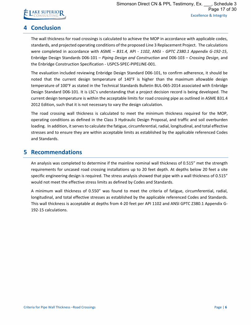
4 Conclusion
The wall thickness for road crossings is calculated to achieve the MOP in accordance with applicable codes,
standards, and projected operating conditions of the proposed Line 3 Replacement Project. The calculations
were completed in accordance with ASME – B31.4, API ‐ 1102, ANSI ‐ GPTC Z380.1 Appendix G‐192‐15,
Enbridge Design Standards D06‐101 – Piping Design and Construction and D06‐103 – Crossing Design, and
the Enbridge Construction Specification ‐ USPCS‐SPEC‐PIPELINE‐001.
The evaluation included reviewing Enbridge Design Standard D06‐101, to confirm adherence, it should be
noted that the current design temperature of 140°F is higher than the maximum allowable design
temperature of 100°F as stated in the Technical Standards Bulletin BUL‐065‐2014 associated with Enbridge
Design Standard D06‐101. It is LSC’s understanding that a project decision record is being developed. The
current design temperature is within the acceptable limits for road crossing pipe as outlined in ASME B31.4
2012 Edition, such that it is not necessary to vary the design calculation.
The road crossing wall thickness is calculated to meet the minimum thickness required for the MOP,
operating conditions as defined in the Class 3 Hydraulic Design Proposal, and traffic and soil overburden
loading. In addition, it serves to calculate the fatigue, circumferential, radial, longitudinal, and total effective
stresses and to ensure they are within acceptable limits as established by the applicable referenced Codes
and Standards.
5 Recommendations
An analysis was completed to determine if the mainline nominal wall thickness of 0.515” met the strength
requirements for uncased road crossing installations up to 20 feet depth. At depths below 20 feet a site
specific engineering design is required. The stress analysis showed that pipe with a wall thickness of 0.515”
would not meet the effective stress limits as defined by Codes and Standards.
A minimum wall thickness of 0.550” was found to meet the criteria of fatigue, circumferential, radial,
longitudinal, and total effective stresses as established by the applicable referenced Codes and Standards.
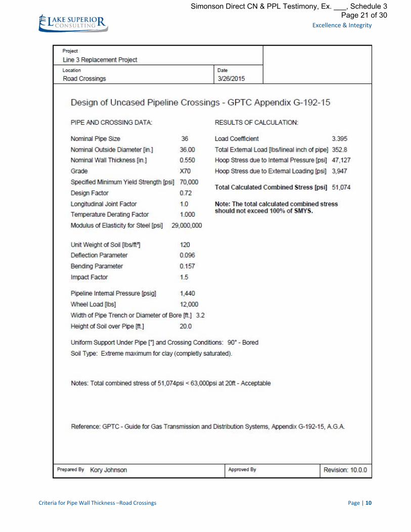
This wall thickness is acceptable at depths from 4‐20 feet per API 1102 and ANSI GPTC Z380.1 Appendix G‐
192‐15 calculations.
Simonson Direct CN & PPL Testimony, Ex. ___, Schedule 3 Page 17 of 30

Excellence & Integrity
Criteria for Pipe Wall Thickness –Road Crossings Page | 7
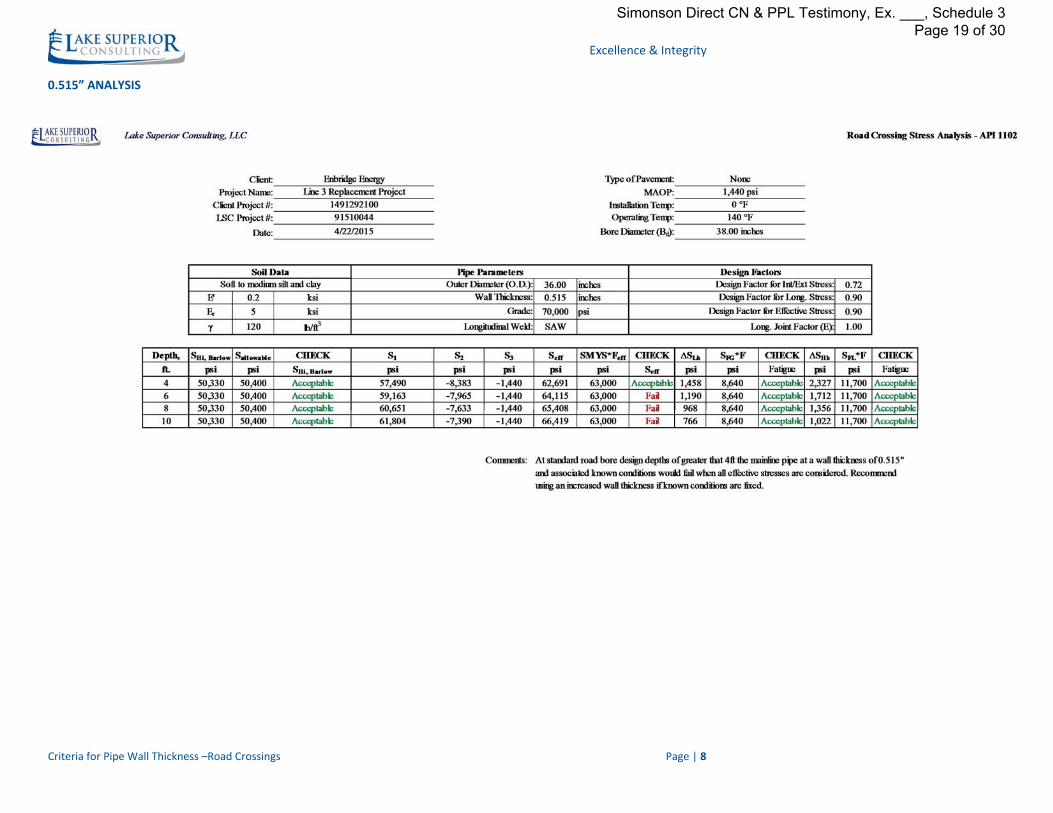
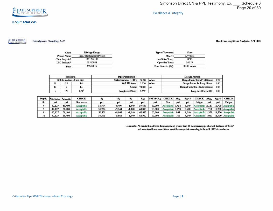
APPENDIX I ‐ RESULTS
SUMMARY TABLE
Stress (psi) Allowable Calculated 0.515"
Calculated 0.550"
Barlow Stress 50,400 50,330 47,127
Effective Stress 63,000 66,419 62,927
Girth Welds 8,640 1,458 1,458
Long. Welds 11,700 2,327 2,329
Pass/Fail Fail Acceptable
Simonson Direct CN & PPL Testimony, Ex. ___, Schedule 3 Page 18 of 30
Excellence & Integrity
Criteria for Pipe Wall Thickness –Road Crossings Page | 8
0.515” ANALYSIS
Simonson Direct CN & PPL Testimony, Ex. ___, Schedule 3 Page 19 of 30
Excellence & Integrity
Criteria for Pipe Wall Thickness –Road Crossings Page | 9
0.550” ANALYSIS
Simonson Direct CN & PPL Testimony, Ex. ___, Schedule 3 Page 20 of 30
Excellence & Integrity
Criteria for Pipe Wall Thickness –Road Crossings Page | 10
Simonson Direct CN & PPL Testimony, Ex. ___, Schedule 3 Page 21 of 30
Line 3 Replacement Project Final Report:
Criteria for Pipe Wall Thickness ‐ MainlineJob #: 091510044
Submitted: May 1, 2015
Prepared for:
Enbridge Energy
Attention:
Mitch Repka, Manager Pipeline Engineering & Construction
1409 Hammond Ave.
Superior, WI 54880
Simonson Direct CN & PPL Testimony, Ex. ___, Schedule 3 Page 22 of 30
Excellence & Integrity
Criteria for Pipe Wall Thickness ‐ Mainline Page | 1
TABLE OF CONTENTS 1 EXECUTIVE SUMMARY ........................................................................................................................................... 3
2 BACKGROUND ....................................................................................................................................................... 3
3 OBJECTIVES AND APPROACH ................................................................................................................................. 3
3.1 PURPOSE ....................................................................................................................................................... 3
3.2 DESIGN CRITERIA ............................................................................................................................................ 3
3.3 ASSUMPTIONS ................................................................................................................................................ 4
3.4 APPROACH .................................................................................................................................................... 4
4 CONCLUSION ......................................................................................................................................................... 5
5 RECOMMENDATION .............................................................................................................................................. 5
APPENDIX I ‐ LINE DESCRIPTION SUMMARY .................................................................................................................. 6
APPENDIX II ‐ PRESSURE PROFILE .................................................................................................................................. 7
APPENDIX III ‐ SUMMARY OF RESULTS .......................................................................................................................... 8
Simonson Direct CN & PPL Testimony, Ex. ___, Schedule 3 Page 23 of 30
Simonson Direct CN & PPL Testimony, Ex. ___, Schedule 3 Page 24 of 30
Excellence & Integrity
Criteria for Pipe Wall Thickness ‐ Mainline Page | 3
1 Executive Summary
The minimum wall thickness requirements for mainline pipe have been evaluated for the Line 3 Replacement
Project per the operating conditions outlined in the Class 3 Pipeline Hydraulic Design Proposal provided by
Enbridge. Based upon applicable codes and standards, the minimum wall thickness for 36” OD, API 5L X‐70
pipe is 0.515”.
2 Background
The proposed common carrier pipeline, commercially known as the “Line 3 Replacement Project,” will have
a design capacity of 760,000 barrels per day of light/heavy crude oil blends. The proposed 36‐inch‐diameter
interstate crude pipeline originates at the end of the 34‐inch‐diameter Maintenance and Flexibility Project
near the Canadian/US Border, crosses North Dakota and Minnesota, and extends to a delivery point at the
Superior Terminal in Wisconsin. The project is integrity driven and will ultimately replace the existing
Enbridge 34‐inch Line 3.
3 Objectives and Approach
3.1 Purpose
To determine a nominal wall thickness for mainline pipe satisfying requirements for the maximum
operating pressure (MOP) in accordance with applicable codes, standards, and projected operating
conditions of the proposed Line 3 Replacement Project.
3.2 Design Criteria
The applicable and governing Codes, Standards, and Reference Documents are as follows:
ASME B31.4
“Pipeline Transportation Systems for Liquid Hydrocarbons and Other Liquids”, 2012 Edition
Code of Federal Regulations (CFR)
Title 49 – Transportation, Part 195 – Transportation of Hazardous Liquids by Pipeline, February
9, 2015
Enbridge Design Standards
D06‐101 ‐ Piping Design and Construction, Mainline, December 17, 2014
o Enbridge Technical Standards Bulletin# ‐ BUL-065-2014
o Enbridge Technical Standards Bulletin# ‐ BUL-072-2014
D06‐104 – Pipe and Fittings, Steel, December 18, 2013
o Enbridge Technical Standards Bulletin# ‐ BUL-064-2014
Enbridge Equipment Standard
EES 103 – Submerged‐Arc‐Welded Steel Pipe, November 29, 2013
Simonson Direct CN & PPL Testimony, Ex. ___, Schedule 3 Page 25 of 30
Excellence & Integrity
Criteria for Pipe Wall Thickness ‐ Mainline Page | 4
Class 3 Pipeline Hydraulic Design Proposal, October 28, 2014
o Addendum to Hydraulic Design Proposal, March 3, 2015
Pressure Cycling Analysis Line 3R IP Worst Case, April 15, 2014
3.3 Assumptions
36” outside diameter (OD), in accordance with API 5L X‐70
Maximum operating pressure of 1,440 psi, as outlined in the hydraulic summary
Maximum operating temperature of 140°F, as outlined in the hydraulic summary
Design Factor of 0.72, as outlined in ASME B31.4
Weld Joint Factor of 1, as outlined in ASME B31.4
D/t ratio of less than 100, as outlined in Enbridge Design Standard D06‐101
Additional mainline wall thickness requirements downstream of pump stations were required
from the Pressure Cycling Analysis Line 3R IP Worst Case completed by Enbridge
Wall thickness is rounded up to the nearest thousandth to meet the 0.72 design factor
3.4 Approach
The minimum mainline wall thickness requirement is calculated in accordance with ASME B31.4 and
Enbridge Design Standard D06‐101, using Barlow’s equation and checking the D/t ratio as shown below.
2
Where:
t nominal wall thickness (in)
Pi internal design pressure (psi)
D nominal outside diameter of pipe (in)
S yield strength (psi)
Where:
F design factor based from Table 403.3.1‐1
E weld joint factor
Sy = specified minimum yield strength of the pipe (psi)
Simonson Direct CN & PPL Testimony, Ex. ___, Schedule 3 Page 26 of 30

Excellence & Integrity
Criteria for Pipe Wall Thickness ‐ Mainline Page | 5
100
Where:
D nominal outside diameter of pipe (in)
t nominal wall thickness (in)
4 Conclusion
The nominal wall thickness for mainline pipe is calculated to achieve the MOP in accordance with applicable
codes, standards, and projected operating conditions of the proposed Line 3 Replacement Project. The
calculation was completed using Barlow’s equation as outlined in ASME B31.4 2012 Edition and the Enbridge
Design Standard D06‐101 – Piping Design and Construction.
The evaluation included reviewing Enbridge Design Standard D06‐101, to confirm adherence, and it should
be noted that the current design temperature of 140°F is higher than the maximum allowable design
temperature of 100°F as stated in the Technical Standards Bulletin BUL‐065‐2014 associated with Enbridge
Design Standard D06‐101. It is LSC’s understanding that a project decision record is being developed. The
current design temperature is within the acceptable limits for mainline pipe as outlined in ASME B31.4, such
that it is not necessary to vary the design stress calculation.
The pipe wall thickness was designed to accommodate the MOP profile defined in the Class 3 Hydraulic
Design Proposal, ensuring the MOP between pump stations accounts for elevations at the required discharge
pressures to meet the proposed design capacity (see Appendix I ‐ Line Description Summary and Appendix
II ‐ Pressure Profile).
Further, the diameter to thickness ratio (D/t ratio) was evaluated to determine whether or not the calculated
thickness is susceptible to flattening, ovality, buckling, and denting; a D/t ratio greater than 100 may require
additional protective measures during construction. The D/t ratio for the Line 3 Replacement Project is less
than 100; therefore, as outlined in ASME 31.4 and Enbridge Design standard D06‐101, normal construction
procedures can be followed.
5 Recommendation
The minimum wall thickness for mainline pipe has been evaluated for the Line 3 Replacement Project per
the operating conditions outlined in the Class 3 Pipeline Hydraulic Proposal provided by Enbridge. Based
upon applicable codes and standards, the minimum wall thickness for 36” OD API 5L X‐70 pipe is 0.515”,
resulting in a D/t ratio of 64.1. See Appendix III ‐ Summary of Results for calculations.
The Enbridge Pressure Cycling Analysis recommends additional wall thickness downstream of Clearbrook,
Two Inlets, Backus, and Palisade Stations. Wall thicknesses of 0.750” and 0.600” are specified as mainline
thicknesses to be used. The specific distances downstream of each station can be found in the Pressure
Cycling Analysis Line 3R IP Worst Case, April 15, 2014.
Simonson Direct CN & PPL Testimony, Ex. ___, Schedule 3 Page 27 of 30
Excellence & Integrity
Criteria for Pipe Wall Thickness ‐ Mainline Page | 6
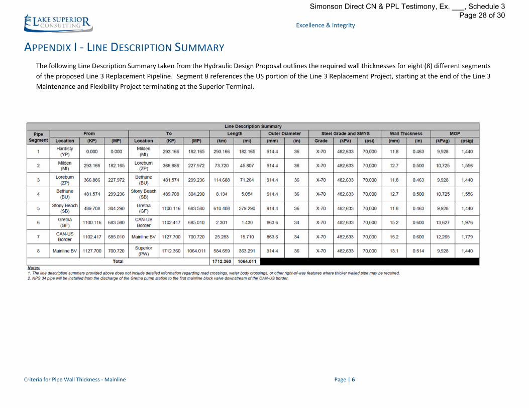
APPENDIX I ‐ LINE DESCRIPTION SUMMARY
The following Line Description Summary taken from the Hydraulic Design Proposal outlines the required wall thicknesses for eight (8) different segments
of the proposed Line 3 Replacement Pipeline. Segment 8 references the US portion of the Line 3 Replacement Project, starting at the end of the Line 3
Maintenance and Flexibility Project terminating at the Superior Terminal.
Simonson Direct CN & PPL Testimony, Ex. ___, Schedule 3 Page 28 of 30
Excellence & Integrity
Criteria for Pipe Wall Thickness ‐ Mainline Page | 7
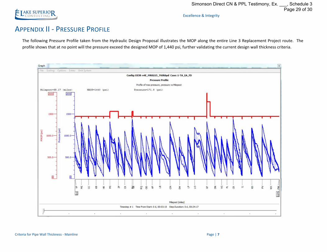
APPENDIX II ‐ PRESSURE PROFILE
The following Pressure Profile taken from the Hydraulic Design Proposal illustrates the MOP along the entire Line 3 Replacement Project route. The
profile shows that at no point will the pressure exceed the designed MOP of 1,440 psi, further validating the current design wall thickness criteria.
Simonson Direct CN & PPL Testimony, Ex. ___, Schedule 3 Page 29 of 30

Excellence & Integrity
Criteria for Pipe Wall Thickness ‐ Mainline Page | 8
APPENDIX III ‐ SUMMARY OF RESULTS
Simonson Direct CN & PPL Testimony, Ex. ___, Schedule 3 Page 30 of 30