Embed Size (px)
Citation preview
3480 IEEE TRANSACTIONS ON SIGNAL PROCESSING, VOL. 41, NO. 12, DECEMBER 1993
Linear Phase Paraunitary Filter Banks: Theory, Factorizations and Designs
Anand K. Soman, Member, IEEE, P. P . Vaidyanathan, Fellow, IEEE, and Truong Q. Nguyen, Member, IEEE
Abstract--M channel maximally decimated filter banks have been used in the past to decompose signals into subbands. The theory of perfect-reconstruction filter banks has also been stud- ied extensively. Nonparaunitary systems with linear phase fil- ters have also been designed. In this paper, we study parauni- tary systems in which each individual filter in the analysis synthesis banks has linear phase. Specific instances of this problem have been addressed by other authors, and linear phase paraunitary systems have been shown to exist. This prop- erty is often desirable for several applications, particularly in image processing.
We begin by answering several theoretical questions pertain- ing to linear phase paraunitary systems. Next, we develop a minimal factorizdion for a large class of such systems. This fac- torization will be proved to be complete for even M . Further, we structurally impose the additional condition that the filters satisfy pairwise mirror-image symmetry in the frequency do- main. This significantly reduces the number of parameters to be optimized in the design process. We then demonstrate the use of these filter banks in the generation of M-band ortho- normal wavelets. Several design examples are also given to val- idate the theory.
I . INTRODUCTION IGITAL filter banks have been used in the past to D decompose a signal into frequency subbands [1]-
[ 121. The signals in different subbands are then coded and transmitted. Such schemes are popular for encoding data from speech and image signals. The process of decom- position and eventual reconstruction are done by what is termed as the “analysis-synthesis’’ filter bank system shown in Fig. 1. In this scheme, the Hi ( z ) are the analysis filters and Fi(z) are the synthesis filters. The boxes with 1M denote the decimators, or the subsampling devices, whereas the boxes with t M denote the expanders, which increase the sampling rate. Their definitions are as in [ 13,
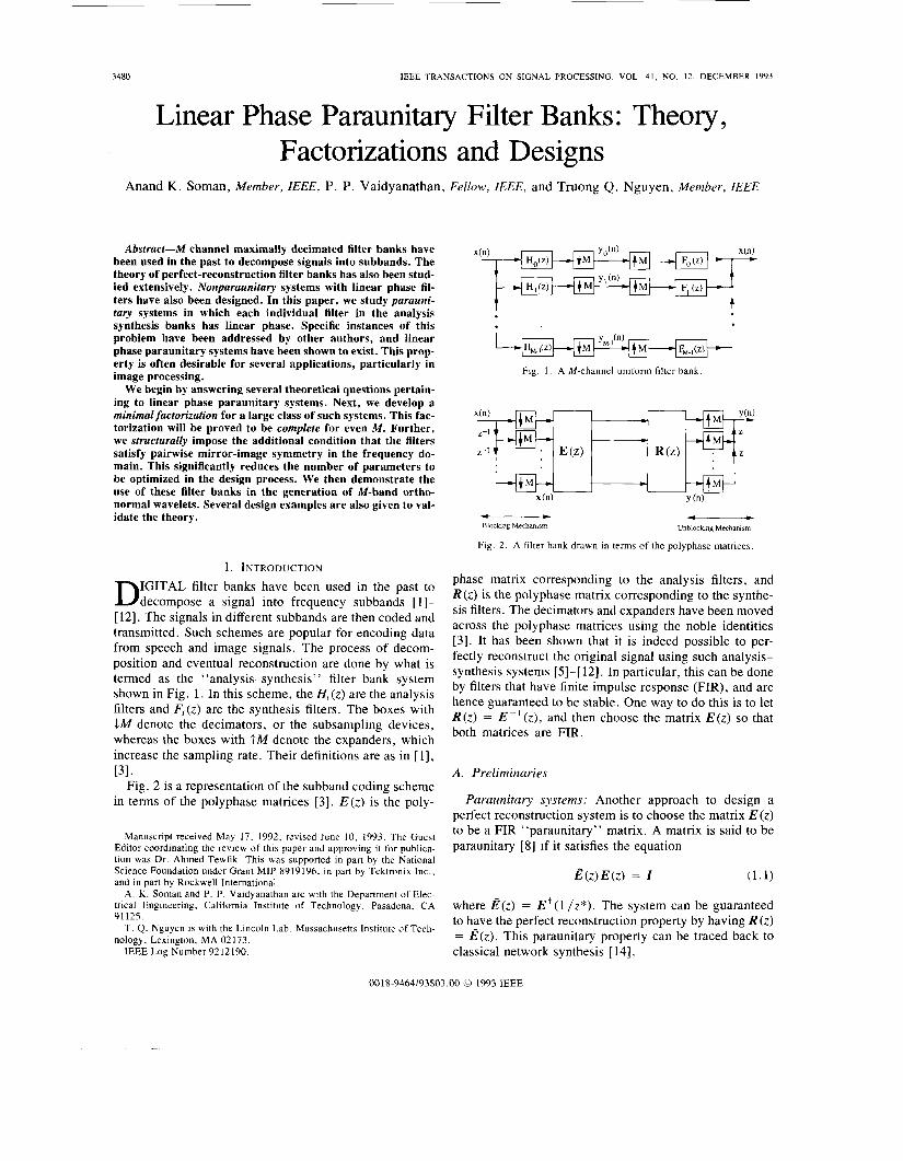
Fig. 2 is a representation of the subband coding scheme in terms of the polyphase matrices [3]. E ( z ) is the poly-
131.
Manuscript received May 17, 1992; revised June 10, 1993. The Guest Editor coordinating the review of this paper and approving it for publica- tion was Dr. Ahmed Tewfik. This was supported in part by the National Science Foundation under Grant MIP 8919196, in part by Tektronix Inc., and in part by Rockwell International.
A. K. Soman and P. P. Vaidyanathan are with the Department of Elec- trical Engineering, California Institute of Technology, Pasadena, CA 91125.
T. Q. Nguyen is with the Lincoln Lab, Massachusetts Institute of Tech- nology, Lexington, MA 02 173.
IEEE Log Number 9212190.
Fig. 1 . A M-channel uniform filter bank
4 - Blocking Mechamsm
P
Unbloclang Mechanism
Fig. 2. A filter bank drawn in terms of the polyphase matrices
phase matrix corresponding to the analysis filters, and R ( z ) is the polyphase matrix corresponding to the synthe- sis filters. The decimators and expanders have been moved across the polyphase matrices using the noble identities [3]. It has been shown that it is indeed possible to per- fectly reconstruct the original signal using such analysis- synthesis systems [5]-[ 121. In particular, this can be done by filters that have finite impulse response (FIR), and are hence guaranteed to be stable. One way to do this is to let R ( z ) = E - ‘ ( z ) , and then choose the matrix E(z ) so that both matrices are FIR.
A . Preliminaries
Paraunitary systems: Another approach to design a perfect reconstruction system is to choose the matrix E ( z ) to be a FIR “paraunitary” matrix. A matrix is said to be paraunitary [XI if it satisfies the equation
B(z)E(z) = I (1.1)
where B(z) = E’(l/z*). The system can be guaranteed to have the perfect reconstruction property by having R ( z ) = E(z) . This paraunitary property can be traced back to classical network synthesis [ 141.
0018-9464/93$03,00 0 1993 IEEE
SOMAN er a l . : LINEAR PHASE PARAUNITARY FILTER BANKS 3481
Consider the synthesis bank of Fig. 1. The original sig- nal can be written in terms of the subband signals as
M - 1
x ( n ) = c C y k ( m ) f k ( n - Mm). (1 .2) k = O m
This can be viewed as a representation of the original sig- nal in terms of a doubly indexed set of basis functions qkm(n) = fk(n - Mm). It is known [lo], [13], [15] that this set of basis functions is orthonormal if and only if the polyphase matrix R ( z ) corresponding to these filters is paraunitary .
Another feature of the paraunitary analysis-synthesis system is that the analysis and synthesis filters are simply time-reversed conjugate versions of each other, and in particular therefore, they are of the same length.
Quantization: In a practical subband coding system, both the filter coefficients, as well as the subband signals are quantized. It has been shown [3], [16] that there exist structures which retain the paraunitary property inspite of coefficient quantization. The perfect-reconstruction prop- erty is however lost, when the signals in each subband are quantized. A paraunitary system still has some important features in the presence of subband quantization:
1) We can obtain bounds on the overall reconstruction error in terms of the quantization errors in each subband, no matter what the frequency responses of the filters are
2) We are assured that the only error is due to signal quantization.
The coding gain [18] is often used as a criterion for judging the performance of these practical subband cod- ing schemes.
M-band orthogonal wavelets: The relation between the M-channel paraunitary system and M-band orthogonal wavelets has been shown recently in [19], [20]. M-band wavelets have also been shown to provide a more compact representation of signals than the traditional binary wave- lets [21]. The M-band wavelet is obtained by cascading the M-channel paraunitary system in a infinite tree-struc- ture. Using a linear phase paraunitary system therefore gives us (with further conditions, see Section VI) an or- thonormal basis of linear phase wavelets. This will be demonstrated later in this paper.
1171.
B. Previous Work on Linear Phase Perfect Reconstruction Systems
In several applications, and particularly in image cod- ing, it is desirable to have each filter in the system to be a linear phase filter. This would not be necessary if there were no subband quantization, which is not a case of prac- tical interest. The problem of designing two-channel lin- ear phase, nonparaunitary, perfect reconstruction sys- tems has been discussed in the past [22], [23]. However, for the two channel case, it can be shown that if a para- unitary system has linear phase filters, it is degenerate, i .e., the filters can be no better than a sum of two delays [3]. For M-channel paraunitary systems, linear phase
property has been demonstrated in certain special cases, by Princen and Bradley in [24] and by Malvar in [25]. In [25], the author gives examples of linear phase Lapped Orthogonal Transforms (LOT), which have been shown to be order one paraunitary systems of a specific form. In [24] too, the filters mentioned correspond to a special type of paraunitary systems of order one. The more general case of linear phase paraunitary systems of larger degrees was addressed for the first time by Vetterli and Le Gall in [26]. The authors derive systems of higher degree from those of smaller degree by multiplication with certain types of paraunitary matrices, when the number of chan- nels is even. For the four-channel case, the authors give judicious examples of such building blocks.
A structure is said to be minimal [lo], if it uses the minimum number of delay elements to implement the par- ticular transfer function. Completeness of a structure on the other hand implies being able to factorize a given lin- ear phase paraunitary system in terms of the proposed structure. Another important consideration while design- ing filters by optimization is being able to characterize the building blocks in terms of a minimal number of free pa- rameters. None of the earlier works addresses any of the above three issues. We shall address them in this paper. We will also present, for the first time, design examples of linear phase paraunitary systems of higher degrees.
C. Aim of the Paper This paper attempts a thorough study of linear phase
paraunitary$lter banks. In particular, the following is the new contribution of this work: In Section 11, we develop the theory of linear-phase paraunitary systems, and prove several new results. For the case where the number of channels M is even, we present a factorization of the lin- ear-phase paraunitary filter bank that is minimal as well as complete for a large class of filter banks important from a practical standpoint in Section 111. In Section IV, we further structurally impose the constraint that the filters be pairwise symmetric around n / 2 in the frequency do- main. This significantly reduces the number of variables to be optimized in the design. In Section V, we provide a cascade structure for linear-phase paraunitary systems when M is odd, and prove that it is minimal. In Section VI, we apply the above ideas to generate symmetric, or- thonormal, M-band wavelets. The issue of regularity [ 181, [12] is addressed. Finally in Section VII, we present some design examples of near-perfect reconstruction linear phase systems, based on formulating the filter bank design problem as a constrained optimization problem. Such a time-domain approach to filter bank design has also been proposed in [ 121.
D. Notations Bold-faced quantities denote matrices and vectors, as
in A and x. AT, A-' and Tr(A) denote the transpose, the inverse, and the trace of the matrix A , respectively. A subscript on a matrix indicates its size, when the size is
.
3482 IEEE TRANSACTIONS ON SIGNAL PROCESSING, VOL. 41. NO. 12, DECEMBER 1993
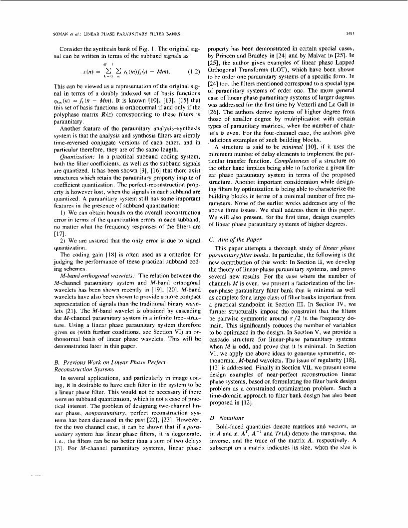
not clear from the context. Reserved symbols for special matrices are as follows: Z is the identity matrix. The ma- trix J N is the antidiagonal matrix of size N x N . For ex- ample, the antidiagonal matrix of size 4 is
0 0 0 1
J4 = [’ 0 1 0 0 ‘1. (1.3)
1 0 0 0
r o o o 11
L i o o OJ 0 will denote the null matrix, whose size will be clear from the context. V, will denote a special diagonal matrix of size K X K , with alternating +l’s on the diagonal, starting with + 1 .
A superscript asterisk as inf * (n) denotes conjugation. Consider a transfer function A ( z ) . It can be written in terms of its M polyphase components [27] as follows:
~ ( z ) = ao(zM) + z - ’ a l ( z M >
+ . . . + z - ( M - l ) a,+- I (zM). (1.4) This is known as Type I polyphase. Let H , ( z ) , i = 0, . . . , M - 1 , be a set of analysis filters. They can be written as
M - 1
Hk(z ) = C z - ‘Ek l ( zM) k = 0, * . * , M - 1 f = O
The matrix E ( z ) = [Ek, I (z)] is called the polyphase matrix of the analysis filters. A set of filters H k ( z ) whose poly- phase matrix is paraunitary are said to form a paraunitary system (1.1). Throughout this paper, we will deal with real, causal, and FIR systems. Given such a system E(z ) of order N , we can write it explicitly as
~ ( z ) = e(O) + e ( 1 ) z - ’ + e(2)z-’
+ . . . + e ( N ) z - N , e(N) # 0. (1.5)
The analysis filters typically have order M ( N + 1) - 1.
11. THEORY OF LINEAR PHASE PARAUNITARY SYSTEMS In order to obtain factorizations of linear phase parauni-
tary systems, we first need to obtain a characterization of their polyphase matrix which reflects the linear phase property of the individual filters. Consider a set of M paraunitary transfer functions whose polyphase matrix E ( z ) satisfies the property [26]
D Z - ~ E ( Z - ’ ) J M = E ( z ) (2.1) where N is the order of the paraunitary matrix E ( z ) . Such a polyphase matrix corresponds to a set of filters which have linear phase. The matrix D is a diagonal matrix whose entries are +l’s , the + l ’ s in those rows which correspond to symmetric filters and -1 ’s in those that correspond to antisymmetric filters. The filters described by this equation have the same center of symmetry ( ( N +
It is conceivable that there are linear phase paraunitam l ) M - 1)/2.
systems which cannot be characterized as in (2.1). One example is that of the “delay chain,” wherein the anal-
However as said earlier, obtaining factorizations requires us to impose constraints on the polyphase matrix of the filters, and (2.1) represents a large class of filter banks important from a practical standpoint. In this paper, we will consider only those systems that can be described by (2.1). We will also show several good design examples based on such systems.
The linear phase constraint in conjunction with the paraunitary property imposes interesting conditions on the filters. The paraunitary property implies orthonormality of the impulse response to its own shifted versions [IO], [15] and the linear phase property implies that the filters are time-reversed versions of themselves (upto a factor of + l ) . This, for example, imposes a restriction on the length of the filters.
Fact I : Let F, ( z ) be a set of M linear phase paraunitary filters of length L each with (0) # 0. Then, L # 1M + 1 for any integer 1 2 1 .
Pro08 The orthonormality condition on the filters [ 101 in particular implies,
ysis filters are simply H,( z ) = z-I, i = 0, * , M - 1 .
m
c f;(n) f?(n - 1M) = 6 ( i ) . (2.2)
If the length of the filters is L = 1M + 1 , in view of linear phase property this means that
(2.3)
implying that 6 (0) = 0. Hence the length L # IM + 1 0
The perfect reconstruction condition also imposes a constraint on the number of symmetric and antisymmetric functions in the filter bank. This is stated in the following theorem:
Theorem I : Consider a M-channel linear phase perfect reconstruction system.
1 ) If M is even, there are M/2 symmetric, and M/2 antisymmetric filters.
2) If M is odd, there are (M + 1)/2 symmetric and (M - 1)/2 antisymmetric filters.
This result has been proved in [28] for the special case where the order of the paraunitary matrix E ( z ) is one. The proof therein is based on subspace techniques, and more- over, does not extend to the case where E(z ) has an ar- bitrary order. The result has been stated explicitly as an assumption in [26]. We provide below a formal proof that this is indeed true. Note, that the result is not restricted to paraunitary filter banks.
Proof; Consider (2.1). The trace of the matrix D holds the key to the number of symmetric and antisym- metric filters in the system. Using the fact that the matrix E ( z ) is invertible, we have
n = -m
f ; (0)f;” (0) = 0
for any integer 1 I 1 .
Tr(D) = Tr(zNE(z)JME-I(z-’)) (2.4)
SOMAN er al . : LINEAR PHASE PARAUNITARY FILTER BANKS 3483
We have used the fact that Tr(AB) = Tr(BA). The left hand side of this equation is constant. Hence its value can be found by evaluating the right hand side for one value of the variable z . Putting z = 1 in the above equation we get,
Tr(D) = T r ( E - ' ( l ) E ( l ) J M ) = T r ( J M ) (2.6)
with the antidiagonal matrix J M as in (1.3). Therefore, it can be verified that Tr(D) = 0 if M is even, and Tr(D) = 1 if M is odd. Hence there are an equal number of symmetric and antisymmetric functions if M is even, whereas if M is odd, there is one extra symmetric function. 0
In particular, the above theorem implies that all the fil- ters cannot be zero phase. The proof of the above theorem also implies a interesting constraint on the order of the linear phase polyphase matrix E ( z ) when the number of filters M is odd.
Corollary 1: If the number of channels M is odd, the order N of the polyphase matrix E(z ) cannot be odd.
Pro08 Consider (2 .5) , and let N be odd. If one eval- uates the right hand side of this equation at z = -1 in- stead of z = 1, we get,
Tr(D) = T r ( ( - l ) N E - l ( - l ) E ( - l ) J M ) = - T r ( J M ) .
(2.7)
This, along with (2.6) would imply that T r ( J M ) = 0, but this is not possible since M is odd. Hence we get a con-
0 An interesting consequence of imposing the paraunitary
constraint on an M-channel filter bank is that it guarantees that if the first M - 1 filters are linear phase, the last filter is also linear phase. This is formally stated in the follow- ing theorem.
. . , M - 1 be paraunitary, and let the first M - 1 of them have linear phase. Then the last one is guaranteed to have lin- ear phase.
Before we prove the theorem we will prove a lemma which will help us in the proof.
Lemma 1: If M - 1 functions of a FIR paraunitary sys- tem are known, the last one is uniquely determined (upto a factor of the form (e">zlM).
Proof: Let F,(z) , i = 0, , M - 1 form a FIR paraunitary system. Let, if possible, U ( z ) be another FIR
forms a paraunitary system. Let E ( z ) , the polyphase ma- trix corresponding to this modified set of paraunitary functions, be partitioned as
tradiction, proving that N cannot be odd.
Theorem 2: Let a set of filters F,(z), i = 0 ,
. .
function, which along with F j ( z ) , i = 0, . . . , M - 2
This means that the row vector U ( Z ) has as its elements the polyphase components of the filter U ( z ) . Since E ( z ) is unitary on the unit circle, U (e'") is uniquely determined upto a scale factor of the form Hence, by analytic continuation, U ( z ) = A ( z M ) F M - ( z ) , where A ( z ) is all
pass. It can be verified that the condition det ( E ( z ) ) = delay, which is necessary for paraunitariness, implies that A ( z ) = (e je)z lM. Hence, given M - 1 functions of an FIR paraunitary system, the last function is determined upto a
I7 Using this lemma, we can now prove Theorem 2. Proof of Theorem 2: Let E ( z ) be a paraunitary poly-
phase matrix corresponding to a set of filters that have linear phase. Let E l ( z ) be the polyphase matrix of size (M - 1) x M corresponding to the first M - 1 filters in the system, and let U ( z ) be the row vector whose elements are the polyphase components corresponding to the last filter U ( z ) of the system. Now, (2.1) can be rewritten as
factor of the form ( e j ' ) ~ ' ~ .
This means that the row vector U (2) has as its element the polyphase components of the filter v(z ) , which is the time-reversed version of U ( z ) (upto f 1). Now, since all matrices on the left hand side of this equation are para- unitary, the matrix on the right hand side of this equation is also paraunitary. But the first block of this matrix is E l ( z ) . This means by Lemma 1, that v ( z ) = ~ z ' ~ u ( z ) . But since v(z ) is also the time-reversed version of the
0 filter U ( z ) , it implies that U ( z ) has linear phase.
111. FACTORIZATION OF LINEAR PHASE PARAUNITARY SYSTEMS FOR EVEN M
In this section, we will first derive a cascade-form structure for synthesizing linear phase paraunitary sys- tems. Our theory will provide an interpretation for the condition mentioned in [26]. We will then prove the main result of this section, namely, every linear phase parauni- tary system described by (2.1) can be factored in terms of the proposed structure.
The synthesis procedure consists of two steps. In the first step, we propagate the property that the set of filters generated be painvise time-reversed versions of one an- other. This means that they are related as h;(n) =
Notice that the sum of two sequences related as above is symmetric, and their difference is antisymmetric. Fur- thermore, any linear combination of symmetric (antisym- metric) sequences is symmetric (antisymmetric). In the second step, we add an orthogonal block which performs these operations on the pairwise symmetric sequences to obtain filters that have linear phase.
The reason for this two step approach is that, it can be shown that it is not possible to propagate the linear-phase property itself by addition of further building blocks.
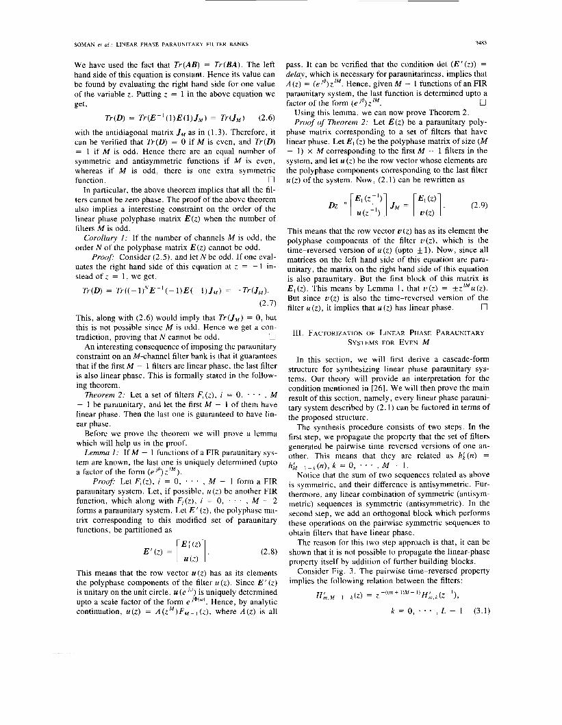
Consider Fig. 3. The pairwise time-reversed property implies the following relation between the filters:
hh- 1 -k(n) , k = 0, ' , M - 1.
H , ' M - I - k ( ~ ) = z - ( ( ~ + ' ) ~ - ' ) f f h , k ( z - ' ) ,
k = 0, * * , L - 1 (3.1)
3484 IEEE TRANSACTIONS ON SIGNAL PROCESSING, VOL. 41, NO. 12, DECEMBER 1993
H ; ,o (2) * c
K , L - I ( Z ) *
H :, L (z) z=M ~
- - Z -M
Z - M . - - Hm: M.l(Z)
+H :+I. o(z)
+Hm:I, L - ~ z )
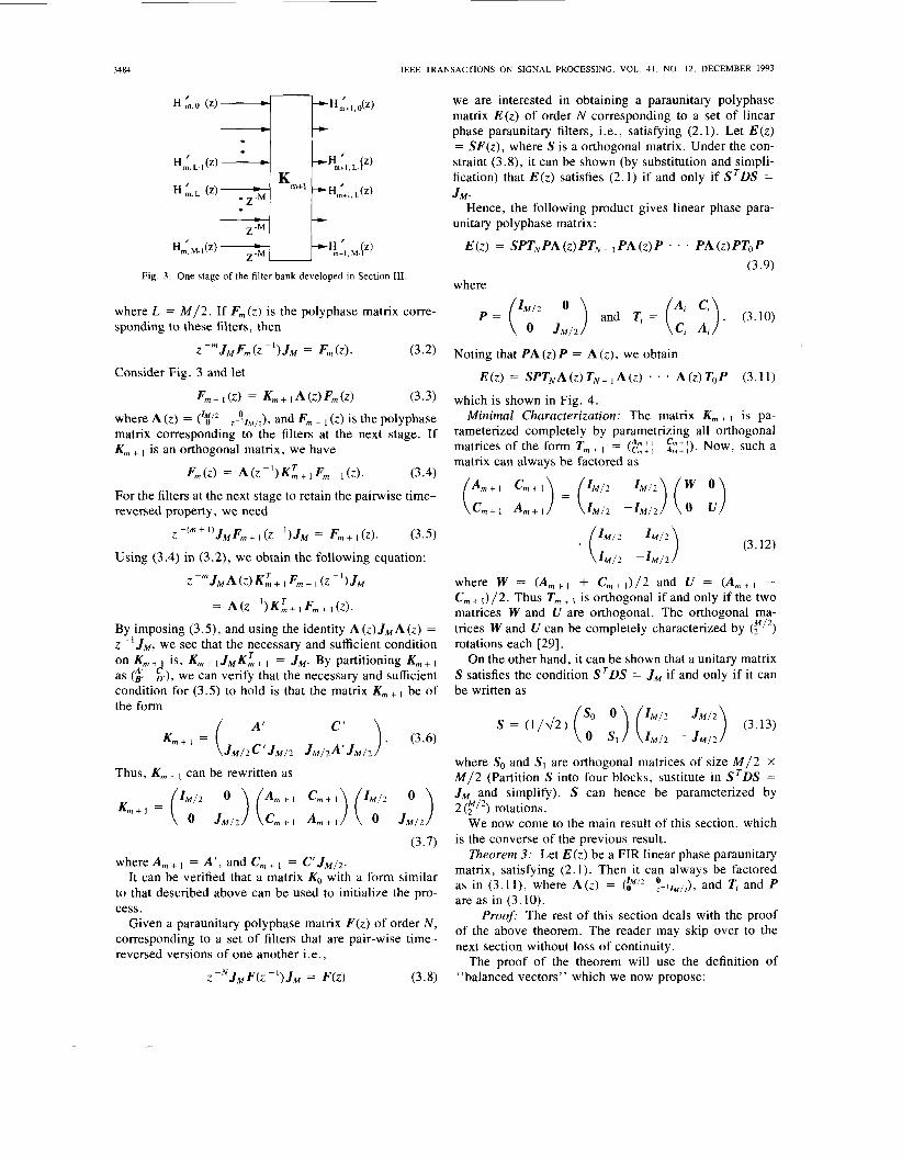
we are interested in obtaining a paraunitary polyphase
phase paraunitary filters, i.e., satisfying (2.1). Let E(z )
straint (3.8), it can be shown (by substitution and simpli-
matrix E ( z ) of order N corresponding to a set of linear
= SF(z ) , where S is a orthogonal matrix. Under the con-
fication) that E ( z ) satisfies (2.1) if and only if STDS =
Hence, the following product gives linear phase para-
+
H A , , L(z) JIM. Kmt -
+ unitary polyphase matrix:
E(z ) = SPTNPA (z) PTN - I P A (z) P . . . P A (z) PTO P a+!k:l, M p )
Z - ‘ ” ’ ’ J M F ~ + ~ ( Z - ’ ) J ~ = F,+~(Z). (3.5)
Using (3.4) in (3.2), we obtain the following equation: (3.12)
Z - m JM A ( Z ) K i + I F m + I ( Z - I > JM where W = ( A , + 1 + C,+,) /2 and U = ( A , + I - C, + /2. Thus T, + I is orthogonal if and only if the two matrices W and U are orthogonal. The orthogonal ma- trices Wand U can be completely characterized by ( ? I 2 ) rotations each [29].
On the other hand, it can be shown that a unitary matrix S satisfies the condition STDS = JM if and only if it can be written as
= A (Z - l ) K L + 1 F m + 1 (~1. By imposing (3.5), and using the identity A(z)JMA(z) = z - ’ J M , we see that the necessary and sufficient condition on K, + is, K, + J M K i + I = J M . By partitioning K, +
as ($ g), we can verify that the necessary and sufficient condition for (3.5) to hold is that the matrix K , + be of
so 0 the form
S = ( 1 / J 2 ) ( ) J M / 2 ) (3.13)
where So and S I are orthogonal matrices of size M/2 X M/2 (Partition S into four blocks, sustitute in S T D S =
“ ). (3.6) 0 SI I M / ~ - J M / ~ J M / ~ C ’ J M / ~ J M / z A ’ J M / Z
Km+l =
Thus, K, + can be rewritten as JM and simplify). S can hence be parameterized by
We now come to the main result of this section, which Km+l =
(3.7) is the converse of the previous result. \ I
Theorem 3: Let E ( z ) be a FIR linear phase paraunitary matrix, satisfying (2.1). Then it can always be factored as in (3.11), where A(z) = !- I~~,~), and T; and P are as in (3.10).
Proofi The rest of this section deals with the proof
where A , + = A ‘ , and C, + I = C’ JMI2. It can be verified that a matrix KO with a form similar
to that described above can be used to initialize the pro- cess.
corresponding to a set of filters that are pair-wise time- reversed versions of one another i.e.,
Given a paraunitary polyphase matrix F(z ) Of Order N , of the above theorem. The reader may skip over to the next section without loss of continuity.
The proof of the theorem will use the definition of z - ~ J M F ( z - ’ ) J M = ~ ( z ) (3.8) “balanced vectors” which we now propose:
SOMAN er al.: LINEAR PHASE PARAUNITARY FILTER BANKS 3485
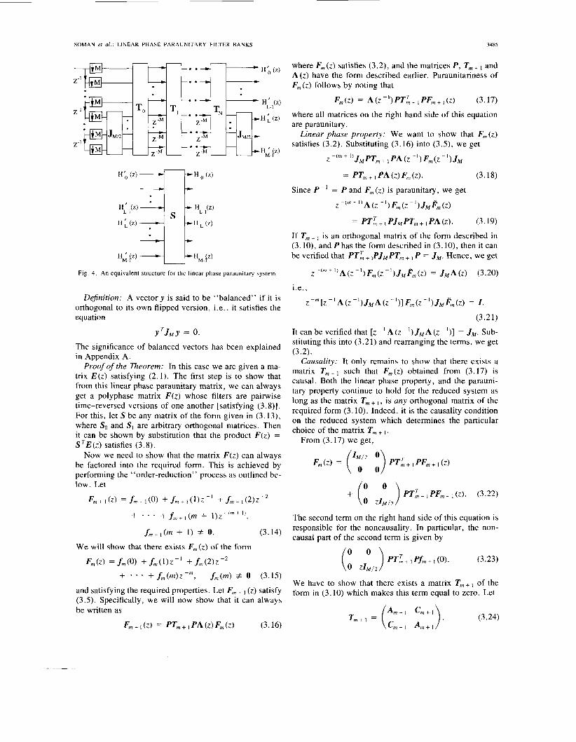
I I .
Fig. 4. An equivalent structure for the linear phase paraunitary system.
Dejnition: A vector y is said to be "balanced" if it is orthogonal to its own flipped version, i.e., it satisfies the equation
yTJMy = 0.
The significance of balanced vectors has been explained in Appendix A.
Proof of the Theorem: In this case we are given a ma- trix E(z ) satisfying (2.1). The first step is to show that from this linear phase paraunitary matrix, we can always get a polyphase matrix F ( z ) whose filters are pairwise time-reversed versions of one another [satisfying (3.8)]. For this, let S be any matrix of the form given in (3.13), where So and SI are arbitrary orthogonal matrices. Then it can be shown by substitution that the product F ( z ) = S T E ( z ) satisfies (3.8).
Now we need to show that the matrix F ( z ) can always be factored into the required form. This is achieved by performing the "order-reduction'' process as outlined be- low. Let
F,,, + 1 ( z ) = f m + I (0) + fm + I (1)z - I + f,,, + I (212 -* + . . . +f,,+1(m + l ) P + l ) ,
fm+I(m + 1) f 0. (3.14)
We will show that there exists F,,,(z) of the form
F,,,(z) = f m ( O > +f, , , ( l)z-I +f,,,(2)z-2
+f,,,(m>z-", f m ( m ) f 0 (3.15)
and satisfying the required properties. Let F,,, + (z) satisfy (3.5). Specifically, we will now show that it can always be written as
Fm + I (z) = PTm + 1 PA (z) Fm ( z ) (3.16)
+ . . .
where F,,,(z) satisfies (3.2), and the matrices P , T,,, + and A(z) have the form described earlier. Paraunitariness of F,,,(z) follows by noting that
Fm(z) = A W 1 ) P T ; + I PF, + ( z ) (3.17)
where all matrices on the right hand side of this equation are paraunitary .
Linear phase property: We want to show that F,,,(z) satisfies (3.2). Substituting (3.16) into ( 3 . 3 , we get
J M P T , , , + I PA(Z - I ) F,,,(z - 9 JM - ( m + 1 )
= PT, , ,+~PA(z )F , , , ( z ) . (3.18)
Since P-I = P a n d F,,,(z) is paraunitary, we get
z-(~+~)A(z-~)F,,,(z-~)J~F~(z) = PT;. ,PJ,PT, . ,PA(Z). (3.19)
If T,,, + is an orthogonal matrix of the form described in (3. lo), and P has the form described in (3. lo), then it can be verified that PT; + 1PJM PT,,, + P = JM. Hence, we get
(3.20) z - ( ~ + ' ) A ( z - I ) F,,, (Z - I ) JMFnl ( z ) = J M A ( z ) i.e.,
z -m [z A ( z - I ) J M A ( z -')I F,,(z - I ) JMF,,,(z) = I .
(3.21)
It can be verified that [ z A ( z - I ) J M A ( z - I ) ] = J M . Sub- stituting this into (3.21) and rearranging the terms, we get (3.2).
Causality: It only remains to show that there exists a matrix T,,,,, such that F,,,(z) obtained from (3.17) is causal. Both the linear phase property, and the parauni- tary property continue to hold for the reduced system as long as the matrix T,,, + I , is any orthogonal matrix of the required form (3.10). Indeed, it is the causality condition on the reduced system which determines the particular choice of the matrix T,,, + I .
From (3.17) we get,
The second term on the right hand side of this equation is responsible for the noncausality . In particular, the non- causal part of the second term is given by
We have to show that there exists a matrix T,,, + I of the form in (3.10) which makes this term equal to zero. Let
3486 lEEE TRANSACTIONS ON SIGNAL PROCESSING. VOL. 41. NO. 12. DECEMBER 1993
Simplifying (3.23), we find that T, + I should be such that
Hence, it is sufficient to find A , + I and C, + I such that
(C:+I A ~ + I J M / ~ ) ~ , + I ( O ) = 0. (3.26)
Now, (3.5) in particular means that
J M ~ ~ + I ( O ) J M = f m + i ( m + 1). (3.27)
The paraunitary condition in the time domain implies f f + (m + l)f, + I (0) = 0. Hence, we have
f I + I (0) JMfm + I (0) = 0. (3.28)
By Sylvester's rank inequality [30] therefore, we get r a n k ( f m + l ( 0 ) ) = r I M/2.
Equation (3.28) implies that the columns of the matrix f, + I (0) are balanced. Hence, it can be shown (Appendix B), that there exists a set of orthonormal balanced vectors x i , i = 1, * - * , M/2 such that if X T is the matrix of size M/2 X M whose rows are these vectors, this matrix sat- isfies the following properties:
1) X T X = Z M 1 2 (from the fact that x, are orthogonal). 2) X T J M X = 0 (from the fact that xi are balanced). 3) X T J M f m + (0) = 0 (by the construction outlined in
It can be verified that the matrix Appendix B).
can be written in the form as in (3.24). Moreover, with this choice of the matrix T, + I , (3.25) is satisfied. This proves that F, ( z ) is causal.
Order reduction: Given the fact that Fm(z) is causal, and that it satisfies (3.2), we can see that the order of F, ( z ) is m. Thus there is a reduction in order by 1. Hence, for a system of order N , the factorization process is guar- anteed to terminate in N steps.
0 The above theorem guarantees the factorization of all
linear phase paraunitary systems satisfying (2.1). Such a linear phase filter bank with polyphase matrix of order N can hence be characterized by 2 ( N ) (f'*) rotation angles.
The degree of a causal rational system is defined as [ 10, sec. 13.81 the minimum number of delays required for its implementation. A structure is said to be minimal if the number of delays used is equal to the degree of the trans- fer function. For a paraunitary system, we know that [ lo ,
This concludes the proof of Theorem 3.
Theorem 14.7.11 that
deg [det [E(z) l l In our case,
deg [det [ E ( z ) ] ] = deg [det
. A(Z)
= deg [ E ( z ) l . (3.30)
which is equal to the number of delays used. Hence, the factorization is minimal.
IV. LINEAR PHASE PARAUNITARY FILTERS WITH
RESPONSES FOR EVEN M In the previous section, we factorized a linear phase
paraunitary system into a product of orthogonal building blocks each of which can be implemented with 2 (r/2) ro- tation angles. These angles can be made the variables in the design process. The number of angles can be become fairly large when the number of channels M increases. It would be useful to cut down the number of optimization variables by structurally imposing some other additional constraints on the filters. One of the constraints that can be imposed is that of painvise mirror image symmetry in the frequency domain around ~ / 2 . Such a condition had been imposed on general paraunitary systems in [31]. One way to impose the condition that the filter satisfy the pair- wise mirror image condition in the frequency domain is to ensure that the filters are related as
PAIRWISE MIRROR-IMAGE FREQUENCY
H,+- 1 - k ( Z ) = H k ( - Z ) , k = 0, * * * , L - 1 (4.1)
where L = M/2. If M is even, in terms of the polyphase matrix of the filters this becomes
J,ME(z) = E ( z ) V M . (4.2)
As mentioned earlier, the matrix VM is a diagonal matrix of size M x M with alternate k 1's on the diagonal, start- ing with + 1. This symmetry condition is in addition to the conditions of linear phase (2.1) and paraunitariness (1.1).
To develop a cascade structure which generates such filters, we will assume that we have a paraunitary matrix E, - ( z ) of order m - 1 satisfying the conditions of para- unitariness (1. l ) , linear phase (2.11, and painvise mirror- image symmetry of frequency responses (4.2). From it, we will show how a paraunitary matrix E,(z) of order m can be obtained satisfying the above three properties. We will do this by post multiplying the given matrix E, - ( z ) by a paraunitary matrix R ( z ) of order one.'
Let
Em ( z ) E m - I ( z ) R ( z ) . (4.3)
E, - I ( z ) = E,n ( z ) R (4.
Clearly, E,(z) is paraunitary. Also,
(4.4)
Propagating the Linear Phase Property: From the fact that E, - I ( z ) satisfies the linear phase property, we have
z p m DE, ( z - I ) ( z - I ) JIM = E, ( z ) ( z ) (4.5)
'This derivation could also be made by premultiplying an existing matrix by an extra block. This was the approach followed in Section 111, because it simplifies the proof of Theorem 3 to some extent. In proving the results of this section, the postmultiplication strategy will lead to slightly simpler derivations. The reader must note that preference for one strategy over the other has been dictated purely by simplicity of presentation.

SOMAN et a l . : LINEAR PHASE PARAUNITARY FILTER BANKS 3487
i.e., of the form
z p m DE,,, (Z - 7 R (Z - 9 J M R (z) = E,, (z) . (4.6) S = ( l / & ) ( so 0 ) (": J''2) Q (4.14)
Hence for E,,, ( z ) to satisfy the linear phase property, R ( z ) 0 SI I M / ~ - J M / z ~. .
should satisfy where Q is a symmetric permutation matrix. This is be- cause QJMQ = JM for any such permutation matrix. Let Q be so chosen that QVMQ = D , where D = (?:? -IM,2). Now, let S ' = SQ. For the matrix S to sat- isfy the painvise mirror-image property ( J M S = SVM), it can be verified that the matrix S ' should satisfy S ' DS I T
= JM. Substituting the forms of various matrices and sim- plifying, we get
I ? ( z - ' ) J ~ R ( z ) = z - I J M . (4.7)
It can be verified that if Riz) = A ( z ) PTP with the ma- trices A ( z ) , P and T as in the previous section, R(z ) sat- isfies (4.7).
Propagating the Painvise Mirror-lmage Property in the Frequency Domain,, Assuming that (4.2) holds for E,,, - I ( z ) , and using (4.4) we get
J M E,,, (z) ( z ) E,,, (2) R ( z ) VM (4.8)
JM E, ( z ) = E,, ( z ) (z) VM R ( z ) . (4.91
i.e.,
Hence, R(z) should satisfy the property
R(z) VMR(z) =z VM. (4.10)
We now have two cases: Case I : M / 2 is even: In this case, VM = (K" ' "v,,?).
Substituting this, and the fact that R(z) = A ( z ) P T P with T = (c :), in (4.10) and simplifying, we get
AT C T
(c' A T ) ('y2 -;,,*) (t z) (4.11)
Using a factorization for T similar to (3.12) and simpli- fying, we get
The above equation is satisfied if U is taken to be an ar- bitrary orthogonal matrix of size M / 2 X M/2, and the matrix W is chosen as
w = v M / 2 UVM ' 2 . (4.13)
Hence, in this case, we have ( F / 2 > degrees of freedom to optimize per stage.
Case 2: M/2 is odd: In this case, VM = (0"";' o v M l 2 ) , unlike the case where M/2 is even. How- ever, if we use the relation R(z ) = A(z) PTP with T = (i ,"), and perform the simplifications as before, we get (4.12) once again, proving that there are (Y l2) degrees of freedom to be optimized in this case also.
Thus, all three properties have been satisfied. Initialization: It only remains to find a degree zero
paraunitary matrix E o ( z ) (i.e., a constant orthogonal ma- trix s), which will initialize the above process. From the discussion in Section I11 it can be verified that the matrix S satisfies the linear phase property (DSJM = S ) , if it is
This equation can be satisfied by letting So be an arbitrary orthogonal matrix, and choosing SI = J M / 2 S o . Thus the matrix S can be realized with ( y / 2 ) rotations 1291.
The foregoing discussion can be summarized in the fol- lowing theorem :
Theorem 4: A linear phase paraunitary matrix satisfy- ing (2.1) whose filters satisfy the additional painvise mir- ror-image property in the frequency domain (4.2) can be realized as
E ( z ) = SA(z)PTUA(z) . . . TNP (4.16)
where
(4.18)
and the matrix P is as in (3.10). 0 The fact that the structure continues to be minimal is
easily verified, though we have not shown it to be com- plete.
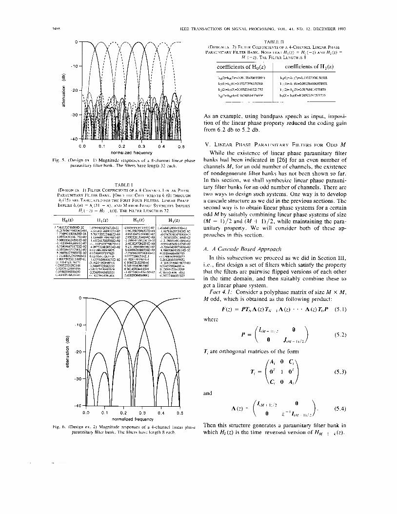
Fig. 5 shows an example of a 8-channel system (Design ex. 1) where a 4-stage lattice was used. The filters are linear phase, paraunitary , and satisfy the painvise mirror- image symmetry in the frequency domain. The impulse response coefficients of the 8-channel system have been tabulated in Table I . Fig. 6 shows a similar example for the 4-channel case (Design ex. 2). The impulse response coefficients have been tabulated in Table 11.
The coding gain [ 181 is often used as a figure of merit to judge the performance of various subband coding schemes. It is defined as the ratio of the reconstruction error variance of a PCM system to the reconstruction error variance of the subband coding system. It was verified through examples that the imposition of linear phase property did not lead to significant coding gain reduction.
3488 IEEE T R A N S A C T I O N S O N S I G N A L P R O C E S S I N G , VOL. 41, N O . 12. DECEMBER 1993
-30
- 4 0
0.0 0.1 0.2 0.3 0 . 4 0 .5 normalized frequency
Fig. 5 . (Design e x . 1 ) Magnitude responses of a 8-channel linear phase paraunitary filter bank. The filters have length 32 each.
TABLE 1
PARAUNITARY FILTER BANK. [ONLY THE C O E F F I C I E N T S h, (0) THROUGH
I M P L I E S h , ( n ) = h , ( 3 1 - n). A N D MIRROR-IMAGE S Y M M E T R Y IMPLIES
(DESIGN E X . 1) FILTER COEFFICIENTS OF A %CHANNEL L I N E A R PHASE
h , ( 1 5 ) ARE TABULATED FOR THE FIRST FOUR FILTERS. L I N E A R PHASE
H , ( - z ) = H , , ( ? ) I . THE FlLrER LEUGTH IS 3 2
-2.8456950643002D-02 I m 9 s n 3 ~ m w ~ - o 3 4.0561 84s27nnm~-o2 2.950320193466OD-03
-2.2991473562361D-02 3.401 8237002281D-03
8.6349676608556D-03 9.231 1 9 n 4 1 a m ~ - 0 2
-7.7589420570n20~-02 ~ll.2277206631421 1 -0.19287393785391 0.10867205234840 0.34879540903907 030145304416569 ~3.4833482443945D-02
-0.40W59004960062
I .4~60492098433~-02 4.46781628754690-02 -4 0347878743950D-03 -1 2928325761109D-02 -1 51098R1590786D-02 -4.94448345 I6 179D-02 -3.7266345907583D-02
01 1 I866646696795
4 .26 I241 85969832 -1 3044768601487D-03
~ . ~ m 8 o 4 o s I M D - ~
-0.10980a19unn73
0.37437930463n34 0 . 1 ~ 0 9 u i 2 ~ 3 2 n 9 -0 38952044617052 ~0.292274ho35.5523
TABLE I1
PARAUNITARY FILTER B A N K . NOTE THAT Hi ( 2 ) = Ho ( -I) A N D H2 ( z ) =
H, ( - z ) . T H E FILTER LENGTH IS 8
(DESIGN E X . 2) FILTER COEFFlCltNTS O F A 4-CHANNEL LINEAR PHASE
coefficients of Ho(z)
ho(O)=hd7)=-0 091 58480695895 1
ho(1 )=h0(6)=0. I3357390156568
hg(2)=hg(S)=O 38923341521735
h0(3)=h0(4)=0 567686 I4376856
coefficients of H (z)
h I(0)=-hl (7)=-0.13357390156568
h 1(1 I=-h ~(6)=O.o9158480695895l
h 1(2)=-h I (5)=0.56768614376856
h 1(3)=-h 1(4)=0.38923341521735
As an example, using bandpass speech as input, imposi- tion of the linear phase property reduced the coding gain from 6.2 db to 5.2 db.
V . LINEAR PHASE PARAUNITARY FILTERS FOR ODD M While the existence of linear phase paraunitary filter
banks had been indicated in [26] for an even number of channels M , for an odd number of channels, the existence of nondegenerate filter banks has not been shown so far. In this section, we shall synthesize linear phase parauni- tary filter banks for an odd number of channels. There are two ways to design such systems. One way is to develop a cascade structure as we did in the previous sections. The second way is to obtain linear phase systems for a certain odd M by suitably combining linear phase systems of size ( M - 1)/2 and ( M + 1)/2, while maintaining the para- unitary property. We will consider both of these ap- proaches in this section.
A . A Cascade Based Approach In this subsection we proceed as we did in Section 111,
i .e., first design a set of filters which satisfy the property that the filters are painvise flipped versions of each other in the time domain, and then suitably combine these to get a linear phase system.
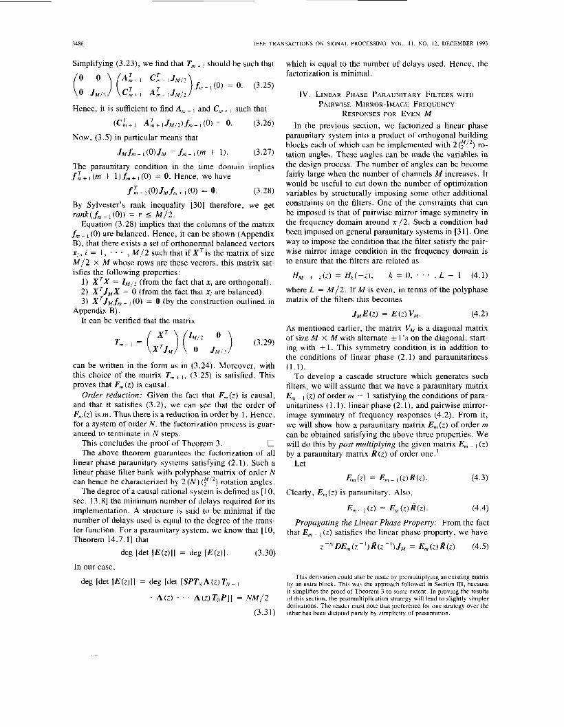
M odd, which is obtained as the following product: Fact 4 .1: Consider a polyphase matrix of size M x M ,
0
F(z) = P T N A ( z ) T , ~ - , A ( z ) * * A(z)TOP (5.1)
where -10
k M + I i / 2 z P = ( v U 0 J w - 1 ) / 2
.; -20 TI are orthogonal matrices of the form
- - A; 0 C, T, = OT 1 0'
-30 ( C i 0 A )
C
3 c
m
and
O ) . (5.4) 4 M + 1 ) / 2
-I 0 z z ( M - 1) /2
Then this structure generates a paraunitary
- 4 0 A ( z ) = 0.0 0.1 0.2 0.3 0.4 0.5
normalized frequency
Fig. 6 . (Design e x . 2) Magnitude responses of a 4-channel linear phase bank in paraunitary filter bank. The filters have length 8 each. which Hk ( z ) is the time-reversed version of HM - - ( z ) .
(5.3)
SOMAN er al.: LINEAR PHASE PARAUNITARY FILTER BANKS 3489
Pro05 Since all matrices in the product are individ- ually paraunitary , the product F(z) is also paraunitary . Now to prove that the filters are pairwise flipped versions of one another, we need to show that the matrix F(z) sat- isfies the condition ( z-Nz!-l)/2 0
1 ,9 ) J M F ( Z - N ) J M = F(z)
z -"4M - 1)/2
( 5 . 5 ) where N is the order of the polyphase matrix F(z). In par- ticular, by our construction, the middle filter will be just H ( M + (2) = z - ( M + Hence, it is the flipped version of itself. Substituting the forms of various matrices, we
0 Now suppose we are given a paraunitary matrix F(z)
satisfying (5.5) and whose order N is even (as required by Lemma l ) , we can obtain a matrix E ( z ) from it which corresponds to a set of linear phase paraunitary filters. Since the middle filter is just H(M+ ,)/2(z) = z - ( ~ + ' ) / ~ , we first multiply this filter by an appropriate delay z This can be done by premultiplying the matrix F(z) by the diagonal matrix A (z) = diag[l 1
- 1 13 to get F ' ( z ) = A'(z)F(z) . The matrix F' (z) hence satisfies the equation
can verify that (5.5) indeed holds.
- - z-N/2 *
z - ~ J ~ F ' ( z - ' ) J ~ = ~ ' ( z ) . (5.6) Now let E(z) = S F ' ( z ) where S is an orthogonal ma-
trix. Clearly, with this construction, the matrix E(z) is
7'heorem 5: A linear phase paraunitary matrix with an odd number of channels can be realized as
E(z) = SA'(Z)PTNA(Z)TN-IA(Z) * * TOP (5.8)
(5.4). 0 where P is as in (5 .2) , T, is as in (5 .3) and A(z) is as in
The fact that the structure is minimal can be verified as at the end of Section 111.
B. Matrix Interleaving and Linear Phase Filters In this subsection, we will consider the problem of ob-
taining a larger linear phase paraunitary system given smaller linear phase paraunitary systems. Let M , the num- ber of channels be odd. Let L = ( M - 1 ) / 2 . Let G(z) and F ( z ) be two linear phase paraunitary matrices of sizes (L + 1) X (L + 1) and L X L respectively, and of order N each. In particular, let us write them as
and
F(z) = (fo(z) fl (z) . * fL - 2(2 ) fL - 1 (4). (5.10)
In (5.9), the vectors g i ( z ) are of size L, and represent the columns of the matrix G(z), except for the last element in each column, which has been written separately as g / (z). In (5. l o ) , the vectorsJ.(z) are also of size L, and are sim- ply the columns of the matrix F(z). Hence note that vec- tors gi(z) andJ(z) are all of size L each. Now, construct the matrix E(z) of size M x M , which is as follows:
also paraunitary . For the matrix E (2) to satisfy the linear phase property (2. l ) , it can be verified that it is both nec- essary and sufficient that S be of the form
where U(M+ 1) /2 and W ( M - 1 ) / 2 are arbitrary orthogonal matrices of the sizes indicated.
The above discussions can be summarized in the fol- lowing theorem:
Note that the filters corresponding to this polyphase ma- trix are formed simply by interleaving in a particular man- ner the impulse response coefficients of the filters in the smaller systems G ( z ) and F(z).
Lemma 2: The matrix E(z) of size M x M in (5 .11) is a linear phase paraunitary matrix of order N .
Proof: The fact that E(z) is paraunitary is clear from the construction. It only remains to prove the linear phase property. Because the matrices G(z) and F(z) are linear phase, we have the following relations
g, (z) = +z + g L - , (z -9, (5.12)
J(Z> = *z-NfL-I-I(Z-l) (5.13)
and
g:(z) = +z-Ngt- , (Z- ' ) . (5.14)

3490 IEEE TRANSACTIONS ON SIGNAL PROCESSING, VOL. 41, NO. 12, DECEMBER 1993
1
/ - I
E = structure giving linear-phase paraunitary filters for even M X= the interleaving mechanism
Fig. 7 . Obtaining linear phase paraunitary filters by interleaving smaller systems.
Let e , ( z ) denote the columns of the matrix E(z ) . Then, it can be seen from the construction of the matrix E ( z ) that the columns satisfy the condition
e j ( z ) = k z - N e M - I - i ( z - l ) . (5.15)
This is sufficient to prove that E ( z ) has linear phase filters. U
Lemma 2 gives us a way to synthesize larger parauni- tary systems from smaller ones. Thus, one can obtain a M channel linear phase paraunitary filter bank by using a schematic as shown in Fig. 7. Here, Lemma 2 is repeat- edly used to synthesize the odd component on each level.
VI. M-BAND ORTHONORMAL WAVELETS The wavelet transform [32]-[34], [13] is a representa-
tion of a signal in terms of a set of basis functions which are obtained by dyadic dilations and shifts of a single function called the wavelet function. It provides a de- scription of a signal on various levels of resolution or scale. The wavelet transform has of late, found several applications in signal and image processing [34], [35]. One way of constructing the wavelet functions that gen- erate a basis [32] is by using a two-channel quadrature- mirror filter bank is an infinite tree. This idea of wavelets (henceforth referred to as dyadic wavelets) has recently been extended to the more general case of M-band wavelets [19], [20], [36]. It has been shown therein that a square integrable function f( t ) can be represented in terms of the dilates and translates of M - 1 functions +,(t), which are called the M-band wavelets. As in the case of dyadic wavelets, it has been shown [20] that M-band wavelets can be obtained by using a M-channel filter bank system in a infinite recursive tree-structure as shown in Fig. 8. M-band wavelets often provide a more compact representation of signals, and are therefore use- ful in several applications [2 13.
It can be shown [20], that for the wavelet basis to be orthonormal, a necessary condition is that the M-channel filter bank used in Fig. 8 should be paraunitary. The the- ory developed in the previous sections allows us to design symmetric and antisymmetric wavelets that are also or- thonormal. This can be done simply by using the structure developed in Section I11 to generate the M-channel system
1 Ho(Z) tM II
I ,
Fig. 8 . A tree-structure using M-channel filter bank
on each level of the tree. Consider the quantity
*,(U> = (l/&)Hj(ejw/M) K
lim n (l/&)Ho(e'"(M)-k) (6.1) I K A m k = 2
where Ho(eJ") is a rational (in fact FIR) filter. This con- verges pointwise for all U as long as (H,(ej")( I & and HO(ejo) = &. For the linear phase paraunitary system developed in Section 111, the filters can be written as ~ , ( ~ j w ) = e -AN- l ) w / 2 HiR(u) , where HjR (U) is the real part of Hi(ei"), and we have
(1 / JM) HiR(U) = e - j ( N - l ) w ( M - ' + M-*+. ' . ) / 2
K
lim ]II ( l / & ) H O R ( ~ ( M ) - k ) (6.2) ~ - t m k = 2
which becomes
This is the Fourier Transform of an M-band wavelet func- tion and has linear phase.
Convergence, Orthonormality and Regularity [32]: The RHS in (6.1) always converges pointwise as long as (Ho(eiw)I 5 &, and Ho,(ejo) = &. In the paraunitary case, if the filter Ho(eJ") has no zeros in the range [ - a / M , 7 r / M ] , then convergence is also in the & sense, and the resulting continuous time functions form an or- thonormal basis for L2. The orthonormal family is Mk/2*ki(Mkt - l ) , i = 1 , 2 , 3. These facts can be derived by extending the two-channel results of [37], [39].
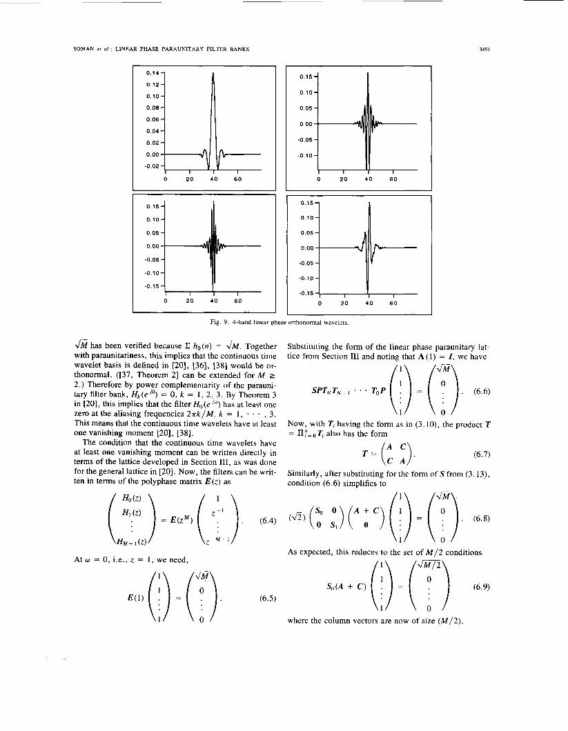
Fig. 9 shows an example of 4-band orthonormal, linear phase wavelets and their associated scaling function. For this example, the lattice developed in Section IV was used, and the filters were of length 80 each. Ho(e iw) was chosen such that it did not have any zero in the range [ - r / M , n /M] . Furthermore, in the example, Ho(eio) =
SOMAN er al.: LINEAR PHASE PARAUNITARY FILTER BANKS
0.14-
0.12-
0.10-
0.08 - 0.06 - 0.04 - 0.02 - 0.00
-0.02 -
349 I
IL I I I
0.15-
0.10-
0.05 - 0.00
-0.05 - -0.10-
-0.15 -
0 2 0 4 0 60
I 0 2 0 4 0 6 0
0 20 4 0 60
0 2 0 4 0 60
Fig. 9 . 4-band linear-phase orthonormal wavelets.
& has been verified because C ho(n) = fi. Together with paraunitariness, this implies that the continuous time wavelet basis is defined in [20], [36], 1381 would be or- thonormal. ([37, Theorem 21 can be extended for M 2 2.) Therefore by power complementarity of the parauni- tary filter bank, Hk(eJo) = 0, k = 1 , 2, 3. By Theorem 3 in [20], this implies that the filter Ho (e I") has at least one zero at the aliasing frequencies 27rk/M, k = 1, * * , 3 . This means that the continuous time wavelets have at least one vanishing moment [20], [38].
The condition that the continuous time wavelets have at least one vanishing moment can be written directly in terms of the lattice developed in Section 111, as was done for the general lattice in [20]. Now, the filters can be writ- ten in terms of the polyphase matrix E ( z ) as
At w = 0, i.e., z = 1 , we need,
Substituting the form of the linear phase paraunitary lat- tice from Section I11 and noting that A ( l ) = I , we have
Now, with Ti having the form as in (3. lo), the product T = II := Ti also has the form
T = (: :). (6.7)
Similarly, after substituting for the form of S from (3.13), condition (6.6) simplifies to
As expected, this reduces to the set of M / 2 conditions
where the column vectors are now of size ( M / 2 ) .

3492
I
IEEE TRANSACTIONS ON SIGNAL PROCESSING, VOL. 41, NO. 12, DECEMBER 1993
8-channel NPR filter bank design (aliasing = -75 12db) _II
normalized frequency
Fig. 10. (Design ex. 3) 8-channel NPR filter bank design (aliasing = -75.12 db).
Recall that SO can be chosen to be an arbitrary orthog- onal matrix for the factorization in Section 111. If we fur- ther wish to impose the condition (6.5), then we can ex- ploit this freedom in the choice of S O , and choose it so as to satisfy (6.9). It can be verified that the vector post- multiplying the matrix So in 6.9 has norm @. Given any vector of norm m, there exists a Hauseholder
matrix Z - 2uut which turns the vector into (-:)'."I,
0
[ l o , pp. 7511. So there always exists an SO satisfying (6.9).
VII. NEAR PERFECT RECONSTRUCTION LINEAR PHASE DESIGN
The theory developed in the previous sections ap- proaches the problem of designing linear phase parauni- tary systems via structurally imposing the constraints on the filter bank. This results in factorizations of the poly- phase matrix. Another approach to designing these filter banks is to formulate the problem as a constrained opti- mization problem. While the resulting systems do not have perfect reconstruction, they are very close to being perfect reconstruction systems. In this section, we present a de- sign method to obtain the so-called near-perfect-recon- struction (NPR) linear-phase filter banks. The NPR filter banks have some small amplitude distortion and aliasing, however, as we will see, they have high stop-band atten- uation. This makes them useful in applications where small distortions can be tolerated. Let Hk(z) and Fk(z) be the analysis and synthesis linear-phase filters (lengths L) of a M-channel linear-phase filter bank, respectively. The synthesis filters are chosen to be Fk(z) = z ( ~ - ' ) H ~ ( z - ' )
= Jk Hk(z) , where Jk is 1 (or - 1) for symmetric (or a_nti- symmetric) analysis filters. The reconstructed output X ( z ) is
In a perfect-reconstruction system, it is required that TO and Tl(z) = 0 for 1 # 0. Define the error func- = - ( L - 1)
tion el ( z ) to be the difference between TI ( z ) and its desired functions, i.e.,
then the objective of the NPR design method is to choose Hk ( z ) such that el ( z ) approximate 0. Moreover, Hk ( z ) must also have good frequency responses. Define the following objective function:
M - 1 M - 1
where (Yk are the weights (chosen by the user) and + k are the stopband energies of H k ( e J w ) . Similarly, P I are the
SOMAN er al . : LINEAR PHASE PARAUNITARY FILTER BANKS
0 1 2 3 4 5 6 7
3493
-5.54447264221553 - 04 1,98396953927873 - 05 1.03311851347463 - 03 3.12532018313433 - 03 3.2525521320976E - 03
-1.60210914628623 - 03 -1.01399910222293 - 02 -1.46573535208193 - 02
2.37717218282813 - 04 -1.43830782277933 - 03 2.20536903762123 - 04
-8.79720778580633 - 04 5.41519975280593 - 03 2.73817419369653 - 03
-2.22018016165513 - 02 1.45308115459053 - 02
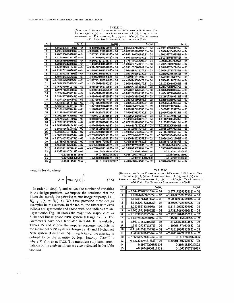
TABLE I11
FILTERS h,(n), h,(n), . . . ARE SYMMETRIC WHILE h , (n), h, (n) , . . . ARE
ANTISYMMETRIC. FURTHERMORE, h, - (n) = (- l ) " h , ( n ) . THE ALIASING IS
-75 .12 db. THE STOPBAND ATTENUATION IS -63 db
(DESIGN E X . 3) FILTER COEFFICIENTS OF A 8-CHANNEL NPR SYSTEM. THE
n W n ) I W n ) I hr(n) I
8 9 10
weights for $,, where
PI = / m y eI(n)12. (7.5)
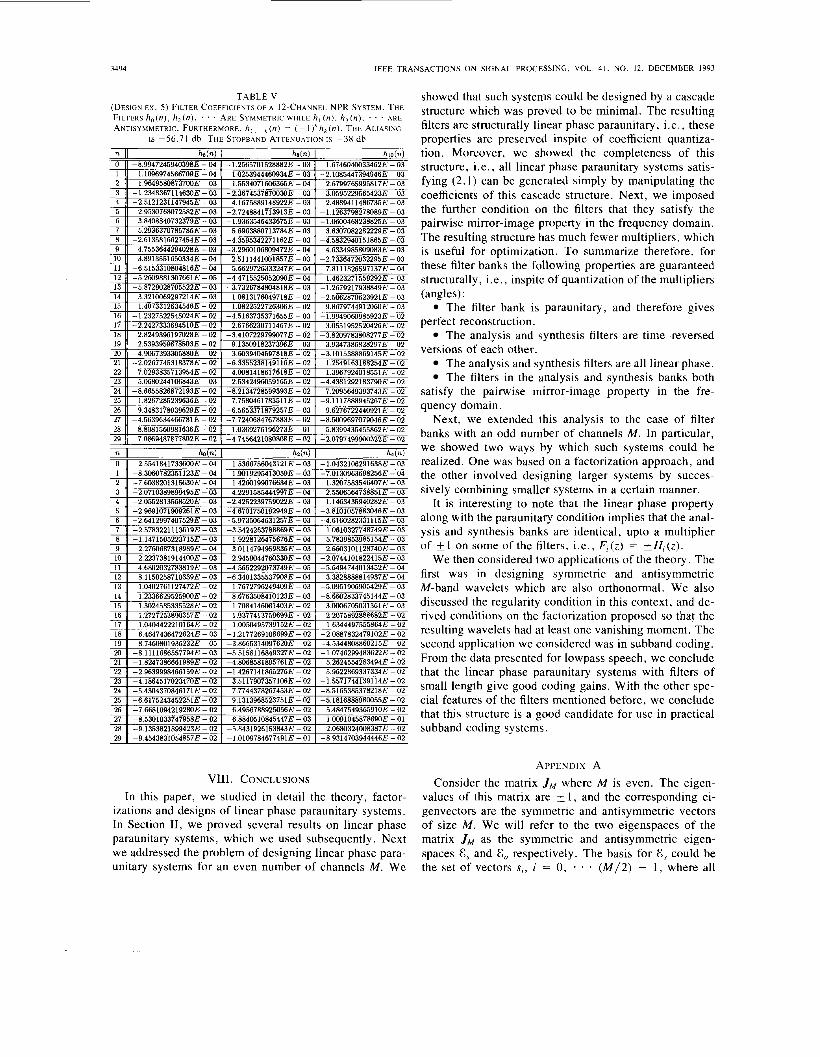
In order to simplify and reduce the number of variables in the design problem, we impose the condition that the filters also satisfy the painvise mirror image property, i.e., HM- , - k ( z ) = H k ( - 2 ) . We have provided three design examples in this section. In the tables, the filters with even indices are symmetric and those with odd indices are an- tisymmetric. Fig. 10 shows the magnitude response of an 8-channel linear phase NPR system (Design ex. 3). The coefficients have been tabulated in Table 111. Similarly, Tables IV and V give the impulse response coefficients for 4-channel NPR system (Design ex. 4) and 12-channel NPR system (Design ex. 5). In each table, the aliasing is defined to be the quantity 20 log,, [max,,/ IT,(e'")l], where T,(z) is as in (7.2). The minimum stop-band atten- uations of the analysis filters are also indicated in the table captions.
-5,86317261340283 - 03 1.74712723743473 - 02 4.1 126463410573E - 02
1.11239874485486 - 02 1.49065187461966 - 03
-7.9151202613239E - 03
TABLE IV
FILTERS h , ( n ) , h,(n) ARE SYMMETRIC WHILE h , ( n ) , AND h,(n) ARE
ANTISYMMETRIC. FURTHERMORE, h , - r ( n ) = ( - l ) " h p ( n ) . THE ALIASING I S -70.97 d b . THE STOPBAND ATTENUATION IS -59 db
(DESIGN EX. 4) FILTER COEFFICIENTS OF A 4-CHANNEL NPR SYSTEM. THE
n II ho(n) I ~ - hzln)
3.96062125517253 - 02 -7.86712692717113 - 02 0.13152350759896
-9.78733107437753 - 02 4.32201169243693 - 02 -0.1997629635921 6 -0.26641530036823
15 -0.26742606716914 0.16653767332615
3494 IEEE TRANSACTIONS ON SIGNAL PROCESSING. VOL 41. NO. 12. DECEMBER 1993
n 0 1
TABLE V
FILTERS h,(n), h z ( n ) , ’ . ’ ARE SYMMETRIC WHILE h , (n), h , ( n ) , . . ’ ARE (DESIGN EX. 5) FILTER COEFFICIENT’? OF A 12-CHANNEL NPR SYSTEM. THE
ANTISYMMETRIC. FURTHERMORE, h , , ~I (n) = ( - l )”h, (n). THE ALIASING IS -56.71 db. THE STOPBAND ATTENUATIOV I S - 3 8 db
h6(n) h d n ) hio(n) -8.99472459403986 - 04 -1.25657015288826 - 03 1.67460400334626 - 03
1.10969745667096 - 04 1.0253944460934E - 03 -2.10854473949466 - 03 2 1.96495808737003 -03 I 1.55340716063656 - 04 2.67997659958173 - 03
26 9 34831780396’296 - 02 27 -4 5639634466781E - 02 28 -8 d0815609816363 - 02
-6 565%?71879257E - 03 -7 7240684767883E - 02
10369276196273E - 01
9.6276722440921E - 02 -8.W969707904GE - 02
5.839943.5455862E - 02
17 11 1 04044222101646 - 02 I 1 00544957391523 - 02 I 1 63444975558646 - 02
n h o ( 4 I h d n ) I h s ( 4
VIII. CONCLUSIONS In this paper, we studied in detail the theory, factor-
izations and designs of linear phase paraunitary systems. In Section 11, we proved several results on linear phase paraunitary systems, which we used subsequently. Next we addressed the problem of designing linear phase para- unitary systems for an even number of channels M . We
13 14 15
showed that such systems could be designed by a cascade structure which was proved to be minimal. The resulting filters are structurally linear phase paraunitary , i.e., these properties are preserved inspite of coefficient quantiza- tion. Moreover, we showed the completeness of this structure, i.e., all linear phase paraunitary systems satis- fying (2.1) can be generated simply by manipulating the coefficients of this cascade structure. Next, we imposed the further condition on the filters that they satisfy the pairwise mirror-image property in the frequency domain. The resulting structure has much fewer multipliers, which is useful for optimization. To summarize therefore, for these filter banks the following properties are guaranteed structurally, i.e., inspite of quantization of the multipliers (angles) :
The filter bank is paraunitary, and therefore gives perfect reconstruction.
The analysis and synthesis filters are time-reversed versions of each other.
The analysis and synthesis filters are all linear phase. The filters in the analysis and synthesis banks both
satisfy the pairwise mirror-image property in the fre- quency domain.
Next, we extended this analysis to the case of filter banks with an odd number of channels M . In particular, we showed two ways by which such systems could be realized. One was based on a factorization approach, and the other involved designing larger systems by succes- sively combining smaller systems in a certain manner.
It is interesting to note that the linear phase property along with the paraunitary condition implies that the anal- ysis and synthesis banks are identical, upto a multiplier of f l on some of the filters, i .e., F, ( z ) = fHj(z).
We then considered two applications of the theory. The first was in designing symmetric and antisymmetric M-band wavelets which are also orthonormal. We also discussed the regularity condition in this context, and de- rived conditions on the factorization proposed so that the resulting wavelets had at least one vanishing moment. The second application we considered was in subband coding. From the data presented for lowpass speech, we conclude that the linear phase paraunitary systems with filters of small length give good coding gains. With the other spe- cial features of the filters mentioned before, we conclude that this structure is a good candidate for use in practical subband coding systems.
1,0402761 127472E - 02 I 1 23366295259001? - 02 I 1 302458533%)2RE - 02 I
I 7672796249409E - 03 8 67635O8410123/..’ - 03 I 7084146061403.E - 02
-5 095190690X)TA29E - 03 -8 66028337451446‘ - 0 3
3 0006705031361 E - 03
APPENDIX A Consider the matrix J,,, where M is even. The eigen-
values of this matrix are k 1, and the corresponding ei- genvectors are the symmetric and antisymmetric vectors of size M . We will refer to the two eigenspaces of the matrix .IM as the symmetric and antisymmetric eigen- spaces I , and Eo respectively. The basis for G , could be the set of vectors s,, i = 0, . . . ( M / 2 ) - 1, where all
16 1 27272538W357E - 02 1 1 9377413759699E - (V2 2 20758928886826 - 0 2
18 19 20 21 22
6 46474364726246 - 03 8 74608019362326 - 05
-8 11116865577943 -03 - 1 82473866619896 - 02 -2 96399984661593 - 02
-1 21772691086993 - 02 -3 86653140976206 - 02 -5 51581168493278 - 02 -4 80685818957613 - 02 -1 42671418652766 - 02
-2 08878324791023 - 02 -4 53448088602156 - 02 -1 07462994836226 - 02
5 26245542834946 - 02 5 96228693373346 - 02
SOMAN et a l . : LINEAR PHASE PARAUNITARY FILTER BANKS 3495
elements of the vectors si are zero, except si ( i ) = si (M - 1 - i) = 1. Similarly, a basis for E, could be the set of vectors a , , i = 0, ( M / 2 ) - 1, where all elements of the vectors a, are zero, except a,(i) = - a i ( M - 1 - i ) = 1. Also, since the matrix JM is symmetric, the eigen- vectors span the whole space, and E , and E, form a direct sum for the whole space. Now, consider any vector y . It can always be written as y = U + U , where U E E , and U E E,. Let y be orthogonal to its own flipped version, i.e.,
*
Hence we get,
Noting that u T J M u = uTu, uTJMu = - u T u and u T J M u = 0, the above equation reduces to U T u = U Tu. Hence, the norm of the projections in the two eigenspaces has to be equal. We say therefore that the vector y which satis- fies (A. l ) is “balanced” over the two eigenspaces (or simply ‘‘balanced”).
As noted above, the eigenvectors of the matrix J are symmetric and antisymmetric vectors (have linear phase). Furthermore, these eigenvectors are orthonormal. Hence, one would expect the eigenstructure of the J matrix to play a role in the synthesis of linear phase orthonormal systems.
APPENDIX B From (3.28) we have W’f I + (O)JMf, + (0) W = 0,
for any matrix W. This means that the columns of fm + I (0) W are balanced. Let the matrix W be so chosen that the first r columns of the matrix f , + , (0) W form an orthonormal basis for the columns of matrix f, + (0). De- note these r vectors as x,, i = l , - * * , r . Hence, the vectors x, are balanced and orthonormal, i.e., xTx, = 0. Let x, = U,’ + U , ’ , where U: E E , and U,’ E E,. Therefore, (U: + u, ’ )~ (u , ’ + U , ’ ) = 0, which simplifies to
(B. 1) Since the vectors x, are balanced, i.e., xTJMx, = 0, we have (U,’ + u , ! ) ~ J ~ ( u , ’ + U , ’ ) = 0, simplifying which we get
u y u ; + u:’u; = 0.
u y u ; = u,’Tu,’. (B.2) Equations (B.1) and (B.2) together imply that 11:~u; =
0, and u:~u , ’ = 0. The vectors U ; , i = 1, * , r and U : , i = 1, * , r therefore form orthonormal bases for r-dimensional subspaces of E, and E, respectively. In E,, there exist p = M / 2 - r orthogonal vectors U,’ , i = r + 1, - - , M / 2 which are also orthogonal to the previously mentioned set of r vectors U ,‘ , i = 1, * * * , r . Similarly, in E,, there exist p = M / 2 - r orthogonal vectors U : , i = r + 1, e . - , M/2 which are also orthogonal to the
, r . Now using these additional p orthonormal vectors from E, previously mentioned set of r vectors U : , i = 1, *
and E,, we can form p orthonormal, balanced vectors. With this construction, it can be verified that the set of M / 2 vectors xi = U,! + U , ! , i = 1, 1 . , M/2 satisfies the following properties:
1) They are orthonormal and balanced. 2) They are also orthonormal to the flipped versions of
each other. Hence, if X T is the matrix of size M/2 x M which has these vectors as its rows, this matrix satisfies the property XTJM fm + I (0) = 0.
REFERENCES
R. Crochiere and L. Rabiner, Multirate Digital Signal Processing. Englewood Cliffs, NJ: Prentice-Hall, 1983. J. W . Woods and S. D. O’Neil. “Subband coding images,” IEEE Trans. Acoust., Speech, Signal Processing, vol. ASSP-34, pp. 1278- 1299, Oct. 1986. P. P. Vaidyanathan, “Multirate digital filters, filter banks, polyphase networks, and applications: A tutorial,” Proc. IEEE, vol. 78, Jan. 1990. W. A. Pearlman, “Performance bounds for subband coding,” in J . Woods, Ed., Subband h u g e Coding. Boston, MA: Kluwer, 1991. ch. 1. M. J. T. Smith and T. P. Bamwell, 111, “A procedure for designing exact reconstruction filter banks for tree-structured subband coders,” Proc. ICASSP, San Diego, CA, Mar. 1984. F. Mintzer, “Filters for distortion-free two-band multirate filter banks,” IEEE Trans. Acoust., Speech, Signal Processing, pp. 626- 630, June 1985. M. Vetterli, “Filter banks allowing for perfect reconstruction,” Sig- na[ Processing, vol. IO, pp. 219-244, Apr. 1986. P. P. Vaidyanathan, “Theory and design of M-channel maximally decimated filters with arbitrary M , having perfect reconstruction property,” IEEE Trans. Acoust., Speech, Signal Processing, vol. ASSP-35, pp. 476-492, Apr. 1987. M. Vetterli, “A theory of multirate filter banks,” IEEE Trans. Acoust., Speech, Signal Processing, vol. ASSP-35, pp. 356-372, Mar. 1987. P. P. Vaidyanathan, Multirate Systems and Filter Banks. Engle- wood Cliffs, NJ: Prentice-Hall, 1993. H. S . Malvar, “Lapped transforms for efficient transformisubband coding,” IEEE Trans. Acoust., Speech, Signal Processing, vol. 38, lune 1990. K. Nayebi, T. Bamwell, and M. Smith, “A general time domain analysis and design framework for exact reconstruction FIR analysis/ synthesis filter banks,” Proc. ISCAS, New Orleans, LA, May 1990,
0. Rioul and M. Vetterli, “Wavelets and signal processing,” IEEE Signal Processing Mag., vol. 8, pp. 14-38, Oct. 1991. V. Belevitch, Classical Network Theory. San Francisco, CA: Hol- den Day, 1968. A. Soman and P. P. Vaidyanathan, “Paraunitary filter banks and wavelet packets,” Proc. ICASSP, San Francisco, CA, 1992, pp. 397- 400. P. P. Vaidyanathan and Z. Doganata, “The role of lossless systems in modem digital signal processing: A tutorial,’’ IEEE Trans. Edu- cafion, Aug. 1989. A. Soman and P. P. Vaidyanathan, “Coding gain in paraunitary anal- ysis synthesis systems,’’ IEEE Trans. Acoust. , Speech, Signal Pro- cessing, vol. 41, pp. 1824-1825, May 1993. N. S . Jayant and P. Noll, Digital Coding of Waveforms-Principles and Applications to Speech and Video. Englewood Cliffs, NJ: Pren- tice-Hall, 1984. I. Daubechies, “Ten lectures on wavelets,” SIAM CBMS series, Apr. 1992. H. Zou and A. H. Tewfik, “Discrete orthogonal M-band wavelet de- compositions,” Proc. ICASSP, San Francisco, CA, Mar. 1992. A. Tewfik and M. Kim, “Fast multiscale signal processing algo- rithms,” Proc. ICASSP, San Francisco, CA, Mar. 1992, pp. 373- 376.
pp. 2022-2025.
3496 IEEE TRANSACTIONS ON SIGNAL PROCESSING, VOL. 41, NO. 12, DECEMBER 1993
[22] M. Vetterli and D. Le Gall, “Analysis and design of perfect recon- struction filter banks satisfying symmetry constraints,” Proc. 22nd Conf: Informat. Sri. Syst., Princeton, NJ, Mar. 1988.
1231 T. Nguyen and P. P. Vaidyanathan, “Two channel perfect recon- struction FIR QMF stmctures which yield linear-phase analysis fil- ters,” IEEE Trans. Acoust., Speech, Signal Processing, vol. 37, pp. 676-690, May 1989.
[24] J. Princen and A. Bradley, “Analysisisynthesis filter bank design based on time-domain aliasing cancellation,” IEEE Trans. Acoust., Speech, Signal Processing, vol. ASSP-36, pp. 1153-1 161, Oct. 1986.
[25] H. S . Malvar and D. Staelin, “The LOT: Transform coding without blocking effects,” IEEE Trans. Acoust., Speech, Signal Processing, vol. 37, pp. 553-559, Apr. 1989.
[26] M. Vetterli and D. Le Gall, “Perfect reconstruction filter banks: Some properties and factorizations,” IEEE Trans. Acoust., Speech, Signal Processing, vol. 37, pp. 1057-1071, July 1989.
[27] M. Bellanger, G. Bonnerot, and M. Coudreuse, “Digital filtering by polyphase network: Application to sample rate alteration and filter banks,” IEEE Trans. Acoust., Speech, Signal Processing, vol. ASSP- 24, pp. 109-114, Apr. 1976.
[28] P. Cassereau, “A new class of orthogonal transforms for image pro- cessing,” M.S. thesis, Dept. Elec. Eng. Comput. Sci., Massachu- setts Inst. Tech., Cambridge, MA, May 1985.
[29] F. Murnaghan, The Unitary and Rotation Groups. Washington D.C.: Spartan Books, 1962.
1301 R. Horn and C. Johnson, Matrix Analysis. Cambridge, MA: Cam- bridge Univ. Press, 1985.
[31] T. Nguyen and P. P. Vaidyanathan, “Maximally decimated perfect- reconstruction filter banks with painvise mirror-image analysis (and synthesis) frequency responses,” IEEE Trans. Acoust. , Speech, Sig- nal Processing, vol. ASSP-36, pp. 693-706, May 1988.
1321 I . Daubechies, “Orthonormal bases of compactly supported wave- lets,” Commun. Pure Appl. Math., vol. 4 , pp. 909-996, Nov. 1988.
1331 R. Coifman, Y. Meyer, S. Quake, and V. Wickerhauser, “Signal processing with wavelet packets,” Numerical Algorithms Research Group, Yale University, New Haven, CT, 1990.
[34] S . Mallat, “Multifrequency channel decomposition of images and wavelet models,” IEEE Trans. Acoust., Speech, Signal Processing, vol. 37, pp. 2091-2110, 1989.
[35] M. Antonini, M. Barlaud, P. Mathieu, and I. Daubechies, “Image coding using vector quantization in wavelet transform domain,” Proc. ICASSP, Albuquerque, NM. 1990, pp. 229772300,
R. Gopinath and C. Burrus, “Wavelet transforms and filter banks,” in C. H. Chui, Ed., Wavelets and Applications. New York: Aca- demic Press, 199 1 . S. Mallet, “Multiresolution approximations,” Trans. Amer. Math. Soc., Sept. 1989. P. Heller and H. Resnikoff, “Regular M-band wavelets and applica- tions,” Proc. ICASSP, Minneapolis, MN, Apr. 1993. W. Lawton, “Tight frames of compactly supported affine wavelets,” J . Math. Phys., Aug. 1990.
Anand K . Soman (S’91) for a photograph and biography, see page 1835 of the May 1993 issue of this TRANSACTIONS.
P. P. Vaidyanathan (S’80-M’83-SM’88-F’91) for a photograph and bi- ography, see page 1835 of the May 1993 issue of this TRANSACTIONS.
Truong Q. Nguyen (S;85-M’89) was born in Sai- gon, Vietnam, on November 2, 1962. He received the B.S. (Hons.), M.S., and Ph.D. degrees from the California Institute of Technology, Pasadena, in electrical engineering in 1985, 1986, and 1989, respectively.
He is currently with Lincoln Laboratory, Mas- sachusetts Institute of Technology, Cambridge. During the academic year 1986-1987, he was a recipient of a fellowship from Aerojet Dynamics, for advanced studies. His main research interests
are in digital signal processing, multirate systems and applications, filter design, ultrasonics nondestructive evaluation and adaptive array process- ing.
Dr. Nguyen received the IEEE Signal Processing’s 1992 Paper Award (Image and Multidimensional Processing area) for the paper with P. P. Vaidyanathan on linear-phase perfect-reconstruction filter banks (TRANS- ACTION ON SIGNAL PROCESSING, Mar. 1990). He is a member of Tau Beta Pi, Eta Kappa Nu and Sigma Xi.