Embed Size (px)
Citation preview
L I N N H E F I E L D
S U B S E A F A C I L I T I E S
DECOMMISS IONING P R O G R A M M E
This document is the property of Mobil North Sea LLC and the copyright herein is vested in Mobil North Sea LLC. All rights reserved. Neither the whole nor any part of this document may be reproduced, stored in a
retrieval system or transmitted in any form by any means (electronic, mechanical, reprographic, recording or otherwise) without prior written permission.
MNS Document Number: BB/07/M010/20/MP/0001, 18 July 2008
© Mobil North Sea LLC
Document Number: BB/07M010/20/MP/0001 Document Title: Linnhe Subsea Facilities – Decommissioning Programme Revision: 2
CONTENTS
1.0 INTRODUCTION ................................................................................................................5
1.1 Scope of Document.........................................................................................5
1.2 Document Sections Covering Installation and Pipelines ................................8
1.3 Linnhe Field Partners ......................................................................................8
1.4 Abbreviations ..................................................................................................9
2.0 EXECUTIVE SUMMARY..................................................................................................10
2.1 Introduction ...................................................................................................10
2.2 Background to the Decommissioning Programme .......................................10
2.3 Decommissioning Programme Proposals.....................................................11
3.0 BACKGROUND INFORMATION.....................................................................................14
3.1 Description of Linnhe Subsea Facilities ........................................................14
3.2 Preparation for Decommissioning of Linnhe.................................................16
3.3 Adjacent Facilities .........................................................................................16
3.4 Beryl Field Environmental Data ....................................................................17
3.5 Commercial Activity in Linnhe Area ..............................................................18
4.0 DECOMMISSIONING DETAILS ......................................................................................20
4.1 Items Being Decommissioned ......................................................................20
4.2 Items Being Decommissioned and Left In-situ .............................................24
5.0 REMOVAL AND DISPOSAL METHOD...........................................................................26
5.1 Removal / Decommissioning Options ...........................................................26
5.2 Removal of Installation – Protection Structure..............................................31
5.3 Removal of Pipelines and Umbilicals............................................................33
6.0 WELLS .............................................................................................................................36
7.0 DRILL CUTTINGS............................................................................................................37
7.1 Drilling Activity...............................................................................................37
Issued For Approval Page 2 of 66
Document Number: BB/07M010/20/MP/0001 Document Title: Linnhe Subsea Facilities – Decommissioning Programme Revision: 2
7.2 Drill Cuttings Discharge.................................................................................38
7.3 Status of Drill Cuttings...................................................................................39
8.0 ENVIRONMENTAL IMPACT ASSESSMENT .................................................................41
8.1 Introduction ...................................................................................................41
8.2 Environmental Description ............................................................................41
8.3 EIA Process and Methodology......................................................................43
8.4 Atmospheric Emissions.................................................................................43
8.5 Interference with Other Shipping Activities ...................................................44
8.6 Drill Cuttings Accumulation Disturbance.......................................................45
8.7 Seabed Disturbance......................................................................................46
8.8 Chemical Discharge......................................................................................46
8.9 Oily Water Discharge ....................................................................................47
8.10 Waste to Landfill............................................................................................48
8.11 Accidental Events..........................................................................................48
8.12 Conclusion ....................................................................................................50
9.0 COST AND SCHEDULE ..................................................................................................51
9.1 Cost Estimate Basis ......................................................................................51
9.2 Cost Estimate................................................................................................51
9.3 Schedule .......................................................................................................52
10.0 PROJECT MANAGEMENT AND VERIFICATION PLAN ...............................................53
10.1 Project Management .....................................................................................53
10.2 Project Verification and Reporting ................................................................55
11.0 POST-DECOMMISSIONING DEBRIS CLEARANCE AND MONITORING....................56
11.1 Installation – Site of Protection Structure......................................................56
11.2 Pipelines and Umbilicals ...............................................................................57
12.0 SUPPORTING INFORMATION AND STUDIES..............................................................59
Issued For Approval Page 3 of 66

Document Number: BB/07M010/20/MP/0001 Document Title: Linnhe Subsea Facilities – Decommissioning Programme Revision: 2
13.0 CONSULTATIONS AND PUBLIC NOTICES ..................................................................61
13.1 Statutory Consultations.................................................................................61
13.2 Public Notices ...............................................................................................61
13.3 Comments From Consultation ......................................................................62
14.0 LINNHE FIELD OWNERS’ AGREEMENT.......................................................................64
Issued For Approval Page 4 of 66
Document Number: BB/07M010/20/MP/0001 Document Title: Linnhe Subsea Facilities – Decommissioning Programme Revision: 2 1.0 INTRODUCTION 1.1 Scope of Document
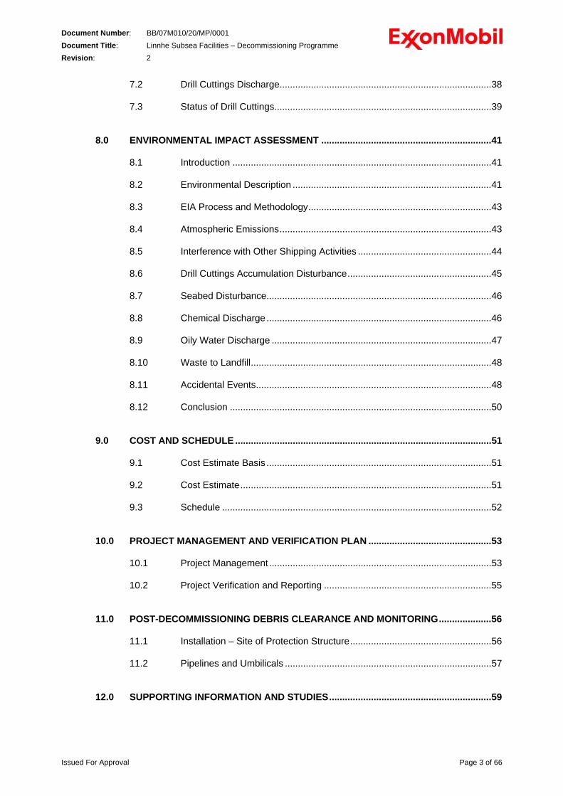
The Linnhe Field is a subsea satellite of Beryl Bravo platform, and lies approximately 4 miles north east of the platform, in Block 9/13c, and approximately 220 miles from the Scottish mainland; refer to Figures 1 and 2 below. The field was discovered in 1988, with the wildcat well 9/13c-40, and developed as a single production well, 9/13c-40z, and a single water injection well, 9/13-44z, tied back to Beryl Bravo. The field came on-stream in October 1989 and production ceased in December 1991. The cumulative production from the field was 770,000 bbls (122,422 m³) of oil and 3,460 million scf (97.976 million m³) of gas. In 1992 work was carried out in preparation for the decommissioning of Linnhe Field; both wells were plugged, abandoned and the wellheads removed; the pipelines and hydraulic / chemical umbilical were flushed and left filled with inhibited seawater. No further work on decommissioning Linnhe Field was carried out at that time as it was considered possible to re-use the facilities. This is consistent with the waste hierarchy which has re-use being preferable to recycling and disposal. However, no re-use opportunities have been identified, the facilities are of outdated design, are not now considered suitable for re-use and are therefore being decommissioned. The Decommissioning Programme has been compiled by MNS, on behalf of the Linnhe Field Partners, and is put forward for Approval in accordance with the requirements of the Petroleum Act 1998, Section 29. This document contains separate Decommissioning Programmes for each of the two sets of Notices served under Section 29 of the Petroleum Act 1998 for the Linnhe Facilities. Programme 1 covers the following Installation; • Linnhe Protection Structure Programme 2 covers the following Pipelines, all of which extend from Linnhe to Beryl Bravo; • PL659; 6” NB Production • PL660; 6” NB Production • PL662; 6” NB Gas Lift • PL661; 6” NB Water Injection • PL663 to PL668; combined hydraulic / CI umbilical In addition Programme 2 covers the electrical umbilical, which extends from Linnhe to Beryl Bravo. Section 1.2 below describes the contents of this document pertaining to the two Programmes.
Issued For Approval Page 5 of 66
Document Number: BB/07M010/20/MP/0001 Document Title: Linnhe Subsea Facilities – Decommissioning Programme Revision: 2
Scotland
Orkney Islands
Shetland Islands
Norway
UK
0 25 50 Km
MAP-NNS-LI-IM-0030
Bruce
Glassel
Leadon
NevisSouth
NessSouth
Nevis North
NevisFar North
Beryl B
BerylA
Beryl NE
LeadonNorth
Cry Noch
Nevis CentralNess
Frigg
KeithLinnhe
Legend
Active AcreageXOM InterestXOM OperatedUndev. Cond.CondensateUndev. GasGasUndev. OilOil
0 2 4 Km
MAP-NNS-LI-IM-0031
LINNHE FIELD LOCATION
Linnhe
BWISS
SPM2 SPM3
Beryl A
Beryl B
Buckland
Skene
4” Gasto/from Leadon
(disused)
Nevis South
NessNessExtension
Nevis CentralS64
Nevis WestBeryl S66
Nevis North
Lewis
Oil FlowlineWater Injection
Bundle/PIPGas Lift/Export
Chemical Injection
NevisFar North
16” Gas
20” Oil8” Oil
16” Gasfrom Gryphon
30” Gasto St. Fergus
March 2007, UK_MIS-LI-3D-PR-0043
Beryl B
NessSouth
MON-NNS-LI-PR-
FIGURE 1 Linnhe Field Location
Issued For Approval Page 6 of 66
Document Number: BB/07M010/20/MP/0001 Document Title: Linnhe Subsea Facilities – Decommissioning Programme Revision: 2
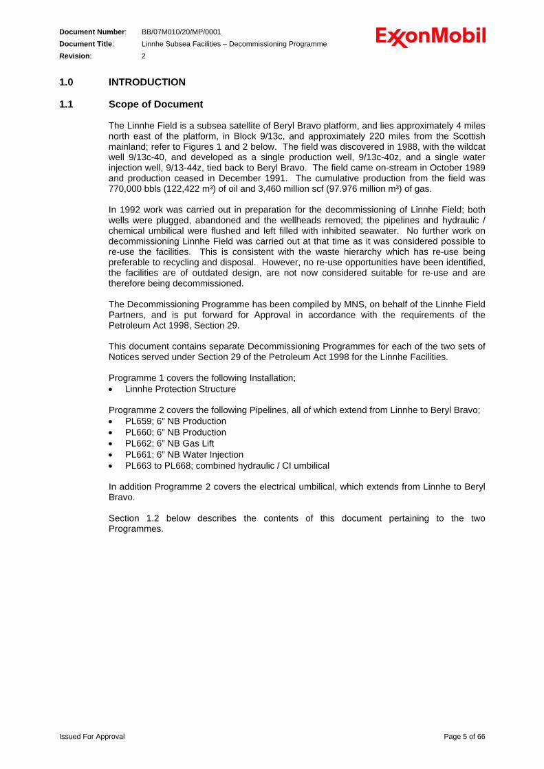
FIGURE 2 Beryl Bravo – Linnhe Field Pipeline Route [Source; Subsea 7]
Issued For Approval Page 7 of 66
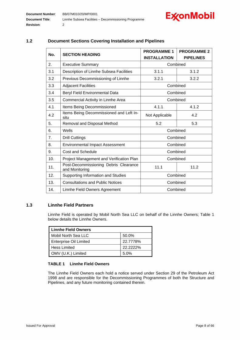
Document Number: BB/07M010/20/MP/0001 Document Title: Linnhe Subsea Facilities – Decommissioning Programme Revision: 2 1.2 Document Sections Covering Installation and Pipelines
No. SECTION HEADING PROGRAMME 1 INSTALLATION
PROGRAMME 2 PIPELINES
2. Executive Summary Combined
3.1 Description of Linnhe Subsea Facilities 3.1.1 3.1.2
3.2 Previous Decommissioning of Linnhe 3.2.1 3.2.2
3.3 Adjacent Facilities Combined
3.4 Beryl Field Environmental Data Combined
3.5 Commercial Activity in Linnhe Area Combined
4.1 Items Being Decommissioned 4.1.1 4.1.2
4.2 Items Being Decommissioned and Left In-situ Not Applicable 4.2
5. Removal and Disposal Method 5.2 5.3
6. Wells Combined
7. Drill Cuttings Combined
8. Environmental Impact Assessment Combined
9. Cost and Schedule Combined
10. Project Management and Verification Plan Combined
11. Post-Decommissioning Debris Clearance and Monitoring 11.1 11.2
12. Supporting Information and Studies Combined
13. Consultations and Public Notices Combined
14. Linnhe Field Owners Agreement Combined
1.3 Linnhe Field Partners
Linnhe Field is operated by Mobil North Sea LLC on behalf of the Linnhe Owners; Table 1 below details the Linnhe Owners.
Linnhe Field Owners Mobil North Sea LLC 50.0% Enterprise Oil Limited 22.7778% Hess Limited 22.2222% OMV (U.K.) Limited 5.0%
TABLE 1 Linnhe Field Owners The Linnhe Field Owners each hold a notice served under Section 29 of the Petroleum Act 1998 and are responsible for the Decommissioning Programmes of both the Structure and Pipelines, and any future monitoring contained therein.
Issued For Approval Page 8 of 66
Document Number: BB/07M010/20/MP/0001 Document Title: Linnhe Subsea Facilities – Decommissioning Programme Revision: 2 1.4 Abbreviations
AF Aqueous Fluid BERR Department for Business, Enterprise & Regulatory Reform BPEO Best Practicable Environmental Option CEFAS Centre for Environment, Fisheries & Aquaculture Science CI Chemical Injection CITES Convention on International Trade in Endangered Species DSV Dive Support Vessel DTI Department of Trade and Industry (now BERR) DEFRA Department for Environment, Food and Rural Affairs ED50 European Datum 1950 EIA Environmental Impact Assessment ERRV Emergency Rescue and Recovery Vessels ES Environmental Statement GA General Arrangement HP High Pressure HSE Health and Safety Executive ICES International Council for the Exploration of the Sea IMO International Maritime Organisation IPC Internal Pile Cutter KP Kilometre Point LAT Lowest Astronomical Tide MCA Maritime and Coastguard Agency MNS Mobil North Sea LLC MOM Marine Operations Manual NAF Non-aqueous Fluid NB Nominal Bore NE North East NORM Naturally Occurring Radioactive Material NSP MNS’ North Sea Production OCR Offshore Chemical Regulations OD Outside Diameter OIMS Operations Integrity Management System OPPC Oil Pollution Prevention and Control Regulations OSCP Oil Spill Contingency Plan OSRL Oil Spill Response Limited OSPAR Oslo and Paris Convention for the Protection of the Marine Environment of the
North-East Atlantic PP Project Plan ROV Remotely Operated Vehicle SAC Special Area of Conservation SEPA Scottish Environmental Protection Agency SFF Scottish Fishermen’s Federation SHE Safety, Health and Environment SOPEPs Shipboard Oil Pollution Emergency Plans UKCS United Kingdom Continental Shelf WI Water Injection WT Wall Thickness
Issued For Approval Page 9 of 66
Document Number: BB/07M010/20/MP/0001 Document Title: Linnhe Subsea Facilities – Decommissioning Programme Revision: 2 2.0 EXECUTIVE SUMMARY 2.1 Introduction
The Linnhe Field was developed as a three (two production and one water injection) well subsea satellite of Beryl Bravo platform, within Block 9/13c of the UKCS, although only one production well was completed and commissioned. The Linnhe Field is approximately 7 km north east of the Beryl Bravo platform, approximately 220 miles from the Scottish mainland, and lies in water depth of 122m. Production from Linnhe commenced in October 1989 and ceased in December 1991. The Linnhe Field facilities consist of; - piled steel wellhead Protection Structure, - four 6” diameter steel pipelines, with flexible jumpers near the Linnhe Structure - one combined hydraulic and chemical injection umbilical, - one electrical umbilical. The Protection Structure is around 225 tonne mass and 34m x 20m x 9m high. The pipelines and umbilicals lie in two trenches, on average 0.8m deep and 5.0m wide [Ref 19], except in close proximity to the Linnhe Protection Structure and Beryl Bravo. The Field facilities have been modified since cessation of production; risers re-used on Beryl Bravo and wells plugged and abandoned. No other work was carried out on decommissioning the facilities while the potential for re-use of the facilities was investigated. No alternative use for the facilities has been identified and the Field shall therefore be decommissioned. The Decommissioning Programme does not cover the pipelines and umbilicals near Beryl Bravo; these shall be decommissioned with the Beryl Bravo Platform. It is envisaged, subject to the Decommissioning Programme for Beryl Bravo, that the pipelines and umbilicals outside the trenches at Beryl Bravo shall be removed in a similar manner to the work being carried out at Linnhe.
2.2 Background to the Decommissioning Programme The Linnhe wells were plugged and abandoned in 1992 and the wellheads were removed. As part of this work the pipelines were flushed to remove hydrocarbons and the hydraulic and chemical injection lines were flushed to remove fluids. All of these lines were left filled with treated seawater. Also, to facilitate development of other subsea fields in the Beryl area, three Linnhe pipelines were disconnected at Beryl Bravo and the risers re-used. A study was completed in 1998 to evaluate the options for decommissioning of the Linnhe Field and to determine the BPEO for the Decommissioning [Ref 10]. This study included assessment of several options. The assessment reviewed the safety considerations, technical complexity and feasibility, impacts on others (e.g. users of the sea) and the estimated cost of each option. The BPEO study concluded that the recommended option was to; - remove the Protection Structure, severing the piles below seabed level, - remove the flexible jumpers, - leave the drill cuttings in situ.
Issued For Approval Page 10 of 66
Document Number: BB/07M010/20/MP/0001 Document Title: Linnhe Subsea Facilities – Decommissioning Programme Revision: 2
The BPEO Study Report was reviewed by MNS during the preparation of this Decommissioning Programme and in light of both the changes to legislation / regulatory requirements and the improvements in subsea construction methods since 1998. This review concluded that the BPEO remained valid although the removal of the flexible jumpers should be extended to include the sections of pipelines and associated protection / stabilisation materials outside the trenches, and include the umbilicals and associated protection / stabilisation materials outside the trenches.
2.3 Decommissioning Programme Proposals 2.3.1 Installation
The Protection Structure shall be removed in its entirety with the piles being severed at no less than 0.6m below seabed level and the upper sections removed. The Protection Structure shall be cut into sections before removal. The piles shall be cut, preferably using high pressure water / abrasive cutting tools deployed inside the piles, or using hydraulic / diamond wire saw. The use of explosive cutting of the piles has not been considered for the structure removal as alternative methods are available. During the cutting and removal work, some disturbance of the seabed and drill cuttings pile, see sections 2.3.4 and 7.0 below, is unavoidable, but this shall be limited to the disturbance by the divers and/or ROV carrying out the removal work and is not expected to have any long-term effect.
The Protection Structure and piles are made from structural steel, plus sacrificial Al-Zn anodes, hence shall be recycled at an onshore facility. There is expected to be limited disposal to land-fill, mainly of the marine life that has colonised the Protection Structure surfaces. The marine life present on the structure shall be surveyed during the preparation for the removal work and should Lophelia pertusa (cold water coral) be present it would be unavoidable that it was moved or displaced. Therefore in that case, an application for a permit will be made to DEFRA, as required by CITES.
2.3.2 Wells
No work is proposed on the wells as these were plugged and abandoned in 1992, and this work included removal of the wellheads and severance of the casing approximately 6m (20ft) below seabed level.
2.3.3 Pipelines The four pipelines and two umbilicals are contained within two trenches, approximately 50m apart and which extend from approximately 100m North of Beryl Bravo to approximately 30m South of Linnhe Protection Structure. The trenches range from 0.5m to 1.4m (average 0.8m) deep, and 4.5m to 6.0m (average 5.0m) wide [Ref 19]. The pipelines and trenches have been stable since installation. At Linnhe, the pipelines and umbilicals cross over and the crossings are built from concrete protection mattresses and sand/grout bags. In addition, sand / grout bags have been laid over the umbilicals to provide stabilisation and protection. The pipelines and umbilicals shall be cut within the trenches near the end at Linnhe and protection caps fitted to the cut ends, and the ends buried by relocating seabed from the adjacent area. The sections of pipelines and umbilicals up to the Protection Structure shall be removed. The various protection / stabilisation materials shall be recovered. The pipelines include isolation valves and protection structures that shall be removed with the pipelines.
Issued For Approval Page 11 of 66

Document Number: BB/07M010/20/MP/0001 Document Title: Linnhe Subsea Facilities – Decommissioning Programme Revision: 2
During the cutting and removal work, some disturbance of the seabed and accumulated drill cuttings is unavoidable, but this shall be limited to the disturbance by the divers and/or ROV carrying out the removal work and is not expected to have any long-term effect. The pipelines, and flexible jumpers are primarily fabricated from structural steel and are expected to be recycled. Similarly the pipeline isolation valves and protection structures are expected to be recycled. It is envisaged that the electrical umbilical can be stripped of the copper cores and these recycled. It is envisaged that recycling the hydraulic / CI umbilical (made of plastic hoses and steel armour wire), the plastic covers removed from the electrical umbilical and the recovered concrete mattresses and sand/grout bags will not be possible; hence these materials shall be disposed in landfill.
2.3.4 Drill Cuttings A survey was carried out in 1997 of the seabed around Linnhe, including samples taken for analysis. This survey found that there was no visible accumulation of drill cuttings, i.e. there is no cuttings ‘pile’, at Linnhe, but that the drill cuttings were well dispersed over the area around the Protection Structure, mostly to the North East. Also, this survey found that the level and persistence of the hydrocarbon contamination, which was between 18.522µg.g-1 in surface sediment (top 2cm) and 38.974µg.g-1 on underlying sediment, while being elevated, was below the OSPAR 2006/05 threshold level, 50µg.g-1, for taking action [Ref 10]. As the dispersal of the cuttings is over a large area and the level of contamination is below the threshold level, no work is being carried out to remove or contain the drill cuttings. However, further seabed samples shall be taken for analysis to ensure the contamination from drill cuttings is similar, or has degraded since the last survey.
2.3.5 Debris Removal The Decommissioning Programme includes a survey of the area around the Linnhe Field and Pipelines; the survey extends to 500m from the site of the Protection Structure and 100m either side of the pipelines. All debris found during this survey shall be removed, if it is safe to do so. Also, a trawl sweep of the site of the Protection Structure shall be undertaken as soon as possible after, and within 3 months of, the completion of the removal / recovery works to confirm the work will not affect other sea users in the future.
Issued For Approval Page 12 of 66
Document Number: BB/07M010/20/MP/0001 Document Title: Linnhe Subsea Facilities – Decommissioning Programme Revision: 2 2.3.6 Monitoring Programme
It is planned [Ref 20] to carry out a survey of the remaining sections of the pipelines and umbilicals between the Linnhe Field site and Beryl Bravo Platform in 2010, see section 11.2.2 below. This survey shall include the full length of trenches including the areas affected by the removal / recovery works, including the site of the Protection Structure and the severed piles, and shall confirm the status and condition of these areas. The seabed in the Linnhe area is firm and previous surveys have not found any seabed movement, or scouring and the pipeline trenches remain well defined with some natural back-fill. Therefore, it is expected that the 2010 survey will find the status of the pipelines, the trenches, including the buried pipeline ends, and the area around the severed piles to be similar to the as-left condition following the removal work and to previous surveys, demonstrating the stability of the seabed in the area, The scope and results of the 2010 and any future surveys shall be evaluated and this shall, in consultation with BERR and other interested parties, determine the necessity for future surveys based on change / deterioration since the last survey and evidence of impact on and by other users of the area. Samples of the seabed shall be taken from around Linnhe during the decommissioning work, (as detailed in section 11.1.1 below), and these shall be analysed for residue from drill cuttings. Should the analysis of these seabed samples find that degradation of the drill cuttings has not occurred since the last analysis then, in consultation and agreement with BERR, further surveying and/or sampling of the seabed may be carried out an appropriate time. The Linnhe Field Owners, see section 1.3 above, holding Notices served under Section 29 of the Petroleum Act 1998, are responsible for the Decommissioning Programmes, and any future monitoring contained therein, for both the Structure and Pipelines.
Issued For Approval Page 13 of 66
Document Number: BB/07M010/20/MP/0001 Document Title: Linnhe Subsea Facilities – Decommissioning Programme Revision: 2 3.0 BACKGROUND INFORMATION
3.1 Description of Linnhe Subsea Facilities
The following paragraphs describe the original as-installed Linnhe Field Subsea facilities. Some work in preparation for decommissioning has been carried out, in 1992, and the current status is described in subsection 3.2 below. Linnhe Field lies approximately 7 km north east of the Beryl Bravo Platform in Block 9/13c of the UKCS. The field was developed in 1989 as a subsea tie-back to the Beryl Bravo Platform and consisted of one subsea production well (9/13c-40z) and one subsea water injection well (9/13c-44). The development included scope for a further well that was not drilled. Refer to Figure 1 and Figure 2, which are both presented in Section 1 above.
3.1.1 Installation
The wells were protected by a piled steel Protection Structure / manifold, which is approximately 35m long x 20m wide x 9m high. The Protection Structure is constructed of tubular steel and is an open frame with sloping sides. There are three compartments to the structure; one for each planned well and each compartment has been fitted with two hinged roof panels. The structure is piled through the four corner ‘legs’ and the piles were swaged to the legs. The structure is protected from corrosion by sacrificial anodes.
3.1.2 Pipelines
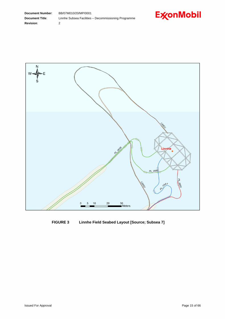
Four pipelines; two 6” NB Production (PL659 and PL660), one 6” NB Gas Lift (PL662) and one 6” NB Water Injection (PL661), an electrical umbilical and a combined hydraulic / CI umbilical (PL663 to PL668) are installed between Beryl Bravo and the Protection Structure. The pipelines and umbilicals are laid approximately NE from Beryl Bravo and cross over the two 32” Frigg Gas Pipelines. The 32” Vesterled / Heimdal Gas Export Pipeline crosses over the Linnhe Pipelines. The pipelines and umbilicals are laid in two trenches, of average 0.8m depth; one trench for PL659 and PL660, the other for PL661, PL662, the electrical umbilical and the hydraulic / CI umbilical from Beryl Bravo. The trenches extend from approximately 100m north of Beryl Bravo to approximately 30m south of the Protection Structure. Refer to Figure 2 above for the pipeline route and relative location of Beryl Bravo and Linnhe Field. At the Linnhe Field, the pipelines terminate in two Valve Protection Structures, which contain a single isolation valve for each pipeline, and flexible jumpers connect between the valve and the piping within the Protection Structure. Concrete protection mattresses have been laid intermittently over the flexible jumpers for stabilisation and crossing protection. The umbilicals are laid in a loop between the trench and Protection Structure and sand/ grout bags were laid on top for stabilisation. Refer to Figure 3 below for the layout at Linnhe. At Beryl Bravo, the Production and Gas Lift Pipelines have been disconnected from Beryl Bravo at the seabed and the risers have been re-used, the Water Injection Pipeline is routed through Caisson B3, Riser 1 on the north face of the jacket. The Hydraulic / CI Umbilical is routed through Caisson B3, Riser 4, and the electrical umbilical is routed through J-Tube 27.
Issued For Approval Page 14 of 66
Document Number: BB/07M010/20/MP/0001 Document Title: Linnhe Subsea Facilities – Decommissioning Programme Revision: 2
FIGURE 3 Linnhe Field Seabed Layout [Source; Subsea 7]
Issued For Approval Page 15 of 66
Document Number: BB/07M010/20/MP/0001 Document Title: Linnhe Subsea Facilities – Decommissioning Programme Revision: 2 3.2 Preparation for Decommissioning of Linnhe
Linnhe Field started production in October 1989 and production ceased in December 1991. After production ceased, the Cessation of Production Plan [Ref 1] was approved in April 1992. The Cessation of Production Document included the plans to immediately carry out work in preparation to decommission the field, and these were further detailed in the Abandonment Document [Ref 2]. However, although the Abandonment Document, which constituted the Decommissioning Programme at that time, was presented to BERR (then DTI) it was not formally approved. The preparatory work, which was completed in 1992 [Refs 3, 4, 5 and 6], comprised the following works; a) Plug and abandon the two wells. b) Flush the pipelines and umbilicals and leave filled with inhibited seawater; see section
3.2.2. c) Disconnect the pipelines, and umbilicals, from the wellheads. d) Remove the two wellheads. Further work was carried out to allow re-use of three Linnhe Pipeline Risers at Beryl Bravo. This work comprised disconnection of the two production and one gas lift pipelines from the Riser Caisson at Beryl Bravo. The WI pipeline remains connected to Beryl Bravo.
3.2.1 Preparation for Decommissioning - Installation
The preparation for decommissioning work was limited to plug, abandon and removal of the wellheads. No other work was carried out on the Installation.
3.2.2 Preparation for Decommissioning - Pipelines and Umbilicals
The wellhead removal works involved flushing the pipelines and hydraulic / chemical umbilical. The Production Pipeline PL659 was flushed with treated seawater in a round trip to Beryl Bravo through the Gas Lift Pipeline, PL662, across well 9/13-40z. The work involved a series of flushes to achieve a cleanliness of <2000ppm oil in water, with the final seawater injection being treated with 600ppm TROS 650 (O2 scavenger, biocide and corrosion inhibitor mixture). Production pipeline PL660 was not tied in at the Linnhe Protection Structure and has never been used, therefore it has remained filled with treated seawater following the hydro-testing carried out during installation. The Water Injection Pipeline was not worked on during the wellhead removal and was left filled with injection seawater. Subsequent work at Beryl Bravo disconnected the Production and Gas Lift Pipelines to allow the respective risers to be re-used. During the wellhead removal works the hydraulic / chemical umbilical was fitted with loops at the termination and similar flushing carried out from Beryl Bravo. The electrical umbilical was fitted with shorting plugs at the termination
3.3 Adjacent Facilities
The Linnhe Field is approximately 7 km North of Beryl Bravo and there are no other fields, subsea facilities or cables in the vicinity of the Linnhe Field or between Linnhe and Beryl Bravo, refer to Figures 1 and 2, presented in Section 1 above.
Issued For Approval Page 16 of 66
Document Number: BB/07M010/20/MP/0001 Document Title: Linnhe Subsea Facilities – Decommissioning Programme Revision: 2
The Linnhe pipelines cross the two, trenched, 32” Gas Pipelines (PL6N and PL7N) from the decommissioned, Frigg Field. The crossing is at approximately KP 4.5; KP0 being at Beryl Bravo. The crossing consists of bitumen-filled protection mattresses laid over the Frigg Pipelines and rock dump over the Linnhe Pipelines between the trenches either side of the Frigg Crossing. The 32” Vesterled Gas Export Pipeline (PL1839) from Heimdal Field, in Norway, was laid over the trenched Linnhe Pipelines at approximately KP 5.4 in 2002 and rock-dump was placed over the crossing. The three gas pipelines’ crossings noted above will be unaffected by the planned decommissioning works described herein. No firm plans are in place for decommissioning the Frigg and Vesterled Pipelines at this time. However, when those decommissioning plans are finalised, the Decommissioning of the Linnhe Pipelines shall be reviewed if the plans for decommissioning of the Frigg and Vesterled pipelines will change the condition of the Linnhe pipelines.
3.4 Beryl Field Environmental Data
The environmental data for Beryl Field is considered as representative for the Beryl Area, including Linnhe Field, and where no specific data is available for Linnhe Field then the Beryl Field data is given below.
3.4.1 Water Depth
• Beryl Bravo : 119 m LAT • Linnhe Field : 122 m LAT
3.4.2 Tidal Ranges
• Mean high water spring (MHWS): 1.1m • Highest astronomical tide (HAT): 1.1m • Extreme surge level (100 year): 1.1m • Extreme still water level above LAT (100 year): 2.2m
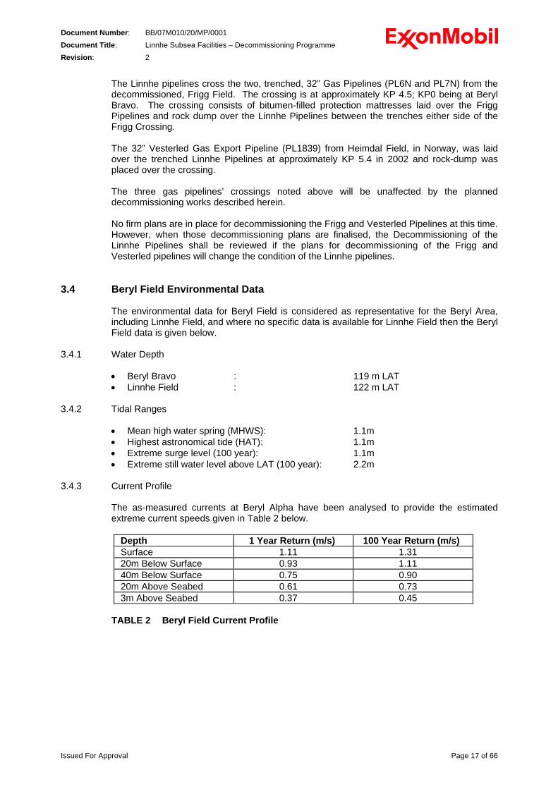
3.4.3 Current Profile
The as-measured currents at Beryl Alpha have been analysed to provide the estimated extreme current speeds given in Table 2 below.
Depth 1 Year Return (m/s) 100 Year Return (m/s) Surface 1.11 1.31 20m Below Surface 0.93 1.11 40m Below Surface 0.75 0.90 20m Above Seabed 0.61 0.73 3m Above Seabed 0.37 0.45
TABLE 2 Beryl Field Current Profile
Issued For Approval Page 17 of 66
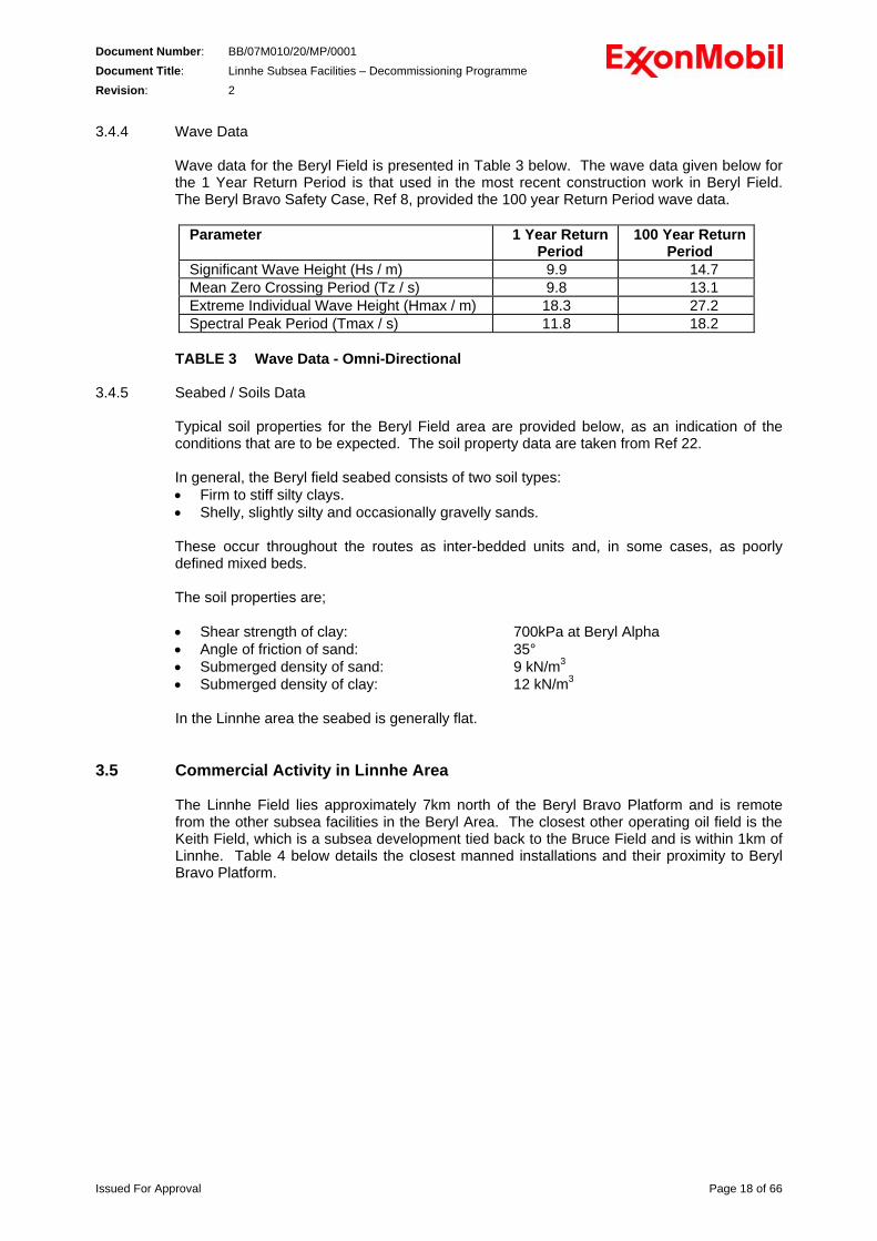
Document Number: BB/07M010/20/MP/0001 Document Title: Linnhe Subsea Facilities – Decommissioning Programme Revision: 2 3.4.4 Wave Data
Wave data for the Beryl Field is presented in Table 3 below. The wave data given below for the 1 Year Return Period is that used in the most recent construction work in Beryl Field. The Beryl Bravo Safety Case, Ref 8, provided the 100 year Return Period wave data.
Parameter 1 Year Return
Period 100 Year Return
Period Significant Wave Height (Hs / m) 9.9 14.7 Mean Zero Crossing Period (Tz / s) 9.8 13.1 Extreme Individual Wave Height (Hmax / m) 18.3 27.2 Spectral Peak Period (Tmax / s) 11.8 18.2
TABLE 3 Wave Data - Omni-Directional
3.4.5 Seabed / Soils Data
Typical soil properties for the Beryl Field area are provided below, as an indication of the conditions that are to be expected. The soil property data are taken from Ref 22. In general, the Beryl field seabed consists of two soil types: • Firm to stiff silty clays. • Shelly, slightly silty and occasionally gravelly sands.
These occur throughout the routes as inter-bedded units and, in some cases, as poorly defined mixed beds. The soil properties are; • Shear strength of clay: 700kPa at Beryl Alpha • Angle of friction of sand: 35° • Submerged density of sand: 9 kN/m3 • Submerged density of clay: 12 kN/m3 In the Linnhe area the seabed is generally flat.
3.5 Commercial Activity in Linnhe Area
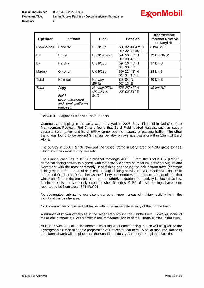
The Linnhe Field lies approximately 7km north of the Beryl Bravo Platform and is remote from the other subsea facilities in the Beryl Area. The closest other operating oil field is the Keith Field, which is a subsea development tied back to the Bruce Field and is within 1km of Linnhe. Table 4 below details the closest manned installations and their proximity to Beryl Bravo Platform.
Issued For Approval Page 18 of 66
DocuDocuRev
Issued For App
ment Number: BB/07M010/20/MP/0001 ment Title: Linnhe Subsea Facilities – Decommissioning Programme
ision: 2
roval Page 19 of 66
Operator
Platform
Block
Position Approximate
Position Relative to Beryl ‘B’
ExxonMobil Beryl ‘A’ UK 9/13a 59° 32’ 44.47" N 01° 32’ 16.45" E
8 km SSE
BP Bruce UK 9/8a-9/9b 59° 50’ 00" N 01° 30’ 40" E
12 km NNW
BP Harding UK 9/23b 59° 16’ 46" N 01° 30’ 38" E
37 km S
Maersk Gryphon UK 9/18b 59º 21’ 42" N 01º 34’ 18" E
28 km S
Total Heimdal Norway 25/4a
59° 34’ N 02° 13’ E
40 km E
Total Frigg Field decommissioned and steel platforms removed.
Norway 25/1a UK 10/1 & 9/10
59° 25’ 47" N 02° 03’ 51" E
45 km NE
TABLE 4 Adjacent Manned Installations Commercial shipping in the area was surveyed in 2006 Beryl Field ‘Ship Collision Risk Management Review’, [Ref 9], and found that Beryl Field related vessels, such as supply vessels, Beryl tanker and Beryl ERRV comprised the majority of passing traffic. The other traffic was found to be around 3 transits per day on average passing within 15nm of Beryl Alpha. The survey in 2006 [Ref 9] reviewed the vessel traffic in Beryl area of >300 gross tonnes, which excludes most fishing vessels. The Linnhe area lies in ICES statistical rectangle 48F1. From the Xodus EIA [Ref 21], demersal fishing activity is highest, with the activity classed as medium, between August and November with the most commonly used fishing gear being the pair bottom trawl (common fishing method for demersal species). Pelagic fishing activity in ICES block 48F1 occurs in the period October to December as the fishery concentrates on the mackerel population that winter and feed in the area on their return southerly migration, and activity is classed as low. Linnhe area is not commonly used for shell fisheries; 0.1% of total landings have been reported to be from area 48F1 [Ref 21]. No designated submarine exercise grounds or known areas of military activity lie in the vicinity of the Linnhe area. No known active or disused cables lie within the immediate vicinity of the Linnhe Field. A number of known wrecks lie in the wider area around the Linnhe Field. However, none of these obstructions are located within the immediate vicinity of the Linnhe subsea installation. At least 6 weeks prior to the decommissioning work commencing, notice will be given to the Hydrographic Office to enable preparation of Notices to Mariners. Also, at that time, notice of the planned work will be placed on the Sea Fish Industry Authority’s Kingfisher Bulletin.
Document Number: BB/07M010/20/MP/0001 Document Title: Linnhe Subsea Facilities – Decommissioning Programme Revision: 2
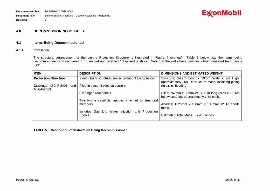
4.0 DECOMMISSIONING DETAILS 4.1 Items Being Decommissioned 4.1.1 Installation
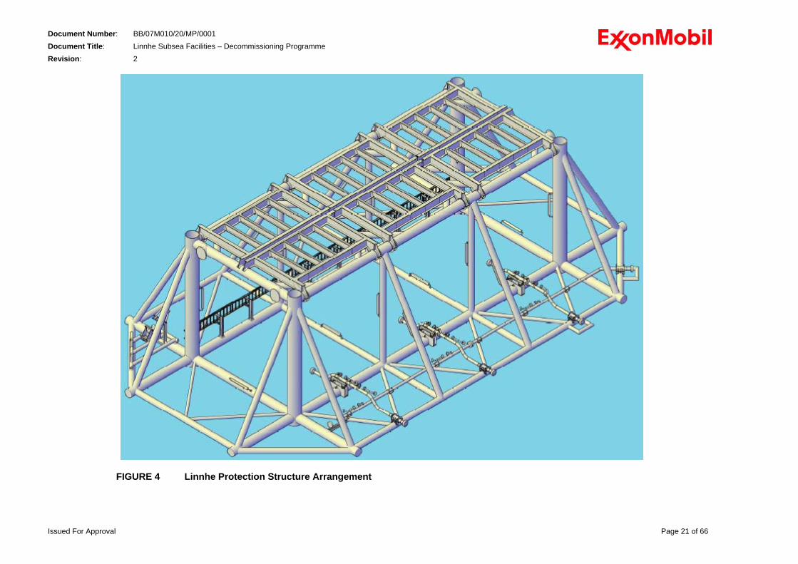
The structural arrangement of the Linnhe Protection Structure is illustrated in Figure 4 overleaf. Table 5 below lists the items being decommissioned and recovered from seabed and recycled / disposed onshore. Note that the wells have previously been removed from Linnhe Field. ITEM DESCRIPTION DIMENSIONS AND ESTIMATED WEIGHT Protection Structure Drawings M-X-F-2401 and M-X-F-2403
Steel tubular structure; see schematic drawing below. Piled in place; 4 piles, at corners. Six hinged roof panels. Twenty-one sacrificial anodes attached to structural members. Includes Gas Lift, Water Injection and Production Spools.
Structure; 34.2m Long x 19.6m Wide x 9m High; approximately 200 Te structure mass, including piping (in air, nil flooding). Piles; 762mm x 38mm WT x 12m long (piles cut 0.6m below seabed); approximately 7 Te each. Anodes; 1525mm x 130mm x 135mm; <2 Te anode mass. Estimated Total Mass 228 Tonnes
TABLE 5 Description of Installation Being Decommissioned
Issued For Approval Page 20 of 66
Document Number: BB/07M010/20/MP/0001 Document Title: Linnhe Subsea Facilities – Decommissioning Programme Revision: 2
FIGURE 4 Linnhe Protection Structure Arrangement
Issued For Approval Page 21 of 66
Document Number: BB/07M010/20/MP/0001 Document Title: Linnhe Subsea Facilities – Decommissioning Programme Revision: 2
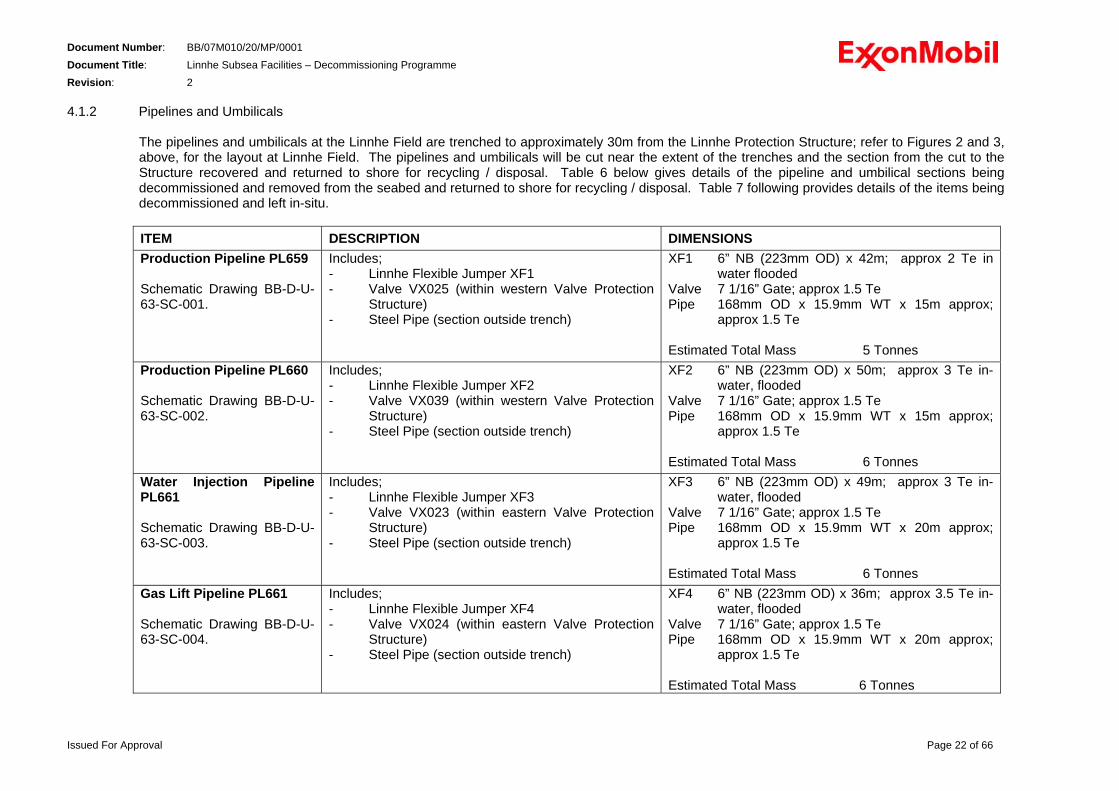
4.1.2 Pipelines and Umbilicals
The pipelines and umbilicals at the Linnhe Field are trenched to approximately 30m from the Linnhe Protection Structure; refer to Figures 2 and 3, above, for the layout at Linnhe Field. The pipelines and umbilicals will be cut near the extent of the trenches and the section from the cut to the Structure recovered and returned to shore for recycling / disposal. Table 6 below gives details of the pipeline and umbilical sections being decommissioned and removed from the seabed and returned to shore for recycling / disposal. Table 7 following provides details of the items being decommissioned and left in-situ.
ITEM DESCRIPTION DIMENSIONSProduction Pipeline PL659 Schematic Drawing BB-D-U-63-SC-001.
Includes; - Linnhe Flexible Jumper XF1 - Valve VX025 (within western Valve Protection
Structure) - Steel Pipe (section outside trench)
XF1 6” NB (223mm OD) x 42m; approx 2 Te in water flooded
Valve 7 1/16” Gate; approx 1.5 Te Pipe 168mm OD x 15.9mm WT x 15m approx;
approx 1.5 Te Estimated Total Mass 5 Tonnes
Production Pipeline PL660 Schematic Drawing BB-D-U-63-SC-002.
Includes; - Linnhe Flexible Jumper XF2 - Valve VX039 (within western Valve Protection
Structure) - Steel Pipe (section outside trench)
XF2 6” NB (223mm OD) x 50m; approx 3 Te in-water, flooded
Valve 7 1/16” Gate; approx 1.5 Te Pipe 168mm OD x 15.9mm WT x 15m approx;
approx 1.5 Te Estimated Total Mass 6 Tonnes
Water Injection Pipeline PL661 Schematic Drawing BB-D-U-63-SC-003.
Includes; - Linnhe Flexible Jumper XF3 - Valve VX023 (within eastern Valve Protection
Structure) - Steel Pipe (section outside trench)
XF3 6” NB (223mm OD) x 49m; approx 3 Te in-water, flooded
Valve 7 1/16” Gate; approx 1.5 Te Pipe 168mm OD x 15.9mm WT x 20m approx;
approx 1.5 Te Estimated Total Mass 6 Tonnes
Gas Lift Pipeline PL661 Schematic Drawing BB-D-U-63-SC-004.
Includes; - Linnhe Flexible Jumper XF4 - Valve VX024 (within eastern Valve Protection
Structure) - Steel Pipe (section outside trench)
XF4 6” NB (223mm OD) x 36m; approx 3.5 Te in-water, flooded
Valve 7 1/16” Gate; approx 1.5 Te Pipe 168mm OD x 15.9mm WT x 20m approx;
approx 1.5 Te Estimated Total Mass 6 Tonnes
Issued For Approval Page 22 of 66
Document Number: BB/07M010/20/MP/0001 Document Title: Linnhe Subsea Facilities – Decommissioning Programme Revision: 2
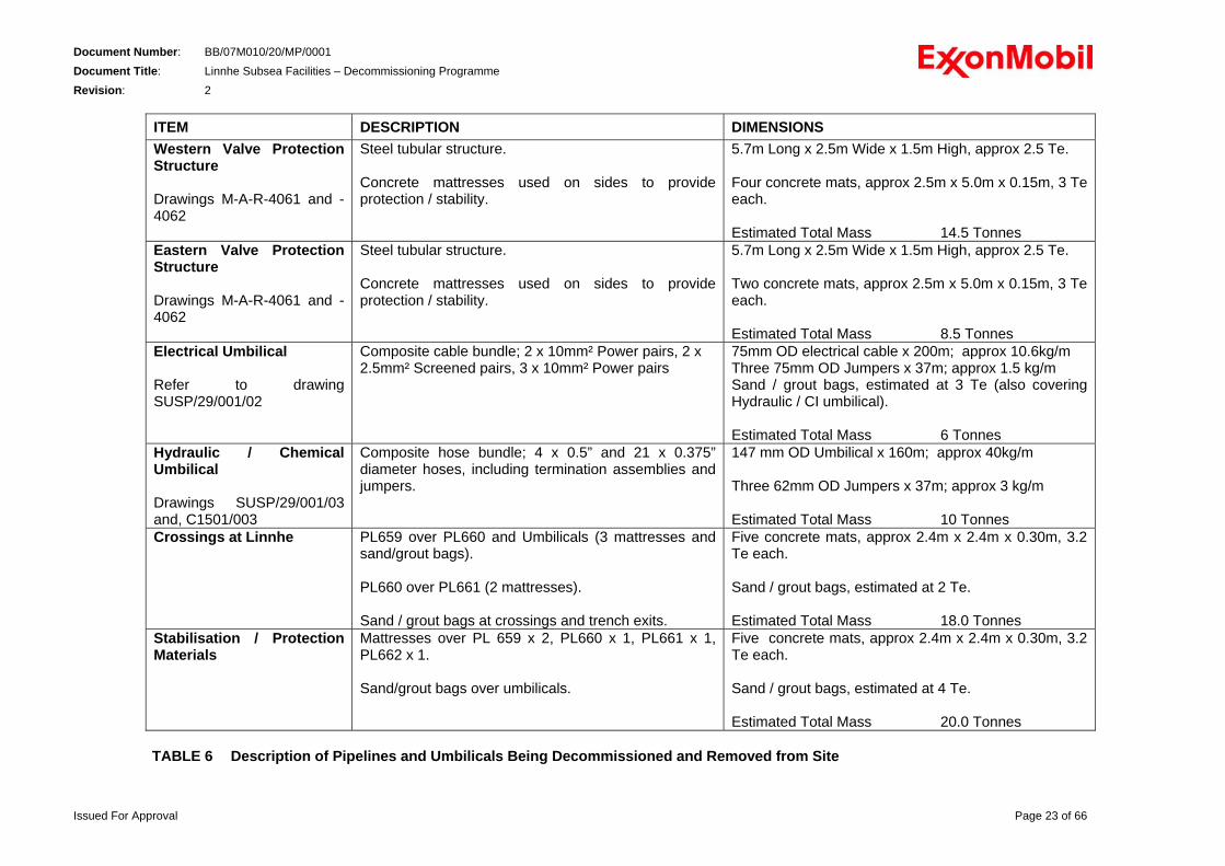
ITEM DESCRIPTION DIMENSIONS Western Valve Protection Structure Drawings M-A-R-4061 and -4062
Steel tubular structure. Concrete mattresses used on sides to provide protection / stability.
5.7m Long x 2.5m Wide x 1.5m High, approx 2.5 Te. Four concrete mats, approx 2.5m x 5.0m x 0.15m, 3 Te each. Estimated Total Mass 14.5 Tonnes
Eastern Valve Protection Structure Drawings M-A-R-4061 and -4062
Steel tubular structure. Concrete mattresses used on sides to provide protection / stability.
5.7m Long x 2.5m Wide x 1.5m High, approx 2.5 Te. Two concrete mats, approx 2.5m x 5.0m x 0.15m, 3 Te each. Estimated Total Mass 8.5 Tonnes
Electrical Umbilical Refer to drawinSUSP/29/001/02
g
Composite cable bundle; 2 x 10mm² Power pairs, 2 x 2.5mm² Screened pairs, 3 x 10mm² Power pairs
75mm OD electrical cable x 200m; approx 10.6kg/m Three 75mm OD Jumpers x 37m; approx 1.5 kg/m Sand / grout bags, estimated at 3 Te (also covering Hydraulic / CI umbilical). Estimated Total Mass 6 Tonnes
Hydraulic / Chemical Umbilical Drawings SUSP/29/001/03 and, C1501/003
Composite hose bundle; 4 x 0.5” and 21 x 0.375” diameter hoses, including termination assemblies and jumpers.
147 mm OD Umbilical x 160m; approx 40kg/m Three 62mm OD Jumpers x 37m; approx 3 kg/m Estimated Total Mass 10 Tonnes
Crossings at Linnhe PL659 over PL660 and Umbilicals (3 mattresses and sand/grout bags). PL660 over PL661 (2 mattresses). Sand / grout bags at crossings and trench exits.
Five concrete mats, approx 2.4m x 2.4m x 0.30m, 3.2 Te each. Sand / grout bags, estimated at 2 Te. Estimated Total Mass 18.0 Tonnes
Stabilisation / Protection Materials
Mattresses over PL 659 x 2, PL660 x 1, PL661 x 1, PL662 x 1. Sand/grout bags over umbilicals.
Five concrete mats, approx 2.4m x 2.4m x 0.30m, 3.2 Te each. Sand / grout bags, estimated at 4 Te. Estimated Total Mass 20.0 Tonnes
TABLE 6 Description of Pipelines and Umbilicals Being Decommissioned and Removed from Site
Issued For Approval Page 23 of 66
Document Number: BB/07M010/20/MP/0001 Document Title: Linnhe Subsea Facilities – Decommissioning Programme Revision: 2
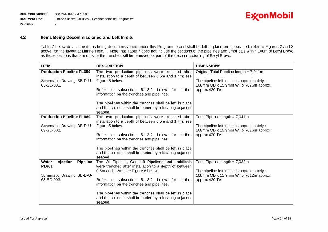
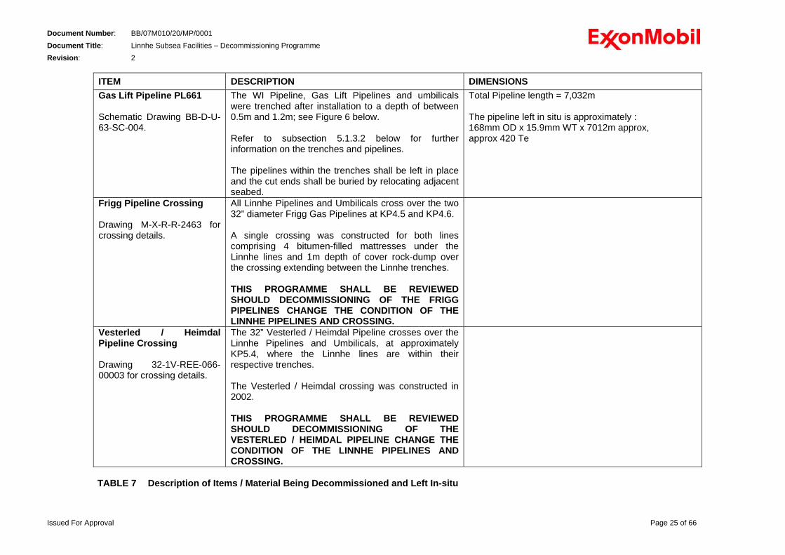
4.2 Items Being Decommissioned and Left In-situ
Table 7 below details the items being decommissioned under this Programme and shall be left in place on the seabed; refer to Figures 2 and 3, above, for the layout at Linnhe Field. . Note that Table 7 does not include the sections of the pipelines and umbilicals within 100m of Beryl Bravo, as those sections that are outside the trenches will be removed as part of the decommissioning of Beryl Bravo.
ITEM DESCRIPTION DIMENSIONSProduction Pipeline PL659 Schematic Drawing BB-D-U-63-SC-001.
The two production pipelines were trenched after installation to a depth of between 0.5m and 1.4m; see Figure 5 below. Refer to subsection 5.1.3.2 below for further information on the trenches and pipelines. The pipelines within the trenches shall be left in place and the cut ends shall be buried by relocating adjacent seabed.
Original Total Pipeline length = 7,041m The pipeline left in situ is approximately : 168mm OD x 15.9mm WT x 7026m approx, approx 420 Te
Production Pipeline PL660 Schematic Drawing BB-D-U-63-SC-002.
The two production pipelines were trenched after installation to a depth of between 0.5m and 1.4m; see Figure 5 below. Refer to subsection 5.1.3.2 below for further information on the trenches and pipelines. The pipelines within the trenches shall be left in place and the cut ends shall be buried by relocating adjacent seabed.
Total Pipeline length = 7,041m The pipeline left in situ is approximately : 168mm OD x 15.9mm WT x 7026m approx, approx 420 Te
Water Injection Pipeline PL661 Schematic Drawing BB-D-U-63-SC-003.
The WI Pipeline, Gas Lift Pipelines and umbilicals were trenched after installation to a depth of between 0.5m and 1.2m; see Figure 6 below. Refer to subsection 5.1.3.2 below for further information on the trenches and pipelines. The pipelines within the trenches shall be left in place and the cut ends shall be buried by relocating adjacent seabed.
Total Pipeline length = 7,032m The pipeline left in situ is approximately : 168mm OD x 15.9mm WT x 7012m approx, approx 420 Te
Issued For Approval Page 24 of 66
DocumenDocumenRevisio
Issued For App
t Number: BB/07M010/20/MP/0001 t Title: Linnhe Subsea Facilities – Decommissioning Programme
n: 2
roval Page 25 of 66
ITEM DESCRIPTION DIMENSIONS Gas Lift Pipeline PL661 Schematic Drawing BB-D-U-63-SC-004.
The WI Pipeline, Gas Lift Pipelines and umbilicals were trenched after installation to a depth of between 0.5m and 1.2m; see Figure 6 below. Refer to subsection 5.1.3.2 below for further information on the trenches and pipelines. The pipelines within the trenches shall be left in place and the cut ends shall be buried by relocating adjacent seabed.
Total Pipeline length = 7,032m The pipeline left in situ is approximately : 168mm OD x 15.9mm WT x 7012m approx, approx 420 Te
Frigg Pipeline Crossing Drawing M-X-R-R-2463 for crossing details.
All Linnhe Pipelines and Umbilicals cross over the two 32” diameter Frigg Gas Pipelines at KP4.5 and KP4.6. A single crossing was constructed for both lines comprising 4 bitumen-filled mattresses under the Linnhe lines and 1m depth of cover rock-dump over the crossing extending between the Linnhe trenches. THIS PROGRAMME SHALL BE REVIEWED SHOULD DECOMMISSIONING OF THE FRIGG PIPELINES CHANGE THE CONDITION OF THE LINNHE PIPELINES AND CROSSING.
Vesterled / HeimdalPipeline Crossing
The 32” Vesterled / Heimdal Pipeline crosses over the Linnhe Pipelines and Umbilicals, at approximately KP5.4, where the Linnhe lines are within their respective trenches.
Drawing 32-1V-REE-066-00003 for crossing details.
The Vesterled / Heimdal crossing was constructed in 2002. THIS PROGRAMME SHALL BE REVIEWED SHOULD DECOMMISSIONING OF THE VESTERLED / HEIMDAL PIPELINE CHANGE THE CONDITION OF THE LINNHE PIPELINES AND CROSSING.
TABLE 7 Description of Items / Material Being Decommissioned and Left In-situ
Document Number: BB/07M010/20/MP/0001 Document Title: Linnhe Subsea Facilities – Decommissioning Programme Revision: 2 5.0 REMOVAL AND DISPOSAL METHOD
5.1 Removal / Decommissioning Options
The BPEO Analysis [Ref 10] reviewed the decommissioning and removal options for Linnhe Field Decommissioning in detail and compared the options in respect of their technical practicability / complexity (including safety hazards and risks), their environmental impact and their cost. The options considered in the BPEO are described in Table 8 below. The information contained in the BPEO Analysis remains valid, except for the cost estimates.
Option I Total removal of the wellhead Protection Structure (including flexible jumpers
and drill cuttings pile: a) cut the piles by water abrasive jetting and remove the structure in a single
lift; b) cut the piles by shaped charge and remove the structure in a single lift; c) cut the piles by water abrasive jetting and cut the structure into several
sections subsea; d) cut the piles by shaped charge and cut the structure into several sections
subsea.
Option II Removal of the wellhead Protection Structure (including flexible jumpers) only and drill cuttings left in place: removal of structure by methods a) to d) as in Option I.
Option III Removal of the structure only and capping of drill cuttings: removal of structure by methods a) to d) as in Option I.
Option IV Removal of the structure and active dispersion of drill cuttings by over-trawling: removal of structure by methods a) to d) as in Option I
Option V Leave the structure and drill cuttings in-situ: a) mothball; b) for all time.
Option VI Initial use of the structure and cuttings pile for research purposes, and subsequent disposal.
TABLE 8 Decommissioning Options Considered in BPEO 1998 The MNS review of the BPEO while preparing this Programme identified that the use of explosives is now not being considered, as noted in section 2.3.1, and that the drill cuttings should be left in place and undisturbed; see section 7 below. Therefore, during the compilation of this programme three options were considered in detail; 1. Leave the Protection Structure and pipelines / umbilicals in-situ; 2. Remove all parts of the Protection Structure and pipelines / umbilicals; 3. Remove the Protection Structure in its entirety and remove the sections of pipelines /
umbilicals outside the trenches.
Issued For Approval Page 26 of 66
Document Number: BB/07M010/20/MP/0001 Document Title: Linnhe Subsea Facilities – Decommissioning Programme Revision: 2
The following subsections briefly describe the three Removal / Decommissioning Options considered further in preparing this Programme. The consideration of each Option included review of the regulatory requirements, the technical complexity of the work, the risks to personnel and environment, the environmental impact, impact to other users of the sea and cost. The consideration was largely based on the information contained in the BPEO and has been summarised herein. Section 5.1 describes the Options 1 and 2, which have both been concluded as unsuitable for the Linnhe Field Protection Structure and Pipelines. Section 5.2 below describes Option 3, the selected and preferred removal / decommissioning method for the Installation, and section 5.3 similarly describes the selected removal / decommissioning method for the pipelines and umbilicals. Please refer to section 7 below for details of the drill cuttings at Linnhe Field. Note that the Decommissioning Programme described in this document only relates to the Linnhe Field Area. The sections of pipelines and umbilicals at Beryl Bravo are not part of this Programme; these shall be included in the Decommissioning Programme for the Beryl Bravo Platform and Pipelines.
5.1.1 Leave in Place This option does not comply with the requirements of the OSPAR Decision 98/3, and is therefore not acceptable.
5.1.2 Re-Use 5.1.2.1 Re-Use of Installation – Protection Structure
The Linnhe Protection Structure has been left in-situ since the cessation of production (1992) and the potential re-use of the facilities have been reviewed by MNS and others as development in the adjacent areas progressed. No re-use of the Protection Structure has been found to date, is considered extremely unlikely and is therefore not being considered further.
5.1.2.2 Re-Use of Pipelines and Umbilicals
Three of the pipelines have been re-configured since production ceased at Linnhe; both production and the gas lift pipelines have been disconnected from the Riser Caisson at Beryl Bravo. The WI pipeline remains connected to the Beryl Bravo. Re-use of the pipelines and umbilicals is not feasible as there are no known future developments in Linnhe Area and it would not be possible to recover and redeploy the pipeline and umbilicals.
5.1.3 Removal of the Complete Facilities
5.1.3.1 Removal of Installation – Protection Structure
The Protection Structure is now of a dated design. Re-use is not considered feasible and, in accordance with the requirements of the OSPAR Decision 98/3, it shall be removed in its entirety. On completion of the removal works the 500m safety zone around Linnhe Field will no longer be required and an application shall be made to the HSE for its removal. The Protection Structure includes the piles, which are buried approximately 12m below seabed level. The preferred method is to remove the complete Protection Structure, severing the piles no less than 0.6m below seabed level; refer to section 5.2 below.
Issued For Approval Page 27 of 66
Document Number: BB/07M010/20/MP/0001 Document Title: Linnhe Subsea Facilities – Decommissioning Programme Revision: 2
Removing the complete length of the piles would involve considerable disturbance of the seabed at the Linnhe Field location and it is considered that the benefits of complete removal of the seabed piles are less than the disturbance caused by the removal. Therefore, removing the length of the piles deeper than 0.6m below seabed is not considered an acceptable option.
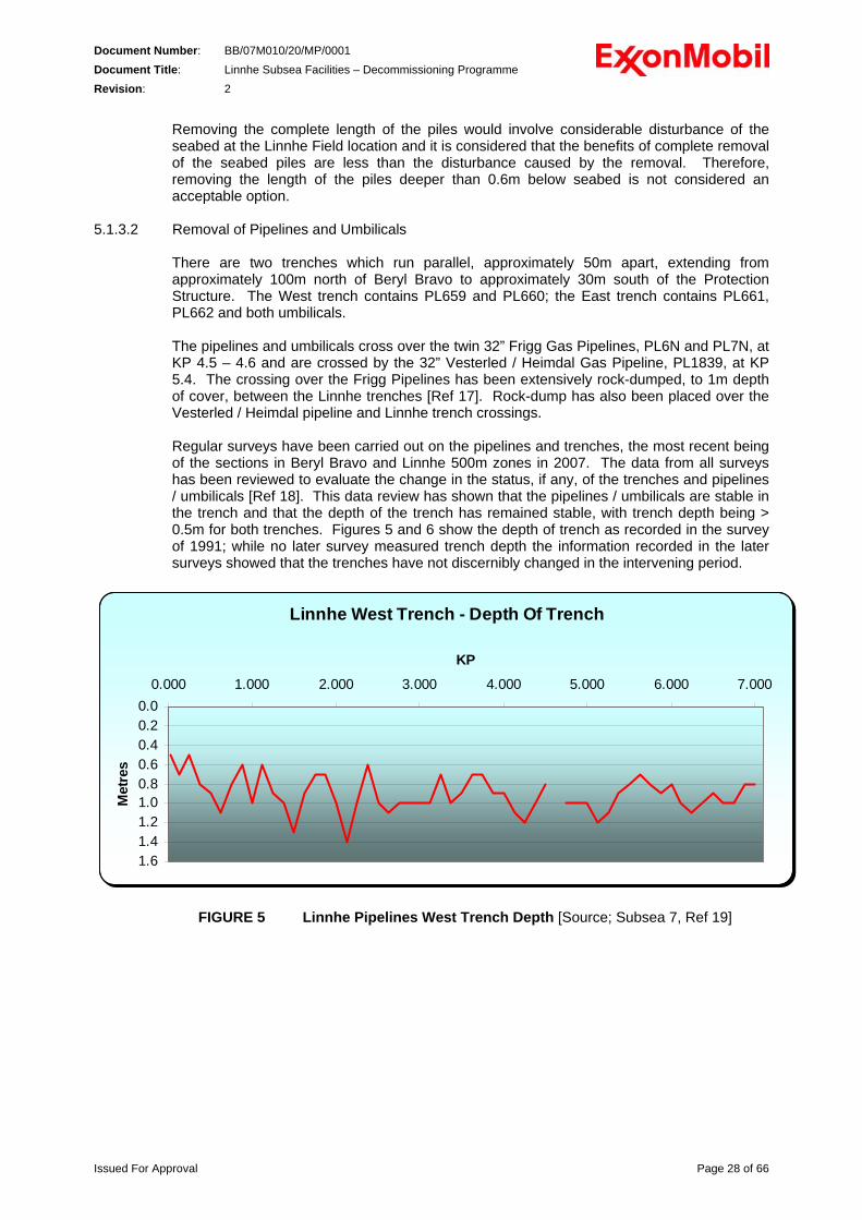
5.1.3.2 Removal of Pipelines and Umbilicals There are two trenches which run parallel, approximately 50m apart, extending from approximately 100m north of Beryl Bravo to approximately 30m south of the Protection Structure. The West trench contains PL659 and PL660; the East trench contains PL661, PL662 and both umbilicals. The pipelines and umbilicals cross over the twin 32” Frigg Gas Pipelines, PL6N and PL7N, at KP 4.5 – 4.6 and are crossed by the 32” Vesterled / Heimdal Gas Pipeline, PL1839, at KP 5.4. The crossing over the Frigg Pipelines has been extensively rock-dumped, to 1m depth of cover, between the Linnhe trenches [Ref 17]. Rock-dump has also been placed over the Vesterled / Heimdal pipeline and Linnhe trench crossings. Regular surveys have been carried out on the pipelines and trenches, the most recent being of the sections in Beryl Bravo and Linnhe 500m zones in 2007. The data from all surveys has been reviewed to evaluate the change in the status, if any, of the trenches and pipelines / umbilicals [Ref 18]. This data review has shown that the pipelines / umbilicals are stable in the trench and that the depth of the trench has remained stable, with trench depth being > 0.5m for both trenches. Figures 5 and 6 show the depth of trench as recorded in the survey of 1991; while no later survey measured trench depth the information recorded in the later surveys showed that the trenches have not discernibly changed in the intervening period.
Linnhe West Trench - Depth Of Trench
0.00.20.40.60.81.01.21.41.6
0.000 1.000 2.000 3.000 4.000 5.000 6.000 7.000
KP
Met
res
FIGURE 5 Linnhe Pipelines West Trench Depth [Source; Subsea 7, Ref 19]
Issued For Approval Page 28 of 66
Document Number: BB/07M010/20/MP/0001 Document Title: Linnhe Subsea Facilities – Decommissioning Programme Revision: 2
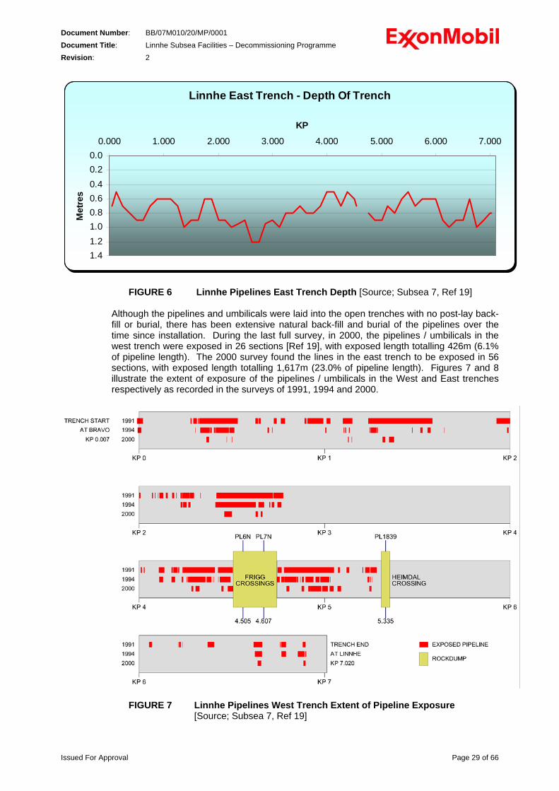
Linnhe East Trench - Depth Of Trench
0.00.20.40.60.81.01.21.4
0.000 1.000 2.000 3.000 4.000 5.000 6.000 7.000
KP
Met
res
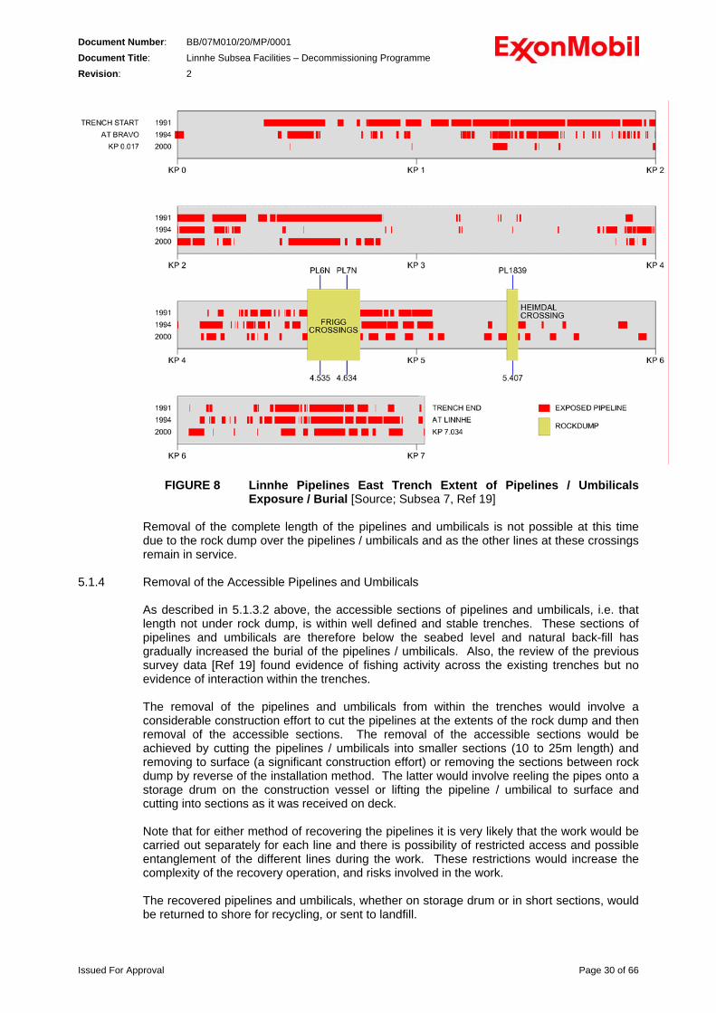
FIGURE 6 Linnhe Pipelines East Trench Depth [Source; Subsea 7, Ref 19] Although the pipelines and umbilicals were laid into the open trenches with no post-lay back-fill or burial, there has been extensive natural back-fill and burial of the pipelines over the time since installation. During the last full survey, in 2000, the pipelines / umbilicals in the west trench were exposed in 26 sections [Ref 19], with exposed length totalling 426m (6.1% of pipeline length). The 2000 survey found the lines in the east trench to be exposed in 56 sections, with exposed length totalling 1,617m (23.0% of pipeline length). Figures 7 and 8 illustrate the extent of exposure of the pipelines / umbilicals in the West and East trenches respectively as recorded in the surveys of 1991, 1994 and 2000.
FIGURE 7 Linnhe Pipelines West Trench Extent of Pipeline Exposure [Source; Subsea 7, Ref 19]
Issued For Approval Page 29 of 66
Document Number: BB/07M010/20/MP/0001 Document Title: Linnhe Subsea Facilities – Decommissioning Programme Revision: 2
FIGURE 8 Linnhe Pipelines East Trench Extent of Pipelines / Umbilicals Exposure / Burial [Source; Subsea 7, Ref 19]
Removal of the complete length of the pipelines and umbilicals is not possible at this time due to the rock dump over the pipelines / umbilicals and as the other lines at these crossings remain in service.
5.1.4 Removal of the Accessible Pipelines and Umbilicals As described in 5.1.3.2 above, the accessible sections of pipelines and umbilicals, i.e. that length not under rock dump, is within well defined and stable trenches. These sections of pipelines and umbilicals are therefore below the seabed level and natural back-fill has gradually increased the burial of the pipelines / umbilicals. Also, the review of the previous survey data [Ref 19] found evidence of fishing activity across the existing trenches but no evidence of interaction within the trenches. The removal of the pipelines and umbilicals from within the trenches would involve a considerable construction effort to cut the pipelines at the extents of the rock dump and then removal of the accessible sections. The removal of the accessible sections would be achieved by cutting the pipelines / umbilicals into smaller sections (10 to 25m length) and removing to surface (a significant construction effort) or removing the sections between rock dump by reverse of the installation method. The latter would involve reeling the pipes onto a storage drum on the construction vessel or lifting the pipeline / umbilical to surface and cutting into sections as it was received on deck. Note that for either method of recovering the pipelines it is very likely that the work would be carried out separately for each line and there is possibility of restricted access and possible entanglement of the different lines during the work. These restrictions would increase the complexity of the recovery operation, and risks involved in the work. The recovered pipelines and umbilicals, whether on storage drum or in short sections, would be returned to shore for recycling, or sent to landfill.
Issued For Approval Page 30 of 66
Document Number: BB/07M010/20/MP/0001 Document Title: Linnhe Subsea Facilities – Decommissioning Programme Revision: 2
The removal work as described above would involve some relatively minor disturbance of the seabed within the trenches. However, the work would be intensive construction work involving technically difficult cutting and handling of pipeline and umbilical sections and would require several weeks of a diving construction vessel on-site. Additionally, the recovery operation would most likely result in discharge of the pipeline / umbilical contents to sea during the recovery works, refer also to section 5.3.1 below. It is considered that the removal of the accessible pipelines and umbilicals within the trenches would not be of overall benefit when considered in comparison to the increased safety risks and incremental environmental impact and disturbance caused by the significant deconstruction work required. However, further work may be carried out at those sections of pipelines / umbilicals at the Frigg and Vesterled / Heimdal crossings when the plans for decommissioning those pipelines become available and the potential for change to the condition of the Linnhe lines is understood,
5.2 Removal of Installation – Protection Structure 5.2.1 Removal Method Statement
The Protection Structure arrangement is shown in Figure 4, which is presented in Section 4.0 above. It is an open lattice structure of tubular steel, approximately 200 Te mass, secured in place by four piles. The proposed and preferred removal method is to remove the structure in its entirety; cutting the piles no less than 0.6m below seabed level. This would also involve cutting, or disconnecting, the pipelines and umbilical at the perimeter of the structure. In effect this would be the reverse of the installation method for the structure. Due to the availability of construction vessels, i.e. there are few heavy lift / construction vessels capable of single lift of around 200 Te mass, it is proposed that the structure will be cut into sections before removal. The structure contains no hydrocarbon or chemical materials and there is no record of and it is therefore assumed there is no NORM at Linnhe Field; refer to section 5.3 below for details of the pipelines and umbilicals. The wells have previously been removed and no grout build up has been previously noted around the structure; refer to section 7 below for details of the drill cuttings at Linnhe Field. The securing of the piles to the structure was via a mechanical lock system, Hydrolok, and grouting of the piles was not carried out. Therefore, the removal of the structure will not involve any loose or mobile materials that may be disturbed, dislodged or deposited by the removal operation. Cutting of piles, and well casings, is relatively common practice and several systems are commercially available; using HP water with entrained grit, conventional hydraulic saw or diamond-tipped wire. These tools can be deployed / operated by either ROV or diver, with open access to the cut location normally being the most important factor to allow ROV operation. It is likely that diving will be required for some of the removal works, especially given the restricted access to cut the piles and to remove the roof panels. The pile cutting operation will require some excavation of seabed and will result in a small, typically 1m diameter x 1m maximum depth, depression around the top of the remaining section of pile. The remaining pile section will be below the surrounding seabed. The seabed in the Linnhe area has been stable through the period since the structure was installed and therefore it can be expected to remain stable after removal. The depression at each pile will gradually in-fill over time similar to that already evident for the pipeline trenches, refer to section 5.1.3.2 above. It is considered this approach will mean that the pile sections terminating at no less than 0.6m below seabed will not affect other users of the Linnhe area following the pile cutting and removal operations.
Issued For Approval Page 31 of 66
Document Number: BB/07M010/20/MP/0001 Document Title: Linnhe Subsea Facilities – Decommissioning Programme Revision: 2
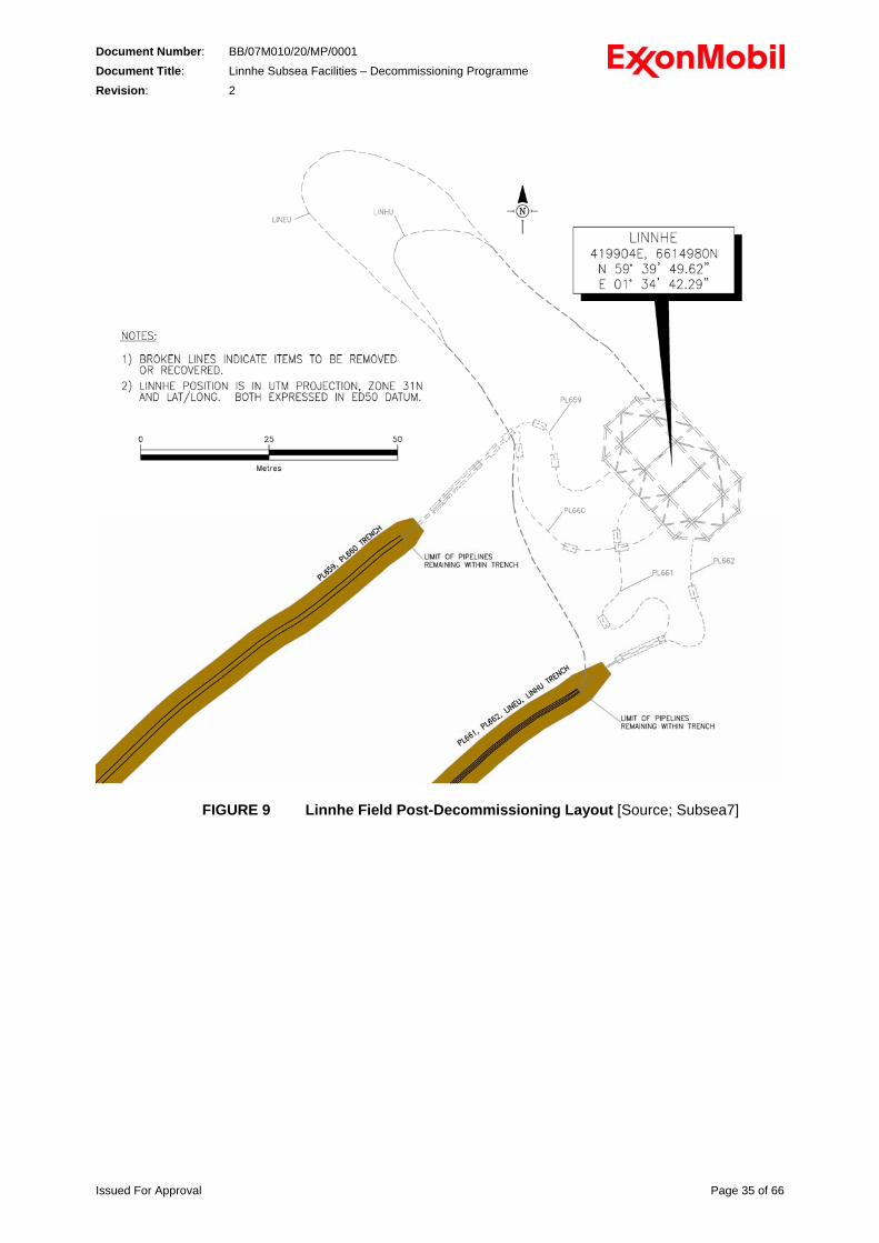
To remove the structure in sections it will be necessary to temporarily support the cut sections of the structure. These temporary supports will be recovered on completion of the decommissioning work. The lifting of the structure sections will replicate commonly used subsea construction procedures and operations. However, most lifting operations are of new equipment where the lift points, weight and overall structural integrity would be well understood and designed for the planned use. Lifting of equipment after some period on the seabed introduces risks from the unknown structural integrity condition and uncertainty of the actual mass. Therefore, detailed engineering shall focus on understanding these uncertainties to reduce the risk from the operation. The detailed engineering will also consider the risks from the transfer of the structure from the crane onto the deck of the vessel. If lifted as a single piece, the structure could be placed on deck to stand on the cut-off legs / piles, which may be different heights or may damage the deck. If the structure is removed in sections then these are unlikely to be of a geometry to be placed on deck without additional support. It is expected that some grillage (deck strengthening frame) would be used to support the structure on deck and to provide seafastening and this would include plates and / or tubes to prevent movement once the structure was on deck. This type of arrangement is commonly used in subsea construction works and would be defined during detailed engineering. Although there is no record of NORM in Linnhe Field, the recovered sections of structure and piles will be checked for the presence of NORM on the deck of the construction vessel and appropriate protective / containment measures taken dependent on the presence and concentration of any NORM found. Authorisation for disposal of the recovered materials will be sought from SEPA should the concentration of NORM be found to be greater than defined in Schedule 1 of the Radioactive Substances Act 1993. On completion of the removal works, including recovery of temporary materials, a survey of the seabed would be made to confirm the as-left status and seabed topography. The as-left status shall be similar to that illustrated in Figure 9, presented below.
5.2.2 Onshore Recycling / Disposal On completion of the recovery of the Protection Structure and Piles, as described above, the materials shall be taken to shore and transferred to an experienced contractor who would take receipt of the materials for recycling. The Protection Structure and Piles are structural carbon steel and the anodes are Al-Zn alloy; both are readily and regularly recycled. If required, authorisation for disposal of the recovered materials will be sought from SEPA should the concentration of NORM associated with the recovered materials be found to be greater than defined in Schedule 1 of the Radioactive Substances Act 1993.
Issued For Approval Page 32 of 66
Document Number: BB/07M010/20/MP/0001 Document Title: Linnhe Subsea Facilities – Decommissioning Programme Revision: 2 5.3 Removal of Pipelines and Umbilicals
5.3.1 Partial Removal Method Statement
The previous work in Linnhe Field in preparation for decommissioning, refer to section 3.2.2 above, resulted in the pipelines and hydraulic / chemical umbilical being left filled with seawater, dosed with inhibition chemicals. At Linnhe Field, each 6” carbon steel pipeline is connected to an isolation valve and flexible jumpers connect to the piping within the Protection Structure. The isolation valves are housed in two valve protection structures. Various stabilisation / protection concrete mattresses and sand / grout bags have been placed over the pipelines and umbilicals. The proposed and preferred removal method is to cut the pipelines near the ends of the trenches and recover the pipelines between this cut and the disconnection made at the Protection Structure. The valves, associated protection structures and all concrete mattresses and sand/grout bags shall be recovered during this work. Caps will be fitted to the pipelines to prevent future leakage of the contents. Similarly, the umbilicals will be cut in the trenches and the extent of umbilical up to the Protection Structure recovered; plugs will be installed in the hydraulic / chemical umbilical cores to prevent future inhibited seawater leakage. The proposed and preferred removal method does not include further flushing of the pipelines to reduce the level of residual hydrocarbon, particularly of the Production Pipeline PL659 which was flushed previously, as described in section 3.2.2 above, leaving it filled with treated seawater and <2000ppm hydrocarbon content. The only pipeline currently connected to Beryl Bravo is Water Injection, and there is no loop at Linnhe to enable flushing, Flushing the pipeline(s) would involve significant construction work requiring construction vessel(s), spoolpiece installation (and removal), pumping and liquid treatment / disposal. There are several methods that could be used to execute this flush, i.e. one vessel at either end of the pipeline, one vessel and a loop at Linnhe (or Bravo) or connect to Beryl Bravo and loop at Linnhe, but they all require the significant activities described above. The trenches, and pipelines / umbilicals within the trenches, have been stable in the period since construction, in 1990, and can reasonably be expected to remain so for the foreseeable future with the exception of outside interference. Over the coming years, the pipelines shall corrode as the cathodic protection system (sacrificial anodes) deteriorates in line with its original design life. The deterioration of the pipelines is extremely unlikely to affect their position within the trenches, or the interaction with other users of the sea. As the pipe wall corrodes through-wall the contents will be open to the seabed. However, as in-fill of the trenches has been increasing since installation, the gradual discharge of the pipeline contents will travel through the seabed sediment before reaching the seabed surface. Discharge is also likely to be gradual over a period of years as the pipeline contents are stagnant, in equilibrium and corrosion will be localised at first, slowly spreading along the pipeline. To flush the pipeline would, as described above, involve construction work and while environmental impacts from the construction work would not be significant there are aspects of the flushing that require sensitive management to minimise the potential for environmental impact [Ref 24]. In addition, the flushing operation itself may stress the pipeline and cause accidental release of the pipeline contents into the environment. The flushing operation will result in an increase in the potential to adversely affect the environment and also increase the safety risks for the personnel involved in the construction work. The proposed method, to leave the pipeline contents as-found with no further flushing, is therefore considered the best option, although the hydrocarbon concentration in the seawater remaining in the production pipeline may exceed the level generally acceptable for seawater discharge.
Issued For Approval Page 33 of 66
Document Number: BB/07M010/20/MP/0001 Document Title: Linnhe Subsea Facilities – Decommissioning Programme Revision: 2
The cutting and recovery operations will result in discharge of some of the contents of the pipelines and umbilicals. This will be a discharge of seawater with less than 2000ppm hydrocarbon and 500ppm TROS650, with the possibility of traces of RX-42 (wax solvent) and RX-07T (well cleaning solvent), which were used during the pipeline flushing, There is no record of NORM being produced from Linnhe Field. The cutting and recovery operation will be similar to that described for the Protection Structure, albeit of smaller size. The plugged pipeline ends within the trenches will be buried in the seabed, either by water-jetting the adjacent seabed to allow the pipes to self-bury or by dredging local to the trench and using the spoil to in-fill at the pipeline ends. The final status of the pipelines ends would be approximately 0.8m below adjacent seabed, i.e. trench depth, with around 300mm cover over the pipe ends. Although there is no record of NORM in Linnhe Field, the recovered sections of pipelines and umbilicals will be checked for the presence of NORM on the deck of the construction vessel and appropriate protective / containment measures taken dependent on the presence and concentration of any NORM found. Authorisation for disposal of the recovered materials will be sought from SEPA should the concentration of NORM be found to be greater than defined in Schedule 1 of the Radioactive Substances Act 1993. On completion of the removal works, including recovery of temporary materials, a survey will be made to confirm the as-left status of the seabed at the areas where the pipelines / umbilicals were removed. The as-left status shall be similar to that illustrated in Figure 8. The remaining sections of pipelines shall be subject to an ongoing monitoring regime; see section 11.2.3, and the Linnhe Owners, that have been served Notices under Section 29 of the Petroleum Act 1998, remain liable for the sections of pipelines remaining on the seabed.
5.3.2 Onshore Recycling / Disposal On completion of the recovery of the Pipelines and umbilical sections, as described above, the materials shall be taken to shore and transferred to an experienced contractor who would take receipt of the materials for recycling. The bulk of the material is carbon steel, which is both readily and regularly recycled. Recycling of some of the materials, such as the hydraulic / chemical umbilical and the flexible jumpers, may not be efficient due to their construction, so these may be disposed of in land-fill or other method. It is expected that the recovered concrete mattresses and sand / grout bags are not suitable for recycling and therefore will be disposed in land-fill. If required, authorisation for disposal of the recovered materials will be sought from SEPA should the concentration of NORM associated with the recovered materials be found to be greater than defined in Schedule 1 of the Radioactive Substances Act 1993. It is envisaged that the recycling and disposal shall be in UK and if this is not to be the case then consent and authorisation shall be sought under the Transfrontier Shipment of Waste Regulations 1994 prior to commencing the decommissioning works.
Issued For Approval Page 34 of 66
Document Number: BB/07M010/20/MP/0001 Document Title: Linnhe Subsea Facilities – Decommissioning Programme Revision: 2
FIGURE 9 Linnhe Field Post-Decommissioning Layout [Source; Subsea7]
Issued For Approval Page 35 of 66
Document Number: BB/07M010/20/MP/0001 Document Title: Linnhe Subsea Facilities – Decommissioning Programme Revision: 2 6.0 WELLS
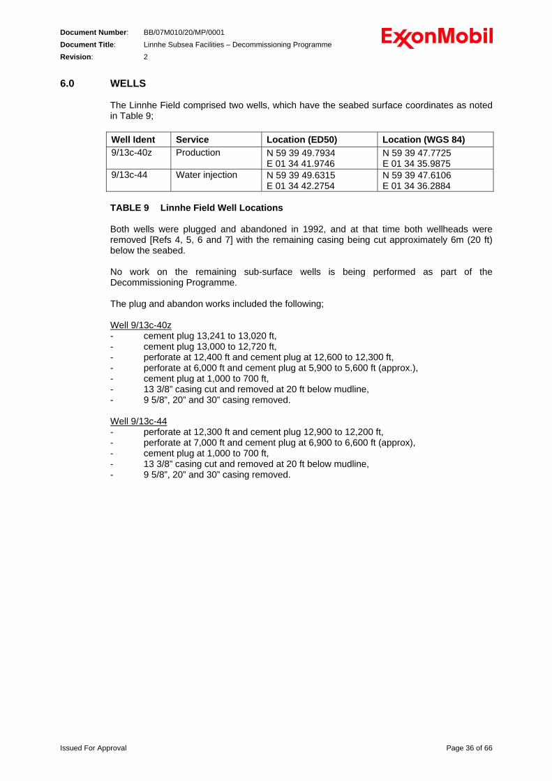
The Linnhe Field comprised two wells, which have the seabed surface coordinates as noted in Table 9; Well Ident Service Location (ED50) Location (WGS 84) 9/13c-40z Production N 59 39 49.7934
E 01 34 41.9746 N 59 39 47.7725 E 01 34 35.9875
9/13c-44 Water injection N 59 39 49.6315 E 01 34 42.2754
N 59 39 47.6106 E 01 34 36.2884
TABLE 9 Linnhe Field Well Locations Both wells were plugged and abandoned in 1992, and at that time both wellheads were removed [Refs 4, 5, 6 and 7] with the remaining casing being cut approximately 6m (20 ft) below the seabed. No work on the remaining sub-surface wells is being performed as part of the Decommissioning Programme. The plug and abandon works included the following; Well 9/13c-40z- cement plug 13,241 to 13,020 ft, - cement plug 13,000 to 12,720 ft, - perforate at 12,400 ft and cement plug at 12,600 to 12,300 ft, - perforate at 6,000 ft and cement plug at 5,900 to 5,600 ft (approx.), - cement plug at 1,000 to 700 ft, - 13 3/8” casing cut and removed at 20 ft below mudline, - 9 5/8”, 20” and 30” casing removed.
Well 9/13c-44 - perforate at 12,300 ft and cement plug 12,900 to 12,200 ft, - perforate at 7,000 ft and cement plug at 6,900 to 6,600 ft (approx), - cement plug at 1,000 to 700 ft, - 13 3/8” casing cut and removed at 20 ft below mudline, - 9 5/8”, 20” and 30” casing removed.
Issued For Approval Page 36 of 66
Document Number: BB/07M010/20/MP/0001 Document Title: Linnhe Subsea Facilities – Decommissioning Programme Revision: 2 7.0 DRILL CUTTINGS
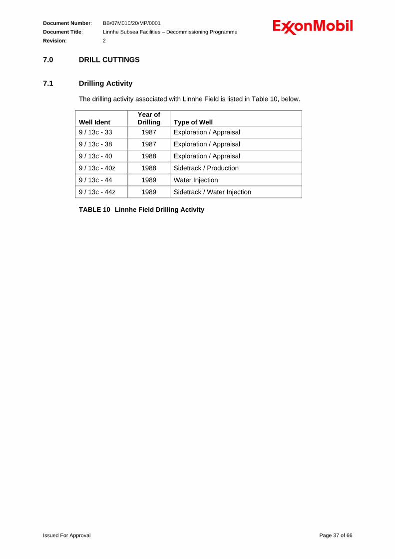
7.1 Drilling Activity
The drilling activity associated with Linnhe Field is listed in Table 10, below. Well Ident
Year of Drilling
Type of Well
9 / 13c - 33 1987 Exploration / Appraisal
9 / 13c - 38 1987 Exploration / Appraisal
9 / 13c - 40 1988 Exploration / Appraisal
9 / 13c - 40z 1988 Sidetrack / Production
9 / 13c - 44 1989 Water Injection
9 / 13c - 44z 1989 Sidetrack / Water Injection TABLE 10 Linnhe Field Drilling Activity
Issued For Approval Page 37 of 66
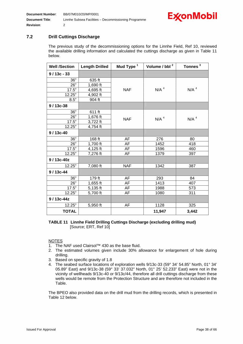
Document Number: BB/07M010/20/MP/0001 Document Title: Linnhe Subsea Facilities – Decommissioning Programme Revision: 2 7.2 Drill Cuttings Discharge
The previous study of the decommissioning options for the Linnhe Field, Ref 10, reviewed the available drilling information and calculated the cuttings discharge as given in Table 11 below. Well /Section Length Drilled Mud Type 1 Volume / bbl 2 Tonnes 3
9 / 13c - 33
36” 635 ft 26” 1,690 ft
17.5” 4,695 ft 12.25” 4,902 ft
8.5” 904 ft
NAF N/A 4 N/A 4
9 / 13c-38
36” 611 ft 26” 1,676 ft
17.5” 3,722 ft 12.25” 4,754 ft
NAF N/A 4 N/A 4
9 / 13c-40
36” 168 ft AF 276 80 26” 1,700 ft AF 1452 418
17.5” 4,125 ft AF 1596 460 12.25” 7,276 ft AF 1379 397
9 / 13c-40z
12.25” 7,080 ft NAF 1342 387 9 / 13c-44
36” 179 ft AF 293 84 26” 1,655 ft AF 1413 407
17.5” 5,135 ft AF 1988 573 12.25” 5,700 ft AF 1080 311
9 / 13c-44z
12.25” 5,950 ft AF 1128 325 TOTAL 11,947 3,442
TABLE 11 Linnhe Field Drilling Cuttings Discharge (excluding drilling mud)
[Source; ERT, Ref 10]
NOTES 1. The NAF used Clairsol™ 430 as the base fluid. 2. The estimated volumes given include 30% allowance for enlargement of hole during
drilling. 3. Based on specific gravity of 1.8 4. The seabed surface locations of exploration wells 9/13c-33 (59° 34’ 54.85” North, 01° 34’
05.89” East) and 9/13c-38 (59° 33’ 37.032” North, 01° 25’ 52.233” East) were not in the vicinity of wellheads 9/13c-40 or 9/13c/44, therefore all drill cuttings discharge from these wells would be remote from the Protection Structure and are therefore not included in the Table.
The BPEO also provided data on the drill mud from the drilling records, which is presented in Table 12 below.
Issued For Approval Page 38 of 66
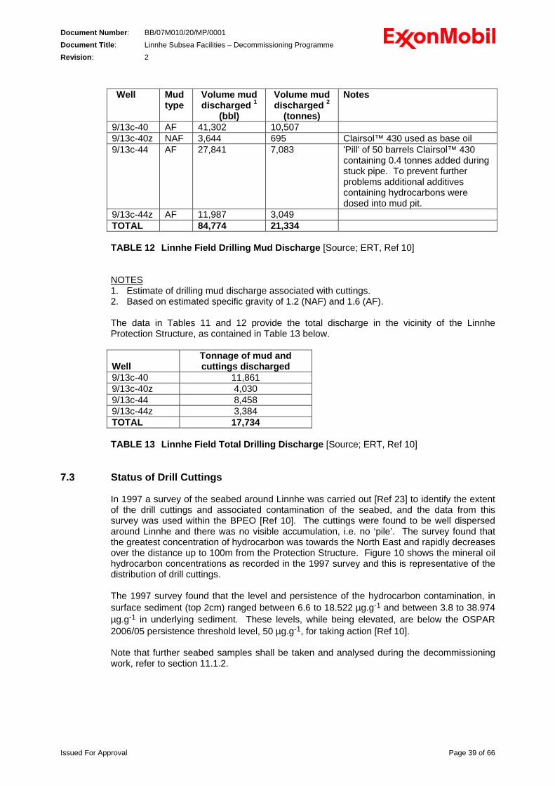
Document Number: BB/07M010/20/MP/0001 Document Title: Linnhe Subsea Facilities – Decommissioning Programme Revision: 2
Well
Mud type
Volume mud discharged 1
(bbl)
Volume mud discharged 2
(tonnes)
Notes
9/13c-40 AF 41,302 10,507 9/13c-40z NAF 3,644 695 Clairsol™ 430 used as base oil 9/13c-44 AF 27,841 7,083 'Pill' of 50 barrels Clairsol™ 430
containing 0.4 tonnes added during stuck pipe. To prevent further problems additional additives containing hydrocarbons were dosed into mud pit.
9/13c-44z AF 11,987 3,049 TOTAL 84,774 21,334 TABLE 12 Linnhe Field Drilling Mud Discharge [Source; ERT, Ref 10] NOTES 1. Estimate of drilling mud discharge associated with cuttings. 2. Based on estimated specific gravity of 1.2 (NAF) and 1.6 (AF).
The data in Tables 11 and 12 provide the total discharge in the vicinity of the Linnhe Protection Structure, as contained in Table 13 below.
Well
Tonnage of mud and cuttings discharged
9/13c-40 11,861 9/13c-40z 4,030 9/13c-44 8,458 9/13c-44z 3,384 TOTAL 17,734 TABLE 13 Linnhe Field Total Drilling Discharge [Source; ERT, Ref 10]
7.3 Status of Drill Cuttings In 1997 a survey of the seabed around Linnhe was carried out [Ref 23] to identify the extent of the drill cuttings and associated contamination of the seabed, and the data from this survey was used within the BPEO [Ref 10]. The cuttings were found to be well dispersed around Linnhe and there was no visible accumulation, i.e. no ‘pile’. The survey found that the greatest concentration of hydrocarbon was towards the North East and rapidly decreases over the distance up to 100m from the Protection Structure. Figure 10 shows the mineral oil hydrocarbon concentrations as recorded in the 1997 survey and this is representative of the distribution of drill cuttings. The 1997 survey found that the level and persistence of the hydrocarbon contamination, in surface sediment (top 2cm) ranged between 6.6 to 18.522 µg.g-1 and between 3.8 to 38.974 µg.g-1 in underlying sediment. These levels, while being elevated, are below the OSPAR 2006/05 persistence threshold level, 50 µg.g-1, for taking action [Ref 10]. Note that further seabed samples shall be taken and analysed during the decommissioning work, refer to section 11.1.2.
Issued For Approval Page 39 of 66
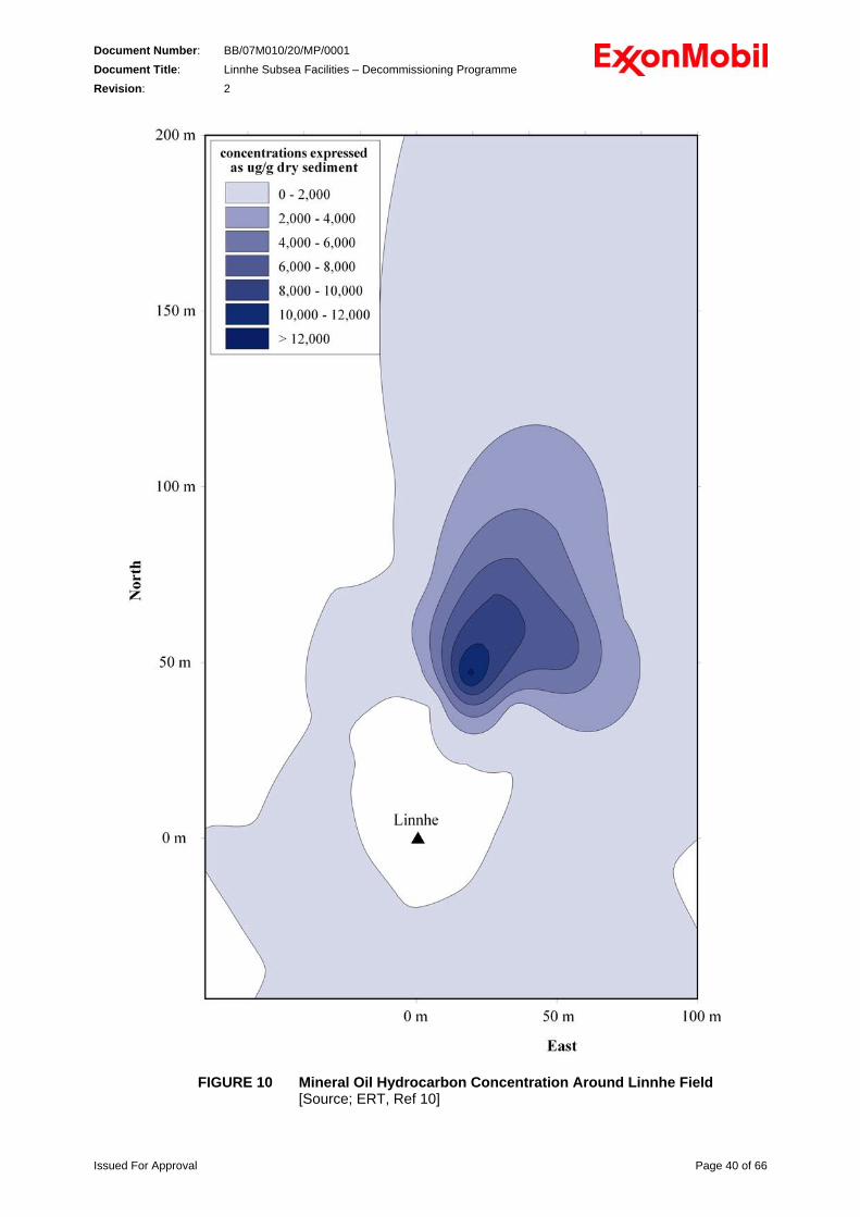
Document Number: BB/07M010/20/MP/0001 Document Title: Linnhe Subsea Facilities – Decommissioning Programme Revision: 2
FIGURE 10 Mineral Oil Hydrocarbon Concentration Around Linnhe Field [Source; ERT, Ref 10]
Issued For Approval Page 40 of 66
Document Number: BB/07M010/20/MP/0001 Document Title: Linnhe Subsea Facilities – Decommissioning Programme Revision: 2 8.0 ENVIRONMENTAL IMPACT ASSESSMENT
A BPEO Analysis was carried out for decommissioning the Linnhe Subsea Facility in 1998; Ref 10, and this has been used as the basis for the Environmental Impact Assessment, (EIA) undertaken by Xodus and detailed in Ref 21, including the summary Environmental Statement presented below. During the EIA process the potential impacts of the Linnhe Field decommissioning project on the environment were identified and considered. Overall it is considered that the project will not have any significant impacts (project specific or cumulative) on the environment.
ENVIRONMENTAL STATEMENT 8.1 Introduction
This Environmental Statement (ES) summarises the EIA process undertaken as required under the Offshore Petroleum Production and Pipelines (Assessment of Environmental Effects) Regulations 1999 for the proposed decommissioning project of the Linnhe Field by MNS. The Linnhe Field is located in Block 9/13c at about 160 km to the east of the southern tip of Shetland in approximately 123 metres of water. The field lies 7.5 km north-east of the Beryl Bravo platform and was a 'fast track' development which consisted of one production and one injection well tied back to the Beryl Bravo platform. Production at the field commenced in August 1989 and the field produced for 2 years.
8.2 Environmental Description 8.2.1 Physical Environment
The topography of the seabed around the Linnhe subsea development is predominantly flat and of low relief. The current regime in the location of the field is typical of the northern North Sea, with relatively homogenous current velocities at surface, midwater and seabed, and consists of a weak tidal and a larger non-tidal component (maximum velocities of up to 0.3 m/s (0.6 knots) on spring tides and 0.15 m/s (0.3 knots) for neap tides). Linnhe Field is located in an area that is likely to be affected by two water masses: Atlantic water and northern North Sea water. The monthly mean surface temperature in the northern North Sea is in the range of 6-9 °C in February and 13.5-14 °C in August. The monthly mean bottom temperature for the area ranges between 7-8 °C throughout the year. Mean surface salinity in the Linnhe area ranges between 35.2 and 35.3‰ in winter to 35.0 and 34.75‰ in summer. Little difference exists between the mean bottom salinity in the northern North Sea in winter and summer (mean salinity of 35.2 ‰). Meteorological data for the northern North Sea (which is considered representative of conditions at the Linnhe location) from the 1950-2001 period show the occurrence of winds from all directions, although winds from south-southwest to south-southeast are predominant. Air temperature data for the northern North Sea indicate a mean monthly range from 4°C to 7°C in winter and a mean temperature of up to 14.3°C during the summer. Visibility in the Linnhe area is generally good throughout the year, averaging approximately 13 km.
Issued For Approval Page 41 of 66

Document Number: BB/07M010/20/MP/0001 Document Title: Linnhe Subsea Facilities – Decommissioning Programme Revision: 2
The permitted discharge of cleaned drill cuttings at Linnhe has resulted in an area of contamination and disturbance on the seabed (cuttings pile). The highest sediment hydrocarbon concentrations associated with the cuttings was, at the time of the survey in 1997 [Ref 10], 18,522µg.g-1 in surface sediment (top 2cm) and 38,974µg.g-1 on underlying sediment (concentration of hydrocarbon in dry sediment). This represents an elevated level of hydrocarbon concentration in comparison to the background level of 6.6µg.g-1 in surface sediment and 3.8µg.g-1 on underlying sediment. Nevertheless, the maximum hydrocarbon concentration observed around Linnhe lies within the lower range of concentrations observed during the UKOAA Joint Industry Project on drill cuttings piles, and is also below the OSPAR 2006/5 recommended persistence level of 50 µg.g-1.
8.2.2 Biological Environment
Benthic fauna in the area of the Linnhe Field are typical of the northern North Sea. The biodiversity in the immediate vicinity of the cuttings pile is reduced in comparison with non-impacted sediment and exhibits a benthic community assemblage typical to an organically enriched environment. The planktonic assemblage in the region of the Linnhe area is mainly made up of northern intermediate (mixed water) and neritic (coastal water) species. The dominant phytoplankton species in the North Sea is the dinoflagellate Ceratia, while zooplankton is dominated by the copepods Calanus finmarchicus and C. helgolandicus. The Linnhe Field is a spawning ground for haddock (February to May), saithe (January to April) and Norway pout (February to June). Haddock, blue whiting and mackerel also use the area as a nursery ground. Although there is fish spawning and nursery activity in the vicinity of the Linnhe Field at certain times of the year, the spawning and nursery areas are part of larger offshore areas. Within the vicinity of the Linnhe area, seabird densities appear to be low overall, with fulmar and guillemot being the most abundant species. The vulnerability of seabird species to surface pollution shows that the Linnhe area is classified as a very high vulnerability area only during the month of October. The most abundant cetacean in the Linnhe area is the harbour porpoise. However, this species appears to be widespread across the northern and central North Sea, with important populations outside the Linnhe area. In view of the distribution of common and grey seal species, it should be assumed that both species may be encountered in the Linnhe area; although it should be noted that the movements of these animals outside of the breeding seasons are not well known.
8.2.3 Commercial Fisheries and Other Sea Users Demersal fishing effort in the Linnhe area, from UK vessels landing in the UK, is classed as medium, with the total value of all demersal landings from these vessels classed as high. The level of pelagic fishing effort in the Linnhe area is classed as low, with the total value of all pelagic landings from these vessels, classed as high. (Overall fishing effort at the Linnhe area is dominated by UK vessels.) The northern North Sea is an area of extensive offshore oil and gas activity and these are the fields in the immediate vicinity of the Linnhe Protection Structure: Beryl, Ness and Nevis (MNS), Bruce (BP) and Peik (Total). Around the Linnhe area the COAST database indicates shipping activity is mainly limited to specific oil and gas industry traffic. No designated submarine exercise grounds or known areas of military activity lie in the vicinity of the Linnhe area.
Issued For Approval Page 42 of 66
Document Number: BB/07M010/20/MP/0001 Document Title: Linnhe Subsea Facilities – Decommissioning Programme Revision: 2
8.2.4 Conservation Interest
Following studies of the Beryl area and consultation with statutory authorities, it has been confirmed that the seabed falling within the definitions of the Habitats Directive in the vicinity of the Beryl platforms are not unique and are therefore not expected to be highlighted for conservation and protection. The closest draft offshore SACs to the Linnhe field is the Braemar pockmark (situated 75 km to the south) and the Scanner pockmark (situated 160 km to the south). The nearest offshore SAC site is the Moray Firth located approximately 350 km to the south west of the Linnhe field.
8.3 EIA Process and Methodology
The conclusion reached in the BPEO analysis for the Linnhe Field decommissioning programme report was used as a base to identify and rank all potential environmental issues (including interactions with other sea users) associated with the Linnhe decommissioning project. Following the selection of a decommissioning option, the issues associated with the chosen solution that ranked as of negligible or minor significance were screened out. The remaining issues were carried forward for further assessment. MNS tended to remove or reduce such issues through various mitigation and management measures identified in order to reduce the environmental risk. The main issues identified for further consideration include: • Atmospheric emissions;
• Interference with other shipping activities;
• Seabed disturbance;
• Chemical discharge;
• Oily water discharge;
• Waste to landfill; and
• Associated accidental events. 8.4 Atmospheric Emissions 8.4.1 Introduction
There has been considerable increase in public attention on pollution of the atmosphere with consequent threats to both natural ecosystems and human well-being. This attention focuses on potential effects at three levels: local and national, transboundary (North Sea) and global. The major source of atmospheric emissions from offshore operations is the combustion of fuel, both fuel gas and diesel in the generation of power. The atmospheric emissions associated with the Linnhe Field Decommissioning Project is reviewed in this ES. The atmospheric emissions of the project will be: • Offshore emissions associated with the retrieval of the structure and pipelines; and
• Onshore emissions relating to the recycling and disposal of the removed materials to landfill.
Issued For Approval Page 43 of 66
Document Number: BB/07M010/20/MP/0001 Document Title: Linnhe Subsea Facilities – Decommissioning Programme Revision: 2
An estimate of the emissions of the onshore activities cannot be calculated, as the onshore treatment of the Linnhe structure contract has not yet been put to tender and no detailed inventory of what can be recycled is available (this will be an outcome of the detailed engineering). Nevertheless, it is important to note that most of the onshore emissions will be associated with the recycling and landfilling of the removed materials and that the waste contractor will have accounted for these emissions.
8.4.2 Marine Vessels Emissions The marine vessel emissions have been assessed for the two removal options: • Single lift: using a DSV and a heavy lift vessel; and
• Piecemeal: using a DSV and a supply vessel. Although the temporary increase in vessel presence will give rise to increased emissions, these will be relatively short-term and localised. The dispersive wind regime of the Linnhe area will ensure rapid dispersion of any atmospheric pollutants associated with the vessels. CO2 emissions from the decommissioning project represents approximately 0.012% (single lift option) and 0.007% (piecemeal option) of the total CO2 emissions on the UKCS from offshore oil and gas activities (based on 2005 data). The incremental contribution of the Linnhe decommissioning project to regional and global emissions is therefore insignificant. With the very brief time spent near the Scottish Northeast coast, the distance from the UK and European mainland’s and the strongly dispersive regime of the area, it is not expected that atmospheric emissions from the Linnhe decommissioning project activities will have detrimental impacts on the local environment. Although located close the UK-Norway median line, no significant transboundary impacts are anticipated.
8.5 Interference with Other Shipping Activities 8.5.1 Introduction
There is a very unlikely possibility that the mobilised vessels for the Linnhe decommissioning operation might interfere with the normal shipping activities at the Linnhe location by remaining in the vicinity of the Linnhe area for up to 17 days.
8.5.2 Shipping Activities Disturbance It has been established that on average 3 to 4 ships a day are passing in the vicinity of the Beryl Field. The great majority of the overall ships activity (81%) was related to the Oil and Gas industry (mostly infield vessels). MNS has in place a Marine Operation Manual (MOM) which forms the basis for management of all in-field (Beryl Area) marine operation. Via the MOM, MNS personnel are made aware of potential issues when conducting an operation at sea and of the associated remediation procedure. The MOM also presents the procedure to follow for the safe and efficient mobilisation, the management and operation of all vessels on contract to MNS. Finally, the MOM provides instructions to the Vessel Masters to reduce the risks identified with each task that might be undertaken on board the vessel. Furthermore, MNS has in place a ship collision risk management system (involving continuous vessel presence monitoring by radars and an alarms system to warn vessel that might be at risk) in the Beryl field vicinity (covering the Linnhe area). As the possible shipping activities disturbance will only be short term (17 days maximum), that most activities in the area are related to MNS work and that sufficient systems are in
Issued For Approval Page 44 of 66
Document Number: BB/07M010/20/MP/0001 Document Title: Linnhe Subsea Facilities – Decommissioning Programme Revision: 2
place to avoid any direct vessel incident, it is believed that the interference with other shipping activities represents only a minor risk.
8.6 Drill Cuttings Accumulation Disturbance 8.6.1 Introduction
During the removal phase of the Linnhe Field decommissioning project, a large amount of work is required to be carried out at or near the accumulated drill cuttings, which are well dispersed over the seabed to the North of Linnhe, refer to Figure 10 above. Through cutting operations (cutting the piles and structure), lifting operations and diver support there is potential for disturbing the accumulated Linnhe drill cuttings.
8.6.2 Cuttings Disturbance
In order to minimise disturbance of the cuttings when cutting the four piles ‘anchoring’ the Linnhe Protection Structure, an IPC system will be used. As the piles are to be cut no less than 0.6 m below seabed, a small amount of sediment around the piles will be disturbed and it is possible that a very small caving effect may occur. Should it prove necessary to remove the wellhead Protection Structure using the piecemeal removal solution, the Linnhe Protection Structure will be cut in pieces that can safely be retrieved. These cutting operations will require either divers and/or ROVs present near or on the accumulated cuttings. This will increase sediment movement and water column turbidity, and subsequently redeposition of the cuttings will occur. In order to minimise the impact of these operations, it is planned to use ROVs as much as technically possible and safe to do so. Should the structure be removed using the piecemeal technique, a temporary supporting structure will be required. Building and then removing the structure will present the same impacts as the above operations. Recovering the structure will disturb the surface layer of the cuttings. It will also increase the turbidity and to a smaller extent increase mixing of the water column. These disturbances are on a much smaller scale than the previously presented disturbances for the cutting operations and their effects will be highly localised and extremely short term. Disturbance to the cuttings could lead to resuspension and release of contaminants into the surrounding water. This produces the possibility of contaminants entering into the marine food chain through ingestion by marine life. It is expected that, although the effects of any cuttings pile disturbance would be undesirable, they are likely to be minor impacts that would be short-lived and localised. In addition, impacts on benthic biota living close to the Protection Structure are unlikely to be significant or long lasting as species present will have already been exposed to and will be tolerant of elevated levels of contaminants. It is therefore considered that the potential disturbance of the cuttings represents only a minor risk. For the same reasons as above plus the fact that there are no habitats of conservation interest in the vicinity of Linnhe Field, cumulative impacts are considered minor. Furthermore, following the removal of the Linnhe Protection Structure and before leaving the site, seabed samples will be collected. The analysis of these samples will be used to compare the 1997 state of the seabed and cuttings to the post decommissioning operation state. While taking sediment samples of the cuttings, a sidescan sonar or bathymetric survey may be performed to establish the present extent of the accumulated cuttings and seabed topography.
Issued For Approval Page 45 of 66
Document Number: BB/07M010/20/MP/0001 Document Title: Linnhe Subsea Facilities – Decommissioning Programme Revision: 2 8.7 Seabed Disturbance 8.7.1 Introduction
During the removal of the sections of the flowlines in the area of the Protection Structure, a large amount of work is required to be carried out at or near the seabed; and therefore through the cutting operations, lifting operations and diver support there is potential for seabed disturbance. Seabed disturbance associated with the vessels taking part in the Linnhe decommissioning project will not be discussed further as they will not use anchors.
8.7.2 Seabed Disturbance
To retrieve the flowlines that are outside the trenches, the exposed part of the flowlines will be cut at the start of the trenches and the cut ends buried by relocating seabed from the adjacent area. Cutting operations will require either divers and/or ROVs present near or at seabed level. This will increase sediment movement and water column turbidity, and subsequently redeposition of fine/light sediment. In order to minimise the impact of these operations, it is planned to use ROVs as much as technically possible and safe to do so. Lifting the flowlines, mattresses and sandbags will disturb the surface layer of the seabed. It will also increase the turbidity and to a smaller extent increase mixing of the water column. These disturbances are on a much smaller scale than the previously presented disturbances and their effects will be highly localised and extremely short term. It is expected that although the effects of seabed disturbance would be undesirable, there are likely to be minor impacts that would be short-lived and localised. In addition, impacts on benthic biota living in the Linnhe Field vicinity are unlikely to be significant or long lasting (as the benthic community in the Linnhe area is neither a typical nor a healthy northern North Sea benthic assemblage). It is therefore considered that the potential seabed disturbance represents only a minor risk. For the same reasons as above plus the fact that there are no habitats of conservation interest in the vicinity of Linnhe, cumulative impacts are considered minor.
8.8 Chemical Discharge 8.8.1 Introduction
Under the Offshore Chemicals Regulations 2002 (OCRs), operators require a permit to use and discharge chemicals. Operators need to assess the risks to the environment, which might arise from particular use and discharge. A formal process of risk assessment is required.
8.8.2 Chemical Discharge Should it prove necessary to remove the Linnhe Protection Structure using the piecemeal removal solution, the mix of biocide and oxygen scavenger that was added to the inside of the struts will be released to the marine environment. As the chemicals were added to the structure before its commissioning in 1989 (pre OCRs in 2002), no details have been kept on the specific biocide and oxygen scavenger that were used. It is therefore not possible to conduct a formal risk assessment. Nevertheless it is believed that the biocide and oxygen scavenger mix was an industry standard mix, such as TROS 650. In view of such low volume being discharged after such a prolonged time in the structure (18 years) the efficacy of the chemicals will have decreased. When the decreased efficacy is coupled with the immediate dilution and dispersion, the chemical discharge is considered unlikely to cause adverse effects on the marine environment.
Issued For Approval Page 46 of 66
Document Number: BB/07M010/20/MP/0001 Document Title: Linnhe Subsea Facilities – Decommissioning Programme Revision: 2
Following the flushing of the flowlines during the well abandonment operation of 1992, it is expected that the flowlines will contain traces of the biocide Drexel GXL, the oxygen scavenger Magcobar OS-7, the wax solvent RX-42 and the well cleaning chemical RX-07T. These chemicals are not covered by the OCR 2002 as the operation took part before chemical certification, and it is not possible to conduct a formal risk assessment of these chemicals. Nevertheless small volumes are being discharged and, after such a prolonged time in the flowlines (15 years) the efficacy of the chemicals will have decreased. The chemical discharge is therefore not likely to cause adverse effects on the marine environment. It is also expected that the pipeline hydrotest chemical TROS 650 will be present in the flowlines. As TROS 650 is registered on the current CEFAS list, it was decided to model its discharge using the latest CEFAS template to gain a better understanding of the effect associated with this discharge. Following modelling it was found that the discharge is not likely to cause adverse effects on the marine environment. No significant cumulative or transboundary impacts are expected with the discharge of chemicals from the Protection Structure and flowlines.
8.9 Oily Water Discharge 8.9.1 Introduction
During the initial pipeline abandonment work, before isolation, the production pipeline was cleaned via a series of flushes to a specification of a maximum oil in water content of 2000 ppm. With regards to the section of production pipeline being decommissioned, this is equivalent to total oily water discharge of 18.6m3, which equates to a maximum of 33 kg of hydrocarbon given an assumed maximum concentration of 2000ppm.
8.9.2 Oily Water Discharge
Following the initial cutting of the production pipeline, it is not expected that the content of the pipeline will spontaneously flow out as the system is not pressurised. It is envisaged that when the pipeline is cut into pieces that can safely be brought back to the surface, the oily water will then slowly seep through the open ends. The oily water will therefore be discharged in a few smaller isolated events at a slow rate. Oily water discharges may have the potential to impact marine life in the vicinity of the discharge point by way of intoxication. However, the more toxic aromatic hydrocarbons are both volatile and soluble, and may be absent given the elapsed time since the cleaning flushes. Any remaining aromatic hydrocarbons will be removed or rapidly diluted within the water column during the removal operation. Furthermore, studies have concluded that the risks to populations of ecologically or commercially important marine species do not appear to be significant. For these reasons and as it is an isolated event, the discharge of oily water is likely to have a minor impact that would be short-lived and localised. It is further expected that there will be no cumulative or transboundary effects. In addition to these, under the Offshore Petroleum Activities (Oil Pollution Prevention and Control) Regulations 2005 (OPPC), an OPPC permit will be sought. This will ensure that BERR is satisfied that the possible impacts from the oily water discharge are acceptable and have been minimised where possible.
Issued For Approval Page 47 of 66
Document Number: BB/07M010/20/MP/0001 Document Title: Linnhe Subsea Facilities – Decommissioning Programme Revision: 2 8.10 Waste to Landfill 8.10.1 Introduction
Once the Linnhe Protection Structure, associated flowlines, mattresses and sandbags are brought back on land they will be handed over to a waste contractor. Although it is intended to recycle as much of the material as possible, it is envisaged that it will not be possible for all recovered material to be recycled and therefore some material will have to be landfilled.
8.10.2 Waste to Landfill From all recovered material, it is envisaged that it will not be possible to successfully recycle the plastic hoses and steel armours of the umbilical, the recovered mattresses and sandbags, and the biofoul that will be removed from the surface of the structure. Therefore, following appropriate treatment, the above material will be disposed to landfill. The major impact from landfilling is the uptake of resources (i.e. land take). To reduce the rate of resources uptake, it is foreseen that the landfill site (to which the recovered material will be sent to) is already in existence. Furthermore, in order to maximise the reduction of resources uptake, it is the intention of MNS that the maximum amount of recovered material be sent for recycling (as much as is technically and financially viable to do so). It is therefore believed that because of the low volume of waste to landfill, landfilling of material will only represent a minor risk.
8.11 Accidental Events 8.11.1 Oil Spill
The only causes of oil spill would be incidents such as vessel grounding, collision or explosion resulting in total loss of cargo. The largest fuel inventories will be associated with the vessel’s fuel stored onboard (which is likely to be a mixture of heavy fuel oil and marine diesel). Nevertheless, from the historical data it is possible to affirm that the probability of such incidents for offshore vessels is extremely remote. As it is recognised that an oil spill could result in an environmental impact, MNS has a number of management control and mitigation measures in place to ensure that any impact is avoided or minimised. For instance, all vessels will comply with IMO/MCA codes for prevention of oil pollution, and will also have onboard Shipboard Oil Pollution Emergency Plans (SOPEPS). An approved Beryl Area specific Oil Spill Contingency Plan (OSCP) has been developed in accordance with the Merchant Shipping (Oil Pollution Preparedness, Response and Co-operation Convention) Regulations 1998. This details the actions to be taken in the event of a spill as well as the resources available to deal with it. Dispersants are available on the standby vessel and MNS is a member of Oil Spill Response Limited (OSRL). As discussed, the probability of an oil spill occurring is low and does not add significantly to the overall cumulative risk of a spill in the area. Although there are numerous species of seabird (including auks) in the vicinity of Linnhe, they are found in high numbers in January and July and in very high numbers in October only (the rest of the year in low or moderate numbers). As the operation is scheduled to take place outside the months when seabird numbers are high in the Linnhe area, no significant impacts are expected should an oil spill occur. Due to the relatively close proximity to the median line, it is appreciated that in the event of a large oil spill this could be expected to impact on the Norwegian sector although any impacts are not considered significant. The probability of an oil spill occurring is low, and therefore the overall risk of a transboundary impact is considered insignificant.
Issued For Approval Page 48 of 66
Document Number: BB/07M010/20/MP/0001 Document Title: Linnhe Subsea Facilities – Decommissioning Programme Revision: 2 8.11.2 Chemical Spill
The main factor causing loss of containment of chemicals is the technical failure of equipment, e.g. hose failure or leakage through loose fittings. Loss of containment will release into the environment minute volumes of contaminants. However, due to their inherent properties the release might be toxic, persistent or have low biodegradability in the marine environment (for instance surface cleaning chemicals might be toxic, dye in hydraulic fluid has a low biodegradability, etc.). The fates of chemicals in the environment are dependent on the partitioning of individual components between dissolved and particulate phases in the water column. Nevertheless, in the event of a spill the majority of contaminants are likely to be quickly dispersed in the deep waters of the environment posing little threat to the marine environment. Furthermore, MNS has response procedures in place in the event of a chemical spill. Although there are fish spawning in the vicinity of the Linnhe structure at certain times of the year, these areas are part of larger offshore breeding grounds; therefore, no significant impacts are expected should a loss of containment occur. The probability of a loss of containment event occurring is low and does not add significantly to the overall risk of a spill in the Beryl Bravo area.
8.11.3 Dropped Objects During the decommissioning operation objects will be lifted from seabed and around the vessel deck and may accidentally fall overboard. Measures will be taken to ensure that all deck items are securely stowed, that all lifting operations of materials from seabed to surface are undertaken in a safe and secure manner and should any over the side transfers become necessary that they are safely undertaken. Upon completion of the decommissioning operation, post project debris clearance and a survey will be undertaken; refer to section 11 below. The survey will be undertaken from the DSV and will cover the 500m zone around the site of the Linnhe structure. Should any debris be located, it will be recovered.
Issued For Approval Page 49 of 66
Document Number: BB/07M010/20/MP/0001 Document Title: Linnhe Subsea Facilities – Decommissioning Programme Revision: 2 8.12 Conclusion
During the EIA process the potential impacts of the Linnhe Field decommissioning project on the environment were identified and considered. Overall it is considered that the project will not have any significant impacts (project specific or cumulative) on the environment. Environmental impacts need to be minimised and appropriate management and mitigation measures have been recommended. In addition to these measures, the legal consents required to be in place for the project will ensure that all impacts and discharges are minimised where possible. In view of the fact that the Linnhe Field is close to the UK/Norway median line, possible transboundary impacts have be taken into account. The prevailing weather conditions and water circulation will reduce the possibility of direct transboundary impact to an insignificant level. No significant cumulative impacts are expected with the discharge of chemicals from the Protection Structure and flowlines, and from the discharge of oily water. It is expected that the effects of any seabed disturbance (including disturbance of cuttings pile) are likely to have minor impacts that would be short-lived and localised. Furthermore as there are no habitats of conservation interest in the vicinity of Linnhe, cumulative impacts associated with seabed disturbance are considered minor. Environmental management of the Linnhe Field decommissioning project has up to the point of ES submission been managed primarily through the application of the SHE Plan and the environmental assessment process. Environmental assessment, including consultation with stakeholders, is an iterative process and will continue beyond ES submission allowing for ongoing improvements in operational practice.
Issued For Approval Page 50 of 66
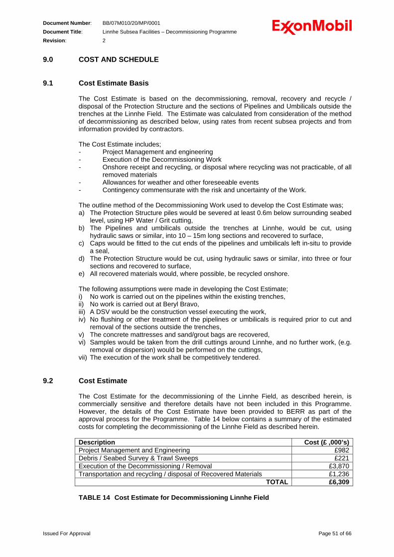
Document Number: BB/07M010/20/MP/0001 Document Title: Linnhe Subsea Facilities – Decommissioning Programme Revision: 2 9.0 COST AND SCHEDULE
9.1 Cost Estimate Basis
The Cost Estimate is based on the decommissioning, removal, recovery and recycle / disposal of the Protection Structure and the sections of Pipelines and Umbilicals outside the trenches at the Linnhe Field. The Estimate was calculated from consideration of the method of decommissioning as described below, using rates from recent subsea projects and from information provided by contractors. The Cost Estimate includes; - Project Management and engineering - Execution of the Decommissioning Work - Onshore receipt and recycling, or disposal where recycling was not practicable, of all
removed materials - Allowances for weather and other foreseeable events - Contingency commensurate with the risk and uncertainty of the Work. The outline method of the Decommissioning Work used to develop the Cost Estimate was; a) The Protection Structure piles would be severed at least 0.6m below surrounding seabed
level, using HP Water / Grit cutting, b) The Pipelines and umbilicals outside the trenches at Linnhe, would be cut, using
hydraulic saws or similar, into 10 – 15m long sections and recovered to surface, c) Caps would be fitted to the cut ends of the pipelines and umbilicals left in-situ to provide
a seal, d) The Protection Structure would be cut, using hydraulic saws or similar, into three or four
sections and recovered to surface, e) All recovered materials would, where possible, be recycled onshore. The following assumptions were made in developing the Cost Estimate; i) No work is carried out on the pipelines within the existing trenches, ii) No work is carried out at Beryl Bravo, iii) A DSV would be the construction vessel executing the work, iv) No flushing or other treatment of the pipelines or umbilicals is required prior to cut and
removal of the sections outside the trenches, v) The concrete mattresses and sand/grout bags are recovered, vi) Samples would be taken from the drill cuttings around Linnhe, and no further work, (e.g.
removal or dispersion) would be performed on the cuttings, vii) The execution of the work shall be competitively tendered.
9.2 Cost Estimate
The Cost Estimate for the decommissioning of the Linnhe Field, as described herein, is commercially sensitive and therefore details have not been included in this Programme. However, the details of the Cost Estimate have been provided to BERR as part of the approval process for the Programme. Table 14 below contains a summary of the estimated costs for completing the decommissioning of the Linnhe Field as described herein. Description Cost (£ ,000’s)Project Management and Engineering £982 Debris / Seabed Survey & Trawl Sweeps £221 Execution of the Decommissioning / Removal £3,870 Transportation and recycling / disposal of Recovered Materials £1,236
TOTAL £6,309 TABLE 14 Cost Estimate for Decommissioning Linnhe Field
Issued For Approval Page 51 of 66
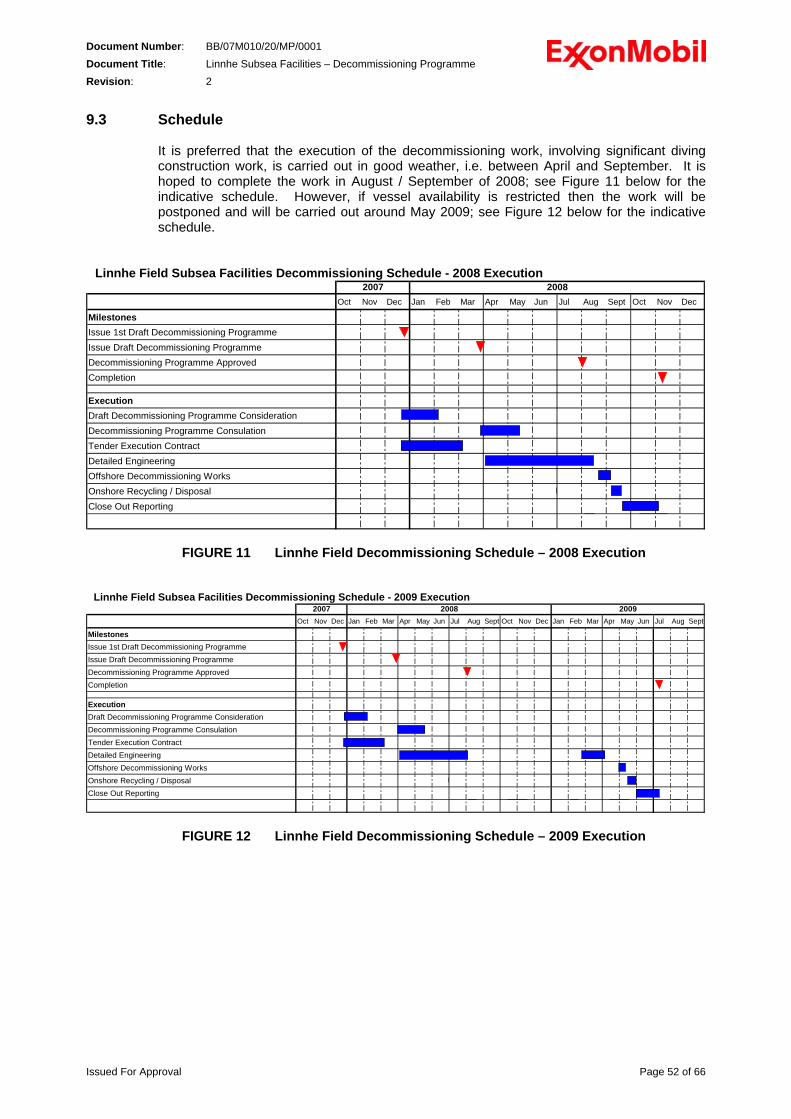
Document Number: BB/07M010/20/MP/0001 Document Title: Linnhe Subsea Facilities – Decommissioning Programme Revision: 2 9.3 Schedule
It is preferred that the execution of the decommissioning work, involving significant diving construction work, is carried out in good weather, i.e. between April and September. It is hoped to complete the work in August / September of 2008; see Figure 11 below for the indicative schedule. However, if vessel availability is restricted then the work will be postponed and will be carried out around May 2009; see Figure 12 below for the indicative schedule.
Linnhe Field Subsea Facilities Decommissioning Schedule - 2008 Execution
Oct Nov Dec Jan Feb Mar Apr May Jun Jul Aug Sept Oct Nov Dec
MilestonesIssue 1st Draft Decommissioning ProgrammeIssue Draft Decommissioning ProgrammeDecommissioning Programme ApprovedCompletion
ExecutionDraft Decommissioning Programme ConsiderationDecommissioning Programme ConsulationTender Execution ContractDetailed EngineeringOffshore Decommissioning WorksOnshore Recycling / DisposalClose Out Reporting
2007 2008
FIGURE 11 Linnhe Field Decommissioning Schedule – 2008 Execution
Linnhe Field Subsea Facilities Decommissioning Schedule - 2009 Execution
Oct Nov Dec Jan Feb Mar Apr May Jun Jul Aug Sept Oct Nov Dec Jan Feb Mar Apr May Jun Jul Aug Sept
MilestonesIssue 1st Draft Decommissioning ProgrammeIssue Draft Decommissioning ProgrammeDecommissioning Programme ApprovedCompletion
ExecutionDraft Decommissioning Programme ConsiderationDecommissioning Programme ConsulationTender Execution ContractDetailed EngineeringOffshore Decommissioning WorksOnshore Recycling / DisposalClose Out Reporting
2007 2008 2009
FIGURE 12 Linnhe Field Decommissioning Schedule – 2009 Execution
Issued For Approval Page 52 of 66
Document Number: BB/07M010/20/MP/0001 Document Title: Linnhe Subsea Facilities – Decommissioning Programme Revision: 2 10.0 PROJECT MANAGEMENT AND VERIFICATION PLAN
10.1 Project Management
10.1.1 Management System
The Decommissioning of the Linnhe Field shall be executed under the MNS Operations Integrity Management System (OIMS). MNS is committed to conducting business in a manner that protects the safety and health of its employees, others involved in its operations, its customers, and the public. In addition, it is also committed to conducting business in a manner that is compatible with the balanced environmental and economic needs of the communities in which it operates. This commitment requires the following: - Compliance with all applicable laws and regulations
- Facilities that are designed and operated to satisfy high standards
- Systematic identification and management of safety, health, and environmental risks
MNS' OIMS provides a structured approach to meeting this commitment. 10.1.2 Project Execution
MNS shall execute the Linnhe Subsea Facilities Decommissioning Project following the requirements of the OIMS 3-1 System; Project Execution Management. OIMS 3-1 provides a structured process of periodic management gate reviews and check points to assure that projects are conducted in a safe and environmentally responsible manner, deliver assets of appropriate quality and meet cost and schedule expectations, and achieve commercial success. OIMS 3-1 contains the Project Execution Manual and provides the processes and procedures to allow the execution of Projects within MNS. OIMS 3-1 also defines the project gate review system (gates 1 to close-out) which states the expectations with regards health and safety that are required to be achieved or exceeded prior to the project advancing to the operational phase. The Project Execution Manual contains specific objectives to ensure; • All project procedures are documented. • All project personnel:
Understand the project execution requirements Are qualified to execute those project execution requirements relevant to their positions Understand their responsibilities for operations integrity aspects of contracting, design,
procurement, construction, schedule and cost monitoring, quality assurance, and commissioning
• A structured SHE plan, applicable throughout the life of the project, addresses the following: 1. Risk Assessment and Management 2. Compliance with SHE regulations and requirements 3. Environmental Protection 4. Emergency Preparedness
• A project quality assurance plan is established • Lessons learned from prior projects are incorporated into project execution. • Procedures govern the application of new technology. • Human factors are considered in design and construction. • Operations personnel are actively involved in the activities, with senior operations
personnel involved in reviewing and endorsing integrity-critical decisions: • Major design and operational trade-offs and their risks are included in cost estimates.
Issued For Approval Page 53 of 66
Document Number: BB/07M010/20/MP/0001 Document Title: Linnhe Subsea Facilities – Decommissioning Programme Revision: 2
• SHE risk assessments based on criteria that address facility-specific risk factors are conducted at specified stages of the project.
• Construction impact on existing operations is taken into consideration. • Prior to start-up, a review is conducted, that is sufficiently resourced, whose corrective
actions are addressed, and which accommodates input from all relevant project and operations disciplines.
• SHE incidents during project engineering and construction are prevented. • SHE incidents attributed to design or construction deficiencies during start-up or
operation of new or modified facilities are prevented. OIMS 3-1 was developed to execute construction projects; hence some parts of OIMS 3-1 will be modified to suit the Linnhe Subsea Facilities Decommissioning Project. These modifications will be mainly concerned with the final OIMS 3-1 steps, i.e. Installation / Construction and Commissioning, Start-up and Handover to Operations.
10.1.3 Project Documents
OIMS 3-1 requires the compilation of key documents; the Project Plan, the Project Safety, Health and Environment Plan Activity Register and the Permits, Consents and Notifications Register.
The Project Plan (PP) outlines the planned approach for execution of the Project. Specifically: - Establishes the execution basis to achieve the project objectives. - Defines the roles and responsibilities of the principal organisations involved. - Documents the contracting plans and the framework for planning and execution of the
project. - Summarises the reviews, assessments and audits that will be undertaken. - Identifies critical issues and actions that are planned to mitigate adverse impacts on the
project.
The Project Design Basis summarises the project’s technical basis; the technical objectives and requirements; the design data; the applicable standards, specifications and minimum criteria; technical issues; interfaces with existing facilities and operations.
The Project Safety, Health and Environment Plan lists the SHE activities, including risk assessments, that will be conducted by the Project Team to ensure that the Project SHE goals and objectives are met. The Permits, Consents and Notifications Register identifies all regulatory and third party permits, consents and authorisations relevant to the Project and specifies the time, in terms of the Project Schedule, that these are required to be in place.
Issued For Approval Page 54 of 66
Document Number: BB/07M010/20/MP/0001 Document Title: Linnhe Subsea Facilities – Decommissioning Programme Revision: 2 10.2 Project Verification and Reporting
It is required that the progress of the Linnhe Subsea Facilities Decommissioning Project is reported regularly to the BERR. Those reports shall provide information on the progress of the Project and its compliance with this Programme. The reports shall be submitted quarterly and shall include information under the following headings;
- SHE - Current Project Status - Changes to the Programme - Forthcoming Activities - Issues and Concerns
The above reports shall be in addition to the various statutory and regulatory Permits, Consents and Notifications that are required during the execution of the Project. On completion of the Project, no later than four months after completion of the offshore work including post-decommissioning surveys, a report shall be submitted to BERR describing the execution of the Project. This report shall be in the form of a Close-Out Report and shall contain;
- Description of the Programme, and any changes to the Programme - Confirmation of the completion of the Programme - Details of the decommissioned facilities, equipment and debris clearance - As-left survey reports and surveys detailing the as-left condition of the Linnhe Field
site - Details of future monitoring programmes for the site and all remaining Linnhe Field
facilities - Summary of the costs of the Decommissioning Programme, including details of any
significant variance from budget.
Issued For Approval Page 55 of 66
Document Number: BB/07M010/20/MP/0001 Document Title: Linnhe Subsea Facilities – Decommissioning Programme Revision: 2 11.0 POST-DECOMMISSIONING DEBRIS CLEARANCE AND MONITORING
11.1 Installation – Site of Protection Structure 11.1.1 Debris Clearance
Following the completion of the decommissioning work all debris, including any temporary items required for the works, subject to the extent of the As-left Survey (described below), will be recovered from the seabed for disposal onshore. Should debris be found whereby its recovery is considered to represent an unacceptable risk, then leaving it in-situ will be agreed in consultation with BERR.
11.1.2 As-Left Survey
On completion of the decommissioning work, recovery / removal of the Installation and the Debris Clearance noted in 11.1.1 above, an As-Left Survey shall be carried out of the site of the Protection Structure and of the Linnhe Field area to confirm and record; - the as-left condition of the seabed in the area, - the as-left condition of the excavation at the severed piles. The extent of the As-Left Survey, envisaged to be carried out using sidescan sonar mounted on an ROV, shall be up to 500m from the site of the Linnhe Protection Structure. Trawl sweeps across the Linnhe 500m zone and over the site of the Protection Structure shall be undertaken as soon as possible after, and within 3 months of, the completion of the removal / recovery works to confirm the work will not affect other sea users in the future. The extent and results of the above surveys, and the debris clearance as described in section 11.1.1 above, shall be independently verified. Additionally, seabed samples shall be taken in the area up to 100m around the site of the Protection Structure, at similar positions as those samples taken in the previous seabed survey [Ref 10]. These samples shall be analysed for both macrofauna and for contaminant residue from the drilling cuttings discharge and the results compared to the previous data. The scope of the surveys described above shall be confirmed and agreed in consultation with BERR, and the results included in the Close-Out Report
11.1.3 Monitoring Programme
On the basis that the As-Left Surveys demonstrate that the site of the Linnhe Protection Structure has been returned to a status and condition as close as practicable to that prior to the Linnhe Field Development, no specific future monitoring or surveys are planned. However, the surveys of the pipelines, referred to in section 11.2.3 below, shall extend to cover the site of the Protection Structure and the severed piles. The results of the survey of the site of the Protection Structure and severed piles to be carried out in 2010 shall be reviewed to identify any change or deterioration that may affect other users of the sea and this review shall, in consultation and agreement with BERR, be used to determine the scope and frequency / timing of any future surveys. Liaison will continue with the other users of the sea, including the Scottish Fishermen’s Federation, as part of the Beryl Field operations and any reports of interference or interaction with potential seabed obstructions at the site of Linnhe Protection Structure shall be reviewed, in consultation with BERR, and a survey of the Linnhe site may be undertaken.
Issued For Approval Page 56 of 66
Document Number: BB/07M010/20/MP/0001 Document Title: Linnhe Subsea Facilities – Decommissioning Programme Revision: 2
It is expected that the As-Left Survey sampling and analysis of the seabed around the site of Linnhe Field shall demonstrate the biological effects of the drill cuttings and the contaminant residue will have reduced from that recorded in the previous survey, and therefore no further work is required on the drill cuttings. Therefore, no seabed sampling and analysis is expected or proposed, unless the As-Left Survey finds unexpected results.
11.2 Pipelines and Umbilicals
11.2.1 Debris Clearance For the sections of pipelines within 500m of the Protection Structure site, debris clearance shall be covered by the work described in section 11.1.1 above. The sections of pipelines, including a 100m corridor each side of the pipelines, outside the Linnhe 500m zone are anticipated to be surveyed separately from, and prior to, the decommissioning work. Any debris identified during this survey shall be recovered during the decommissioning work for disposal onshore. Following any debris recovery, the area shall be repeat surveyed as an addition to the survey of the 500m zone described in section 11.1.2 above. Should debris be found that recovery of which is considered to represent an unacceptable risk then leaving it in-situ will be agreed in consultation with BERR.
11.2.2 As-Left Survey
On completion of the decommissioning work and recovery / removal of the Pipelines and Umbilicals in the area outside the trenches a survey shall be carried out to confirm and record; - the as-left condition of the seabed in the area, - the as-left condition of the ends of the pipelines and umbilicals within the trenches. This survey shall cover the area of seabed affected by the removal / recovery of the pipelines and umbilicals and will be carried out at the same time as the survey described in section 11.1.2 above, i.e. covering the area within the Linnhe 500m zone. A trawl sweep of the site of the removed items shall be undertaken as soon as possible after, and within 3 months, of the completion of the removal / recovery works to confirm the work will not affect other sea users in the future. In addition, trawl sweeps shall be undertaken along the pipeline routes, across the trenched sections of the remaining pipelines and across one of the pipeline crossings. These trawl sweeps will be carried out as part of a single campaign including the sweeps described in 11.1.2 above. A separate survey, envisaged to be carried out by ROV-mounted sidescan sonar, shall be carried out for the sections of the pipelines / umbilicals outside the 500m zone, including an area up to 100m either side of the trenches. This area will not be affected by the decommissioning activities hence it need not be performed at the time of the decommissioning. Nevertheless, this survey is be part of the Decommissioning Programme, and included in all reporting of the Programme. The extent and results of the above surveys, and the debris clearance as described in section 11.2.1 above, shall be independently verified. The scope of the surveys described above shall be confirmed and agreed in consultation with BERR, and the results included in the Close-Out Report
Issued For Approval Page 57 of 66
Document Number: BB/07M010/20/MP/0001 Document Title: Linnhe Subsea Facilities – Decommissioning Programme Revision: 2 11.2.3 Monitoring Programme
A survey shall be carried out of the remaining sections of the pipelines and umbilicals between the Linnhe Field site and Beryl Bravo Platform in line with the current MNS Pipeline Management System [Ref 20] which specifies a survey of these lines in 2010 and every 10 years thereafter until end of Beryl Licence (2017). This survey shall include the full length of trenches including the areas affected by the removal / recovery works and shall confirm the status and condition of these areas. Following this survey, and in line with the Pipeline Management System, the results and previous history shall be reviewed, in consultation with BERR, to determine the requirements for future surveys. The approach described above varies from other Decommissioning Programmes, where pipelines are surveyed within a year of completion of the decommissioning work, then 3-5 years later. However, this approach is considered to be appropriate for the Linnhe Pipelines given they have been unused since 1992, the trenches have been stable with in-fill evident and previous surveys [Ref 19] show that fishing activity has taken place around the trenches with no adverse interaction with the pipelines within the trenches.
However, liaison will continue with the other users of the sea, including the Scottish Fishermen’s Federation, as part of the Beryl Field operations and any reports of interference or interaction with potential seabed obstructions along the Linnhe pipeline trenches shall be reviewed and a survey of the Linnhe pipelines may be undertaken. The pipeline and umbilical sections outside the trenches at Beryl Bravo will be surveyed as part of the regular surveys on Beryl Bravo, which includes the risers and seabed pipelines in the vicinity.
Issued For Approval Page 58 of 66
Document Number: BB/07M010/20/MP/0001 Document Title: Linnhe Subsea Facilities – Decommissioning Programme Revision: 2 12.0 SUPPORTING INFORMATION AND STUDIES
1) Linnhe Field, UK North Sea Block 9/13c; Cessation of Production Document
2) Linnhe Field, Block 9/13c, Licence No P337; Abandonment Document
3) Abandonment Programme Linnhe Field
4) Well Kill and Flowline Flushing Procedure, Well 9/13c-S40z
5) Daily Drilling Report; Maersk Highlander 21/5/92 to 26/5/92
6) Abandonment Programme, Well 9/13c-S44z
7) Daily Drilling Report, Maersk Highlander 4/6/92 to 13/6/92
8) Beryl Bravo Safety Case, document number BB-M-M-00-OP-002
9) Beryl Field – Ship Collision Risk Management Review, report number A1500-EM-TN-
001
10) BPEO Analysis for the Linnhe Subsea Facility Decommissioning Programme, Environmental & Resource Technology document number ERT S97/285
11) GA of Protection Structure, drawing number M-X-F-2401
12) Framing Plans and Sections, drawing number M-X-F-2403
13) PL659 6” NB Production (PX1) Linnhe to Beryl B Component Schematic, drawing
number BB-D-U-63-SC-001
14) PL660 6” NB Production (PX2) Linnhe to Beryl B Component Schematic, drawing number BB-D-U-63-SC-002
15) PL661 6” NB Water Injection Beryl B to Linnhe Component Schematic, drawing
number BB-D-U-63-SC-003 16) PL662 6” NB Gas Lift Beryl B to Linnhe Component Schematic, drawing number BB-
D-U-63-SC-004 17) Frigg Crossing, drawing number M-X-R-R-2463 18) 32” Vesterled - HFC Pipeline, Crossing Drawing, 6” Flowlines and Umbilical, Linnhe-
Beryl, drawing number 32-1V-REE-066-00003 19) Evaluation of Trench Historical Survey Data; Summary of Evaluation Results, Subsea
7 document number AB-S-02058 20) Pipelines Management System, document number BM-P-U-00-MP-001 21) Linnhe Decommissioning EIA - Linnhe Decommissioning ES, Xodus document
number: A-30019-S00-REPT-01
22) Beryl Alpha Riser to Nevis South Subsea Facilities Pipeline Pre-Route Survey, Gardline Survey document number 4145, dated April/May 1994
23) Mobil Linnhe Field, Environmental Survey to Delineate the Extent of Drill Cuttings on
the Seabed, December 1997, Environmental & Resource Technology document number ERT 97/285
Issued For Approval Page 59 of 66

Document Number: BB/07M010/20/MP/0001 Document Title: Linnhe Subsea Facilities – Decommissioning Programme Revision: 2
24) Linnhe Production Pipeline Content Comparative EIA, Xodus document number A-30019-S00-REPT-03-R00
Issued For Approval Page 60 of 66
Document Number: BB/07M010/20/MP/0001 Document Title: Linnhe Subsea Facilities – Decommissioning Programme Revision: 2 13.0 CONSULTATIONS AND PUBLIC NOTICES
13.1 Statutory Consultations This Decommissioning is distributed for consultation to the following statutory consultees; i) Mr D Bevan
The National Federation of Fishermen's Organisations NFFO Offices 30 Monkgate York YO31 7PF (Tel: 01904 635430)
ii) Mr M Sutherland
Scottish Fishermen's Federation 24 Rubislaw Terrace Aberdeen AB10 1XE (Tel: 01224 646944)
iii) Mr R James
Northern Ireland Fishermen's Federation 1 Coastguard Cottages The Harbour Portavogie Co. Down BT22 1EA (Tel: 028 42771954)
iv) Ms Caroline Barker
Global Marine Systems Ltd New Saxon House 1 Winsford Way Boreham Interchange Chelmsford Essex CM2 5PD (Tel: 01245 702000)
13.2 Public Notices
Public Notices were placed in the newspapers listed below and these advised that this Programme was available for viewing at the MNS office in Aberdeen and may also be viewed on the ExxonMobil web site: www.exxonmobil.com (use a key word search for "Linnhe” or “decommissioning”). - The Times national newspaper - The Press and Journal - The Shetland Times - The Edinburgh Gazette
Issued For Approval Page 61 of 66
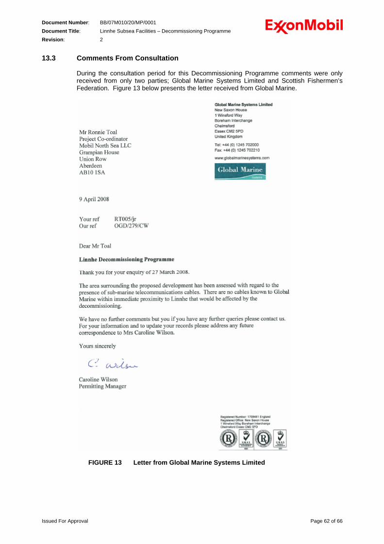
Document Number: BB/07M010/20/MP/0001 Document Title: Linnhe Subsea Facilities – Decommissioning Programme Revision: 2 13.3 Comments From Consultation
During the consultation period for this Decommissioning Programme comments were only received from only two parties; Global Marine Systems Limited and Scottish Fishermen’s Federation. Figure 13 below presents the letter received from Global Marine.
FIGURE 13 Letter from Global Marine Systems Limited
Issued For Approval Page 62 of 66
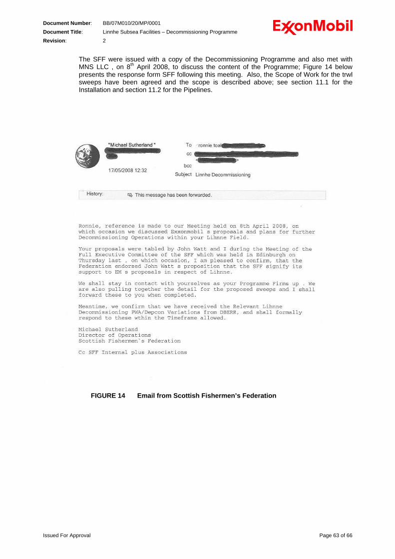
Document Number: BB/07M010/20/MP/0001 Document Title: Linnhe Subsea Facilities – Decommissioning Programme Revision: 2
The SFF were issued with a copy of the Decommissioning Programme and also met with MNS LLC , on 8th April 2008, to discuss the content of the Programme; Figure 14 below presents the response form SFF following this meeting. Also, the Scope of Work for the trwl sweeps have been agreed and the scope is described above; see section 11.1 for the Installation and section 11.2 for the Pipelines.
FIGURE 14 Email from Scottish Fishermen’s Federation
Issued For Approval Page 63 of 66
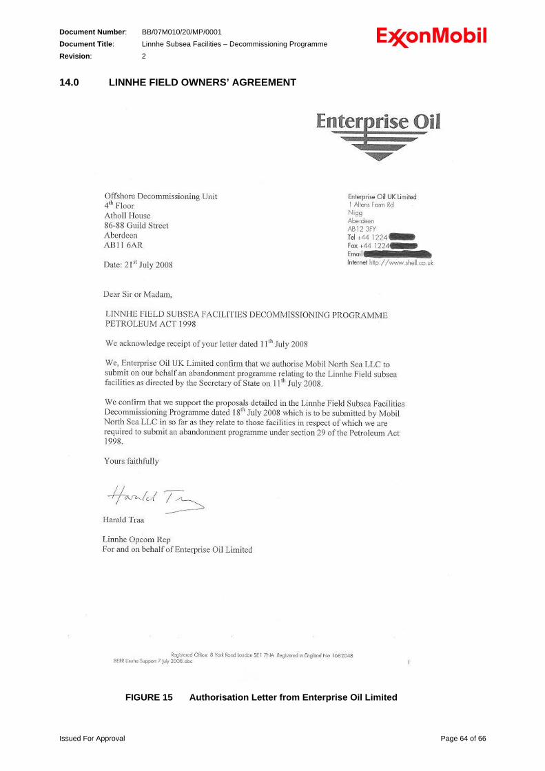
Document Number: BB/07M010/20/MP/0001 Document Title: Linnhe Subsea Facilities – Decommissioning Programme Revision: 2 14.0 LINNHE FIELD OWNERS’ AGREEMENT
FIGURE 15 Authorisation Letter from Enterprise Oil Limited
Issued For Approval Page 64 of 66
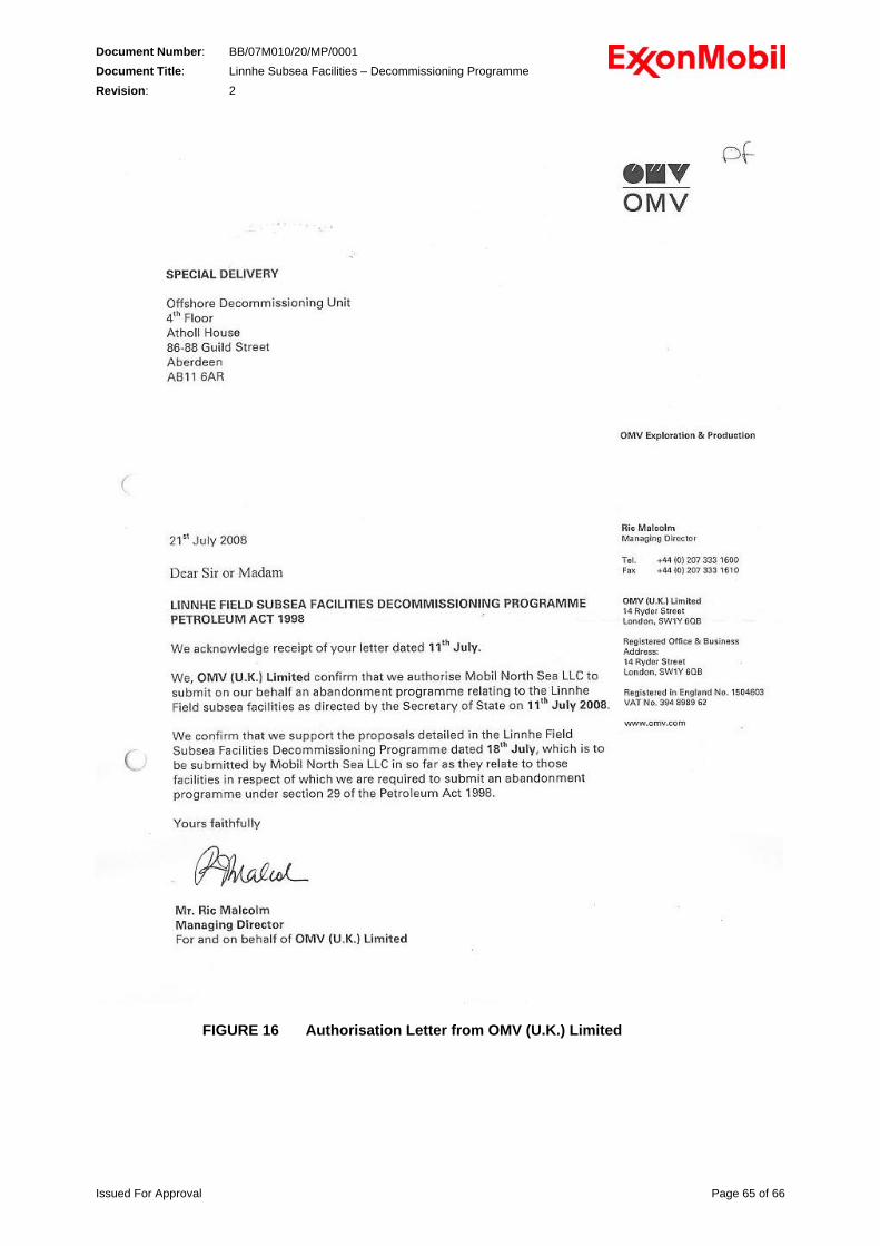
Document Number: BB/07M010/20/MP/0001 Document Title: Linnhe Subsea Facilities – Decommissioning Programme Revision: 2
FIGURE 16 Authorisation Letter from OMV (U.K.) Limited
Issued For Approval Page 65 of 66
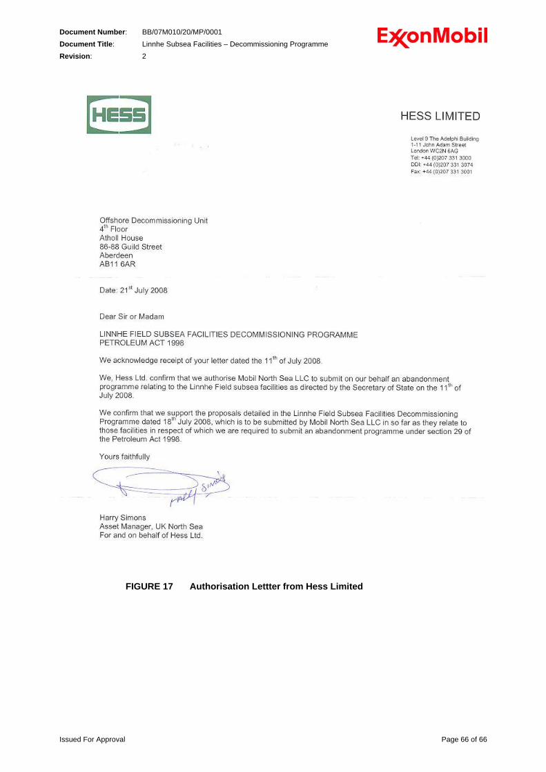
Document Number: BB/07M010/20/MP/0001 Document Title: Linnhe Subsea Facilities – Decommissioning Programme Revision: 2
FIGURE 17 Authorisation Lettter from Hess Limited
Issued For Approval Page 66 of 66