Embed Size (px)
Citation preview
LIP-ME201™ L-IP™ BACnet Router
User Manual
LOYTEC electronics GmbH
Contact
LOYTEC electronics GmbH Blumengasse 35
1170 Vienna AUSTRIA/EUROPE [email protected]
http://www.loytec.com
Version 4.8
Document № 88073505
LOYTEC MAKES AND YOU RECEIVE NO WARRANTIES OR CONDITIONS, EXPRESS, IMPLIED, STATUTORY OR IN ANY COMMUNICATION WITH YOU,
AND LOYTEC SPECIFICALLY DISCLAIMS ANY IMPLIED WARRANTY OF
MERCHANTABILITY OR FITNESS FOR A PARTICULAR PURPOSE. THIS PRODUCT IS NOT DESIGNED OR INTENDED FOR USE IN EQUIPMENT
INTENDED FOR SURGICAL IMPLANT INTO THE BODY OR OTHER APPLICATIONS INTENDED TO SUPPORT OR SUSTAIN LIFE, FOR USE IN
FLIGHT CONTROL OR ENGINE CONTROL EQUIPMENT WITHIN AN AIRCRAFT, OR FOR ANY OTHER APPLICATION IN WHICH IN THE FAILURE OF SUCH PRODUCT COULD CREATE A SITUATION IN WHICH PERSONAL
INJURY OR DEATH MAY OCCUR.
No part of this publication may be reproduced, stored in a retrieval system, or transmitted, in any form or by any means, electronic, mechanical, photocopying, recording, or
otherwise, without the prior written permission of LOYTEC.
LC3020™, L-Chip™, L-Core™, L-DALI™, L-GATE™, L-INX™, L-IOB™, LIOB-Connect™, LIOB-FT™, L-IP™, LPA™, L-Proxy™, L-Switch™, L-Term™,
L-VIS™, L-WEB™, L-ZIBI™, ORION™ stack and Smart Auto-Connect™ are trademarks of LOYTEC electronics GmbH.
LonTalk®, LONWORKS®, Neuron®, LONMARK®, LonMaker®, i.LON®, and LNS® are trademarks of Echelon Corporation registered in the United States and other countries.
LIP-ME201 User Manual 3 LOYTEC
Version 4.8 LOYTEC electronics GmbH
Contents
1 Introduction ..................................................................................................7 1.1 Overview ..............................................................................................................7 1.2 Scope.....................................................................................................................7
2 Quick-Start Guide ........................................................................................8 2.1 Hardware Installation and IP Connection........................................................8 2.2 Configuration of the LIP-ME201 ......................................................................8 2.3 MS/TP Protocol Analyzer...................................................................................8 2.4 Reset to Factory Defaults ...................................................................................9
3 Hardware Installation................................................................................10 3.1 Enclosure ...........................................................................................................10 3.2 Product Label ....................................................................................................10 3.3 Mounting............................................................................................................11 3.4 LED signals........................................................................................................11
3.4.1 Power LED ..............................................................................................11 3.4.2 Status LED...............................................................................................11 3.4.3 MSTP Activity LED ................................................................................11 3.4.4 Ethernet Link LED...................................................................................11 3.4.5 Ethernet Activity LED .............................................................................11 3.4.6 BACnet/IP LED.......................................................................................12 3.4.7 BBMD LED.............................................................................................12
3.5 Status Button .....................................................................................................12 3.6 DIP Switch Settings...........................................................................................12 3.7 Terminal Layout and Power Supply ...............................................................12 3.8 Wiring ................................................................................................................13
4 Web Interface .............................................................................................14 4.1 Device Information and Account Management .............................................14 4.2 Device Configuration ........................................................................................16
4.2.1 System Configuration ..............................................................................16 4.2.2 Backup and Restore .................................................................................17 4.2.3 Port Configuration ...................................................................................18 4.2.4 IP Configuration ......................................................................................18 4.2.5 BACnet Device Configuration.................................................................20 4.2.6 BACnet/IP Configuration ........................................................................20 4.2.7 MS/TP Configuration ..............................................................................21 4.2.8 BACnet BDT (Broadcast Distribution Table) .........................................22
LIP-ME201 User Manual 4 LOYTEC
Version 4.8 LOYTEC electronics GmbH
4.2.9 BACnet ACL (Access Control List)........................................................ 23 4.3 Device Statistics ................................................................................................ 24
4.3.1 System Log.............................................................................................. 24 4.3.2 IP Statistics .............................................................................................. 25 4.3.3 BACnet MS/TP Statistics ........................................................................ 25 4.3.4 BACnet FDT Statistics ............................................................................ 27
4.4 Reset, Contact, Logout ..................................................................................... 28 5 Operating Interfaces ..................................................................................29
5.1 BACnet Interface.............................................................................................. 29 5.1.1 Device Object.......................................................................................... 29 5.1.2 Device Name and ID ............................................................................... 30 5.1.3 Device Information ................................................................................. 30 5.1.4 Object Database....................................................................................... 31 5.1.5 Protocol Parameters................................................................................. 31 5.1.6 Diagnostics .............................................................................................. 32 5.1.7 Date & Time............................................................................................ 33 5.1.8 Time Master ............................................................................................ 33 5.1.9 Backup & Restore ................................................................................... 34 5.1.10 Slave Proxy ............................................................................................. 34
6 Network Media ...........................................................................................36 6.1 MS/TP................................................................................................................ 36
7 Firmware Update .......................................................................................37 7.1 Firmware Update via FTP ............................................................................... 37 7.2 Firmware Update via the Console................................................................... 37
8 Troubleshooting..........................................................................................39 8.1 Technical Support ............................................................................................ 39 8.2 Statistics on the Console................................................................................... 39
8.2.1 Connecting to the Console ...................................................................... 39 8.2.2 Reset configuration (load factory defaults) ............................................. 40 8.2.3 Device Statistics Menu............................................................................ 40 8.2.4 IP statistics............................................................................................... 40 8.2.5 BBMD Communications Test ................................................................. 42
8.3 MS/TP Remote Packet Capture ...................................................................... 42 8.3.1 Configure Remote Packet Capture .......................................................... 42 8.3.2 Enable Offline Capture............................................................................ 42 8.3.3 Run Wireshark Remote Capture.............................................................. 43
9 Security Hardening Guide.........................................................................47 9.1 Installation Instructions ................................................................................... 47 9.2 Firmware ........................................................................................................... 47

LIP-ME201 User Manual 5 LOYTEC
Version 4.8 LOYTEC electronics GmbH
9.3 Ports ...................................................................................................................47 9.4 Services...............................................................................................................48 9.5 Logging and Auditing .......................................................................................48
10 Specifications ..............................................................................................49 10.1 LIP-ME201 ........................................................................................................49
10.1.1 Physical Specifications ............................................................................49
11 Revision History .........................................................................................50
LIP-ME201 User Manual 6 LOYTEC
Version 4.8 LOYTEC electronics GmbH
Abbreviations
100BaseT............................ 100 Mbps Ethernet network with RJ-45 plug ACL.................................... Access Control List BACnet............................... Building Automation and Control Network BBMD ................................ BACnet Broadcast Management Device BDT.................................... Broadcast Distribution Table B/IP..................................... BACnet over IP (this is a BACnet data link layer) DHCP ................................. Dynamic Host Configuration Protocol DNS.................................... Domain Name System DST .................................... Daylight Saving Time FD....................................... Foreign Device FTP ..................................... File Transfer Protocol GMT ................................... Greenwich Mean Time IP ........................................ Internet Protocol MAC................................... Media Access Control MS/TP ................................ Master/Slave Token Passing (this is a BACnet data link layer) NAT.................................... Network Address Translation, see Internet RFC 1631 NTP .................................... Network Time Protocol
LIP-ME201 User Manual 7 LOYTEC
Version 4.8 LOYTEC electronics GmbH
1 Introduction
1.1 Overview The LIP-ME201 is a BTL-certified BACnet router between MS/TP and B/IP (BACnet over IP) as well as a BBMD (BACnet Broadcast Management Device) for transportation of BACnet broadcasts over an IP network with several subnets. Additionally, it can serve as a BACnet time master and a BACnet MS/TP slave proxy. The LIP-ME201 also provides additional features such as optional write protection of the BDT, a BACnet/IP access control list and a simple BBMD communications test to troubleshoot the network. The MS/TP port supports remote Wireshark packet capture for troubleshooting the MS/TP channel.
1.2 Scope This document covers LIP-ME201 devices.
LIP-ME201 User Manual 8 LOYTEC
Version 4.8 LOYTEC electronics GmbH
2 Quick-Start Guide
This chapter provides the minimum list of steps necessary to setup the LIP-ME201.
2.1 Hardware Installation and IP Connection
• Connect power, Ethernet, and MS/TP (Sections 3.7 and 3.8).
• Connect the Console (Section 8.2.1) and configure the IP address, netmask, and gateway or connect to the LIP-ME201 over the Web interface right away (Section 4.1) and setup the IP configuration there (Section 4.2.4).
• In both cases, reboot the LIP-ME201 to commit the new IP settings (use corresponding menu item either in console menu or Web interface).
Important! The default IP address 192.168.1.254 is only set for configuration access. It must be changed in order to make the device functional.
2.2 Configuration of the LIP-ME201
• Connect to the LIP-ME201 using the new IP address in a Web browser.
• Click on Config and enter the default administrator password 'loytec4u'. Note, that older firmware versions used 'admin' as the password.
• Click on BACnet Config and setup the BACnet Device Configuration (Section 4.2.5)
• Click on Port Config and setup the BACnet/IP and BACnet MS/TP port configuration (Sections 4.2.6, 4.2.7).
• If the LIP-ME201 should also act as a BBMD, click on BACnet BDT and setup the Broadcast Distribution Table (Section 4.2.8).
• Reboot the LIP-ME201 to commit the changes (Section 4.4).
2.3 MS/TP Protocol Analyzer The LIP-ME201 is equipped with a built-in MS/TP protocol capture facility. This facility can be used for offline logging, which stores a log file on the device, or online remote logging with Wireshark. With remote capture a Wireshark protocol analyzer on the PC can
LIP-ME201 User Manual 9 LOYTEC
Version 4.8 LOYTEC electronics GmbH
capture a live log of the MS/TP channel. For doing so, the remote capture has to be enabled. See Section 8.3 for more details.
2.4 Reset to Factory Defaults In case the password of the device has been forgotten you may need to reset the device back to factory defaults to gain access again. On the LIP-ME201 press the service button and power-cycle the device. Keep the button pressed until the port LEDs illuminate orange permanently. Release the button within five seconds from that time on to reset the device to factory defaults.
LIP-ME201 User Manual 10 LOYTEC
Version 4.8 LOYTEC electronics GmbH
3 Hardware Installation
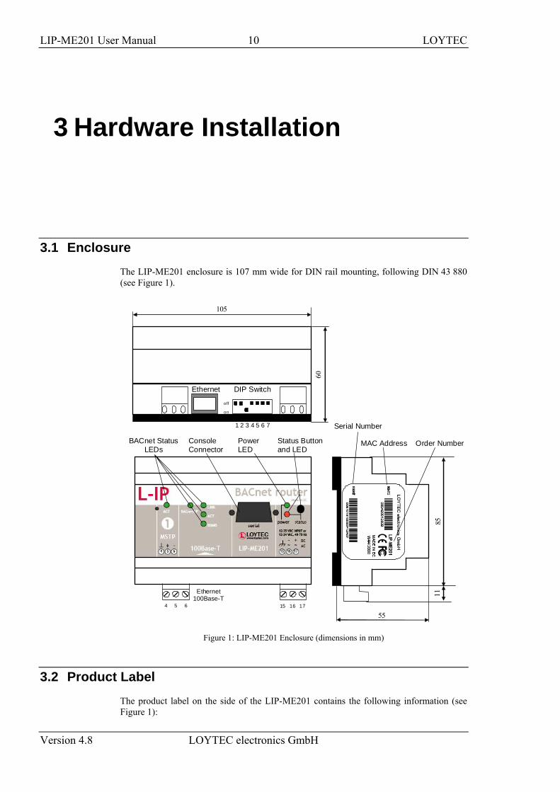
3.1 Enclosure The LIP-ME201 enclosure is 107 mm wide for DIN rail mounting, following DIN 43 880 (see Figure 1).
4 5 6
Status Buttonand LED
105
off
on
1 2 3 4 5 6 7
DIP Switch
60
55
Serial Number
Order Number85
Console Connector
Power LED
BACnet Status LEDs
Ethernet 100Base-T
Ethernet
MAC Address 11
15 16 17
Figure 1: LIP-ME201 Enclosure (dimensions in mm)
3.2 Product Label The product label on the side of the LIP-ME201 contains the following information (see Figure 1):
LIP-ME201 User Manual 11 LOYTEC
Version 4.8 LOYTEC electronics GmbH
• LIP-ME201 Order Number,
• Serial Number with bar-code (SER#),
• Ethernet MAC Address with bar-code (MAC1).
Unless stated otherwise, all bar codes are encoded using “Code 128”. An additional label is also supplied with the LIP-ME201 for documentation purposes.
3.3 Mounting The device comes prepared for mounting on DIN rails following DIN 50 022. The device can be mounted in any position. However, an installation place with proper airflow must be selected to ensure that the LIP-ME201’s temperature does not exceed the specified range (see Chapter 10).
3.4 LED signals
3.4.1 Power LED The LIP-ME201 power LED lights up green when power is supplied to terminals 16 and 17.
3.4.2 Status LED The LIP-ME201 is equipped with a red status LED (see Figure 1). This LED is normally off.
If the fall-back image is executed, the status LED flashes red once every second.
3.4.3 MSTP Activity LED The MS/TP port has a three-color MSTP Activity LED (see Figure 1). Table 1 shows the different LED patterns of the port and their meaning. A permanent color reflects a state. Flicker is for 25 ms when there is activity on the MS/TP data link layer.
Behavior Description Comment
GREEN permanently, flicker off
Multi-Master, token ok, flicker when traffic Normal condition on a multi-master MS/TP network.
ORANGE flicker Sole master, flicker when traffic Normal condition on a single-master MS/TP network.
RED permanent, flicker GREEN
Token lost state, flicker when transmit attempt Cable might be broken.
RED flash fast Transmission or receive errors This indicates bad cabling.
Table 1: MS/TP Activity LED Patterns
3.4.4 Ethernet Link LED The Ethernet Link LED lights up green whenever an Ethernet cable is plugged-in and a physical connection with a switch, hub, or PC can be established.
3.4.5 Ethernet Activity LED The Ethernet Activity LED lights up green for 6 ms whenever a packet is transmitted or received or when a collision is detected on the network cable.
LIP-ME201 User Manual 12 LOYTEC
Version 4.8 LOYTEC electronics GmbH
3.4.6 BACnet/IP LED The BACnet/IP LED flashes green for 25 ms when BACnet packets are transmitted or received over the BACnet/IP interface.
3.4.7 BBMD LED The BBMD LED is permanent green if BBMD is enabled. Otherwise, it is off.
3.5 Status Button The LIP-ME201 is equipped with a status button (see Figure 1). When pressing the status button shortly during normal operation of the LIP-ME201, it sends a BACnet “I-Am” message on all active BACnet data link layers.
The status button can also be used to switch the device back to factory default state. Press the service button and power-cycle the device. Keep the button pressed until the port LEDs illuminate orange permanently. Release the button within five seconds from that time on to reset the device to factory defaults. Alternatively, the device can be switched back to factory defaults over the console user interface (see Section 8.2.2).
3.6 DIP Switch Settings The DIP switch assignment for the LIP-ME201 is shown in Table 2. Please leave all switches at default state.
DIP Switch # Function Factory Default
1 Must be OFF OFF
2 Must be OFF OFF
3 Must be ON ON
4 Must be OFF OFF
5 Must be OFF OFF
6 Must be OFF OFF
7 Must be OFF OFF
Table 2: DIP Switch Settings for LIP-ME201
3.7 Terminal Layout and Power Supply The LIP-ME201 provides screw terminals to connect to the network as well as to the power supply. The screw terminals can be used for wires of a maximum thickness of 1.5 mm2/AWG12. The device can either be DC or AC powered.
LIP-ME201 User Manual 13 LOYTEC
Version 4.8 LOYTEC electronics GmbH
Terminal Function
4 BACnet MS/TP Ground
5 BACnet MS/TP Non-Inverting Input
6 BACnet MS/TP Inverting Input
8 Ethernet 100BaseT
15 Earth Ground
16, 17 Power Supply 12-35 VDC or 12-24 VAC ± 10% Do not connect terminal 17 to earth ground!
Table 3: LIP-ME201 Terminals
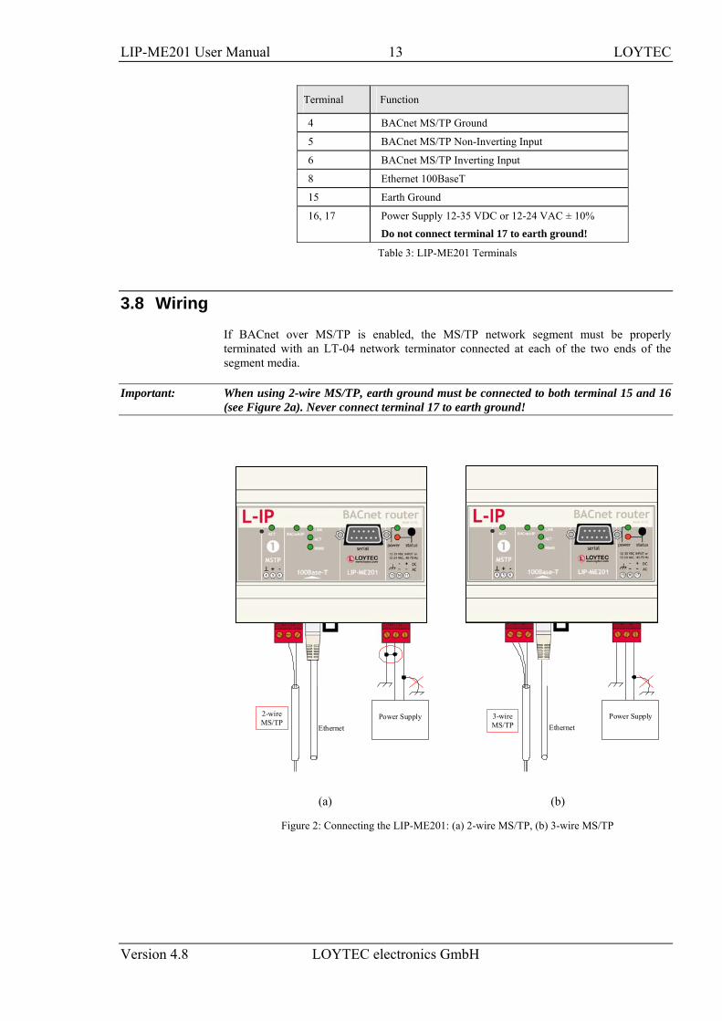
3.8 Wiring If BACnet over MS/TP is enabled, the MS/TP network segment must be properly terminated with an LT-04 network terminator connected at each of the two ends of the segment media.
Important: When using 2-wire MS/TP, earth ground must be connected to both terminal 15 and 16 (see Figure 2a). Never connect terminal 17 to earth ground!
2-wire MS/TP
Power Supply
Ethernet
Ethernet Power Supply 3-wire
MS/TP
(a) (b)
Figure 2: Connecting the LIP-ME201: (a) 2-wire MS/TP, (b) 3-wire MS/TP
LIP-ME201 User Manual 14 LOYTEC
Version 4.8 LOYTEC electronics GmbH
4 Web Interface
The LIP-ME201 comes with a built-in Web server and a Web interface to configure the LIP-ME201 and extract statistics information. The Web interface allows configuring the IP settings, BACnet and other configuration settings.
4.1 Device Information and Account Management In a Web browser, enter the default IP address 192.168.1.254 of the LIP-ME201. Note that if your PC has an IP address in a subnet other than 192.168.1.xxx, you must open a command tool and enter the following route command to add a route to device.
To Add a Route to the Device
1. Windows START Run
2. Enter ‘cmd’ and click OK.
3. In the command window enter the command line route add 192.168.1.254 %COMPUTERNAME%
In Windows7 replace %COMPUTERNAME% with the PC’s actual IP address.
4. Then open your Web browser and type in the default IP address ‘192.168.1.254’.
5. The device information page should appear as shown in Figure 3.
LIP-ME201 User Manual 15 LOYTEC
Version 4.8 LOYTEC electronics GmbH
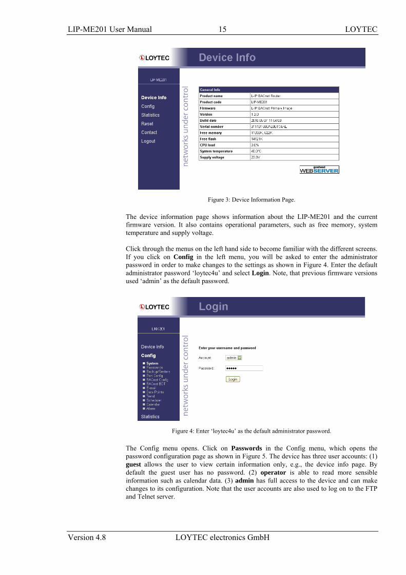
Figure 3: Device Information Page.
The device information page shows information about the LIP-ME201 and the current firmware version. It also contains operational parameters, such as free memory, system temperature and supply voltage.
Click through the menus on the left hand side to become familiar with the different screens. If you click on Config in the left menu, you will be asked to enter the administrator password in order to make changes to the settings as shown in Figure 4. Enter the default administrator password ‘loytec4u’ and select Login. Note, that previous firmware versions used ‘admin’ as the default password.
Figure 4: Enter ‘loytec4u’ as the default administrator password.
The Config menu opens. Click on Passwords in the Config menu, which opens the password configuration page as shown in Figure 5. The device has three user accounts: (1) guest allows the user to view certain information only, e.g., the device info page. By default the guest user has no password. (2) operator is able to read more sensible information such as calendar data. (3) admin has full access to the device and can make changes to its configuration. Note that the user accounts are also used to log on to the FTP and Telnet server.
LIP-ME201 User Manual 16 LOYTEC
Version 4.8 LOYTEC electronics GmbH
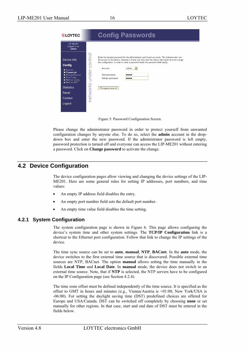
Figure 5: Password Configuration Screen.
Please change the administrator password in order to protect yourself from unwanted configuration changes by anyone else. To do so, select the admin account in the drop-down box and enter the new password. If the administrator password is left empty, password protection is turned off and everyone can access the LIP-ME201 without entering a password. Click on Change password to activate the change.
4.2 Device Configuration The device configuration pages allow viewing and changing the device settings of the LIP-ME201. Here are some general rules for setting IP addresses, port numbers, and time values:
• An empty IP address field disables the entry.
• An empty port number field sets the default port number.
• An empty time value field disables the time setting.
4.2.1 System Configuration The system configuration page is shown in Figure 6. This page allows configuring the device’s system time and other system settings. The TCP/IP Configuration link is a shortcut to the Ethernet port configuration. Follow that link to change the IP settings of the device.
The time sync source can be set to auto, manual, NTP, BACnet. In the auto mode, the device switches to the first external time source that is discovered. Possible external time sources are NTP, BACnet. The option manual allows setting the time manually in the fields Local Time and Local Date. In manual mode, the device does not switch to an external time source. Note, that if NTP is selected, the NTP servers have to be configured on the IP Configuration page (see Section 4.2.4).
The time zone offset must be defined independently of the time source. It is specified as the offset to GMT in hours and minutes (e.g., Vienna/Austria is +01:00, New York/USA is -06:00). For setting the daylight saving time (DST) predefined choices are offered for Europe and USA/Canada. DST can be switched off completely by choosing none or set manually for other regions. In that case, start and end date of DST must be entered in the fields below.
LIP-ME201 User Manual 17 LOYTEC
Version 4.8 LOYTEC electronics GmbH
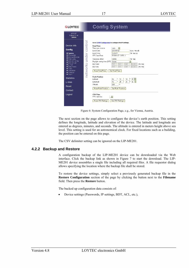
Figure 6: System Configuration Page, e.g., for Vienna, Austria.
The next section on the page allows to configure the device’s earth position. This setting defines the longitude, latitude and elevation of the device. The latitude and longitude are entered as degrees, minutes, and seconds. The altitude is entered in meters height above sea level. This setting is used for an astronomical clock. For fixed locations such as a building, the position can be entered on this page.
The CSV delimiter setting can be ignored on the LIP-ME201.
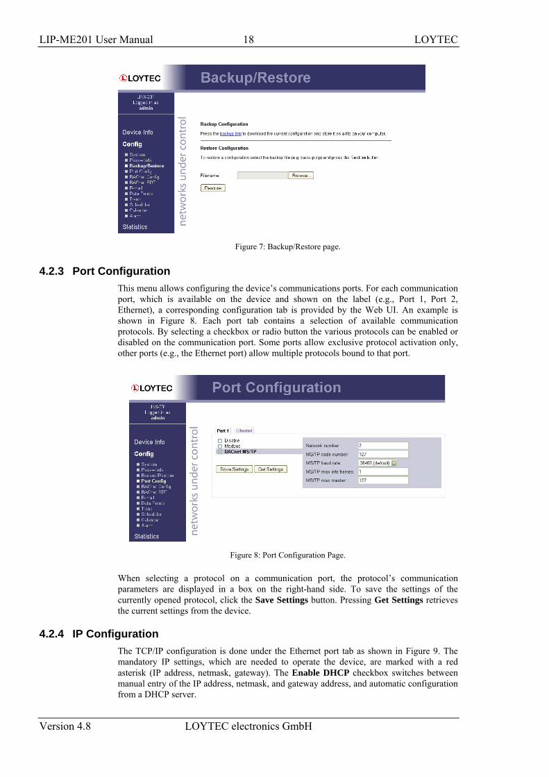
4.2.2 Backup and Restore A configuration backup of the LIP-ME201 device can be downloaded via the Web interface. Click the backup link as shown in Figure 7 to start the download. The LIP-ME201 device assembles a single file including all required files. A file requestor dialog allows specifying the location where the backup file shall be stored.
To restore the device settings, simply select a previously generated backup file in the Restore Configuration section of the page by clicking the button next to the Filename field. Then press the Restore button.
The backed up configuration data consists of:
• Device settings (Passwords, IP settings, BDT, ACL, etc.),
LIP-ME201 User Manual 18 LOYTEC
Version 4.8 LOYTEC electronics GmbH
Figure 7: Backup/Restore page.
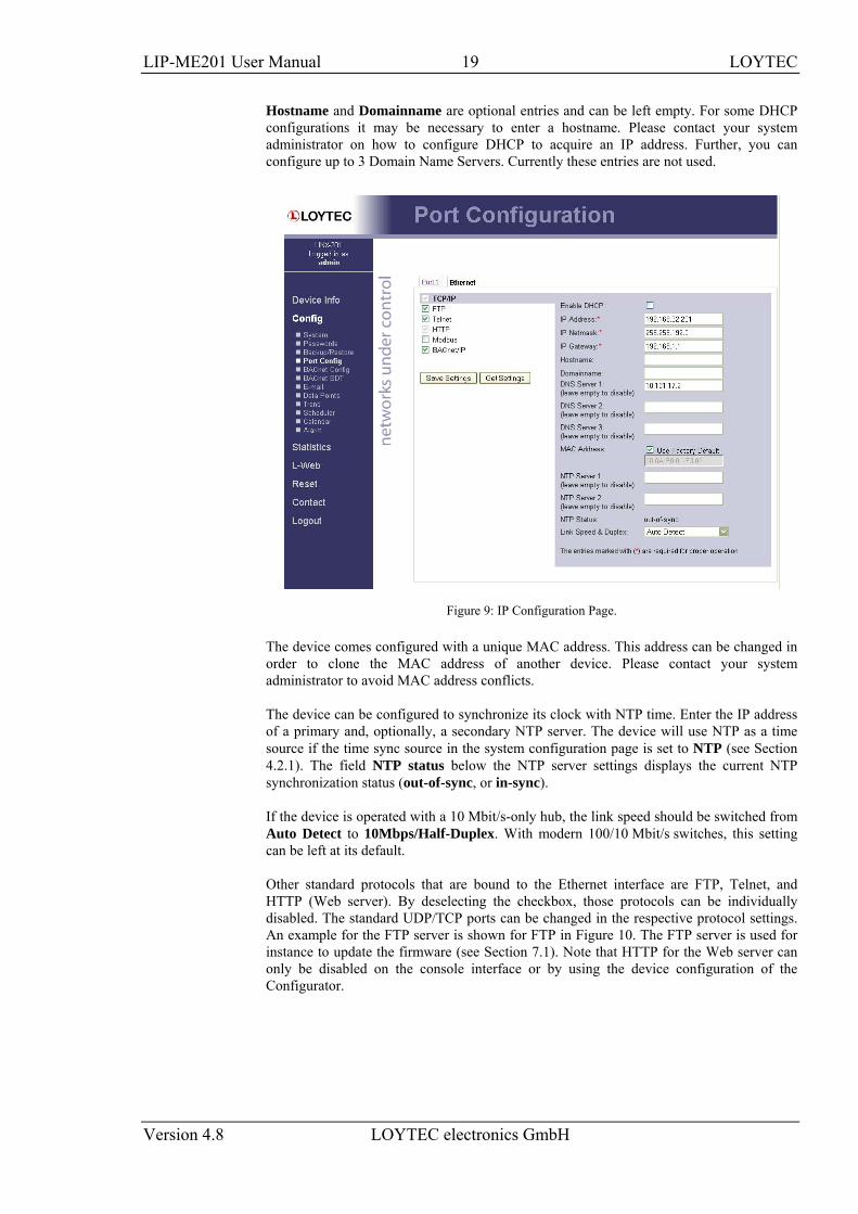
4.2.3 Port Configuration This menu allows configuring the device’s communications ports. For each communication port, which is available on the device and shown on the label (e.g., Port 1, Port 2, Ethernet), a corresponding configuration tab is provided by the Web UI. An example is shown in Figure 8. Each port tab contains a selection of available communication protocols. By selecting a checkbox or radio button the various protocols can be enabled or disabled on the communication port. Some ports allow exclusive protocol activation only, other ports (e.g., the Ethernet port) allow multiple protocols bound to that port.
Figure 8: Port Configuration Page.
When selecting a protocol on a communication port, the protocol’s communication parameters are displayed in a box on the right-hand side. To save the settings of the currently opened protocol, click the Save Settings button. Pressing Get Settings retrieves the current settings from the device.
4.2.4 IP Configuration The TCP/IP configuration is done under the Ethernet port tab as shown in Figure 9. The mandatory IP settings, which are needed to operate the device, are marked with a red asterisk (IP address, netmask, gateway). The Enable DHCP checkbox switches between manual entry of the IP address, netmask, and gateway address, and automatic configuration from a DHCP server.
LIP-ME201 User Manual 19 LOYTEC
Version 4.8 LOYTEC electronics GmbH
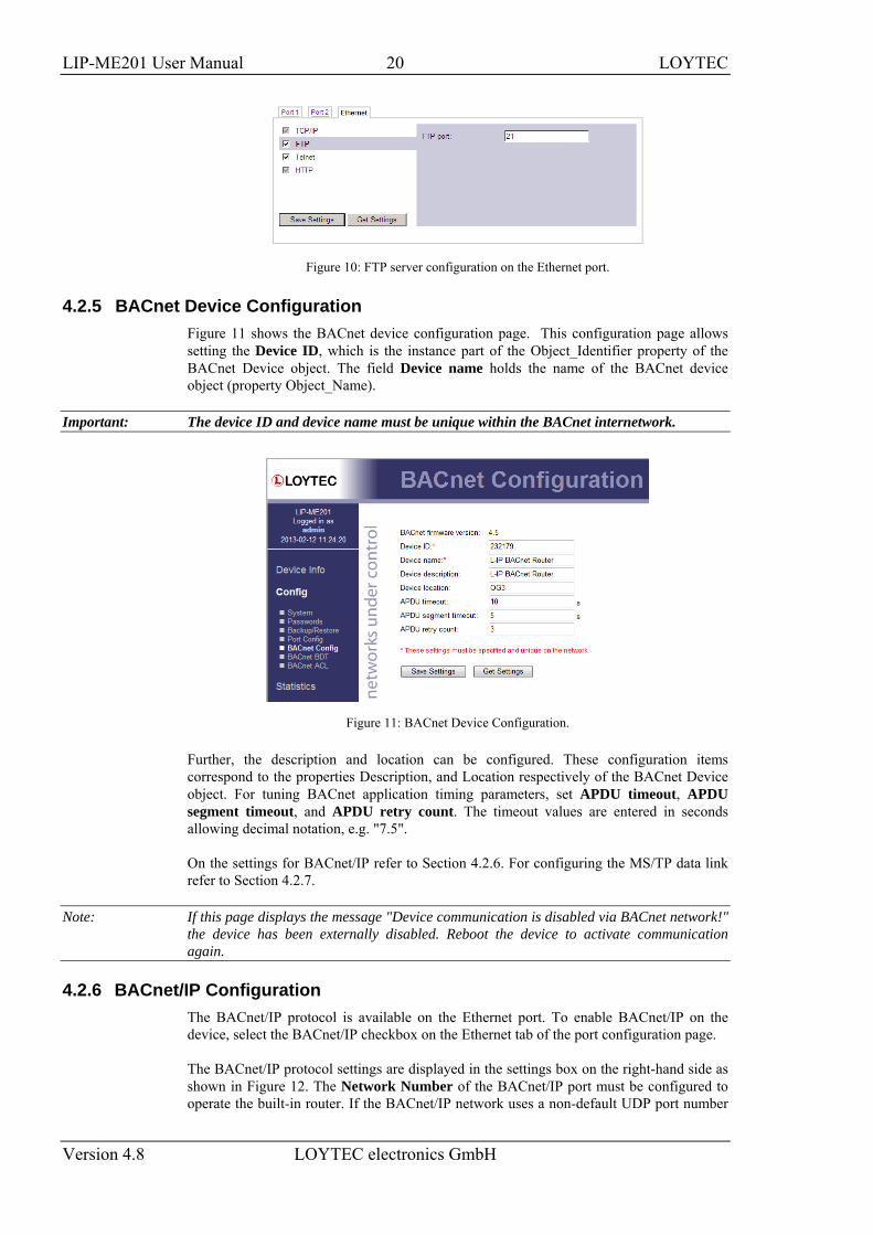
Hostname and Domainname are optional entries and can be left empty. For some DHCP configurations it may be necessary to enter a hostname. Please contact your system administrator on how to configure DHCP to acquire an IP address. Further, you can configure up to 3 Domain Name Servers. Currently these entries are not used.
Figure 9: IP Configuration Page.
The device comes configured with a unique MAC address. This address can be changed in order to clone the MAC address of another device. Please contact your system administrator to avoid MAC address conflicts.
The device can be configured to synchronize its clock with NTP time. Enter the IP address of a primary and, optionally, a secondary NTP server. The device will use NTP as a time source if the time sync source in the system configuration page is set to NTP (see Section 4.2.1). The field NTP status below the NTP server settings displays the current NTP synchronization status (out-of-sync, or in-sync).
If the device is operated with a 10 Mbit/s-only hub, the link speed should be switched from Auto Detect to 10Mbps/Half-Duplex. With modern 100/10 Mbit/s switches, this setting can be left at its default.
Other standard protocols that are bound to the Ethernet interface are FTP, Telnet, and HTTP (Web server). By deselecting the checkbox, those protocols can be individually disabled. The standard UDP/TCP ports can be changed in the respective protocol settings. An example for the FTP server is shown for FTP in Figure 10. The FTP server is used for instance to update the firmware (see Section 7.1). Note that HTTP for the Web server can only be disabled on the console interface or by using the device configuration of the Configurator.
LIP-ME201 User Manual 20 LOYTEC
Version 4.8 LOYTEC electronics GmbH
Figure 10: FTP server configuration on the Ethernet port.
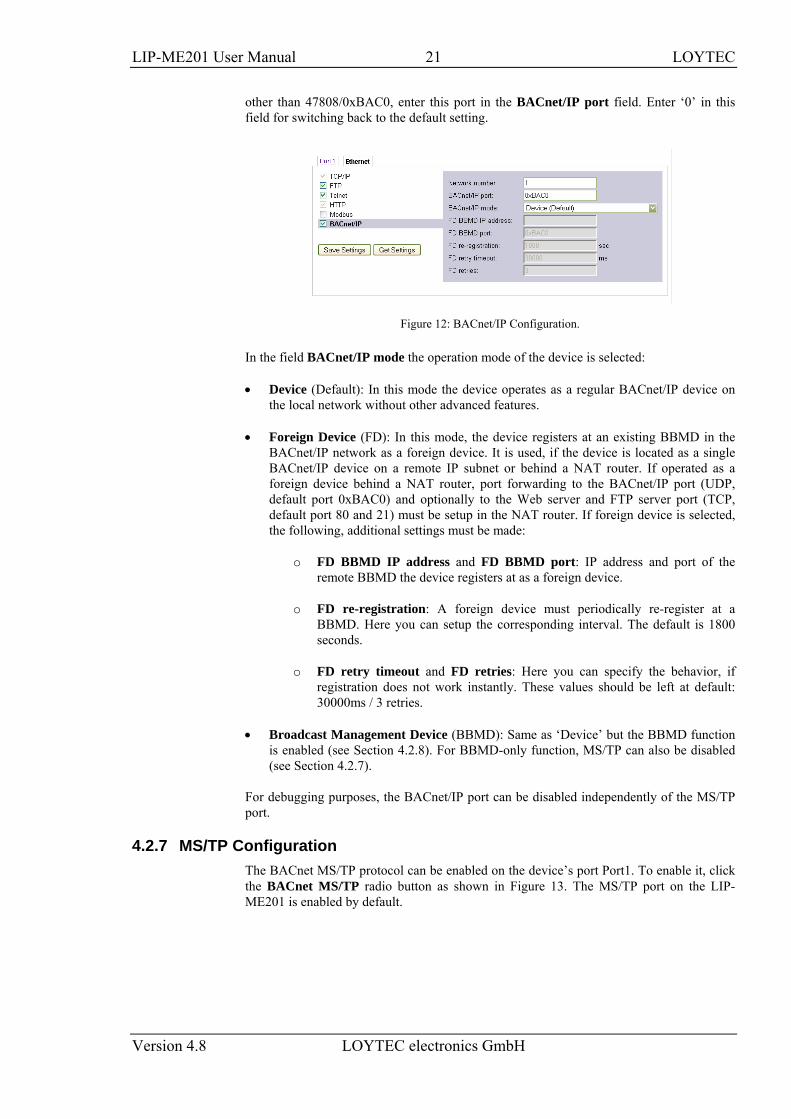
4.2.5 BACnet Device Configuration Figure 11 shows the BACnet device configuration page. This configuration page allows setting the Device ID, which is the instance part of the Object_Identifier property of the BACnet Device object. The field Device name holds the name of the BACnet device object (property Object_Name).
Important: The device ID and device name must be unique within the BACnet internetwork.
Figure 11: BACnet Device Configuration.
Further, the description and location can be configured. These configuration items correspond to the properties Description, and Location respectively of the BACnet Device object. For tuning BACnet application timing parameters, set APDU timeout, APDU segment timeout, and APDU retry count. The timeout values are entered in seconds allowing decimal notation, e.g. "7.5".
On the settings for BACnet/IP refer to Section 4.2.6. For configuring the MS/TP data link refer to Section 4.2.7.
Note: If this page displays the message "Device communication is disabled via BACnet network!" the device has been externally disabled. Reboot the device to activate communication again.
4.2.6 BACnet/IP Configuration The BACnet/IP protocol is available on the Ethernet port. To enable BACnet/IP on the device, select the BACnet/IP checkbox on the Ethernet tab of the port configuration page.
The BACnet/IP protocol settings are displayed in the settings box on the right-hand side as shown in Figure 12. The Network Number of the BACnet/IP port must be configured to operate the built-in router. If the BACnet/IP network uses a non-default UDP port number
LIP-ME201 User Manual 21 LOYTEC
Version 4.8 LOYTEC electronics GmbH
other than 47808/0xBAC0, enter this port in the BACnet/IP port field. Enter ‘0’ in this field for switching back to the default setting.
Figure 12: BACnet/IP Configuration.
In the field BACnet/IP mode the operation mode of the device is selected:
• Device (Default): In this mode the device operates as a regular BACnet/IP device on the local network without other advanced features.
• Foreign Device (FD): In this mode, the device registers at an existing BBMD in the BACnet/IP network as a foreign device. It is used, if the device is located as a single BACnet/IP device on a remote IP subnet or behind a NAT router. If operated as a foreign device behind a NAT router, port forwarding to the BACnet/IP port (UDP, default port 0xBAC0) and optionally to the Web server and FTP server port (TCP, default port 80 and 21) must be setup in the NAT router. If foreign device is selected, the following, additional settings must be made:
o FD BBMD IP address and FD BBMD port: IP address and port of the remote BBMD the device registers at as a foreign device.
o FD re-registration: A foreign device must periodically re-register at a BBMD. Here you can setup the corresponding interval. The default is 1800 seconds.
o FD retry timeout and FD retries: Here you can specify the behavior, if registration does not work instantly. These values should be left at default: 30000ms / 3 retries.
• Broadcast Management Device (BBMD): Same as ‘Device’ but the BBMD function is enabled (see Section 4.2.8). For BBMD-only function, MS/TP can also be disabled (see Section 4.2.7).
For debugging purposes, the BACnet/IP port can be disabled independently of the MS/TP port.
4.2.7 MS/TP Configuration The BACnet MS/TP protocol can be enabled on the device’s port Port1. To enable it, click the BACnet MS/TP radio button as shown in Figure 13. The MS/TP port on the LIP-ME201 is enabled by default.
LIP-ME201 User Manual 22 LOYTEC
Version 4.8 LOYTEC electronics GmbH
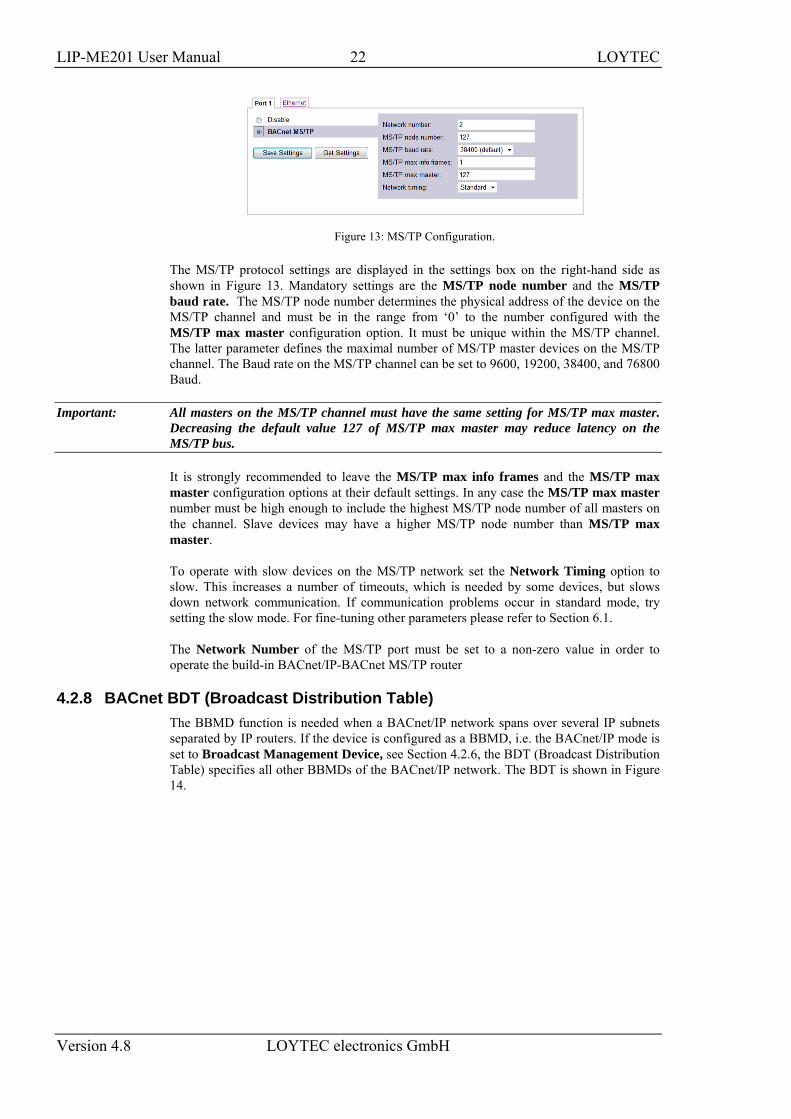
Figure 13: MS/TP Configuration.
The MS/TP protocol settings are displayed in the settings box on the right-hand side as shown in Figure 13. Mandatory settings are the MS/TP node number and the MS/TP baud rate. The MS/TP node number determines the physical address of the device on the MS/TP channel and must be in the range from ‘0’ to the number configured with the MS/TP max master configuration option. It must be unique within the MS/TP channel. The latter parameter defines the maximal number of MS/TP master devices on the MS/TP channel. The Baud rate on the MS/TP channel can be set to 9600, 19200, 38400, and 76800 Baud.
Important: All masters on the MS/TP channel must have the same setting for MS/TP max master. Decreasing the default value 127 of MS/TP max master may reduce latency on the MS/TP bus.
It is strongly recommended to leave the MS/TP max info frames and the MS/TP max master configuration options at their default settings. In any case the MS/TP max master number must be high enough to include the highest MS/TP node number of all masters on the channel. Slave devices may have a higher MS/TP node number than MS/TP max master.
To operate with slow devices on the MS/TP network set the Network Timing option to slow. This increases a number of timeouts, which is needed by some devices, but slows down network communication. If communication problems occur in standard mode, try setting the slow mode. For fine-tuning other parameters please refer to Section 6.1.
The Network Number of the MS/TP port must be set to a non-zero value in order to operate the build-in BACnet/IP-BACnet MS/TP router
4.2.8 BACnet BDT (Broadcast Distribution Table) The BBMD function is needed when a BACnet/IP network spans over several IP subnets separated by IP routers. If the device is configured as a BBMD, i.e. the BACnet/IP mode is set to Broadcast Management Device, see Section 4.2.6, the BDT (Broadcast Distribution Table) specifies all other BBMDs of the BACnet/IP network. The BDT is shown in Figure 14.
LIP-ME201 User Manual 23 LOYTEC
Version 4.8 LOYTEC electronics GmbH
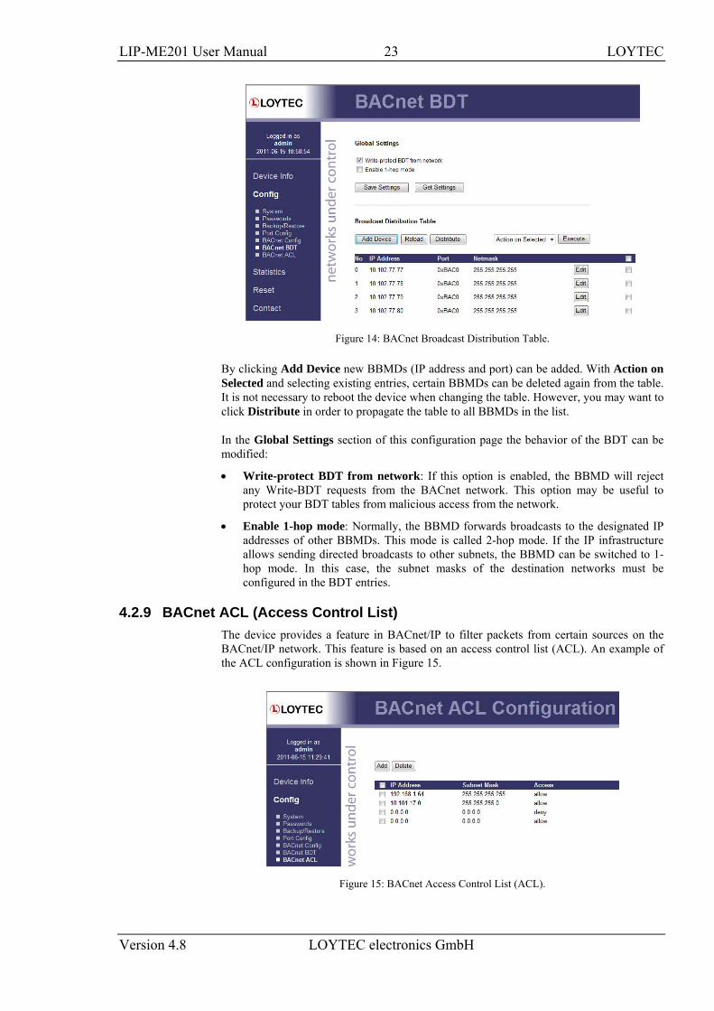
Figure 14: BACnet Broadcast Distribution Table.
By clicking Add Device new BBMDs (IP address and port) can be added. With Action on Selected and selecting existing entries, certain BBMDs can be deleted again from the table. It is not necessary to reboot the device when changing the table. However, you may want to click Distribute in order to propagate the table to all BBMDs in the list.
In the Global Settings section of this configuration page the behavior of the BDT can be modified:
• Write-protect BDT from network: If this option is enabled, the BBMD will reject any Write-BDT requests from the BACnet network. This option may be useful to protect your BDT tables from malicious access from the network.
• Enable 1-hop mode: Normally, the BBMD forwards broadcasts to the designated IP addresses of other BBMDs. This mode is called 2-hop mode. If the IP infrastructure allows sending directed broadcasts to other subnets, the BBMD can be switched to 1-hop mode. In this case, the subnet masks of the destination networks must be configured in the BDT entries.
4.2.9 BACnet ACL (Access Control List) The device provides a feature in BACnet/IP to filter packets from certain sources on the BACnet/IP network. This feature is based on an access control list (ACL). An example of the ACL configuration is shown in Figure 15.
Figure 15: BACnet Access Control List (ACL).
LIP-ME201 User Manual 24 LOYTEC
Version 4.8 LOYTEC electronics GmbH
The user can add and delete entries to the ACL. Each entry contains a source specification, which consists of an IP address and an IP mask, and an action (allow or deny). For specifying single hosts use the IP address and the mask '255.255.255.255'. For an address range specify an appropriate mask. For example use '10.101.17.0' and the mask '255.255.255.0' to specify all hosts with IP addresses '10.101.17.xxx'. To specify all IP addresses use '0.0.0.0' and the mask '0.0.0.0'.
The ACL is evaluated from specific host entries down to wider ranges. When adding new entries the ACL is automatically sorted, having the most precise definition at the top and the most general one at the bottom. The default behavior is to allow packets from all IP addresses. This is also the default entry in the ACL.
The example shown in Figure 15 specifies the following behavior for BACnet/IP:
1. Allow packets from the device 192.168.1.64
2. Otherwise allow packets from devices in the network 10.101.17.xxx
3. Otherwise deny packets from all (other) IP addresses. Note, that a rule for "deny" overrules an equal rule for "allow".
4.3 Device Statistics The device statistics pages provide the system log , statistics information about the Ethernet and the BACnet MS/TP interface, as well as a list of registered foreign devices.
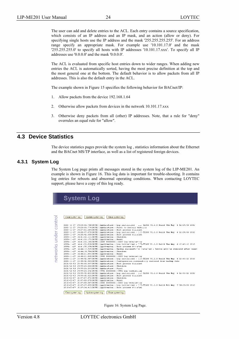
4.3.1 System Log The System Log page prints all messages stored in the system log of the LIP-ME201. An example is shown in Figure 16. This log data is important for trouble-shooting. It contains log entries for reboots and abnormal operating conditions. When contacting LOYTEC support, please have a copy of this log ready.
Figure 16: System Log Page.
LIP-ME201 User Manual 25 LOYTEC
Version 4.8 LOYTEC electronics GmbH
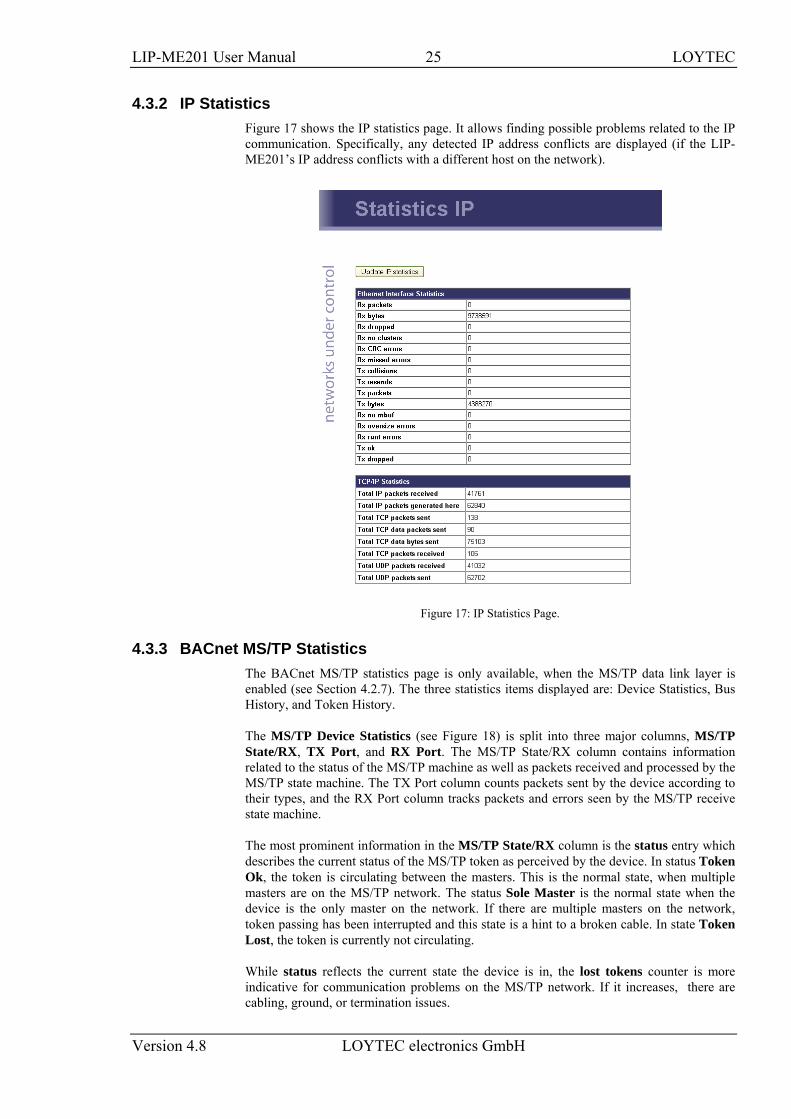
4.3.2 IP Statistics Figure 17 shows the IP statistics page. It allows finding possible problems related to the IP communication. Specifically, any detected IP address conflicts are displayed (if the LIP-ME201’s IP address conflicts with a different host on the network).
Figure 17: IP Statistics Page.
4.3.3 BACnet MS/TP Statistics The BACnet MS/TP statistics page is only available, when the MS/TP data link layer is enabled (see Section 4.2.7). The three statistics items displayed are: Device Statistics, Bus History, and Token History.
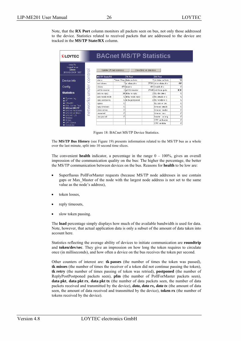
The MS/TP Device Statistics (see Figure 18) is split into three major columns, MS/TP State/RX, TX Port, and RX Port. The MS/TP State/RX column contains information related to the status of the MS/TP machine as well as packets received and processed by the MS/TP state machine. The TX Port column counts packets sent by the device according to their types, and the RX Port column tracks packets and errors seen by the MS/TP receive state machine.
The most prominent information in the MS/TP State/RX column is the status entry which describes the current status of the MS/TP token as perceived by the device. In status Token Ok, the token is circulating between the masters. This is the normal state, when multiple masters are on the MS/TP network. The status Sole Master is the normal state when the device is the only master on the network. If there are multiple masters on the network, token passing has been interrupted and this state is a hint to a broken cable. In state Token Lost, the token is currently not circulating.
While status reflects the current state the device is in, the lost tokens counter is more indicative for communication problems on the MS/TP network. If it increases, there are cabling, ground, or termination issues.
LIP-ME201 User Manual 26 LOYTEC
Version 4.8 LOYTEC electronics GmbH
Note, that the RX Port column monitors all packets seen on bus, not only those addressed to the device. Statistics related to received packets that are addressed to the device are tracked in the MS/TP State/RX column.
Figure 18: BACnet MS/TP Device Statistics.
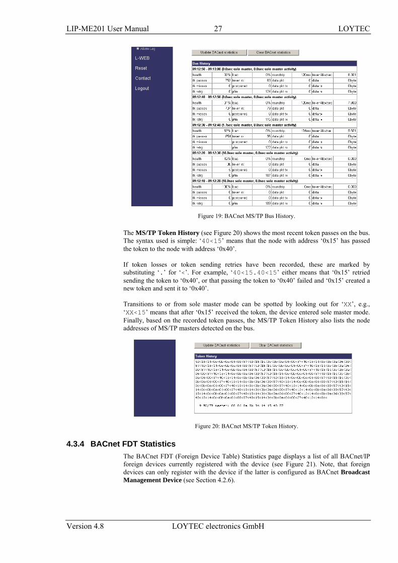
The MS/TP Bus History (see Figure 19) presents information related to the MS/TP bus as a whole over the last minute, split into 10 second time slices.
The convenient health indicator, a percentage in the range 0 – 100%, gives an overall impression of the communication quality on the bus: The higher the percentage, the better the MS/TP communication between devices on the bus. Reasons for health to be low are:
• Superfluous PollForMaster requests (because MS/TP node addresses in use contain gaps or Max_Master of the node with the largest node address is not set to the same value as the node’s address),
• token losses,
• reply timeouts,
• slow token passing.
The load percentage simply displays how much of the available bandwidth is used for data. Note, however, that actual application data is only a subset of the amount of data taken into account here.
Statistics reflecting the average ability of devices to initiate communication are roundtrip and token/dev/sec. They give an impression on how long the token requires to circulate once (in milliseconds), and how often a device on the bus receives the token per second.
Other counters of interest are: tk passes (the number of times the token was passed), tk misses (the number of times the receiver of a token did not continue passing the token), tk retry (the number of times passing of token was retried), postponed (the number of ReplyPostPostponed packets seen), pfm (the number of PollForMaster packets seen), data pkt, data pkt rx, data pkt tx (the number of data packets seen, the number of data packets received and transmitted by the device), data, data rx, data tx (the amount of data seen, the amount of data received and transmitted by the device), token rx (the number of tokens received by the device).
LIP-ME201 User Manual 27 LOYTEC
Version 4.8 LOYTEC electronics GmbH
Figure 19: BACnet MS/TP Bus History.
The MS/TP Token History (see Figure 20) shows the most recent token passes on the bus. The syntax used is simple: ‘40<15’ means that the node with address ‘0x15’ has passed the token to the node with address ‘0x40’.
If token losses or token sending retries have been recorded, these are marked by substituting ‘.’ for ‘<’. For example, ‘40<15.40<15’ either means that ‘0x15’ retried sending the token to ‘0x40’, or that passing the token to ‘0x40’ failed and ‘0x15’ created a new token and sent it to ‘0x40’.
Transitions to or from sole master mode can be spotted by looking out for ‘XX’, e.g., ‘XX<15’ means that after ‘0x15’ received the token, the device entered sole master mode. Finally, based on the recorded token passes, the MS/TP Token History also lists the node addresses of MS/TP masters detected on the bus.
Figure 20: BACnet MS/TP Token History.
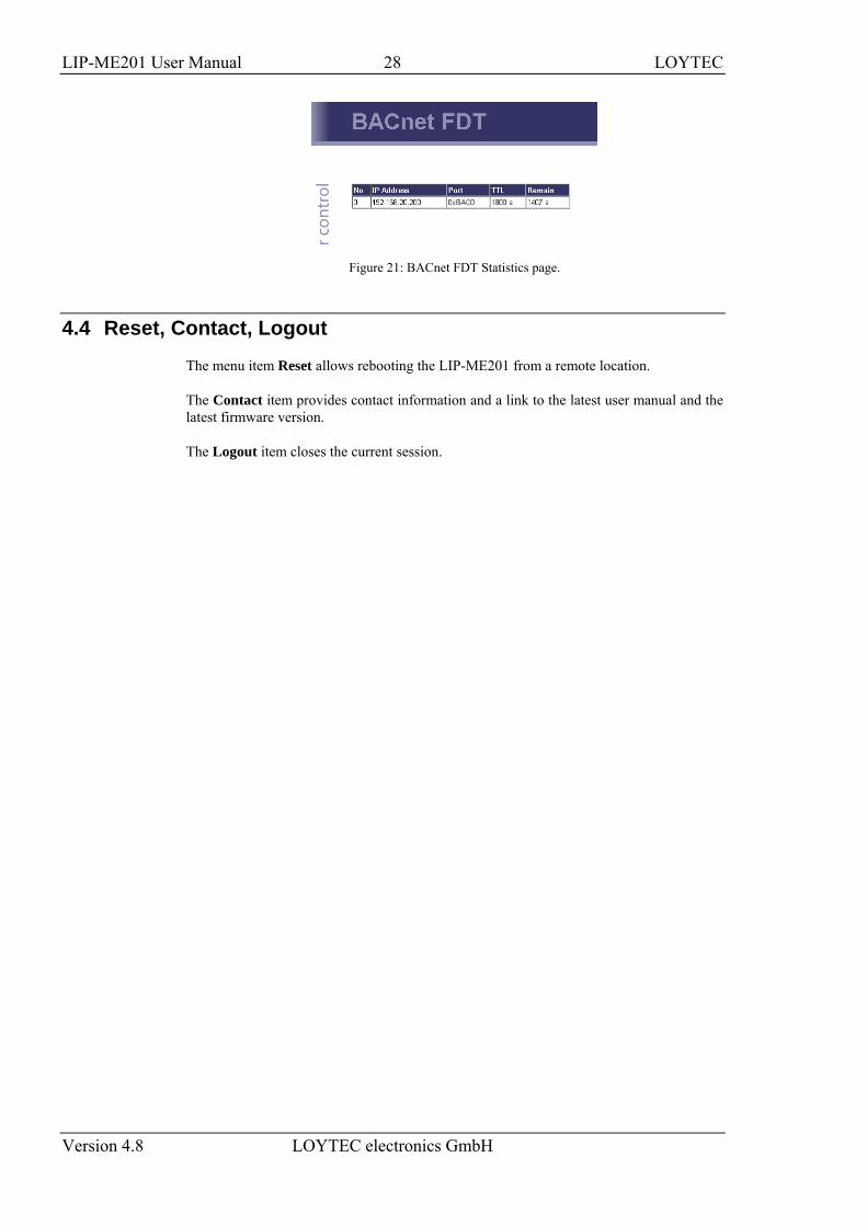
4.3.4 BACnet FDT Statistics The BACnet FDT (Foreign Device Table) Statistics page displays a list of all BACnet/IP foreign devices currently registered with the device (see Figure 21). Note, that foreign devices can only register with the device if the latter is configured as BACnet Broadcast Management Device (see Section 4.2.6).
LIP-ME201 User Manual 28 LOYTEC
Version 4.8 LOYTEC electronics GmbH
Figure 21: BACnet FDT Statistics page.
4.4 Reset, Contact, Logout
The menu item Reset allows rebooting the LIP-ME201 from a remote location.
The Contact item provides contact information and a link to the latest user manual and the latest firmware version.
The Logout item closes the current session.
LIP-ME201 User Manual 29 LOYTEC
Version 4.8 LOYTEC electronics GmbH
5 Operating Interfaces
5.1 BACnet Interface
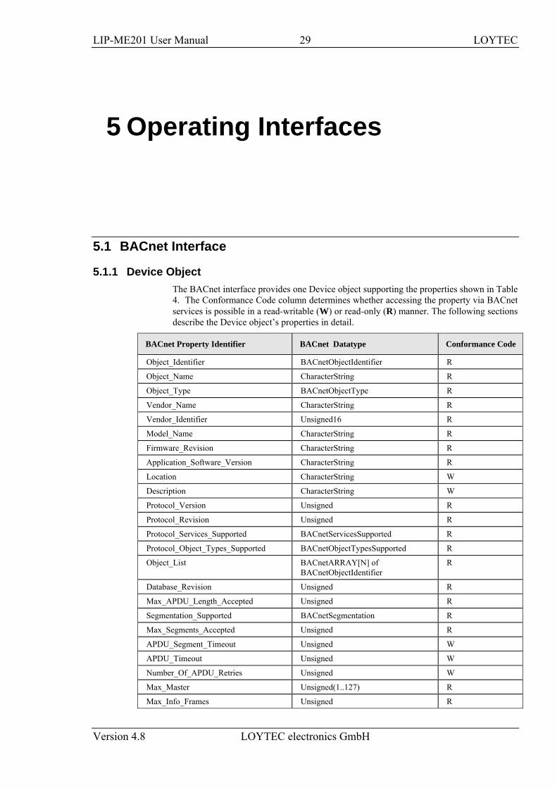
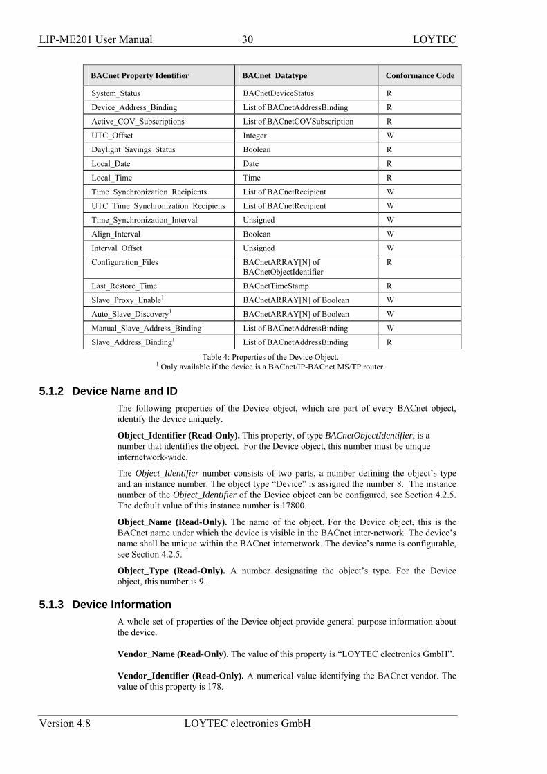
5.1.1 Device Object The BACnet interface provides one Device object supporting the properties shown in Table 4. The Conformance Code column determines whether accessing the property via BACnet services is possible in a read-writable (W) or read-only (R) manner. The following sections describe the Device object’s properties in detail.
BACnet Property Identifier BACnet Datatype Conformance Code
Object_Identifier BACnetObjectIdentifier R
Object_Name CharacterString R
Object_Type BACnetObjectType R
Vendor_Name CharacterString R
Vendor_Identifier Unsigned16 R
Model_Name CharacterString R
Firmware_Revision CharacterString R
Application_Software_Version CharacterString R
Location CharacterString W
Description CharacterString W
Protocol_Version Unsigned R
Protocol_Revision Unsigned R
Protocol_Services_Supported BACnetServicesSupported R
Protocol_Object_Types_Supported BACnetObjectTypesSupported R
Object_List BACnetARRAY[N] of BACnetObjectIdentifier
R
Database_Revision Unsigned R
Max_APDU_Length_Accepted Unsigned R
Segmentation_Supported BACnetSegmentation R
Max_Segments_Accepted Unsigned R
APDU_Segment_Timeout Unsigned W
APDU_Timeout Unsigned W
Number_Of_APDU_Retries Unsigned W
Max_Master Unsigned(1..127) R
Max_Info_Frames Unsigned R
LIP-ME201 User Manual 30 LOYTEC
Version 4.8 LOYTEC electronics GmbH
BACnet Property Identifier BACnet Datatype Conformance Code
System_Status BACnetDeviceStatus R
Device_Address_Binding List of BACnetAddressBinding R
Active_COV_Subscriptions List of BACnetCOVSubscription R
UTC_Offset Integer W
Daylight_Savings_Status Boolean R
Local_Date Date R
Local_Time Time R
Time_Synchronization_Recipients List of BACnetRecipient W
UTC_Time_Synchronization_Recipiens List of BACnetRecipient W
Time_Synchronization_Interval Unsigned W
Align_Interval Boolean W
Interval_Offset Unsigned W
Configuration_Files BACnetARRAY[N] of BACnetObjectIdentifier
R
Last_Restore_Time BACnetTimeStamp R
Slave_Proxy_Enable1 BACnetARRAY[N] of Boolean W
Auto_Slave_Discovery1 BACnetARRAY[N] of Boolean W
Manual_Slave_Address_Binding1 List of BACnetAddressBinding W
Slave_Address_Binding1 List of BACnetAddressBinding R
Table 4: Properties of the Device Object. 1 Only available if the device is a BACnet/IP-BACnet MS/TP router.
5.1.2 Device Name and ID The following properties of the Device object, which are part of every BACnet object, identify the device uniquely.
Object_Identifier (Read-Only). This property, of type BACnetObjectIdentifier, is a number that identifies the object. For the Device object, this number must be unique internetwork-wide.
The Object_Identifier number consists of two parts, a number defining the object’s type and an instance number. The object type “Device” is assigned the number 8. The instance number of the Object_Identifier of the Device object can be configured, see Section 4.2.5. The default value of this instance number is 17800.
Object_Name (Read-Only). The name of the object. For the Device object, this is the BACnet name under which the device is visible in the BACnet inter-network. The device’s name shall be unique within the BACnet internetwork. The device’s name is configurable, see Section 4.2.5.
Object_Type (Read-Only). A number designating the object’s type. For the Device object, this number is 9.
5.1.3 Device Information A whole set of properties of the Device object provide general purpose information about the device.
Vendor_Name (Read-Only). The value of this property is “LOYTEC electronics GmbH”.
Vendor_Identifier (Read-Only). A numerical value identifying the BACnet vendor. The value of this property is 178.

LIP-ME201 User Manual 31 LOYTEC
Version 4.8 LOYTEC electronics GmbH
Model_Name (Read-Only). The value of this property is equal to the product code of the device, i.e., its value is “LIP-ME201”.
Firmware_Revision (Read-Only). The value of this property gives the current firmware version of the device.
Application_Software_Version (Read-Only). The value of this property gives the build date and the version of the current firmware.
Location (Read-Writable). A string intended to be used to describe the location of the device, e.g., “1st floor”. This property can be set via the configuration UI, see Section 4.2.5. The default value is “unknown”.
Description (Read-Only). A string intended to hold a user specified description of the device. This property can be changed via the configuration UI, see Section 4.2.5.
Protocol_Version (Read-Only). The BACnet protocol version supported by the device. The value of this property is 1.
Protocol_Revision (Read-Only). The BACnet protocol revision of the BACnet version supported by the device. The value of this property is 5.
Protocol_Services_Supported (Read-Only). A string of bits marking which BACnet services can be executed by the device. For a detailed list of the BACnet services supported, please refer to the product’s PICS document.
Protocol_Object_Types_Supported (Read-Only). A string of bits identifying which BACnet object types are supported by the device. For a detailed list of supported object types, please refer to the product’s PICS document.
5.1.4 Object Database The following properties of the Device object provide information about the BACnet objects contained in the device.
Object_List (Read-Only). This property holds a sequence of object IDs (object type, object instance pairs), one object ID for each object within the device that is accessible through BACnet services.
Database_Revision (Read-Only). This property, of type Unsigned, is a logical revision number for the device's object database. It is incremented when an object is created, an object is deleted, an object's name is changed, an object's Object_Identifier property is changed, or a restore is performed.
5.1.5 Protocol Parameters BACnet protocol parameters are accessible via the Device object properties listed below.
Max_APDU_Length_Accepted (Read-Only). The maximal size of a BACnet APDU (Application Protocol Data Unit) accepted by the device. The value of this property is 487 if BACnet MS/TP is used and 1476 if BACnet/IP is used. When the device can act as a router between BACnet/IP and BACnet MS/TP, the value of this property is 1476.
Segmentation_Supported (Read-Only). The value of this property indicates whether and which kind of segmentation is supported by a device. The value of this property is SEGMENTED_BOTH.
Max_Segments_Accepted (Read-Only). The maximum numbers of segments accepted by a device. The value of this property is 16.
LIP-ME201 User Manual 32 LOYTEC
Version 4.8 LOYTEC electronics GmbH
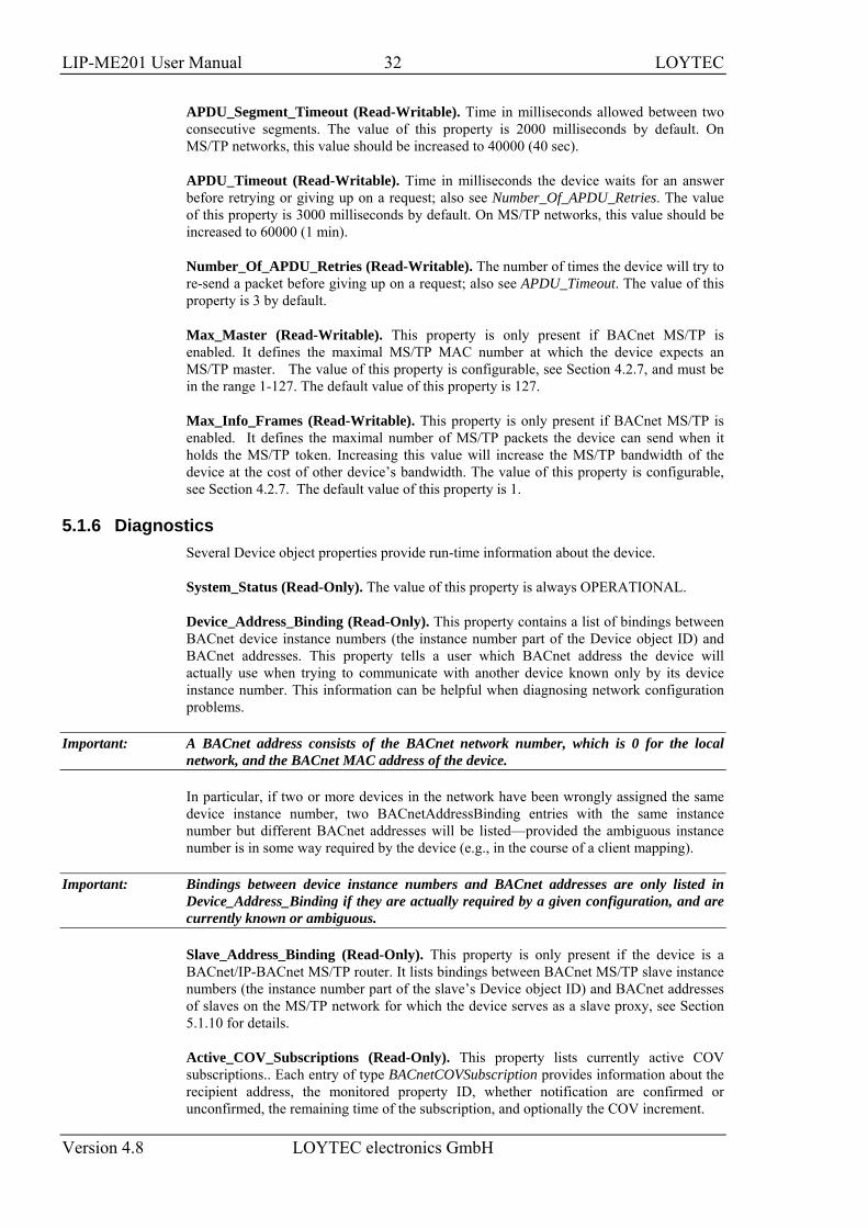
APDU_Segment_Timeout (Read-Writable). Time in milliseconds allowed between two consecutive segments. The value of this property is 2000 milliseconds by default. On MS/TP networks, this value should be increased to 40000 (40 sec).
APDU_Timeout (Read-Writable). Time in milliseconds the device waits for an answer before retrying or giving up on a request; also see Number_Of_APDU_Retries. The value of this property is 3000 milliseconds by default. On MS/TP networks, this value should be increased to 60000 (1 min).
Number_Of_APDU_Retries (Read-Writable). The number of times the device will try to re-send a packet before giving up on a request; also see APDU_Timeout. The value of this property is 3 by default.
Max_Master (Read-Writable). This property is only present if BACnet MS/TP is enabled. It defines the maximal MS/TP MAC number at which the device expects an MS/TP master. The value of this property is configurable, see Section 4.2.7, and must be in the range 1-127. The default value of this property is 127.
Max_Info_Frames (Read-Writable). This property is only present if BACnet MS/TP is enabled. It defines the maximal number of MS/TP packets the device can send when it holds the MS/TP token. Increasing this value will increase the MS/TP bandwidth of the device at the cost of other device’s bandwidth. The value of this property is configurable, see Section 4.2.7. The default value of this property is 1.
5.1.6 Diagnostics Several Device object properties provide run-time information about the device.
System_Status (Read-Only). The value of this property is always OPERATIONAL.
Device_Address_Binding (Read-Only). This property contains a list of bindings between BACnet device instance numbers (the instance number part of the Device object ID) and BACnet addresses. This property tells a user which BACnet address the device will actually use when trying to communicate with another device known only by its device instance number. This information can be helpful when diagnosing network configuration problems.
Important: A BACnet address consists of the BACnet network number, which is 0 for the local network, and the BACnet MAC address of the device.
In particular, if two or more devices in the network have been wrongly assigned the same device instance number, two BACnetAddressBinding entries with the same instance number but different BACnet addresses will be listed—provided the ambiguous instance number is in some way required by the device (e.g., in the course of a client mapping).
Important: Bindings between device instance numbers and BACnet addresses are only listed in Device_Address_Binding if they are actually required by a given configuration, and are currently known or ambiguous.
Slave_Address_Binding (Read-Only). This property is only present if the device is a BACnet/IP-BACnet MS/TP router. It lists bindings between BACnet MS/TP slave instance numbers (the instance number part of the slave’s Device object ID) and BACnet addresses of slaves on the MS/TP network for which the device serves as a slave proxy, see Section 5.1.10 for details.
Active_COV_Subscriptions (Read-Only). This property lists currently active COV subscriptions.. Each entry of type BACnetCOVSubscription provides information about the recipient address, the monitored property ID, whether notification are confirmed or unconfirmed, the remaining time of the subscription, and optionally the COV increment.
LIP-ME201 User Manual 33 LOYTEC
Version 4.8 LOYTEC electronics GmbH
Whenever the device receives a valid COV subscription via one of the BACnet services SubscribeCOV or SubscribeCOVProperty, a new entry is added to the list or an existing entry is updated (re-subscription). An entry is removed from Active_COV_Subscriptions when a subscription terminates, either because it times out or because it is actively unsubscribed by the subscriber.
5.1.7 Date & Time The device’s time and date are exposed to the network via the following set of Device object properties.
UTC_Offset (Read-Writable). This Integer value specifies the time difference between local time and UTC in minutes, effectively determining the time zone. The value of this property is configurable, see Section 4.2.1.
Important! Note that UTC_Offset is relative to local time and not relative to UTC, i.e., a time zone offset of GMT+1 (Berlin, Paris, Vienna) corresponds to UTC_Offset being set to -60 (minutes).
Daylight_Savings_Status (Read-Only). This Boolean value indicates whether (TRUE) or not (FALSE) daylight saving correction of the local time is currently active. The daylight saving scheme is configurable, see Section 4.2.1.
Local_Date (Read-Only). The current date according to the device’s clock. The value of this property can be changed via the configuration UI, see Section 4.2.1.
Local_Time (Read-Only). The current time according to the device’s clock. The value of this property can be changed via the configuration UI, see Section 4.2.1.
5.1.8 Time Master The device can serve as a BACnet time master, i.e., it can issue TimeSynchronization and UTCTimeSynchronization request on time synchronization events. A time synchronization event occurs after rebooting, when the device’s clock changes, and, if so configured, periodically. The following properties of the Device objct are used to configure the time master.
Time_Synchronization_Recipients (Read-Writable). This list of recipients will receive TimeSynchronization requests on time synchronization events. A recipients is either specified by its device ID (the object ID of its Device object), or its BACnet address.
UTC_Time_Synchronization_Recipients (Read-Writable). This list of recipients will receive UTCTimeSynchronization requests on time synchronization events. A recipients is either specified by its device ID (the object ID of its Device object), or its BACnet address.
Time_Synchronization_Interval (Read-Writable). The Unsigned value of this property specified the time interval in minutes in which periodic time synchronization events are created. If set to zero, no periodic time synchronization events are generated.
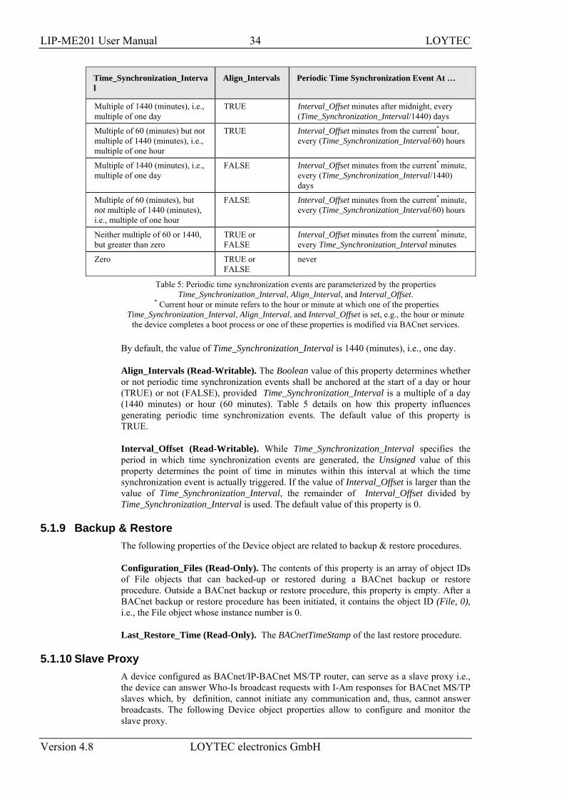
The actual clock time at which periodic time synchronization events are generated is determined by the properties Time_Synchronization_Interval, Align_Interval, and Interval_Offset; Table 5 outlines how these properties interact.
LIP-ME201 User Manual 34 LOYTEC
Version 4.8 LOYTEC electronics GmbH
Time_Synchronization_Interval
Align_Intervals Periodic Time Synchronization Event At …
Multiple of 1440 (minutes), i.e., multiple of one day
TRUE Interval_Offset minutes after midnight, every (Time_Synchronization_Interval/1440) days
Multiple of 60 (minutes) but not multiple of 1440 (minutes), i.e., multiple of one hour
TRUE Interval_Offset minutes from the current* hour, every (Time_Synchronization_Interval/60) hours
Multiple of 1440 (minutes), i.e., multiple of one day
FALSE Interval_Offset minutes from the current* minute, every (Time_Synchronization_Interval/1440) days
Multiple of 60 (minutes), but not multiple of 1440 (minutes), i.e., multiple of one hour
FALSE Interval_Offset minutes from the current* minute, every (Time_Synchronization_Interval/60) hours
Neither multiple of 60 or 1440, but greater than zero
TRUE or FALSE
Interval_Offset minutes from the current* minute, every Time_Synchronization_Interval minutes
Zero TRUE or FALSE
never
Table 5: Periodic time synchronization events are parameterized by the properties Time_Synchronization_Interval, Align_Interval, and Interval_Offset.
* Current hour or minute refers to the hour or minute at which one of the properties Time_Synchronization_Interval, Align_Interval, and Interval_Offset is set, e.g., the hour or minute
the device completes a boot process or one of these properties is modified via BACnet services.
By default, the value of Time_Synchronization_Interval is 1440 (minutes), i.e., one day.
Align_Intervals (Read-Writable). The Boolean value of this property determines whether or not periodic time synchronization events shall be anchored at the start of a day or hour (TRUE) or not (FALSE), provided Time_Synchronization_Interval is a multiple of a day (1440 minutes) or hour (60 minutes). Table 5 details on how this property influences generating periodic time synchronization events. The default value of this property is TRUE.
Interval_Offset (Read-Writable). While Time_Synchronization_Interval specifies the period in which time synchronization events are generated, the Unsigned value of this property determines the point of time in minutes within this interval at which the time synchronization event is actually triggered. If the value of Interval_Offset is larger than the value of Time_Synchronization_Interval, the remainder of Interval_Offset divided by Time_Synchronization_Interval is used. The default value of this property is 0.
5.1.9 Backup & Restore The following properties of the Device object are related to backup & restore procedures.
Configuration_Files (Read-Only). The contents of this property is an array of object IDs of File objects that can backed-up or restored during a BACnet backup or restore procedure. Outside a BACnet backup or restore procedure, this property is empty. After a BACnet backup or restore procedure has been initiated, it contains the object ID (File, 0), i.e., the File object whose instance number is 0.
Last_Restore_Time (Read-Only). The BACnetTimeStamp of the last restore procedure.
5.1.10 Slave Proxy A device configured as BACnet/IP-BACnet MS/TP router, can serve as a slave proxy i.e., the device can answer Who-Is broadcast requests with I-Am responses for BACnet MS/TP slaves which, by definition, cannot initiate any communication and, thus, cannot answer broadcasts. The following Device object properties allow to configure and monitor the slave proxy.
LIP-ME201 User Manual 35 LOYTEC
Version 4.8 LOYTEC electronics GmbH
Slave_Proxy_Enable (Read-Writable). For each BACnet MS/TP port, this property contains a Boolean that allows a user to enable (TRUE) or disable (FALSE) the slave proxy for the given port. By default, the slave proxy is enabled on all MS/TP ports.
Auto_Slave_Discovery (Read-Writable). For each BACnet MS/TP port, the slave proxy is capable of auto-detecting slaves on the MS/TP network attached to the port. This auto-detection mechanism can be disabled (FALSE) or enabled (TRUE) by changing the Boolean values stored in this property. Aside from auto-detecting slaves, the presence of slaves can also be manually configured using the property Manual_Slave_Address_Binding. By default, slave auto-detection is enabled on all MS/TP ports.
Note: Due to bandwidth and latency limitations on MS/TP networks, the auto-discovery process may initially take up to 10min. However, once, slaves have been discovered, slaves will be quickly re-discovered after reboots or power-outs since the slave proxy caches information about slaves found on the MS/TP networks. To speed up auto-detection of slaves newly added to an existing MS/TP network for which auto-detection is enabled, simply disable and then re-enable auto-detection on given MS/TP port, i.e., set Auto_Slave_Discovery for the port to FALSE and then back to TRUE.
Manual_Slave_Address_Binding (Read-Writable). Aside from auto-detecting slaves, see Auto_Slave_Discovery, slave bindings can also be manually configured via this property. Each entry of this list is a BACnetAddressBinding, i.e., a pair consisting of a slave device’s instance number and its BACnet address. Note, that bindings in this list may not necessarily appear in the property Slave_Address_Binding, e.g., if for a given binding no physical slave is present at the respecive MS/TP MAC address.
Important: Only use Manual_Slave_Address_Binding if the slave is not auto-detected. Note, that bindings in Manual_Slave_Address_Binding must contain the correct network number of the MS/TP network to which the slave is attached.
Slave_Address_Binding (Read-Only). This property lists bindings of instance numbers and BACnet addresses of all slaves for which the slave proxy answers Who-Is requests. Thus, this property can be used to check if slaves have been auto-discovered or manually bound successfully. The property is also helpful in discovering network configuration issues involving slaves: If two or more slaves on the attached MS/TP networks have been erroneously assigned the same device instance number (the instance number of the slave’s Device object), the given instance number will be listed accordingly often in this property.
LIP-ME201 User Manual 36 LOYTEC
Version 4.8 LOYTEC electronics GmbH
6 Network Media
6.1 MS/TP MS/TP is an RS-485 protocol and usually needs three wires (negative, positive, and reference). Polarity must be connected correctly. When using 2-wire MS/TP, earth ground must be connected to the negative terminal of the power supply. Never connect the positive terminal of the power supply to earth ground! See Section 3.8 for wiring instructions. Each MS/TP network segment must be properly terminated. Use an LT-04 network terminator connected at each of the two ends of the segment media.
The RS-485 transceiver of the device represents a full-load on the RS-485 bus. Consequently, a minimum of 31 devices are supported on the MS/TP channel. More devices may be possible, if they represent half-load or quarter-load. Please consult the third-party documentation. If more MS/TP devices need to be connected, use an RS-485 repeater to separate them electrically.
Logically, the MS/TP bus supports up to 255 devices. Each MS/TP device must be assigned a unique MAC address. Up to 127 MS/TP masters can be connected. Make sure, that the Max_Master setting includes the highest MS/TP master MAC address.
For operation of some slower devices on the MS/TP network it is recommended to set the following properties of the device object to fine-tune communication on the network:
• APDU_Timeout = 60000 (1 min).
• APDU_Segement_Timeout = 40000 (40 sec).
• Optionally, disable MS/TP slave proxy if not needed in order to optimize bandwidth usage: Slave_Proxy_Enable = { False }.
LIP-ME201 User Manual 37 LOYTEC
Version 4.8 LOYTEC electronics GmbH
7 Firmware Update
The LIP-ME201 firmware supports remote firmware upgrade over the network and the serial console.
To guarantee that the LIP-ME201 is not destroyed due to a failed firmware update, the firmware consists of two images:
• LIP-ME201 fallback image,
• LIP-ME201 primary image.
The LIP-ME201 fallback image cannot be changed. Thus, if the update of the primary image fails or the image is destroyed by some other means, the fallback image is booted and allows reinstalling a valid primary image.
When the LIP-ME201 boots up with the fallback image, the status LED is flashing red.
7.1 Firmware Update via FTP The LIP-ME201 primary image can be updated using any FTP client. Connect to the LIP-ME201 using its IP address and the admin account (user ‘admin’, password of admin account, see Section 4.2.4). Then change to the folder ‘dev’ and overwrite the file ‘bacrtr_lc3k_primary.dl’ with the new firmware. The LIP-ME201 will automatically reboot after the file has been transferred.
7.2 Firmware Update via the Console To download the firmware via the console interface, the LIP-ME201 must be connected to the RS-232 port of a PC via its console interface as described in Section 8.2.1. You will need the LOYTEC serial upgrade tool (LSU Tool), which can be downloaded from our homepage at www.loytec.com.
Please make sure that the LIP-ME201 console shows the main menu otherwise navigate to the main menu or simply reset the LIP-ME201.
To Upgrade via the Console
1. Double click on the *.dlc file that comes with the new firmware package. This should start the LSU Tool and load the firmware image referenced in the dlc file. Please note that the dlc file and the dl file must be stored in the same folder. The start window of the LSU tool is shown in Figure 22.
LIP-ME201 User Manual 38 LOYTEC
Version 4.8 LOYTEC electronics GmbH
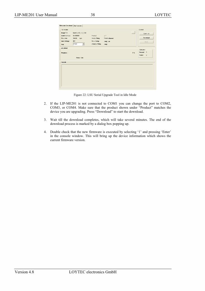
Figure 22: LSU Serial Upgrade Tool in Idle Mode
2. If the LIP-ME201 is not connected to COM1 you can change the port to COM2, COM3, or COM4. Make sure that the product shown under “Product” matches the device you are upgrading. Press “Download” to start the download.
3. Wait till the download completes, which will take several minutes. The end of the download process is marked by a dialog box popping up.
4. Double check that the new firmware is executed by selecting ‘1’ and pressing ‘Enter’ in the console window. This will bring up the device information which shows the current firmware version.
LIP-ME201 User Manual 39 LOYTEC
Version 4.8 LOYTEC electronics GmbH
8 Troubleshooting
8.1 Technical Support LOYTEC offers free telephone and e-mail support for our LIP-ME201 product. If none of the above descriptions solves your specific problem please contact us at the following address:
LOYTEC electronics GmbH Blumengasse 35 A-1170 Vienna Austria / Europe
email : [email protected] web : http://www.loytec.com tel : +43/1/40208050 fax : +43/1/402080599
or
LOYTEC Americas Inc. N27 W23957 Paul Road Suite 103 Pewaukee, WI 53072 USA
Email: [email protected] web: http://www.loytec-americas.com tel: +1 (512) 402 5319 fax: +1 (262) 408 5238
8.2 Statistics on the Console
8.2.1 Connecting to the Console Use a PC terminal program with the communication settings set to 38,400 bps / 8 data bits / no parity / 1 stop bit / no handshake. To connect COM1 of the PC to the Console on the device, use a standard null-modem cable with full handshaking. Power up the device or press Return if the device is already running. The menu shown in Figure 23 should appear on the terminal.
LIP-ME201 User Manual 40 LOYTEC
Version 4.8 LOYTEC electronics GmbH
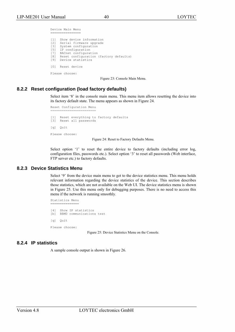
Device Main Menu ================ [1] Show device information [2] Serial firmware upgrade [3] System configuration [5] IP configuration [7] BACnet configuration [8] Reset configuration (factory defaults) [9] Device statistics [0] Reset device Please choose:
Figure 23: Console Main Menu.
8.2.2 Reset configuration (load factory defaults) Select item ‘8’ in the console main menu. This menu item allows resetting the device into its factory default state. The menu appears as shown in Figure 24. Reset Configuration Menu ======================== [1] Reset everything to factory defaults [3] Reset all passwords [q] Quit Please choose:
Figure 24: Reset to Factory Defaults Menu.
Select option ‘1’ to reset the entire device to factory defaults (including error log, configuration files, passwords etc.). Select option ‘3’ to reset all passwords (Web interface, FTP server etc.) to factory defaults.
8.2.3 Device Statistics Menu Select ‘9’ from the device main menu to get to the device statistics menu. This menu holds relevant information regarding the device statistics of the device. This section describes those statistics, which are not available on the Web UI. The device statistics menu is shown in Figure 25. Use this menu only for debugging purposes. There is no need to access this menu if the network is running smoothly. Statistics Menu =============== [4] Show IP statistics [b] BBMD communications test [q] Quit Please choose:
Figure 25: Device Statistics Menu on the Console.
8.2.4 IP statistics A sample console output is shown in Figure 26.
LIP-ME201 User Manual 41 LOYTEC
Version 4.8 LOYTEC electronics GmbH
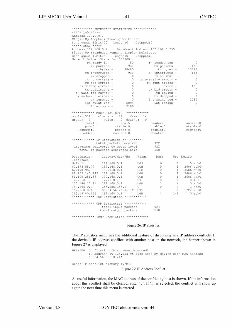
*********** INTERFACE STATISTICS ************ ***** lo0 ***** Address:127.0.0.1 Flags: Up Loopback Running Multicast Send queue limit:50 length:0 Dropped:0 ***** eth0 ***** Address:192.168.0.2 Broadcast Address:192.168.0.255 Flags: Up Broadcast Running Simplex Multicast Send queue limit:50 length:0 Dropped:0 Network Driver Stats for CS8900 : rx ready len - 50 rx loaded len - 0 rx packets - 931 tx packets - 165 rx bytes - 78480 tx bytes - 13627 rx interrupts - 931 tx interrupts - 165 rx dropped - 0 rx no mbuf - 0 rx no custers - 0 rx oversize errors - 0 rx crc errors - 0 rx runt errors - 0 rx missed errors - 0 tx ok - 165 tx collisions - 0 tx bid errors - 0 tx wait for rdy4tx - 0 tx rdy4tx - 0 tx underrun errors - 0 tx dropped - 2 tx resends - 0 int swint req - 2094 int swint res - 2094 int lockup - 0 interrupts - 3189 ************ MBUF STATISTICS ************ mbufs: 512 clusters: 64 free: 14 drops: 0 waits: 0 drains: 0 free:461 data:51 header:0 socket:0 pcb:0 rtable:0 htable:0 atable:0 soname:0 soopts:0 ftable:0 rights:0 ifaddr:0 control:0 oobdata:0 ************ IP Statistics ************ total packets received 922 datagrams delivered to upper level 922 total ip packets generated here 158 Destination Gateway/Mask/Hw Flags Refs Use Expire Interface default 192.168.0.1 UGS 6 0 0 eth0 62.178.55.77 192.168.0.1 UGH 0 1 3606 eth0 62.178.95.96 192.168.0.1 UGH 0 1 3606 eth0 81.109.145.243 192.168.0.1 UGH 0 1 3606 eth0 81.109.251.36 192.168.0.1 UGH 0 1 3606 eth0 127.0.0.1 127.0.0.1 UH 0 0 0 lo0 130.140.10.21 192.168.0.1 UGH 1 6 0 eth0 192.168.0.0 255.255.255.0 U 0 0 3 eth0 192.168.0.1 00:04:5A:26:96:1F UHL 7 0 1722 eth0 213.18.80.166 192.168.0.1 UGH 1 148 0 eth0 ************ TCP Statistics ************ ************ UDP Statistics ************ total input packets 924 total output packets 158 ************ ICMP Statistics ************
Figure 26: IP Statistics.
The IP statistics menu has the additional feature of displaying any IP address conflicts. If the device’s IP address conflicts with another host on the network, the banner shown in Figure 27 is displayed. WARNING: Conflicting IP address detected! IP address 10.125.123.95 also used by device with MAC address 00 04 5A CC 10 41! Clear IP conflict history (y/n):
Figure 27: IP Address Conflict.
As useful information, the MAC address of the conflicting host is shown. If the information about this conflict shall be cleared, enter ‘y’. If ‘n’ is selected, the conflict will show up again the next time this menu is entered.
LIP-ME201 User Manual 42 LOYTEC
Version 4.8 LOYTEC electronics GmbH
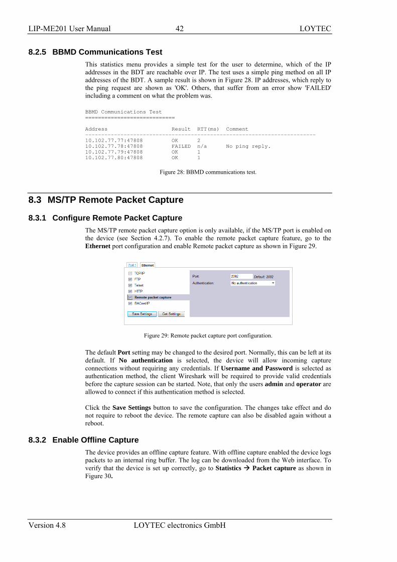
8.2.5 BBMD Communications Test This statistics menu provides a simple test for the user to determine, which of the IP addresses in the BDT are reachable over IP. The test uses a simple ping method on all IP addresses of the BDT. A sample result is shown in Figure 28. IP addresses, which reply to the ping request are shown as 'OK'. Others, that suffer from an error show 'FAILED' including a comment on what the problem was. BBMD Communications Test ============================ Address Result RTT(ms) Comment ------------------------------------------------------------------------ 10.102.77.77:47808 OK 2 10.102.77.78:47808 FAILED n/a No ping reply. 10.102.77.79:47808 OK 1 10.102.77.80:47808 OK 1
Figure 28: BBMD communications test.
8.3 MS/TP Remote Packet Capture
8.3.1 Configure Remote Packet Capture The MS/TP remote packet capture option is only available, if the MS/TP port is enabled on the device (see Section 4.2.7). To enable the remote packet capture feature, go to the Ethernet port configuration and enable Remote packet capture as shown in Figure 29.
Figure 29: Remote packet capture port configuration.
The default Port setting may be changed to the desired port. Normally, this can be left at its default. If No authentication is selected, the device will allow incoming capture connections without requiring any credentials. If Username and Password is selected as authentication method, the client Wireshark will be required to provide valid credentials before the capture session can be started. Note, that only the users admin and operator are allowed to connect if this authentication method is selected.
Click the Save Settings button to save the configuration. The changes take effect and do not require to reboot the device. The remote capture can also be disabled again without a reboot.
8.3.2 Enable Offline Capture The device provides an offline capture feature. With offline capture enabled the device logs packets to an internal ring buffer. The log can be downloaded from the Web interface. To verify that the device is set up correctly, go to Statistics Packet capture as shown in Figure 30.
LIP-ME201 User Manual 43 LOYTEC
Version 4.8 LOYTEC electronics GmbH
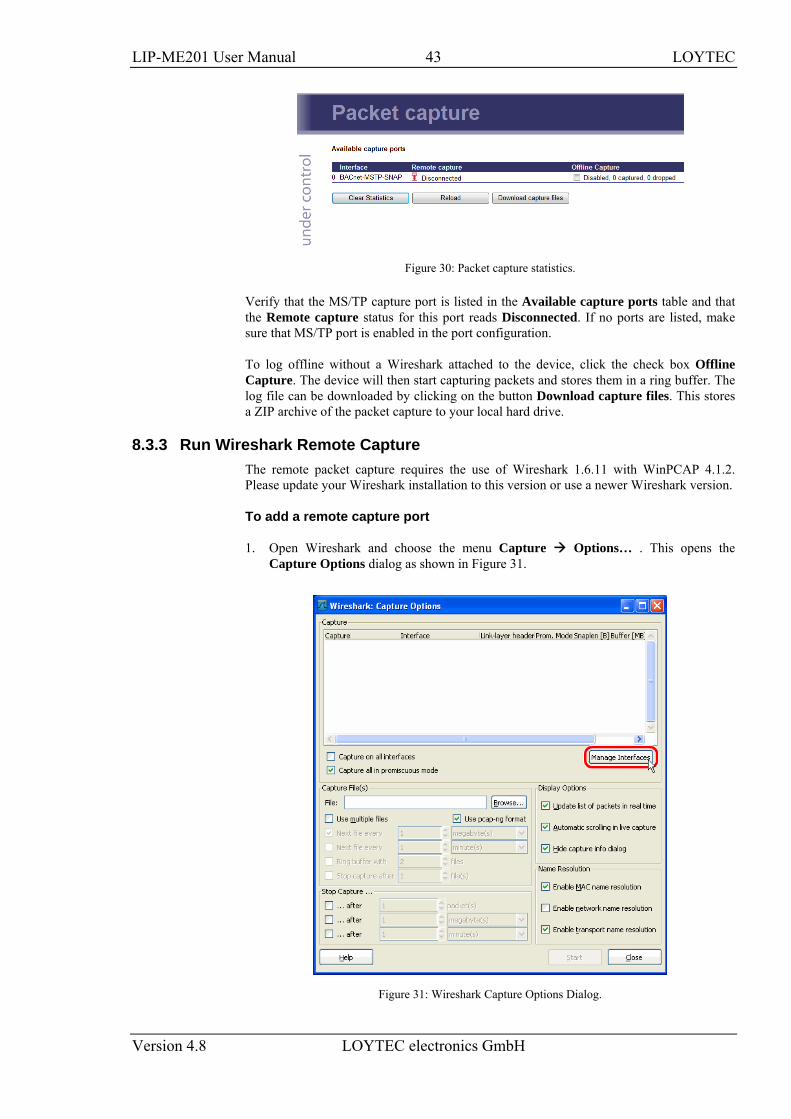
Figure 30: Packet capture statistics.
Verify that the MS/TP capture port is listed in the Available capture ports table and that the Remote capture status for this port reads Disconnected. If no ports are listed, make sure that MS/TP port is enabled in the port configuration.
To log offline without a Wireshark attached to the device, click the check box Offline Capture. The device will then start capturing packets and stores them in a ring buffer. The log file can be downloaded by clicking on the button Download capture files. This stores a ZIP archive of the packet capture to your local hard drive.
8.3.3 Run Wireshark Remote Capture The remote packet capture requires the use of Wireshark 1.6.11 with WinPCAP 4.1.2. Please update your Wireshark installation to this version or use a newer Wireshark version.
To add a remote capture port
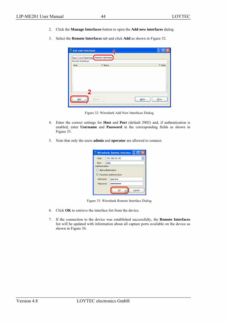
1. Open Wireshark and choose the menu Capture Options… . This opens the Capture Options dialog as shown in Figure 31.
Figure 31: Wireshark Capture Options Dialog.
LIP-ME201 User Manual 44 LOYTEC
Version 4.8 LOYTEC electronics GmbH
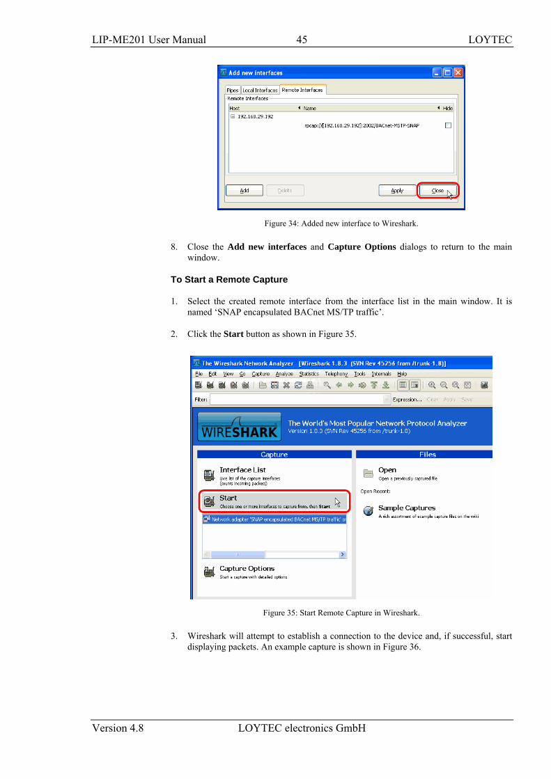
2. Click the Manage Interfaces button to open the Add new interfaces dialog.
3. Select the Remote Interfaces tab and click Add as shown in Figure 32.
Figure 32: Wireshark Add New Interfaces Dialog.
4. Enter the correct settings for Host and Port (default 2002) and, if authentication is enabled, enter Username and Password in the corresponding fields as shown in Figure 33.
5. Note that only the users admin and operator are allowed to connect.
Figure 33: Wireshark Remote Interface Dialog.
6. Click OK to retrieve the interface list from the device.
7. If the connection to the device was established successfully, the Remote Interfaces list will be updated with information about all capture ports available on the device as shown in Figure 34.
LIP-ME201 User Manual 45 LOYTEC
Version 4.8 LOYTEC electronics GmbH
Figure 34: Added new interface to Wireshark.
8. Close the Add new interfaces and Capture Options dialogs to return to the main window.
To Start a Remote Capture
1. Select the created remote interface from the interface list in the main window. It is named ‘SNAP encapsulated BACnet MS/TP traffic’.
2. Click the Start button as shown in Figure 35.
Figure 35: Start Remote Capture in Wireshark.
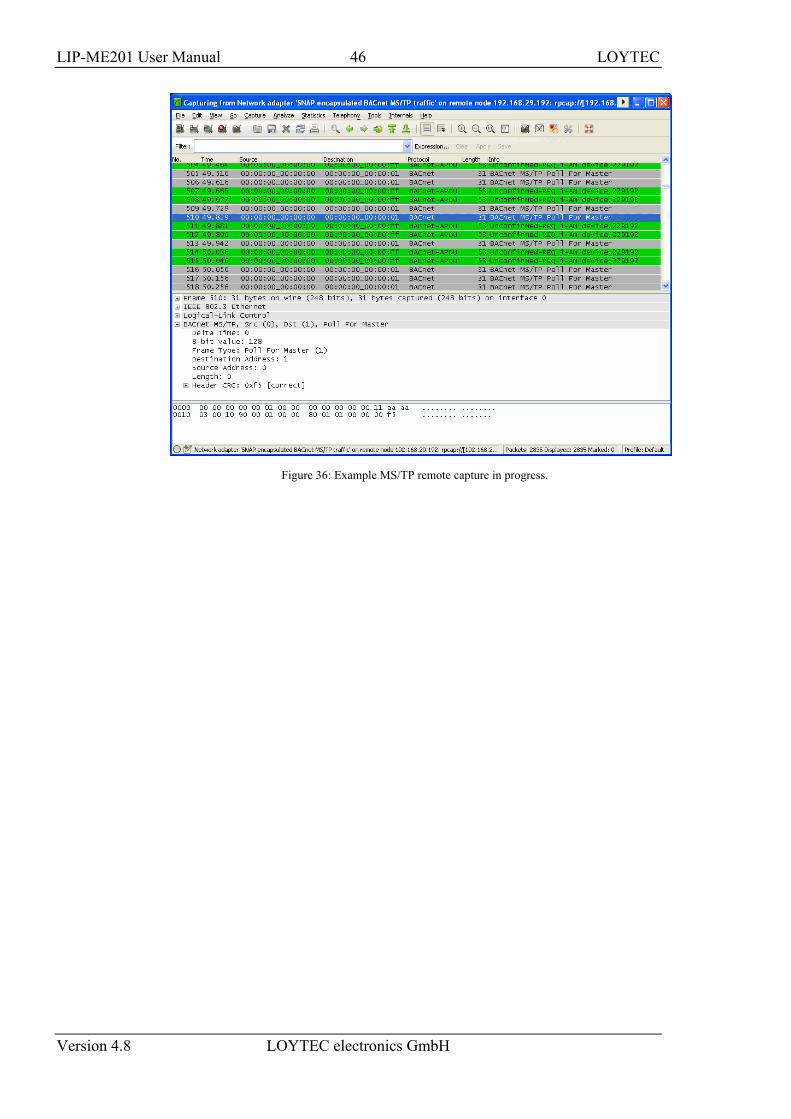
3. Wireshark will attempt to establish a connection to the device and, if successful, start displaying packets. An example capture is shown in Figure 36.
LIP-ME201 User Manual 46 LOYTEC
Version 4.8 LOYTEC electronics GmbH
Figure 36: Example MS/TP remote capture in progress.
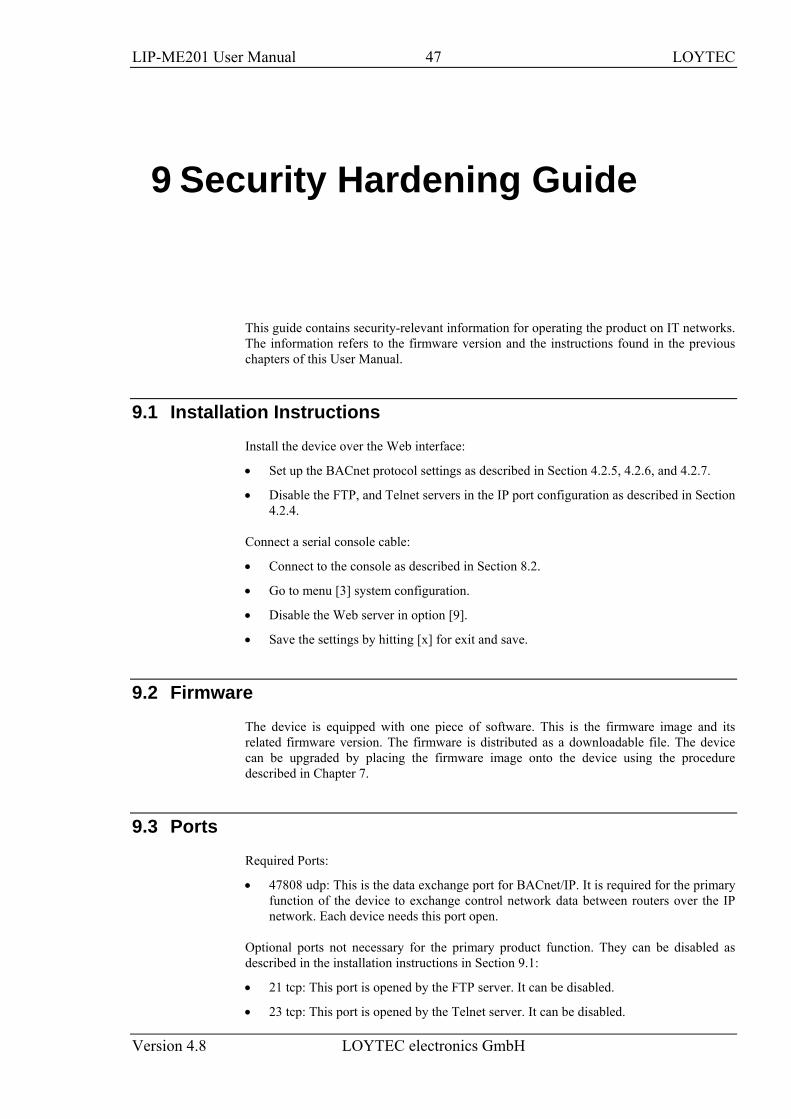
LIP-ME201 User Manual 47 LOYTEC
Version 4.8 LOYTEC electronics GmbH
9 Security Hardening Guide
This guide contains security-relevant information for operating the product on IT networks. The information refers to the firmware version and the instructions found in the previous chapters of this User Manual.
9.1 Installation Instructions Install the device over the Web interface:
• Set up the BACnet protocol settings as described in Section 4.2.5, 4.2.6, and 4.2.7.
• Disable the FTP, and Telnet servers in the IP port configuration as described in Section 4.2.4.
Connect a serial console cable:
• Connect to the console as described in Section 8.2.
• Go to menu [3] system configuration.
• Disable the Web server in option [9].
• Save the settings by hitting [x] for exit and save.
9.2 Firmware The device is equipped with one piece of software. This is the firmware image and its related firmware version. The firmware is distributed as a downloadable file. The device can be upgraded by placing the firmware image onto the device using the procedure described in Chapter 7.
9.3 Ports Required Ports:
• 47808 udp: This is the data exchange port for BACnet/IP. It is required for the primary function of the device to exchange control network data between routers over the IP network. Each device needs this port open.
Optional ports not necessary for the primary product function. They can be disabled as described in the installation instructions in Section 9.1:
• 21 tcp: This port is opened by the FTP server. It can be disabled.
• 23 tcp: This port is opened by the Telnet server. It can be disabled.
LIP-ME201 User Manual 48 LOYTEC
Version 4.8 LOYTEC electronics GmbH
• 80 tcp: This port is opened by the Web server. It can be disabled.
9.4 Services Required services:
• BACnet/IP: Primary function of the device. This service is in accordance with the standard ANSI/ASHRAE 135-2010.
Optional services not necessary for the primary product function. They can be disabled as described in the installation instructions in Section 9.1:
• HTTP: Web server. It provides a Web-based configuration UI.
• FTP: FTP server. It is used for firmware upgrade and access to the log file.
• Telnet: Telnet server. It provides access to the device console menu over the network.
9.5 Logging and Auditing The device contains a log file, which can be read out over FTP or the Web server. This log contains information when the device started and when crucial communication errors occur. Other information such user log-on are not logged as they are not part of the primary services of this device.
Logged events:
• Time of the last power-on reset of the LIP-ME201 device.
• Crucial communication errors.
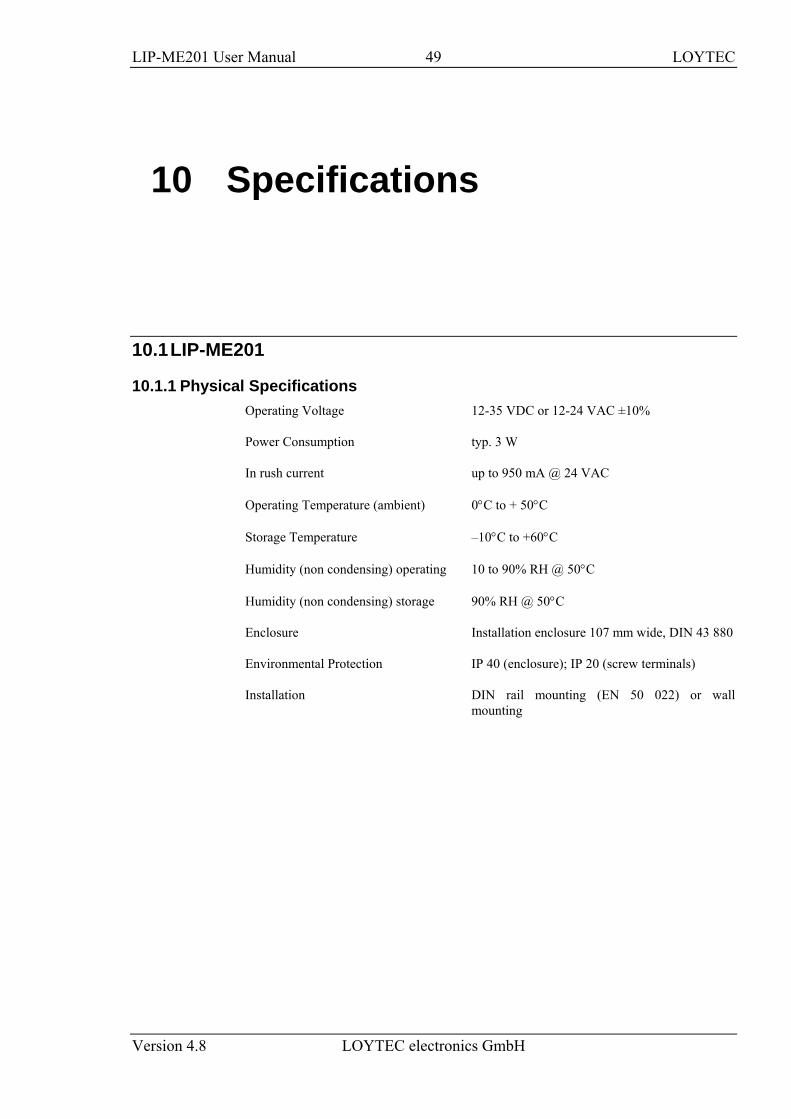
LIP-ME201 User Manual 49 LOYTEC
Version 4.8 LOYTEC electronics GmbH
10 Specifications
10.1 LIP-ME201
10.1.1 Physical Specifications Operating Voltage 12-35 VDC or 12-24 VAC ±10%
Power Consumption typ. 3 W
In rush current up to 950 mA @ 24 VAC
Operating Temperature (ambient) 0°C to + 50°C
Storage Temperature –10°C to +60°C
Humidity (non condensing) operating 10 to 90% RH @ 50°C
Humidity (non condensing) storage 90% RH @ 50°C
Enclosure Installation enclosure 107 mm wide, DIN 43 880
Environmental Protection IP 40 (enclosure); IP 20 (screw terminals)
Installation DIN rail mounting (EN 50 022) or wall mounting
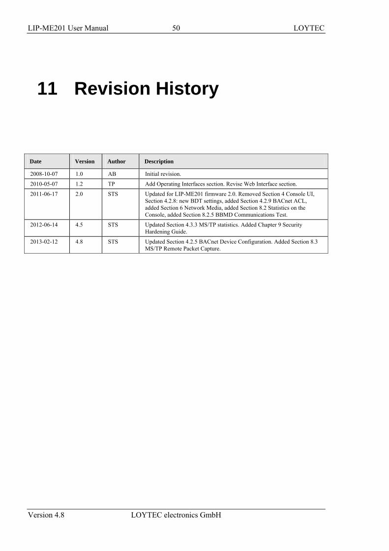
LIP-ME201 User Manual 50 LOYTEC
Version 4.8 LOYTEC electronics GmbH
11 Revision History
Date Version Author Description
2008-10-07 1.0 AB Initial revision.
2010-05-07 1.2 TP Add Operating Interfaces section. Revise Web Interface section.
2011-06-17 2.0 STS Updated for LIP-ME201 firmware 2.0. Removed Section 4 Console UI, Section 4.2.8: new BDT settings, added Section 4.2.9 BACnet ACL, added Section 6 Network Media, added Section 8.2 Statistics on the Console, added Section 8.2.5 BBMD Communications Test.
2012-06-14 4.5 STS Updated Section 4.3.3 MS/TP statistics. Added Chapter 9 Security Hardening Guide.
2013-02-12 4.8 STS Updated Section 4.2.5 BACnet Device Configuration. Added Section 8.3 MS/TP Remote Packet Capture.
![MUSANNA COLLEGE OF TECHNOLOGY Department of … · 1 17 ME201 KMK[ES] BCJ[ITS] 2 22 ME202 IAE[ES] PK[ITS] ... PHIL 4101 Oman Civilization B. Tech. 3 ALL 1 21 ME201 JOY[ELC] UM[ITS]](https://img.pdfslide.net/doc/110x75/5ae762577f8b9acc268e9773/musanna-college-of-technology-department-of-17-me201-kmkes-bcjits-2-22-me202.jpg)