Embed Size (px)
Citation preview
5 -1
5Steam Trap
5 -2
Steam Trap
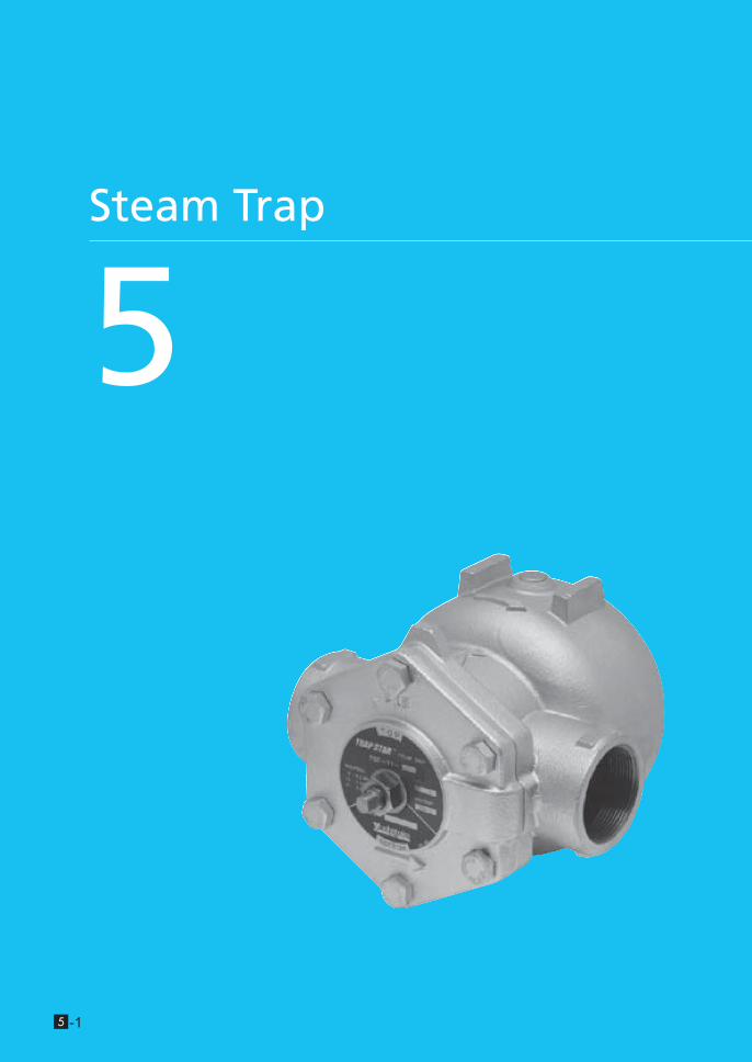
Step 0 Type/Structure/Features Please refer to this for type, structure and features of each
products.
Step 1 Selection Search the suitable product from ID-chart by application.
Details are on the products page.
Step 2 Sizing Confirm the note for selecting steam trap such as safety
factor to obtain the proper traps.
Step 3 Attentions for usage Please check some guidelines for optimal usage of Steam
Trap.
Reference material
Steam trap materials
What is Steam? This materials are described the purposes
of usage on each steam traps helping to energy savings
activities.
Steam Trap
5
Ste
am
Tra
p
www.yoshitake.jp5 -3
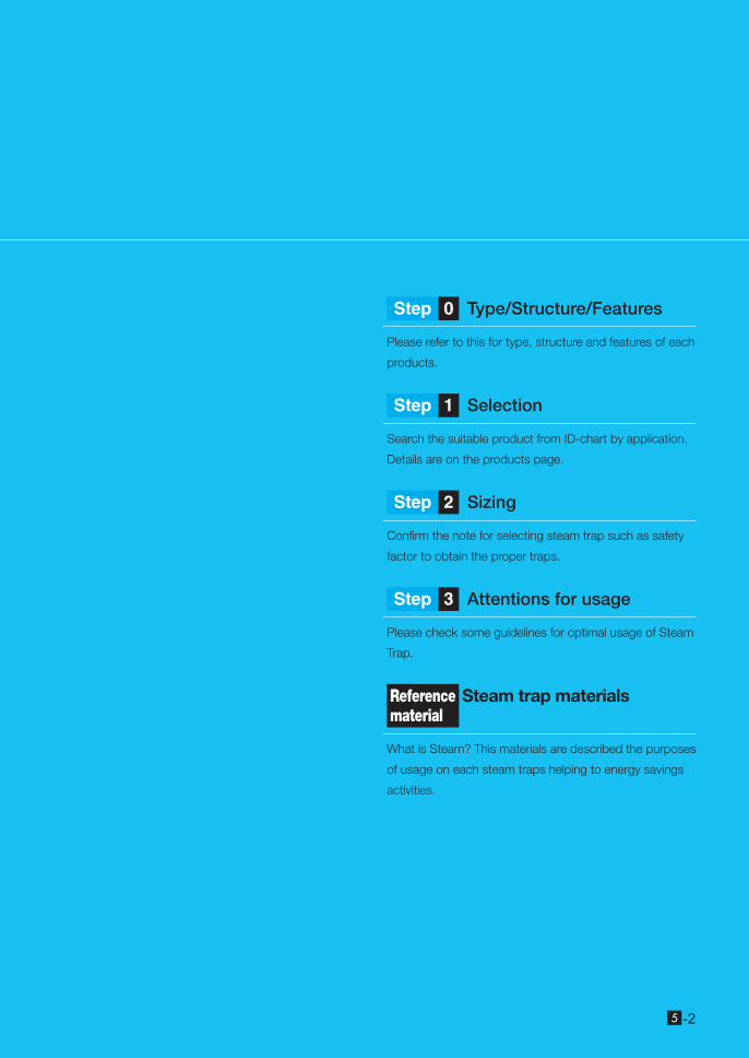
Types of Traps
What is trap?
A general term for self-acting valves which automatically discharge condensate from equipment or pipes
What is steam trap?
Trap used for steam equipment or steam pipes
What is condensate (drain)?
- Water senerated by condensation of steam in steam system- Oil and/or water generated in pneumatic line
TSF-10 TS-7TD-10NA TD-30NA
Thermodynamics typeActuates by the thermodynamic characteristics of steam and condensate.
Mechanical typeActuates by the specific gravity difference between steam and condensate.
Thermostatic typeActuates by the temperature difference between steam and condensate.
Steam Trap
5
Ste
am
Tra
p
www.yoshitake.jp 5 -4
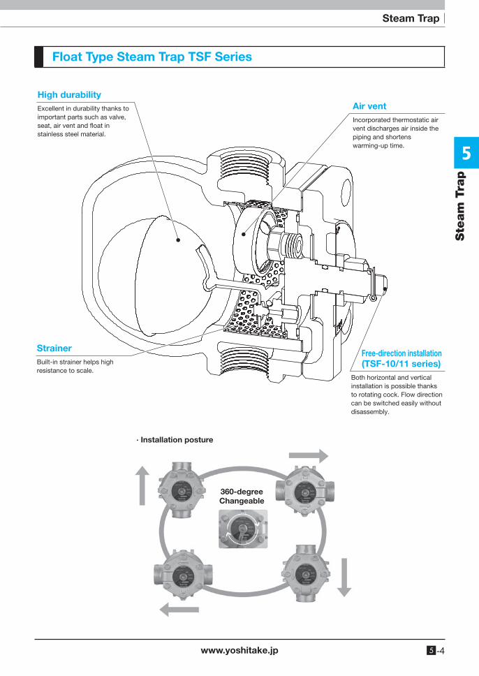
Float Type Steam Trap TSF Series
High durabilityExcellent in durability thanks to important parts such as valve, seat, air vent and �oat in stainless steel material.
Free-direction installation(TSF-10/11 series)
Both horizontal and vertical installation is possible thanks to rotating cock. Flow direction can be switched easily without disassembly.
StrainerBuilt-in strainer helps high resistance to scale.
Air ventIncorporated thermostatic air vent discharges air inside the piping and shortens warming-up time.
360-degreeChangeable
· Installation posture
Steam Trap
5
Ste
am
Tra
p
www.yoshitake.jp5 -5
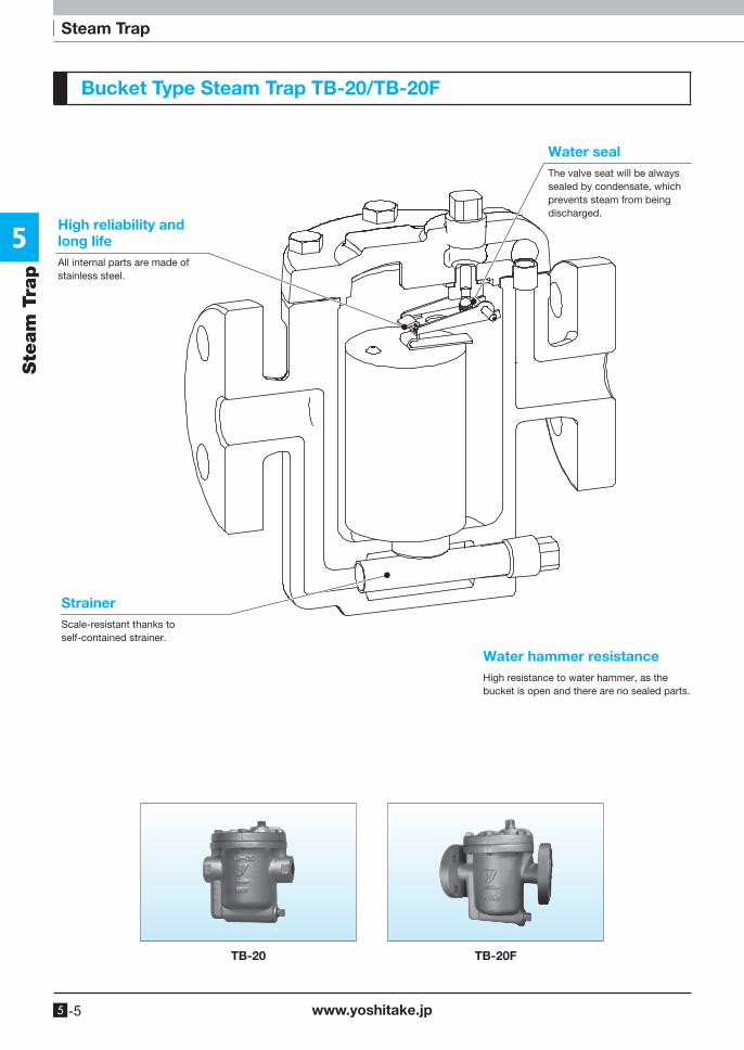
Bucket Type Steam Trap TB-20/TB-20F
TB-20 TB-20F
High reliability and long lifeAll internal parts are made of stainless steel.
StrainerScale-resistant thanks to self-contained strainer.
Water sealThe valve seat will be always sealed by condensate, which prevents steam from being discharged.
Water hammer resistanceHigh resistance to water hammer, as the bucket is open and there are no sealed parts.
Steam Trap
5
Ste
am
Tra
p
www.yoshitake.jp 5 -6
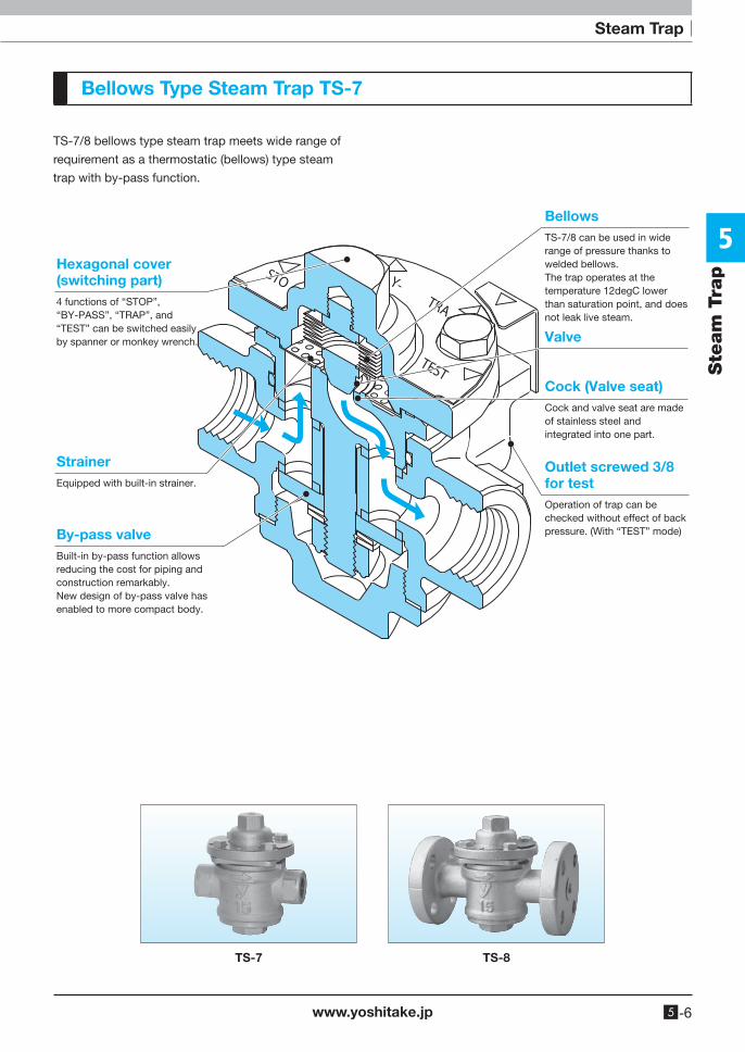
Bellows Type Steam Trap TS-7
TS-7/8 bellows type steam trap meets wide range of
requirement as a thermostatic (bellows) type steam
trap with by-pass function.
Hexagonal cover(switching part)4 functions of “STOP”, “BY-PASS”, “TRAP”, and “TEST” can be switched easily by spanner or monkey wrench.
StrainerEquipped with built-in strainer.
By-pass valveBuilt-in by-pass function allows reducing the cost for piping and construction remarkably.New design of by-pass valve has enabled to more compact body.
Outlet screwed 3/8 for testOperation of trap can be checked without effect of back pressure. (With “TEST” mode)
Cock (Valve seat)Cock and valve seat are made of stainless steel and integrated into one part.
BellowsTS-7/8 can be used in wide range of pressure thanks to welded bellows.The trap operates at the temperature 12degC lower than saturation point, and does not leak live steam.
Valve
TS-7 TS-8
Steam Trap
5
Ste
am
Tra
p
www.yoshitake.jp5 -7
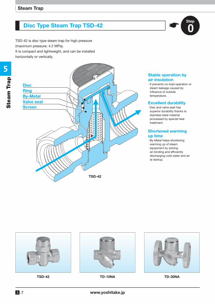
Disc Type Steam Trap TSD-42
TSD-42 is disc type steam trap for high pressure
(maximum pressure: 4.2 MPa).
It is compact and lightweight, and can be installed
horizontally or vertically.
TSD-42
DiscRing
Valve seatBy-Metal
Screen
Stable operation by air insulation∙ It prevents no-load operation or
steam leakage caused by in�uence of outside temperature.
Shortened warming up time∙ By-Metal helps shortening
warming up of steam equipment by solving air-binding and ef�ciently discharging cold water and air at startup.
Excellent durability∙ Disc and valve seat has
superior durability thanks to stainless steel material processed by special heat treatment.
TSD-42 TD-10NA TD-30NA
Steam Trap
5
Ste
am
Tra
p
www.yoshitake.jp 5 -8
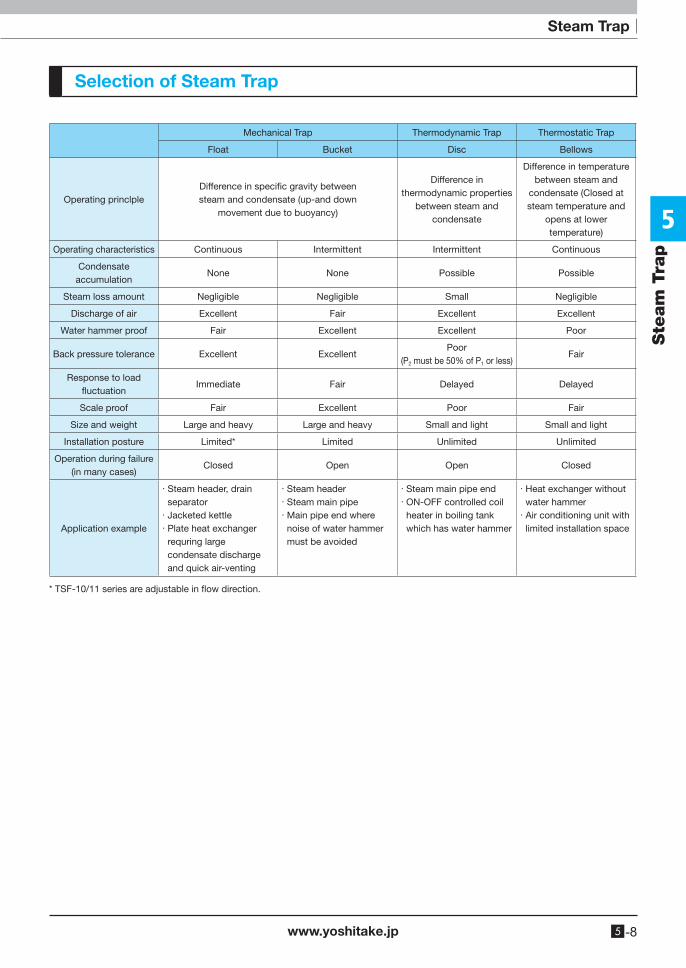
Mechanical Trap Thermodynamic Trap Thermostatic Trap
Float Bucket Disc Bellows
Operating princlpleDifference in specific gravity betweensteam and condensate (up-and down
movement due to buoyancy)
Difference in thermodynamic properties
between steam and condensate
Difference in temperature between steam and
condensate (Closed at steam temperature and
opens at lower temperature)
Operating characteristics Continuous Intermittent Intermittent Continuous
Condensate accumulation
None None Possible Possible
Steam loss amount Negligible Negligible Small Negligible
Discharge of air Excellent Fair Excellent Excellent
Water hammer proof Fair Excellent Excellent Poor
Back pressure tolerance Excellent ExcellentPoor
(P2 must be 50% of P1 or less)Fair
Response to load fluctuation
Immediate Fair Delayed Delayed
Scale proof Fair Excellent Poor Fair
Size and weight Large and heavy Large and heavy Small and light Small and light
Installation posture Limited* Limited Unlimited Unlimited
Operation during failure(in many cases)
Closed Open Open Closed
Application example
· Steam header, drain separator
· Jacketed kettle· Plate heat exchanger
requring large condensate discharge and quick air-venting
· Steam header· Steam main pipe· Main pipe end where
noise of water hammer must be avoided
· Steam main pipe end· ON-OFF controlled coil
heater in boiling tank which has water hammer
· Heat exchanger without water hammer
· Air conditioning unit with limited installation space
Selection of Steam Trap
* TSF-10/11 series are adjustable in flow direction.
Steam Trap
5
Ste
am
Tra
p
www.yoshitake.jp5 -9
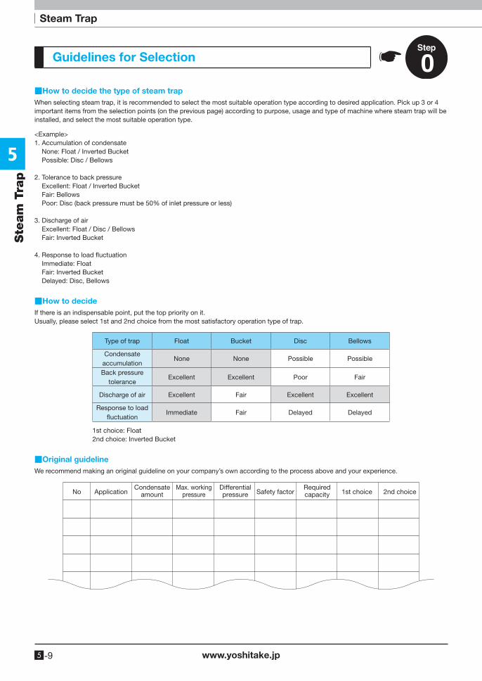
Guidelines for Selection
■How to decide the type of steam trapWhen selecting steam trap, it is recommended to select the most suitable operation type according to desired application. Pick up 3 or 4 important items from the selection points (on the previous page) according to purpose, usage and type of machine where steam trap will be installed, and select the most suitable operation type.
■How to decideIf there is an indispensable point, put the top priority on it.Usually, please select 1st and 2nd choice from the most satisfactory operation type of trap.
■Original guidelineWe recommend making an original guideline on your company’s own according to the process above and your experience.
<Example>1. Accumulation of condensate None: Float / Inverted Bucket Possible: Disc / Bellows
2. Tolerance to back pressure Excellent: Float / Inverted Bucket Fair: Bellows Poor: Disc (back pressure must be 50% of inlet pressure or less)
3. Discharge of air Excellent: Float / Disc / Bellows Fair: Inverted Bucket
4. Response to load fluctuation Immediate: Float Fair: Inverted Bucket Delayed: Disc, Bellows
Type of trap Float Bucket Disc Bellows
Condensate accumulation
None None Possible Possible
Back pressure tolerance
Excellent Excellent Poor Fair
Discharge of air Excellent Fair Excellent Excellent
Response to load fluctuation
Immediate Fair Delayed Delayed
1st choice: Float2nd choice: Inverted Bucket
No ApplicationCondensate
amountMax. working
pressureDifferentialpressure Safety factor
Requiredcapacity 1st choice 2nd choice
Steam Trap
5
Ste
am
Tra
p
www.yoshitake.jp 5 -10
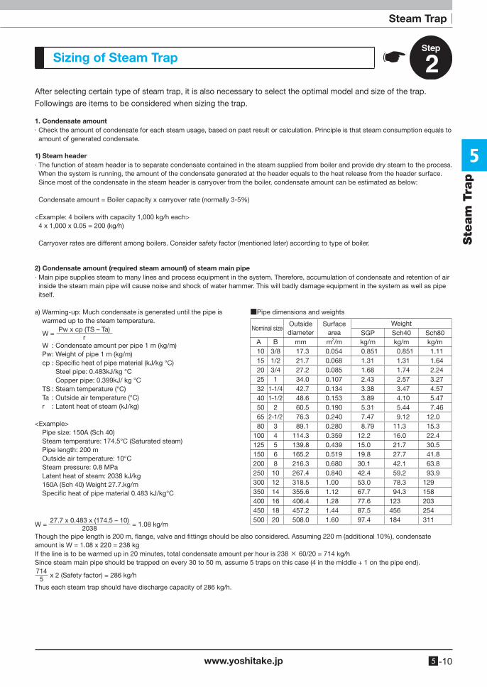
Sizing of Steam Trap
After selecting certain type of steam trap, it is also necessary to select the optimal model and size of the trap.
Followings are items to be considered when sizing the trap.
1. Condensate amount· Check the amount of condensate for each steam usage, based on past result or calculation. Principle is that steam consumption equals to
amount of generated condensate.
1) Steam header· The function of steam header is to separate condensate contained in the steam supplied from boiler and provide dry steam to the process.
When the system is running, the amount of the condensate generated at the header equals to the heat release from the header surface. Since most of the condensate in the steam header is carryover from the boiler, condensate amount can be estimated as below:
Condensate amount = Boiler capacity x carryover rate (normally 3-5%)
<Example: 4 boilers with capacity 1,000 kg/h each> 4 x 1,000 x 0.05 = 200 (kg/h)
Carryover rates are different among boilers. Consider safety factor (mentioned later) according to type of boiler.
a) Warming-up: Much condensate is generated until the pipe is warmed up to the steam temperature.
W = Pw x cp (TS – Ta)
r W : Condensate amount per pipe 1 m (kg/m) Pw : Weight of pipe 1 m (kg/m) cp : Specific heat of pipe material (kJ/kg °C) Steel pipe: 0.483kJ/kg °C Copper pipe: 0.399kJ/ kg °C TS : Steam temperature (°C) Ta : Outside air temperature (°C) r : Latent heat of steam (kJ/kg)
<Example> Pipe size: 150A (Sch 40) Steam temperature: 174.5°C (Saturated steam) Pipe length: 200 m Outside air temperature: 10°C Steam pressure: 0.8 MPa Latent heat of steam: 2038 kJ/kg 150A (Sch 40) Weight 27.7.kg/m Specific heat of pipe material 0.483 kJ/kg°C
■Pipe dimensions and weights
Nominal sizeOutside diameter
Surface area
WeightSGP Sch40 Sch80
A B mm m2/m kg/m kg/m kg/m 10 3/8 17.3 0.054 0.851 0.851 1.11 15 1/2 21.7 0.068 1.31 1.31 1.64 20 3/4 27.2 0.085 1.68 1.74 2.24 25 1 34.0 0.107 2.43 2.57 3.27 32 1-1/4 42.7 0.134 3.38 3.47 4.57 40 1-1/2 48.6 0.153 3.89 4.10 5.47 50 2 60.5 0.190 5.31 5.44 7.46 65 2-1/2 76.3 0.240 7.47 9.12 12.0 80 3 89.1 0.280 8.79 11.3 15.3100 4 114.3 0.359 12.2 16.0 22.4125 5 139.8 0.439 15.0 21.7 30.5150 6 165.2 0.519 19.8 27.7 41.8200 8 216.3 0.680 30.1 42.1 63.8250 10 267.4 0.840 42.4 59.2 93.9300 12 318.5 1.00 53.0 78.3 129350 14 355.6 1.12 67.7 94.3 158400 16 406.4 1.28 77.6 123 203450 18 457.2 1.44 87.5 456 254500 20 508.0 1.60 97.4 184 311
W = 27.7 x 0.483 x (174.5 – 10)
2038 = 1.08 kg/m
Though the pipe length is 200 m, flange, valve and fittings should be also considered. Assuming 220 m (additional 10%), condensate amount is W = 1.08 x 220 = 238 kgIf the line is to be warmed up in 20 minutes, total condensate amount per hour is 238 × 60/20 = 714 kg/hSince steam main pipe should be trapped on every 30 to 50 m, assume 5 traps on this case (4 in the middle + 1 on the pipe end).714
5 x 2 (Safety factor) = 286 kg/h
Thus each steam trap should have discharge capacity of 286 kg/h.
2) Condensate amount (required steam amount) of steam main pipe· Main pipe supplies steam to many lines and process equipment in the system. Therefore, accumulation of condensate and retention of air
inside the steam main pipe will cause noise and shock of water hammer. This will badly damage equipment in the system as well as pipe itself.
Steam Trap
5
Ste
am
Tra
p
www.yoshitake.jp5 -11
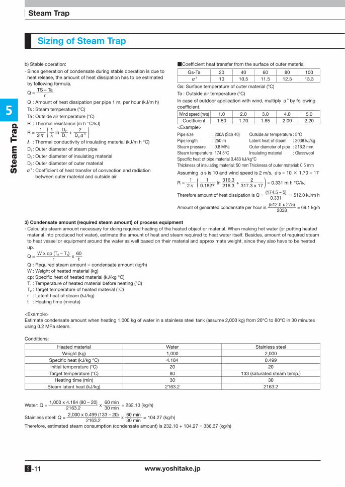
Sizing of Steam Trap
3) Condensate amount (required steam amount) of process equipment· Calculate steam amount necessary for doing required heating of the heated object or material. When making hot water (or putting heated
material into produced hot water), estimate the amount of heat and steam required to heat water itself. Besides, amount of required steam to heat vessel or equipment around the water as well based on their material and approximate weight, since they also have to be heated up.
Q = W x cp (T2 – T1)
r x
60t
Q : Required steam amount = condensate amount (kg/h) W : Weight of heated material (kg) cp: Specific heat of heated material (kJ/kg °C) T1 : Temperature of heated material before heating (°C) T2 : Target temperature of heated material (°C) r : Latent heat of steam (kJ/kg) t : Heating time (minute)
<Example>Estimate condensate amount when heating 1,000 kg of water in a stainless steel tank (assume 2,000 kg) from 20°C to 80°C in 30 minutes using 0.2 MPa steam.
Conditions:
Heated material Water Stainless steelWeight (kg) 1,000 2,000
Specific heat (kJ/kg °C) 4.184 0.499Initial temperature (°C) 20 20Target temperature (°C) 80 133 (saturated steam temp.)
Heating time (min) 30 30Steam latent heat (kJ/kg) 2163.2 2163.2
Water: Q = 1,000 x 4.184 (80 – 20)
2163.2 x
60 min30 min
= 232.10 (kg/h)
Stainless steel: Q = 2,000 x 0.499 (133 – 20)
2163.2 x
60 min30 min
= 104.27 (kg/h)
Therefore, estimated steam consumption (condensate amount) is 232.10 + 104.27 = 336.37 (kg/h)
b) Stable operation:
· Since generation of condensate during stable operation is due to heat release, the amount of heat dissipation has to be estimated by following formula.
Q = TS – Ta
r Q : Amount of heat dissipation per pipe 1 m, per hour (kJ/m h)
Ts : Steam temperature (°C)
Ta : Outside air temperature (°C)
R : Thermal resistance (m h °C/kJ)
R = 1
2π ( 1λ ln
D2
D1 +
2D3αs )
λ : Thermal conductivity of insulating material (kJ/m h °C)
D1 : Outer diameter of steam pipe
D2 : Outer diameter of insulating material
D3 : Outer diameter of outer material
αs : Coefficient of heat transfer of convection and radiation between outer material and outside air
■Coefficient heat transfer from the surface of outer material
Gs-Ta 20 40 60 80 100αs 10 10.5 11.5 12.3 13.3
Gs: Surface temperature of outer material (°C)
Ta : Outside air temperature (°C)
In case of outdoor application with wind, multiply αs by following coefficient.
Wind speed (m/s) 1.0 2.0 3.0 4.0 5.0Coefficient 1.50 1.70 1.85 2.00 2.20
<Example>
Assuming αs is 10 and wind speed is 2 m/s, αs = 10 × 1.70 = 17
R = 1
2π ( 10.1827
ln 316.3216.3
+ 2
317.3 x 17 ) = 0.331 m h °C/kJ
Therefore amount of heat dissipation is Q = (174.5 – 5)
0.331 = 512.0 kJ/m h
Amount of generated condensate per hour is (512.0 x 275)
2038 = 69.1 kg/h
Pipe size : 200A (Sch 40) Outside air temperature : 5°CPipe length : 250 m Latent heat of steam : 2038 kJ/kgSteam pressure : 0.8 MPa Outer diameter of pipe : 216.3 mmSteam temperature: 174.5°C Insulating material : GlasswoolSpecific heat of pipe material 0.483 kJ/kg°CThickness of insulating material: 50 mm Thickness of outer material: 0.5 mm
Steam Trap
5
Ste
am
Tra
p
www.yoshitake.jp 5 -12
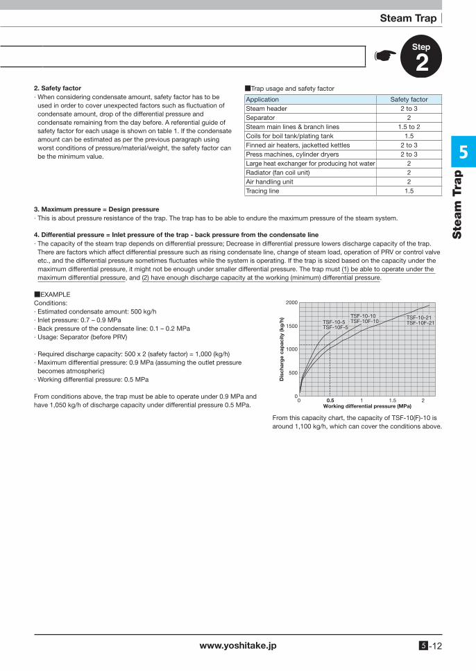
2. Safety factor· When considering condensate amount, safety factor has to be
used in order to cover unexpected factors such as fluctuation of condensate amount, drop of the differential pressure and condensate remaining from the day before. A referential guide of safety factor for each usage is shown on table 1. If the condensate amount can be estimated as per the previous paragraph using worst conditions of pressure/material/weight, the safety factor can be the minimum value.
3. Maximum pressure = Design pressure· This is about pressure resistance of the trap. The trap has to be able to endure the maximum pressure of the steam system.
4. Differential pressure = Inlet pressure of the trap - back pressure from the condensate line· The capacity of the steam trap depends on differential pressure; Decrease in differential pressure lowers discharge capacity of the trap.
There are factors which affect differential pressure such as rising condensate line, change of steam load, operation of PRV or control valve etc., and the differential pressure sometimes fluctuates while the system is operating. If the trap is sized based on the capacity under the maximum differential pressure, it might not be enough under smaller differential pressure. The trap must (1) be able to operate under the maximum differential pressure, and (2) have enough discharge capacity at the working (minimum) differential pressure.
■EXAMPLEConditions:· Estimated condensate amount: 500 kg/h· Inlet pressure: 0.7 – 0.9 MPa· Back pressure of the condensate line: 0.1 – 0.2 MPa· Usage: Separator (before PRV)
· Required discharge capacity: 500 x 2 (safety factor) = 1,000 (kg/h)· Maximum differential pressure: 0.9 MPa (assuming the outlet pressure
becomes atmospheric)· Working differential pressure: 0.5 MPa
From conditions above, the trap must be able to operate under 0.9 MPa and have 1,050 kg/h of discharge capacity under differential pressure 0.5 MPa.
From this capacity chart, the capacity of TSF-10(F)-10 is around 1,100 kg/h, which can cover the conditions above.
2000
1500
1000
500
0
Dis
char
ge
cap
acit
y (k
g/h
)
Working differential pressure (MPa)0 0.5 1 1.5 2
TSF-10-5TSF-10F-5
TSF-10-10TSF-10F-10
TSF-10-21TSF-10F-21
■Trap usage and safety factor
Application Safety factorSteam header 2 to 3Separator 2Steam main lines & branch lines 1.5 to 2Coils for boil tank/plating tank 1.5Finned air heaters, jacketted kettles 2 to 3Press machines, cylinder dryers 2 to 3Large heat exchanger for producing hot water 2Radiator (fan coil unit) 2Air handling unit 2Tracing line 1.5
Steam Trap
5
Ste
am
Tra
p
www.yoshitake.jp5 -13
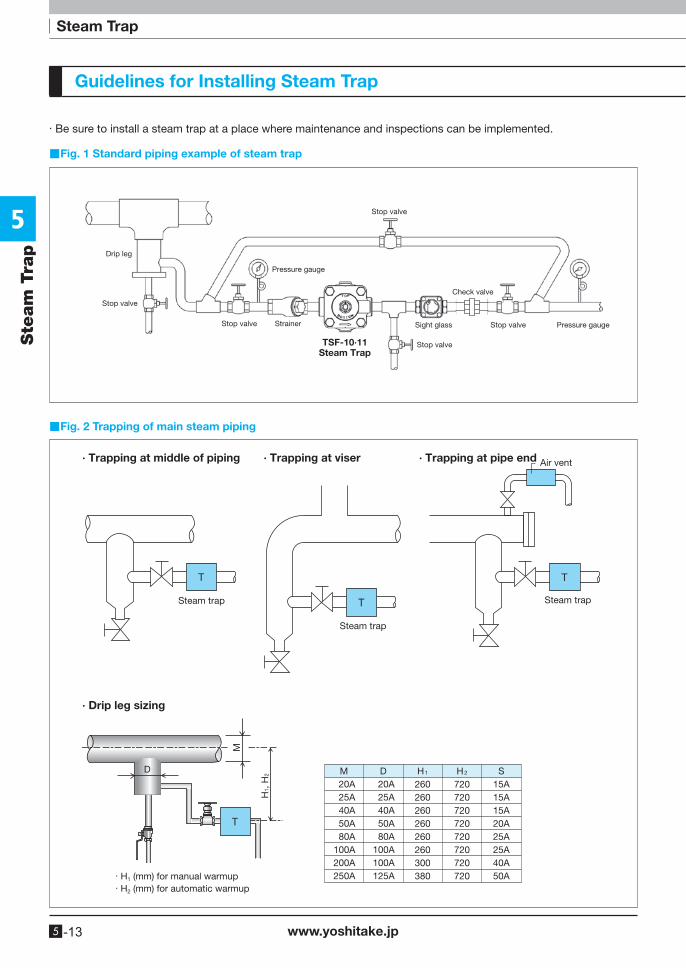
Guidelines for Installing Steam Trap
· Be sure to install a steam trap at a place where maintenance and inspections can be implemented.
Steam trap
Steam trap
Steam trap
Air vent∙ Trapping at middle of piping ∙ Trapping at viser ∙ Trapping at pipe end
∙ Drip leg sizing
D
H1,
H2
M
D M20A25A40A50A80A
100A200A250A
D20A25A40A50A80A
100A100A125A
H1
260260260260260260300380
H2
720720720720720720720720
S15A15A15A20A25A25A40A50A· H1 (mm) for manual warmup
· H2 (mm) for automatic warmup
■Fig. 2 Trapping of main steam piping
■Fig. 1 Standard piping example of steam trap
Drip leg
Stop valve
Stop valve
Stop valve
Stop valve
Stop valve
Check valve
Sight glass
Pressure gauge
Pressure gaugeStrainer
TSF-10∙11Steam Trap
Steam Trap
5
Ste
am
Tra
p
www.yoshitake.jp 5 -14
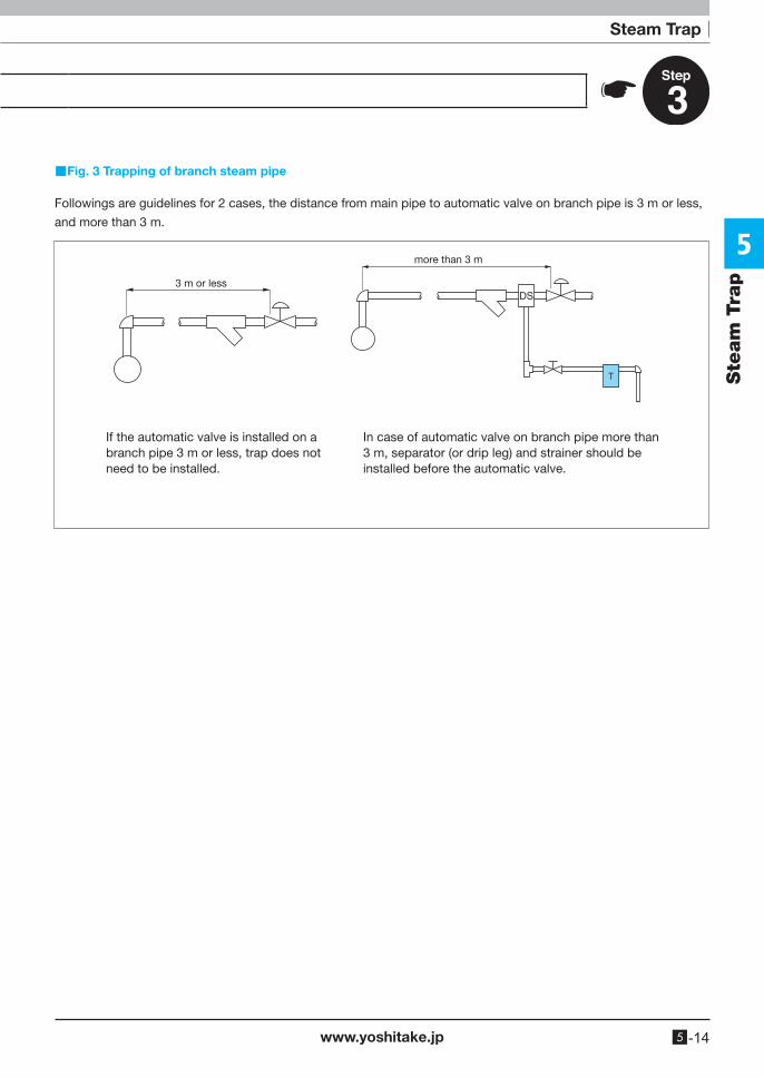
■Fig. 3 Trapping of branch steam pipe
Followings are guidelines for 2 cases, the distance from main pipe to automatic valve on branch pipe is 3 m or less,
and more than 3 m.
3 m or less
more than 3 m
If the automatic valve is installed on abranch pipe 3 m or less, trap does notneed to be installed.
In case of automatic valve on branch pipe more than3 m, separator (or drip leg) and strainer should beinstalled before the automatic valve.
DS
5
www.yoshitake.jp5 -15
Steam Trap – AnnexSte
am
Tra
p
Energy saving, one of the most important universal issues must be realized by the effort of all of us.
This guidebook presents operational principles and application examples of various types of steam
traps, which are based upon our 70-year’s experiences as a valve manufacturer. We believe that
these information will help you select a proper model and save energy.
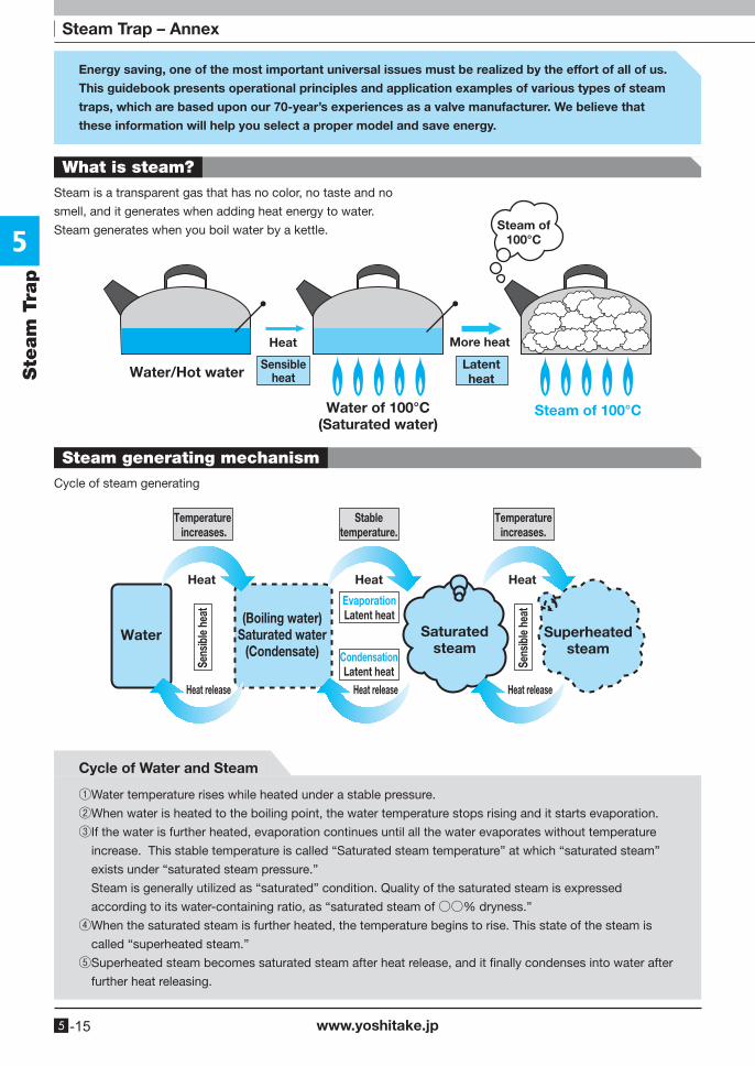
What is steam?
Steam generating mechanism
Steam is a transparent gas that has no color, no taste and no
smell, and it generates when adding heat energy to water.
Steam generates when you boil water by a kettle.
Cycle of steam generating
Water/Hot water
Heat
Sensibleheat
Latentheat
Water of 100°C(Saturated water)
More heat
Steam of 100°C
Steam of100°C
Heat release Heat release Heat release
Temperature increases.
Stabletemperature.
Temperatureincreases.
Heat Heat Heat
Water
Sens
ible
hea
t
Sens
ible
hea
t
(Boiling water)Saturated water
(Condensate)
EvaporationLatent heat
CondensationLatent heat
Saturatedsteam
Superheatedsteam
Cycle of Water and Steam
①Water temperature rises while heated under a stable pressure.
②When water is heated to the boiling point, the water temperature stops rising and it starts evaporation.
③ If the water is further heated, evaporation continues until all the water evaporates without temperature
increase. This stable temperature is called “Saturated steam temperature” at which “saturated steam”
exists under “saturated steam pressure.”
Steam is generally utilized as “saturated” condition. Quality of the saturated steam is expressed
according to its water-containing ratio, as “saturated steam of ○○% dryness.”
④ When the saturated steam is further heated, the temperature begins to rise. This state of the steam is
called “superheated steam.”
⑤ Superheated steam becomes saturated steam after heat release, and it finally condenses into water after
further heat releasing.
5
www.yoshitake.jp 5 -16
Steam Trap – Annex
Ste
am
Tra
p
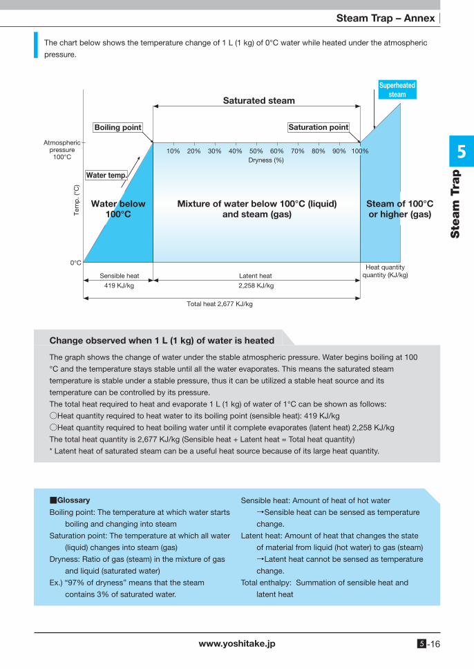
The chart below shows the temperature change of 1 L (1 kg) of 0°C water while heated under the atmospheric
pressure.
Atmosphericpressure100°C
0°C
Tem
p. (
°C)
Saturated steam
Superheatedsteam
Boiling point Saturation point
Water temp.
Dryness (%)10% 20% 30% 40% 50% 60% 70% 80% 90% 100%
Water below100°C
Mixture of water below 100°C (liquid)and steam (gas)
Steam of 100°Cor higher (gas)
Sensible heat
419 KJ/kg 2,258 KJ/kg
Latent heatHeat quantity
quantity (KJ/kg)
Total heat 2,677 KJ/kg
Change observed when 1 L (1 kg) of water is heated
The graph shows the change of water under the stable atmospheric pressure. Water begins boiling at 100
°C and the temperature stays stable until all the water evaporates. This means the saturated steam
temperature is stable under a stable pressure, thus it can be utilized a stable heat source and its
temperature can be controlled by its pressure.
The total heat required to heat and evaporate 1 L (1 kg) of water of 1°C can be shown as follows:
○Heat quantity required to heat water to its boiling point (sensible heat): 419 KJ/kg
○Heat quantity required to heat boiling water until it complete evaporates (latent heat) 2,258 KJ/kg
The total heat quantity is 2,677 KJ/kg (Sensible heat + Latent heat = Total heat quantity)
* Latent heat of saturated steam can be a useful heat source because of its large heat quantity.
■Glossary
Boiling point: The temperature at which water starts
boiling and changing into steam
Saturation point: The temperature at which all water
(liquid) changes into steam (gas)
Dryness: Ratio of gas (steam) in the mixture of gas
and liquid (saturated water)
Ex.) “97% of dryness” means that the steam
contains 3% of saturated water.
Sensible heat: Amount of heat of hot water
→Sensible heat can be sensed as temperature
change.
Latent heat: Amount of heat that changes the state
of material from liquid (hot water) to gas (steam)
→Latent heat cannot be sensed as temperature
change.
Total enthalpy: Summation of sensible heat and
latent heat
5
www.yoshitake.jp5 -17
Steam Trap – AnnexSte
am
Tra
p
Steam is a good heat source
Characteristics of steam
Steam is one of the best heat sources because:
○Heating temperature can be controlled by controlling steam pressure. ○Material can be heated uniformly by utilizing latent heat. ○ Material can be heated more effectively because steam provides latent heat which is
larger than sensible heat.
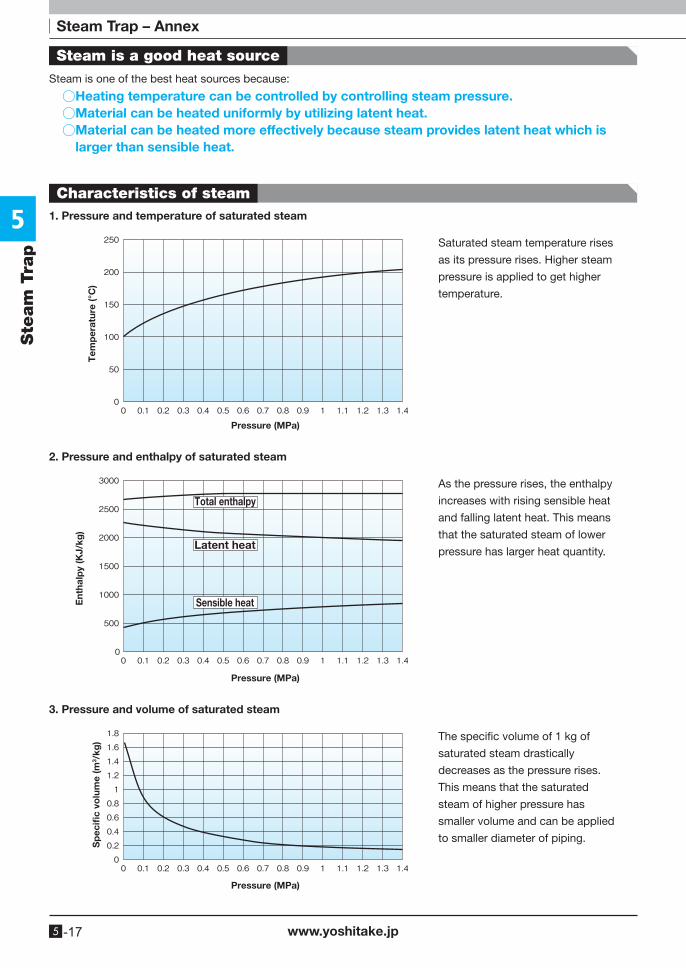
1. Pressure and temperature of saturated steam
2. Pressure and enthalpy of saturated steam
3. Pressure and volume of saturated steam
Tem
per
atur
e (°
C)
Pressure (MPa)
Ent
halp
y (K
J/kg
)
Pressure (MPa)
Total enthalpy
Latent heat
Sensible heat
Sp
ecifi
c vo
lum
e (m
3 /kg
)
Pressure (MPa)
Saturated steam temperature rises
as its pressure rises. Higher steam
pressure is applied to get higher
temperature.
As the pressure rises, the enthalpy
increases with rising sensible heat
and falling latent heat. This means
that the saturated steam of lower
pressure has larger heat quantity.
The specific volume of 1 kg of
saturated steam drastically
decreases as the pressure rises.
This means that the saturated
steam of higher pressure has
smaller volume and can be applied
to smaller diameter of piping.
5
www.yoshitake.jp 5 -18
Steam Trap – Annex
Ste
am
Tra
p
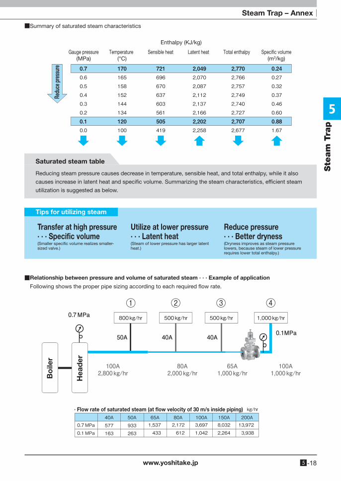
■Summary of saturated steam characteristics
Redu
ce pr
essu
reGauge pressure
(MPa)Temperature
(°C)Sensible heat
Enthalpy (KJ/kg)
Latent heat Total enthalpy Speci�c volume(m3/kg)
Saturated steam table
Reducing steam pressure causes decrease in temperature, sensible heat, and total enthalpy, while it also
causes increase in latent heat and specific volume. Summarizing the steam characteristics, efficient steam
utilization is suggested as below.
Transfer at high pressure· · · Specific volume(Smaller specific volume realizes smaller-sized valve.)
Utilize at lower pressure· · · Latent heat(Steam of lower pressure has larger latent heat.)
Reduce pressure· · · Better dryness(Dryness improves as steam pressure lowers, because steam of lower pressure requires lower total enthalpy.)
Tips for utilizing steam
■Relationship between pressure and volume of saturated steam · · · Example of application
Following shows the proper pipe sizing according to each required flow rate.
Bo
iler
Hea
der
· Flow rate of saturated steam (at flow velocity of 30 m/s inside piping)
5
www.yoshitake.jp5 -19
Steam Trap – AnnexSte
am
Tra
p
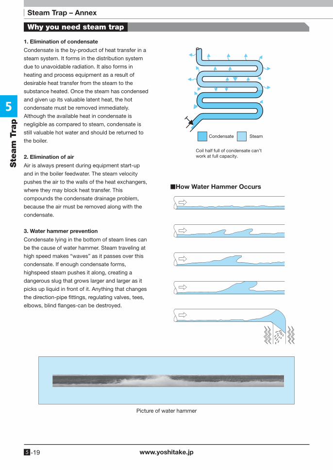
1. Elimination of condensate
Condensate is the by-product of heat transfer in a
steam system. It forms in the distribution system
due to unavoidable radiation. It also forms in
heating and process equipment as a result of
desirable heat transfer from the steam to the
substance heated. Once the steam has condensed
and given up its valuable latent heat, the hot
condensate must be removed immediately.
Although the available heat in condensate is
negligible as compared to steam, condensate is
still valuable hot water and should be returned to
the boiler.
2. Elimination of air
Air is always present during equipment start-up
and in the boiler feedwater. The steam velocity
pushes the air to the walls of the heat exchangers,
where they may block heat transfer. This
compounds the condensate drainage problem,
because the air must be removed along with the
condensate.
3. Water hammer prevention
Condensate lying in the bottom of steam lines can
be the cause of water hammer. Steam traveling at
high speed makes “waves” as it passes over this
condensate. If enough condensate forms,
highspeed steam pushes it along, creating a
dangerous slug that grows larger and larger as it
picks up liquid in front of it. Anything that changes
the direction-pipe fittings, regulating valves, tees,
elbows, blind flanges-can be destroyed.
Condensate Steam
Coil half full of condensate can’twork at full capacity.
■How Water Hammer Occurs
Picture of water hammer
Why you need steam trap
5
www.yoshitake.jp 5 -20
Steam Trap
Ste
am
Tra
p
Bucket Float Disc Bellows
Wafer By-pass Stainless steelBimetal
Right to Left Down to Up Up to DownConnector
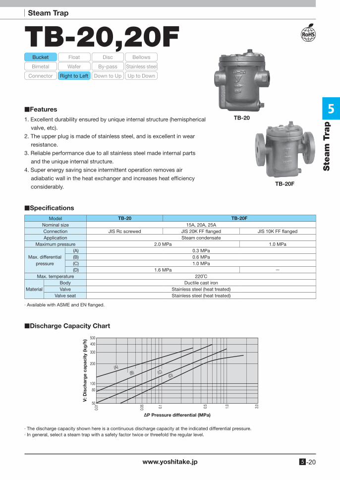
TB-20,20F
1. Excellent durability ensured by unique internal structure (hemispherical
valve, etc).
2. The upper plug is made of stainless steel, and is excellent in wear
resistance.
3. Reliable performance due to all stainless steel made internal parts
and the unique internal structure.
4. Super energy saving since intermittent operation removes air
adiabatic wall in the heat exchanger and increases heat efficiency
considerably.
■Features
■Specifications
Model TB-20 TB-20FNominal size 15A, 20A, 25AConnection JIS Rc screwed JIS 20K FF flanged JIS 10K FF flangedApplication Steam condensate
Maximum pressure 2.0 MPa 1.0 MPa
Max. differentialpressure
(A) 0.3 MPa(B) 0.6 MPa(C) 1.0 MPa(D) 1.6 MPa -
Max. temperature 220˚C
MaterialBody Ductile cast ironValve Stainless steel (heat treated)
Valve seat Stainless steel (heat treated)
· Available with ASME and EN flanged.
· The discharge capacity shown here is a continuous discharge capacity at the indicated differential pressure.· In general, select a steam trap with a safety factor twice or threefold the regular level.
■Discharge Capacity Chart
V: D
isch
arg
e ca
pac
ity
(kg
/h)
∆P Pressure differential (MPa)
TB-20
TB-20F
5
Ste
am
Tra
p
www.yoshitake.jp5 -21
TB-20, 20F
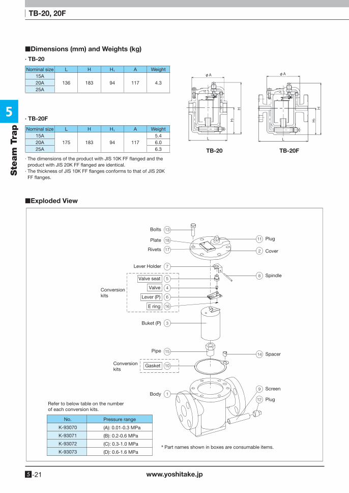
· The dimensions of the product with JIS 10K FF flanged and the product with JIS 20K FF flanged are identical.
· The thickness of JIS 10K FF flanges conforms to that of JIS 20K FF flanges.
■Dimensions (mm) and Weights (kg)
■Exploded View
∙ TB-20
∙ TB-20F
Nominal size L H H1 A Weight15A
136 183 94 117 4.320A25A
Nominal size L H H1 A Weight15A
175 183 94 1175.4
20A 6.025A 6.3
φA
L
H
H1
φA
L
HH1
Bolts
Plate
Rivets
Lever Holder
Buket (P)
Pipe
Body
Valve seat
Valve
Lever (P)
E ring
Gasket
Conversionkits
Conversionkits
Plug
Cover
Spindle
Spacer
Screen
Plug
* Part names shown in boxes are consumable items.
Refer to below table on the numberof each conversion kits.
No.
K-93070
K-93071
K-93072
K-93073
Pressure range
(A): 0.01-0.3 MPa
(B): 0.2-0.6 MPa
(C): 0.3-1.0 MPa
(D): 0.6-1.6 MPa
TB-20 TB-20F
5
www.yoshitake.jp 5 -22
Steam Trap
Ste
am
Tra
p
Bucket Float Disc Bellows
Wafer By-pass Stainless steelBimetal
Right to Left Down to Up Up to DownConnector
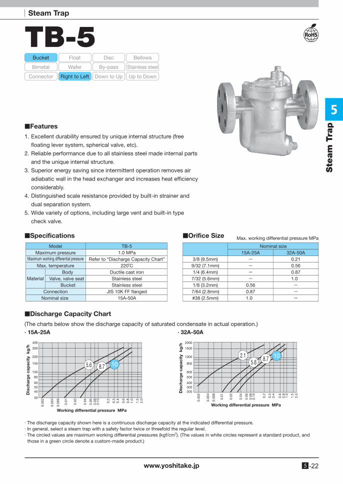
TB-5
1. Excellent durability ensured by unique internal structure (free
floating lever system, spherical valve, etc).
2. Reliable performance due to all stainless steel made internal parts
and the unique internal structure.
3. Superior energy saving since intermittent operation removes air
adiabatic wall in the head exchanger and increases heat efficiency
considerably.
4. Distinguished scale resistance provided by built-in strainer and
dual separation system.
5. Wide variety of options, including large vent and built-in type
check valve.
■Specifications
■Discharge Capacity Chart
■Features
■Orifice Size Max. working differential pressure MPa
(The charts below show the discharge capacity of saturated condensate in actual operation.)· 15A-25A · 32A-50A
TB-51.0 MPa
Refer to “Discharge Capacity Chart”220˚C
Ductile cast ironStainless steelStainless steel
JIS 10K FF �anged15A-50A
ModelMaximum pressure
Maximum working differential pressure
Max. temperature Body
Valve, valve seat Bucket
ConnectionNominal size
Material
400
300
200
150
100
80
30
0.00
2
0.00
4
0.00
6
0.01
0.02
0.04
0.06
0.08
0.10 0.2
0.3
0.4
0.6
0.8
1.0
1.5
2.0
405060
5.6 8.7 10
Working differential pressure MPa
Dis
char
ge
cap
acit
y k
g/h
2000
1500
1000
800
600
500
0.00
2
0.00
4
0.00
6
0.01
0.02
0.04
0.06
0.08
0.10 0.2
0.3
0.4
0.6
0.8
1.0
1.5
2.0
200300400
2.15.6 8.7 10
Working differential pressure MPa
Dis
char
ge
cap
acit
y k
g/h
· The discharge capacity shown here is a continuous discharge capacity at the indicated differential pressure.· In general, select a steam trap with a safety factor twice or threefold the regular level.· The circled values are maximum working differential pressures (kgf/cm2). (The values in white circles represent a standard product, and
those in a green circle denote a custom-made product.)
Nominal size15A-25A 32A-50A
3/8 (9.5mm) - 0.219/32 (7.1mm) - 0.561/4 (6.4mm) - 0.877/32 (5.6mm) - 1.01/8 (3.2mm) 0.56 -
7/64 (2.8mm) 0.87 -#38 (2.5mm) 1.0 -
5
Ste
am
Tra
p
www.yoshitake.jp5 -23
TB-5
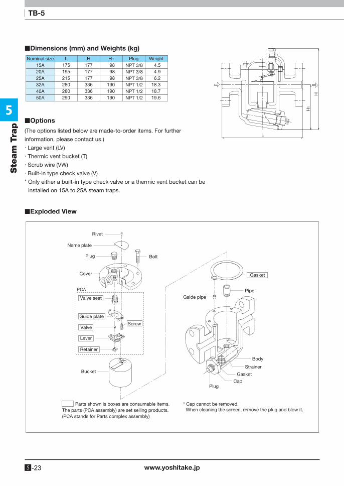
■Dimensions (mm) and Weights (kg)
■Exploded View
■Options
Nominal size15A20A25A32A40A50A
L175195215280280290
NPT 3/8NPT 3/8NPT 3/8NPT 1/2NPT 1/2NPT 1/2
H1 Plug WeightH177177177336336336
989898
190190190
4.54.96.2
18.318.719.6
(The options listed below are made-to-order items. For further
information, please contact us.)· Large vent (LV)· Thermic vent bucket (T)· Scrub wire (VW)· Built-in type check valve (V)* Only either a built-in type check valve or a thermic vent bucket can be
installed on 15A to 25A steam traps.
Rivet
Gasket
Gasket
Name plate
Plug
Plug
Cover
Bolt
Valve seat
Guide plate
Valve
Lever
Retainer
Screw
Bucket
PipeGalde pipe
Body
Strainer
Cap
* Cap cannot be removed. When cleaning the screen, remove the plug and blow it.
Parts shown is boxes are consumable items. The parts (PCA assembly) are set selling products.(PCA stands for Parts complex assembly)
5
www.yoshitake.jp 5 -24
Steam Trap
Ste
am
Tra
p
Bucket Float Disc Bellows
Wafer By-pass Stainless steelBimetal
Up to DownConnector Right to Left Down to Up
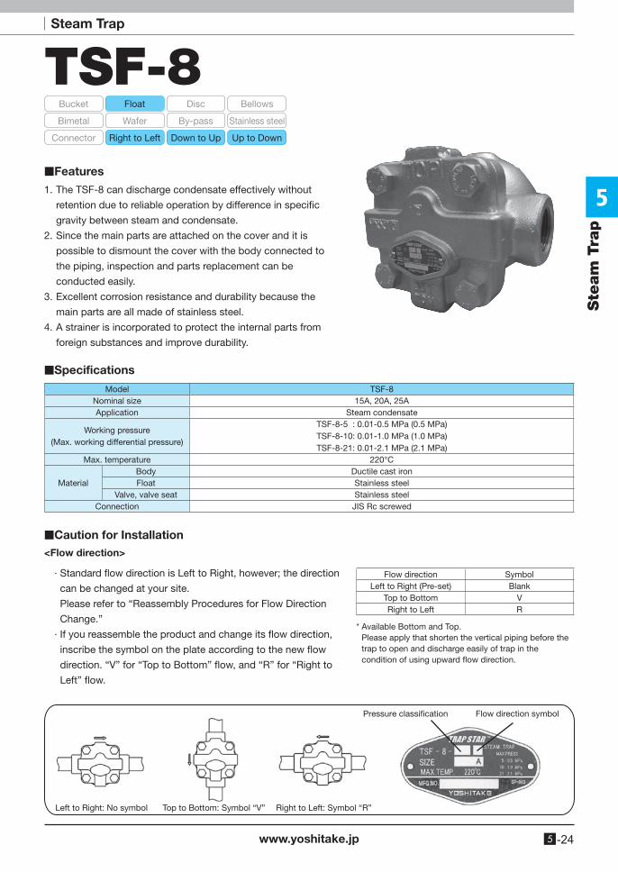
TSF-8
1. The TSF-8 can discharge condensate effectively without
retention due to reliable operation by difference in specific
gravity between steam and condensate.
2. Since the main parts are attached on the cover and it is
possible to dismount the cover with the body connected to
the piping, inspection and parts replacement can be
conducted easily.
3. Excellent corrosion resistance and durability because the
main parts are all made of stainless steel.
4. A strainer is incorporated to protect the internal parts from
foreign substances and improve durability.
■Features
■Specifications
■Caution for Installation<Flow direction>
Model TSF-8Nominal size 15A, 20A, 25AApplication Steam condensate
Working pressure(Max. working differential pressure)
TSF-8-5 : 0.01-0.5 MPa (0.5 MPa)TSF-8-10: 0.01-1.0 MPa (1.0 MPa)TSF-8-21: 0.01-2.1 MPa (2.1 MPa)
Max. temperature 220°C
MaterialBody Ductile cast ironFloat Stainless steel
Valve, valve seat Stainless steelConnection JIS Rc screwed
∙ Standard flow direction is Left to Right, however; the direction
can be changed at your site.
Please refer to “Reassembly Procedures for Flow Direction
Change.”
∙ If you reassemble the product and change its flow direction,
inscribe the symbol on the plate according to the new flow
direction. “V” for “Top to Bottom” flow, and “R” for “Right to
Left” flow.
Flow direction SymbolLeft to Right (Pre-set) Blank
Top to Bottom VRight to Left R
Left to Right: No symbol
Flow direction symbolPressure classi�cation
Top to Bottom: Symbol “V” Right to Left: Symbol “R”
* Available Bottom and Top.Please apply that shorten the vertical piping before the trap to open and discharge easily of trap in the condition of using upward flow direction.
5
www.yoshitake.jp5 -25
Ste
am
Tra
pTSF-8
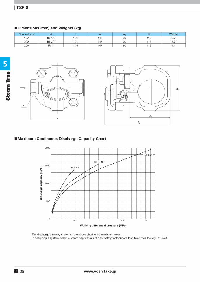
■Dimensions (mm) and Weights (kg)
■Maximum Continuous Discharge Capacity Chart
Nominal size d L A A1 H Weight15A Rc 1/2 121 147 90 113 3.720A Rc 3/4 121 147 90 113 3.725A Rc 1 145 147 90 113 4.1
d
L
A
H
A1
The discharge capacity shown on the above chart is the maximum value.In designing a system, select a steam trap with a sufficient safety factor (more than two times the regular level).
Working differential pressure (MPa)
Dis
char
ge
cap
acit
y (k
g/h
)
2000
1500
1000
500
00 0.5 1 1.5 2
TSF-8-5
TSF-8-10
TSF-8-21
5
www.yoshitake.jp 5 -26
Steam Trap
Ste
am
Tra
p
Bucket Float Disc Bellows
Wafer By-pass Stainless steelBimetal
Right to Left Down to Up Up to DownConnector
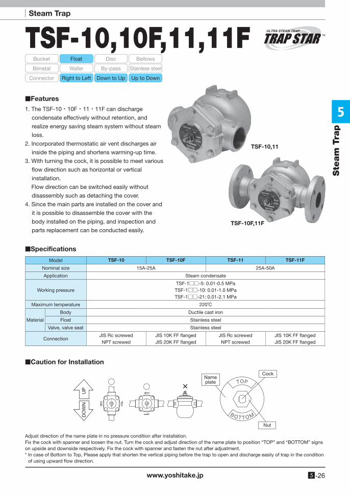
TSF-10,10F,11,11F
TSF-10,11
TSF-10F,11F
1. The TSF-10・10F・11・11F can discharge
condensate effectively without retention, and
realize energy saving steam system without steam
loss.
2. Incorporated thermostatic air vent discharges air
inside the piping and shortens warming-up time.
3. With turning the cock, it is possible to meet various
flow direction such as horizontal or vertical
installation.
Flow direction can be switched easily without
disassembly such as detaching the cover.
4. Since the main parts are installed on the cover and
it is possible to disassemble the cover with the
body installed on the piping, and inspection and
parts replacement can be conducted easily.
■Features
■Specifications
■Caution for Installation
Model TSF-10 TSF-10F TSF-11 TSF-11F
Nominal size 15A-25A 25A-50A
Application Steam condensate
Working pressureTSF-1□□-5: 0.01-0.5 MPaTSF-1□□-10: 0.01-1.0 MPaTSF-1□□-21: 0.01-2.1 MPa
Maximum temperature 220˚C
Material
Body Ductile cast iron
Float Stainless steel
Valve, valve seat Stainless steel
ConnectionJIS Rc screwedNPT screwed
JIS 10K FF flangedJIS 20K FF flanged
JIS Rc screwedNPT screwed
JIS 10K FF flangedJIS 20K FF flanged
UP
DO
WN
Nameplate
Cock
Nut
Adjust direction of the name plate in no pressure condition after installation.Fix the cock with spanner and loosen the nut. Turn the cock and adjust direction of the name plate to position “TOP” and “BOTTOM” signs on upside and downside respectively. Fix the cock with spanner and fasten the nut after adjustment.* In case of Bottom to Top, Please apply that shorten the vertical piping before the trap to open and discharge easily of trap in the condition
of using upward flow direction.
5
www.yoshitake.jp5 -27
Ste
am
Tra
pTSF-10, 10F, 11, 11F
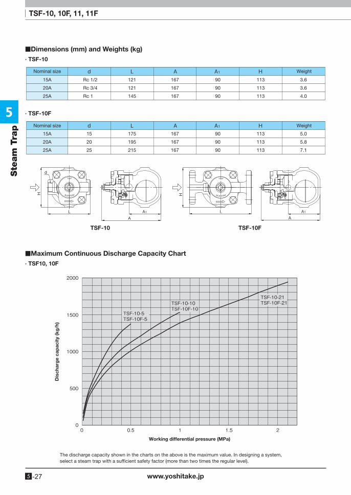
■Dimensions (mm) and Weights (kg)
■Maximum Continuous Discharge Capacity Chart∙ TSF10, 10F
∙ TSF-10
TSF-10 TSF-10F
∙ TSF-10F
Dis
char
ge
cap
acit
y (k
g/h
)
Working differential pressure (MPa)
Nominal size Weight
Rc 1/2
Rc 3/4
Rc 1
15A
20A
25A
121
121
145
167
167
167
90
90
90
113
113
113
3.6
3.6
4.0
WeightNominal size
15A
20A
25A
167
167
167
175
195
215
15
20
25
90
90
90
113
113
113
5.0
5.8
7.1
The discharge capacity shown in the charts on the above is the maximum value. In designing a system, select a steam trap with a sufficient safety factor (more than two times the regular level).
5
www.yoshitake.jp 5 -28
Ste
am
Tra
p
TSF-10, 10F, 11, 11F
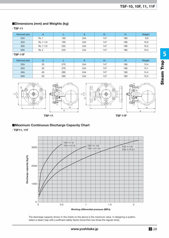
■Dimensions (mm) and Weights (kg)
■Maximum Continuous Discharge Capacity Chart∙ TSF11, 11F
∙ TSF-11
∙ TSF-11F
Dis
char
ge
cap
acit
y (k
g/h
)
Working differential pressure (MPa)
Nominal size Weight
Rc 1
Rc 1-1/4
Rc 1-1/2
Rc 2
25A
32A
40A
50A
190
190
205
220
244
244
244
244
147
147
147
147
186
186
186
186
9.9
10.0
10.2
10.5
Nominal size Weight
25A
32A
40A
50A
25
32
40
50
270
270
280
290
244
244
244
244
147
147
147
147
186
186
186
186
13.4
14.1
14.4
15.5
The discharge capacity shown in the charts on the above is the maximum value. In designing a system, select a steam trap with a sufficient safety factor (more than two times the regular level).
TSF-11 TSF-11F
5
www.yoshitake.jp5 -29
Steam TrapSte
am
Tra
p
Bucket Float Disc Bellows
Wafer By-pass Stainless steelBimetal
Right to Left Down to Up Up to DownConnector
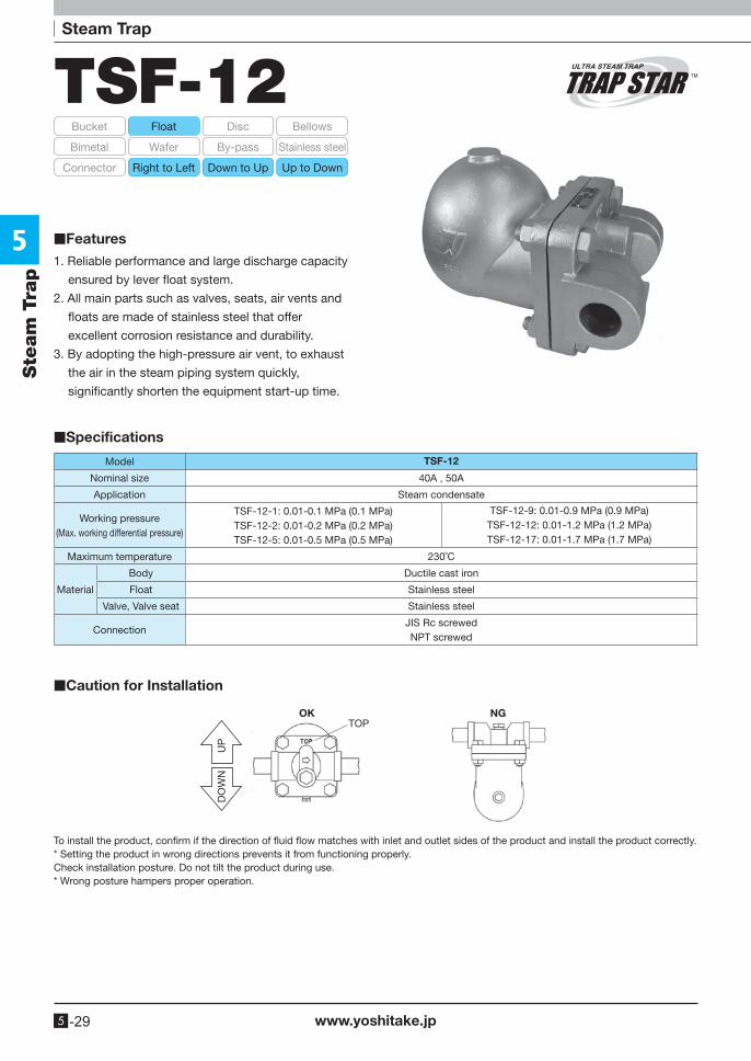
TSF-12
1. Reliable performance and large discharge capacity
ensured by lever float system.
2. All main parts such as valves, seats, air vents and
floats are made of stainless steel that offer
excellent corrosion resistance and durability.
3. By adopting the high-pressure air vent, to exhaust
the air in the steam piping system quickly,
significantly shorten the equipment start-up time.
■Features
■Specifications
■Caution for Installation
Model TSF-12
Nominal size 40A , 50A
Application Steam condensate
Working pressure(Max. working differential pressure)
TSF-12-1: 0.01-0.1 MPa (0.1 MPa)TSF-12-2: 0.01-0.2 MPa (0.2 MPa)TSF-12-5: 0.01-0.5 MPa (0.5 MPa)
TSF-12-9: 0.01-0.9 MPa (0.9 MPa)TSF-12-12: 0.01-1.2 MPa (1.2 MPa)TSF-12-17: 0.01-1.7 MPa (1.7 MPa)
Maximum temperature 230˚C
Material
Body Ductile cast iron
Float Stainless steel
Valve, Valve seat Stainless steel
ConnectionJIS Rc screwedNPT screwed
OK NGTOP
UP
DO
WN
To install the product, confirm if the direction of fluid flow matches with inlet and outlet sides of the product and install the product correctly.* Setting the product in wrong directions prevents it from functioning properly.Check installation posture. Do not tilt the product during use.* Wrong posture hampers proper operation.
5
www.yoshitake.jp 5 -30
Ste
am
Tra
p
TSF-12
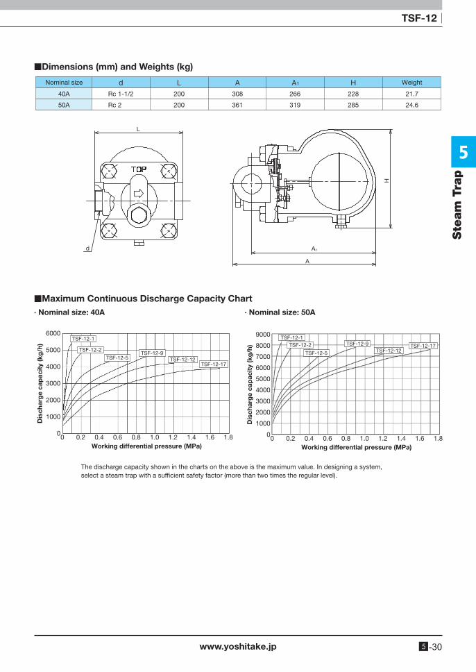
■Dimensions (mm) and Weights (kg)
Nominal size Weight
Rc 1-1/2
Rc 2
40A
50A
200
200
308
361
266
319
228
285
21.7
24.6
L
d
H
A
A1
■Maximum Continuous Discharge Capacity Chart∙ Nominal size: 40A ∙ Nominal size: 50A
6000
5000
4000
3000
2000
1000
0
Dis
char
ge
cap
acit
y (k
g/h
)
Working differential pressure (MPa)0 0.2 0.4 0.6 0.8 1.0 1.2 1.4 1.6 1.8
TSF-12-1
TSF-12-2
TSF-12-5TSF-12-9
TSF-12-12TSF-12-17
9000
8000
7000
6000
5000
4000
3000
2000
1000
0
Dis
char
ge
cap
acit
y (k
g/h
)
Working differential pressure (MPa)0 0.2 0.4 0.6 0.8 1.0 1.2 1.4 1.6 1.8
TSF-12-12TSF-12-17
TSF-12-1
TSF-12-5
TSF-12-9TSF-12-2
The discharge capacity shown in the charts on the above is the maximum value. In designing a system, select a steam trap with a sufficient safety factor (more than two times the regular level).
5
www.yoshitake.jp5 -31
Steam TrapSte
am
Tra
p
Bucket Float Disc Bellows
Wafer By-pass Stainless steelBimetal
Right to Left Down to Up Up to DownConnector
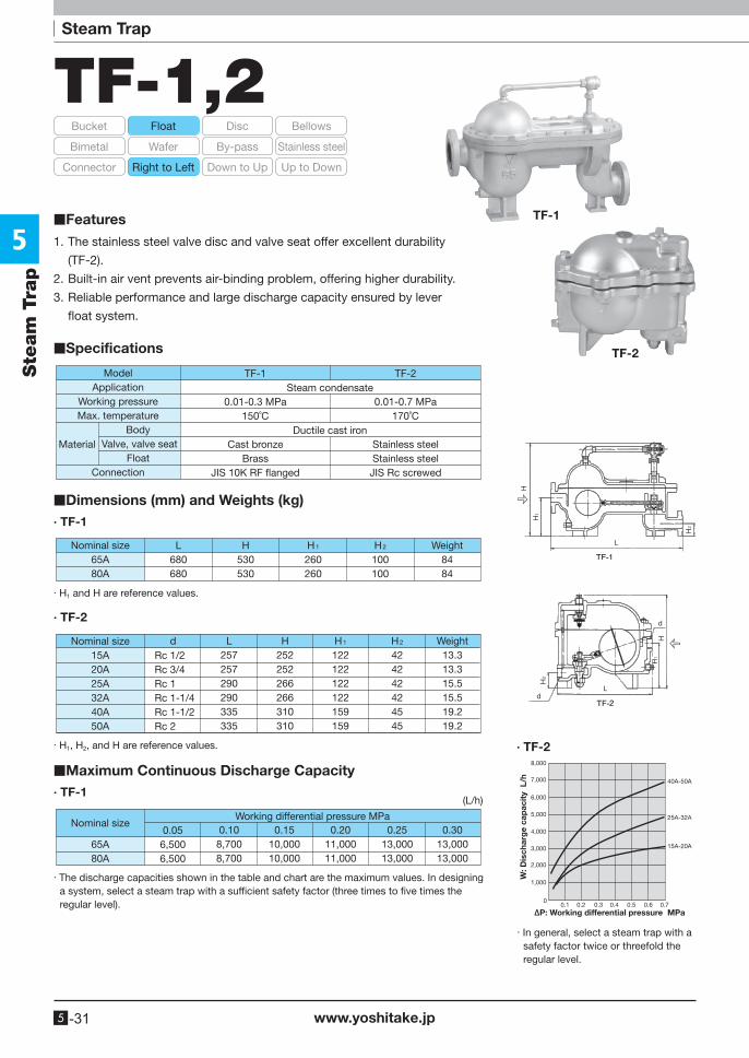
TF-1,2
1. The stainless steel valve disc and valve seat offer excellent durability
(TF-2).
2. Built-in air vent prevents air-binding problem, offering higher durability.
3. Reliable performance and large discharge capacity ensured by lever
float system.
■Specifications
■Features TF-1
TF-2
TF-1
0.01-0.3 MPa150˚C
Cast bronzeBrass
JIS 10K RF �anged
ModelApplication
Working pressureMax. temperature
Body Valve, valve seat
FloatConnection
TF-2
0.01-0.7 MPa170˚C
Stainless steelStainless steel
JIS Rc screwed
Material
Steam condensate
Ductile cast iron
· TF-1
· TF-1 (L/h)
■Dimensions (mm) and Weights (kg)
■Maximum Continuous Discharge Capacity
Nominal size65A80A
Weight8484
H530530
L680680
H1
260260
H2
100100
· H1 and H are reference values.
· TF-2
Nominal size15A20A25A32A40A50A
Weight13.313.315.515.519.219.2
dRc 1/2Rc 3/4Rc 1Rc 1-1/4Rc 1-1/2Rc 2
L257257290290335335
H1
122122122122159159
H252252266266310310
H2
424242424545
· H1, H2, and H are reference values.
65A80A
Nominal size0.05
6,5006,500
0.108,7008,700
0.2011,00011,000
0.1510,00010,000
Working differential pressure MPa0.25
13,00013,000
0.3013,00013,000
· The discharge capacities shown in the table and chart are the maximum values. In designing a system, select a steam trap with a sufficient safety factor (three times to five times the regular level).
· In general, select a steam trap with a safety factor twice or threefold the regular level.
8,000
7,000
6,000
5,000
2,000
1,000
3,000
4,000
00.1 0.2 0.3 0.4 0.5 0.6 0.7
W: D
isch
arg
e ca
pac
ity
L/h
∆P: Working differential pressure MPa
40A-50A
25A-32A
15A-20A
· TF-2
5
www.yoshitake.jp 5 -32
Steam Trap
Ste
am
Tra
p
Bucket Float Disc Bellows
Wafer By-pass Stainless steelBimetal
Right to Left Down to Up Up to DownConnector
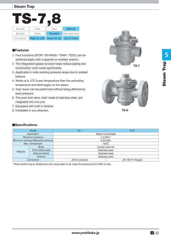
TS-7,8
TS-7
TS-8
1. Four functions (STOP / BY-PASS / TRAP / TEST) can be
switched easily with a spanner or monkey wrench.
2. The integrated bypass function helps reduce piping and
construction work costs significantly.
3. Applicable in wide working pressure range due to welded
bellows.
4. Works at a 12˚C lower temperature than the saturating
temperature and discharges no live steam.
5. Trap check can be performed without being affected by
back pressure.
6. The cock and valve, both made of stainless steel, are
integrated into one unit.
7. Equipped with built-in strainer.
8. Installable in any direction.
■Specifications
TS-7
JIS Rc screwed
TS-8
JIS 10K FF �anged
Steam condensate1.0 MPa *0.03 MPa
183˚CDuctile cast ironStainless steelStainless steelStainless steel
ModelApplication
Maximum pressureMinimum working differential pressure
Max. temperature Body
Cock (Valve seat) Bellows (Valve)
StrainerConnection
Material
* When performing an airtightness test using water or air, keep the pressure at 0.5 MPa or less.
■Features
5
www.yoshitake.jp5 -33
Ste
am
Tra
pTS-7, 8
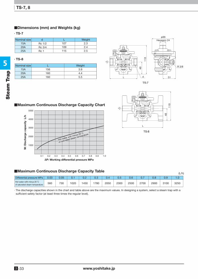
Nominal size15A20A25A
Weight2.32.42.5
d Rc 1/2Rc 3/4Rc 1
L107109115
· TS-8
Nominal size15A20A25A
Weight3.94.45.5
L156160160
5000
4000
3000
2000
1000
0.1 0.2 0.3 0.4 0.5 0.6 0.7 0.8 0.9 1.0
W: D
isch
arg
e ca
pac
ity
L/h
∆P: Working differential pressure MPa
Hot water with minus 20 ˚C
of saturated steam temperature
Hexagon 24
R 3/8
0.03
560
Differential pressure MPa
Hot water with minus 20 ˚Cof saturated steam temperature
0.05
730
0.1
1020
0.2
1450
0.3
1780
0.4
2050
0.5
2300
0.6
2500
0.7
2700
0.8
2900
0.9
3100
1.0
3250
· The discharge capacities shown in the chart and table above are the maximum values. In designing a system, select a steam trap with a sufficient safety factor (at least three times the regular level).
· TS-7
■Dimensions (mm) and Weights (kg)
■Maximum Continuous Discharge Capacity Chart
■Maximum Continuous Discharge Capacity Table (L/h)
5
www.yoshitake.jp 5 -34
Steam Trap
Ste
am
Tra
p
Bucket Float Disc Bellows
Wafer By-pass Stainless steelBimetal
Right to Left Down to Up Up to DownConnector
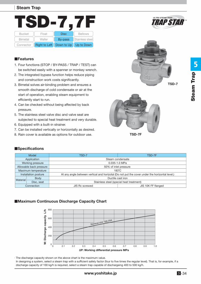
TSD-7,7F
TSD-7
TSD-7F
1. Four functions (STOP / BY-PASS / TRAP / TEST) can
be switched easily with a spanner or monkey wrench.
2. The integrated bypass function helps reduce piping
and construction work costs significantly.
3. Bimetal solves air-binding problem and ensures a
smooth discharge of cold condensate or air at the
start of operation, enabling steam equipment to
efficiently start to run.
4. Can be checked without being affected by back
pressure.
5. The stainless steel valve disc and valve seat are
subjected to special heat treatment and very durable.
6. Equipped with a built-in strainer.
7. Can be installed vertically or horizontally as desired.
8. Rain cover is available as options for outdoor use.
■Specifications
■Features
■Maximum Continuous Discharge Capacity Chart
TSD-7
JIS Rc screwed
ModelApplication
Working pressureAllowable back pressureMaximum temperature
Installation posture Body
Disc, seatConnection
TSD-7F
JIS 10K FF �anged
Steam condensate0.035-1.0 MPa
50% of inlet pressure 183˚C
At any angle between vertical and horizotal (Do not put the cover under the horizontal level.)Ductile cast iron
Stainless steel (special heat treatment)Material
200
0
400
600
800
0.10 0.2 0.3 0.4 0.5 0.6 0.7 0.8 0.9 1.0
W: D
isch
arg
e ca
pac
ity
L/h
∆P: Working differential pressure MPa
Nominal size 15A-25A
· The discharge capacity shown on the above chart is the maximum value. In designing a system, select a steam trap with a sufficient safety factor (four to five times the regular level). That is, for example, if a
discharge capacity of 100 kg/h is required, select a steam trap capable of dischargeing 400 to 500 kg/h.
5
www.yoshitake.jp5 -35
Ste
am
Tra
pTSD-7, 7F
Hexagon 24
R 3/8
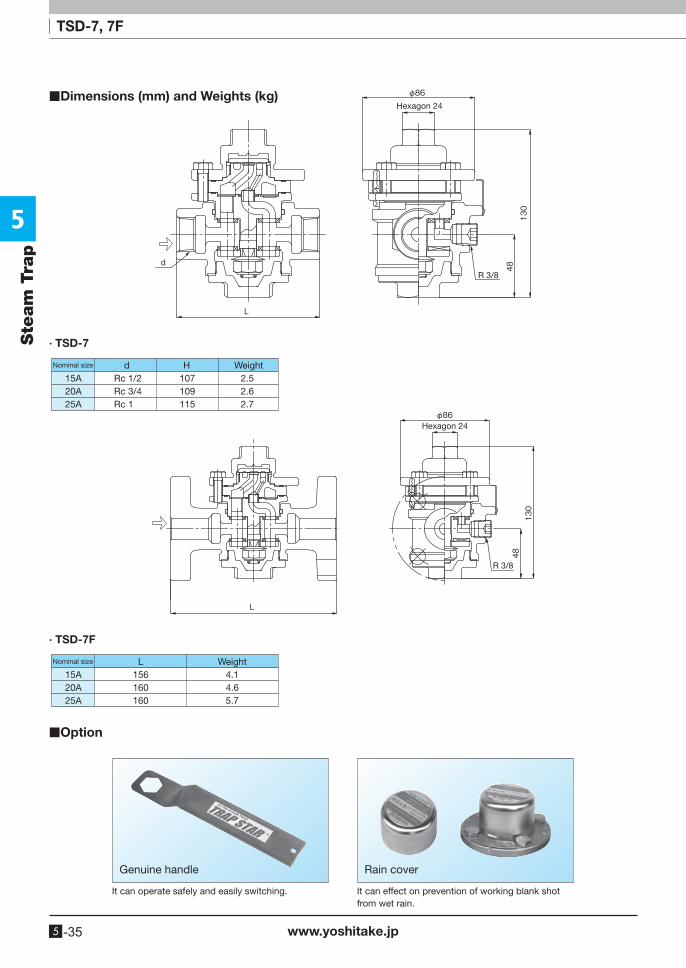
· TSD-7
Nominal size H Weightd2.52.62.7
15A20A25A
107109115
Rc 1/2Rc 3/4Rc 1
Hexagon 24
R 3/8
· TSD-7F
Nominal size WeightL15A20A25A
4.14.65.7
156160160
■Dimensions (mm) and Weights (kg)
■Option
Rain coverGenuine handle
It can operate safely and easily switching. It can effect on prevention of working blank shot from wet rain.
5
www.yoshitake.jp 5 -36
Steam Trap
Ste
am
Tra
p
STO
P
TRA
P
TES
T
BY
-P
AS
S
STOP
TRAPTEST
BY-PASS
TEST
BY-PASS
TRAP
STOP
TEST
BY-
PASSTRAP
STOP
STOP BY-PASS TRAP TEST
CondensateSteam
Trap
Bypass
TrapBellows
Pos
ition
Con
vent
iona
lp
ipin
gO
per
atio
n
Strainer
Bypass pipe Close Close
Open Open Open
Open(Test line)
Outlet for testing
Close
Close
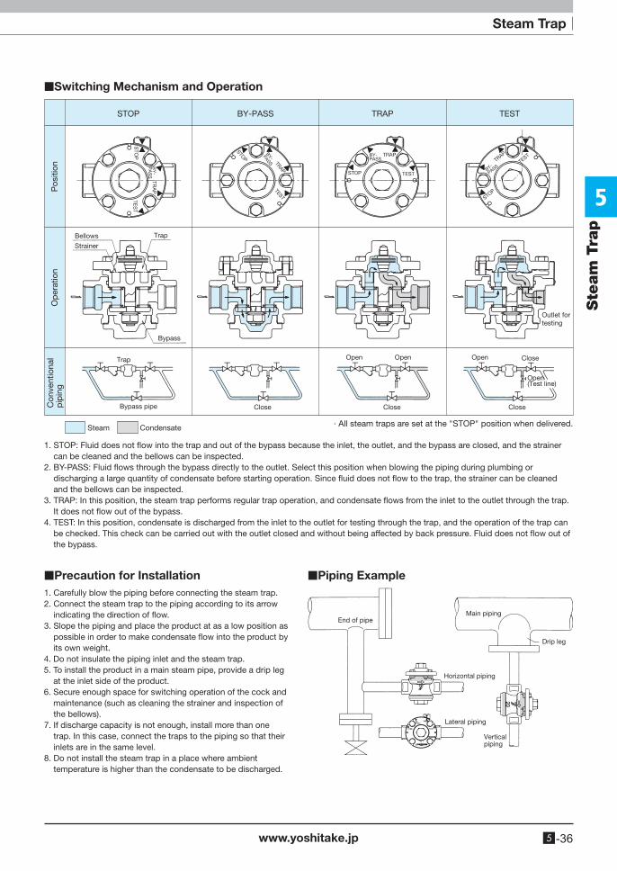
· All steam traps are set at the "STOP" position when delivered.
1. STOP: Fluid does not flow into the trap and out of the bypass because the inlet, the outlet, and the bypass are closed, and the strainer can be cleaned and the bellows can be inspected.
2. BY-PASS: Fluid flows through the bypass directly to the outlet. Select this position when blowing the piping during plumbing or discharging a large quantity of condensate before starting operation. Since fluid does not flow to the trap, the strainer can be cleaned and the bellows can be inspected.
3. TRAP: In this position, the steam trap performs regular trap operation, and condensate flows from the inlet to the outlet through the trap. It does not flow out of the bypass.
4. TEST: In this position, condensate is discharged from the inlet to the outlet for testing through the trap, and the operation of the trap can be checked. This check can be carried out with the outlet closed and without being affected by back pressure. Fluid does not flow out of the bypass.
1. Carefully blow the piping before connecting the steam trap.2. Connect the steam trap to the piping according to its arrow
indicating the direction of flow.3. Slope the piping and place the product at as a low position as
possible in order to make condensate flow into the product by its own weight.
4. Do not insulate the piping inlet and the steam trap.5. To install the product in a main steam pipe, provide a drip leg
at the inlet side of the product.6. Secure enough space for switching operation of the cock and
maintenance (such as cleaning the strainer and inspection of the bellows).
7. If discharge capacity is not enough, install more than one trap. In this case, connect the traps to the piping so that their inlets are in the same level.
8. Do not install the steam trap in a place where ambient temperature is higher than the condensate to be discharged.
Main piping
Horizontal piping
Lateral piping
End of pipe
Drip leg
Vertical piping
■Switching Mechanism and Operation
■Precaution for Installation ■Piping Example
5
www.yoshitake.jp5 -37
Steam TrapSte
am
Tra
p
Bucket Float Disc Bellows
Wafer By-pass Stainless steelBimetal
Right to Left Down to Up Up to DownConnector
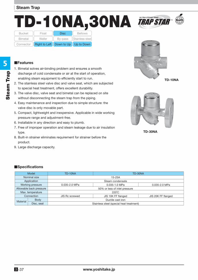
TD-10NA,30NA
TD-10NA
0.035-2.0 MPa
JIS Rc screwed
TD-30NA15-25A
Steam condensate0.035-1.0 MPa
50% or less of inlet pressure220˚C
JIS 10K FF �angedDuctile cast iron
Stainless steel (special heat treatment)
0.035-2.0 MPa
JIS 20K FF �anged
ModelNominal sizeApplication
Working pressureAllowable back pressure
Max. temperatureConnection
Body Disc, seat
Material
TD-10NA
TD-30NA
1. Bimetal solves air-binding problem and ensures a smooth
discharge of cold condensate or air at the start of operation,
enabling steam equipment to efficiently start to run.
2. The stainless steel valve disc and valve seat, which are subjected
to special heat treatment, offers excellent durability.
3. The valve disc, valve seat and bimetal can be replaced on site
without disconnecting the steam trap from the piping.
4. Easy maintenance and inspection due to simple structure: the
valve disc is only movable part.
5. Compact, lightweight and inexpensive. Applicable in wide working
pressure range and adjustment-free.
6. Installable in any direction and easy to plumb.
7. Free of improper operation and steam leakage due to air insulation
type.
8. Built-in strainer eliminates requirement for strainer before the
product.
9. Large discharge capacity.
■Specifications
■Features
5
www.yoshitake.jp 5 -38
Ste
am
Tra
p
TD-10NA, 30NA
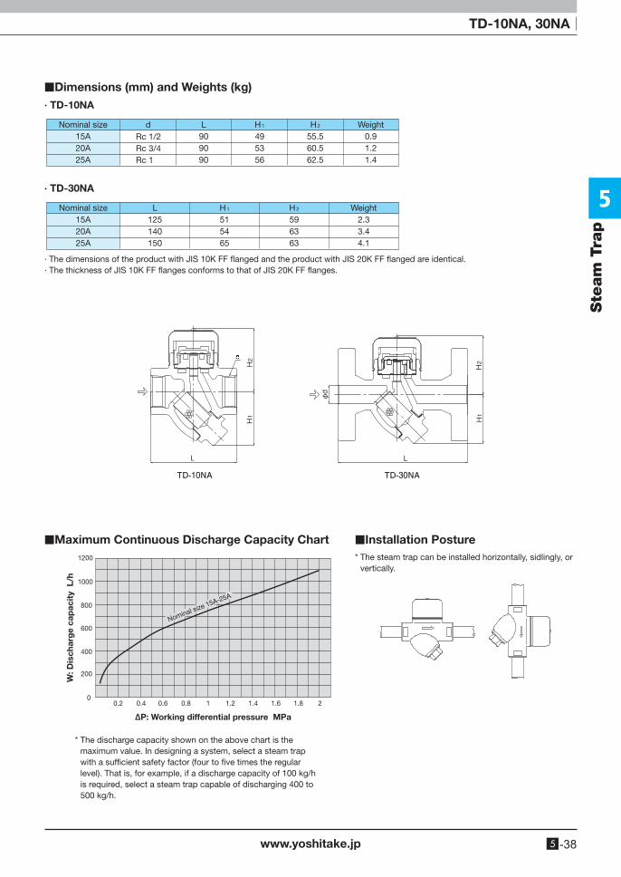
■Dimensions (mm) and Weights (kg)· TD-10NA
Nominal size15A20A25A
Weight0.91.21.4
dRc 1/2Rc 3/4Rc 1
L909090
H1
495356
H2
55.560.562.5
Nominal size15A20A25A
Weight2.33.44.1
L125140150
H1
515465
H2
596363
· TD-30NA
· The dimensions of the product with JIS 10K FF flanged and the product with JIS 20K FF flanged are identical.· The thickness of JIS 10K FF flanges conforms to that of JIS 20K FF flanges.
1200
1000
800
600
400
200
00.2 0.4 0.6 0.8 1 1.2 1.4 1.6 1.8 2
W: D
isch
arg
e ca
pac
ity
L/h
∆P: Working differential pressure MPa
Nominal size 15A-25A
■Maximum Continuous Discharge Capacity Chart ■Installation Posture
* The discharge capacity shown on the above chart is the maximum value. In designing a system, select a steam trap with a sufficient safety factor (four to five times the regular level). That is, for example, if a discharge capacity of 100 kg/h is required, select a steam trap capable of discharging 400 to 500 kg/h.
* The steam trap can be installed horizontally, sidlingly, or vertically.
5
www.yoshitake.jp5 -39
Steam TrapSte
am
Tra
p
Bucket Float Disc Bellows
Wafer By-pass Stainless steelBimetal
Right to Left Down to Up Up to DownConnector
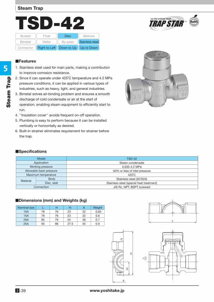
TSD-42
1. Stainless steel used for main parts, making a contribution
to improve corrosion resistance.
2. Since it can operate under 425˚C temperature and 4.2 MPa
pressure conditions, it can be applied in various types of
industries, such as heavy, light, and general industries.
3. Bimetal solves air-binding problem and ensures a smooth
discharge of cold condensate or air at the start of
operation, enabling steam equipment to efficiently start to
run.
4. ''Insulation cover'' avoids frequent on-off operation.
5. Plumbing is easy to perform because it can be installed
vertically or horizontally as desired.
6. Built-in strainer eliminates requirement for strainer before
the trap.
■Specifications
TSD-42Steam condensate
0.035-4.2 MPa50% or less of inlet pressure
425˚CStainless steel (SCS2A)
Stainless steel (special heat treatment)JIS Rc, NPT, BSPT screwed
ModelApplication
Working pressureAllowable back pressureMaximum temperature Body
Disc, seatConnection
Material
■Dimensions (mm) and Weights (kg)
Nominal size H1 WeightH0.650.60.70.9
10A15A20A25A
23232427.5
76767986
32323845
L78788595
A
■Features
5
www.yoshitake.jp 5 -40
Ste
am
Tra
p
TSD-42
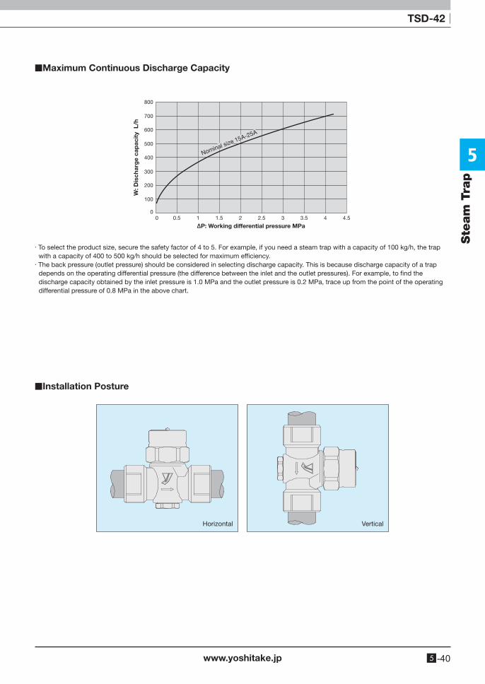
■Maximum Continuous Discharge Capacity
■Installation Posture
· To select the product size, secure the safety factor of 4 to 5. For example, if you need a steam trap with a capacity of 100 kg/h, the trap with a capacity of 400 to 500 kg/h should be selected for maximum efficiency.
· The back pressure (outlet pressure) should be considered in selecting discharge capacity. This is because discharge capacity of a trap depends on the operating differential pressure (the difference between the inlet and the outlet pressures). For example, to find the discharge capacity obtained by the inlet pressure is 1.0 MPa and the outlet pressure is 0.2 MPa, trace up from the point of the operating differential pressure of 0.8 MPa in the above chart.
0
100
200
300
400
500
600
700
800
0.50 1 1.5 2 2.5 3 3.5 4 4.5
W: D
isch
arg
e ca
pac
ity
L/h
∆P: Working differential pressure MPa
Nominal size 15A-25A
Horizontal Vertical