Embed Size (px)
Citation preview
Gillette Generators, Inc. •••• 2921 Thorne Dr. •Elkhart, IN • 46514 • Ph: 574-264-9639 • Fax: 574-262-1840 • Web: www.gillettegenerators.com • spc4-190720 1
60 HZ MODEL
SPMI-8000
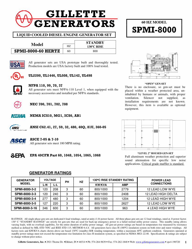
GENERATOR RATINGS
GENERATOR
MODEL
VOLTAGE PH HZ
130°°°°C RISE STANDBY RATING POWER LEAD
CONNECTIONS L-N L-L KW/KVA AMP
SPMI-8000-3-2 120 208 3 60 800/1000 2779 12 LEAD LOW WYE
SPMI-8000-3-3 120 240 3 60 800/1000 2408 12 LEAD HIGH DELTA
SPMI-8000-3-4 277 480 3 60 800/1000 1204 12 LEAD HIGH WYE
SPMI-8000-3-5 127 220 3 60 800/1000 2627 12 LEAD LOW WYE
SPMI-8000-3-16 346 600 3 60 800/1000 963 4 LEAD HIGH WYE
RATINGS: All single phase gen-sets are dedicated 4 lead windings, rated at unity (1.0) power factor. All three phase gen-sets are 12 lead windings, rated at .8 power factor. 130° C “STANDBY RATINGS” are strictly for gen-sets that are used for back-up emergency power to a failed normal utility power source. This standby rating allows varying loads, with no overload capability, for the entire duration of utility power outage. All gen-set power ratings are based on temperature rise measured by resistance method as defined by MIL-STD 705C and IEEE STD 115, METHOD 6.4.4. All generators have class H (180°C) insulation system on both rotor and stator windings. All factory tests and KW/KVA charts shown above are based 130°C (standby) R/R winding temperature, within a maximum 40°C ambient condition. Generators operated at standby power ratings must not exceed the temperature rise limitation for class H insulation system, as specified in NEMA MG1-22.40. Specifications & ratings are subject to change without prior notice.
LIQUID COOLED DIESEL ENGINE GENERATOR SET
Model STANDBY
130ºC RISE HZ
SPMI-8000-60 HERTZ 60 800
All generator sets are USA prototype built and thoroughly tested. Production models are USA factory built and 100% load tested.
UL2200, UL1446, UL508, UL142, UL498
NFPA 110, 99, 70, 37 All generator sets meet NFPA-110 Level 1, when equipped with the necessary accessories and installed per NFPA standards.
NEC 700, 701, 702, 708 NEMA ICS10, MG1, ICS6, AB1 ANSI C62.41, 27, 59, 32, 480, 40Q, 81U, 360-05 ASCE 7-05 & 7-10
All generator sets meet 180 MPH rating. EPA 40CFR Part 60, 1048, 1054, 1065, 1068
“OPEN” GEN-SET
There is no enclosure, so gen-set must be placed within a weather protected area, un-inhabited by humans or animals, with proper ventilation. Silencer not supplied, as installation requirements are not known. However, this item is available as optional equipment.
“LEVEL 2” HOUSED GEN-SET
Full aluminum weather protection and superior sound attenuation for specific low noise applications. Critical grade muffler is standard.
Gillette Generators, Inc. •••• 2921 Thorne Dr. •Elkhart, IN • 46514 • Ph: 574-264-9639 • Fax: 574-262-1840 • Web: www.gillettegenerators.com • spc4-190720 2
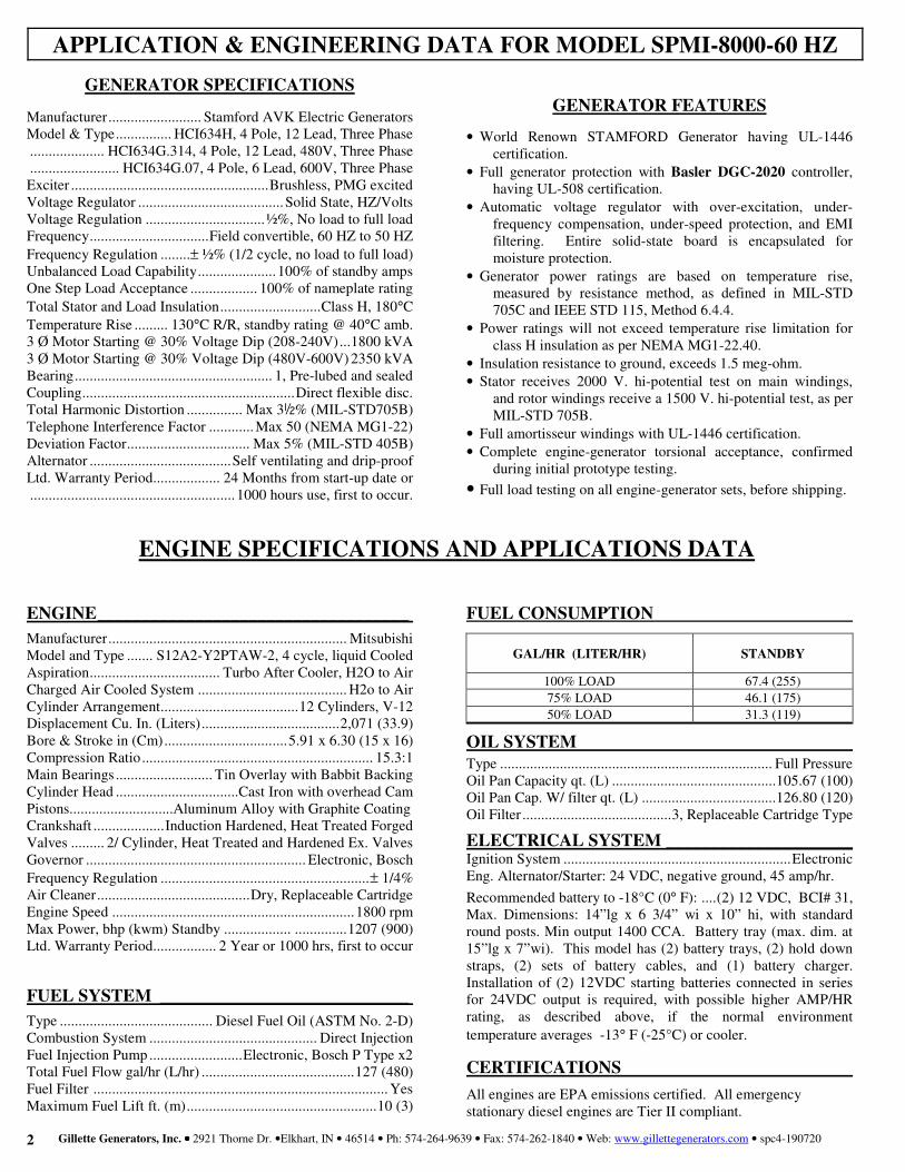
GENERATOR SPECIFICATIONS
Manufacturer ......................... Stamford AVK Electric Generators Model & Type ............... HCI634H, 4 Pole, 12 Lead, Three Phase .................... HCI634G.314, 4 Pole, 12 Lead, 480V, Three Phase ........................ HCI634G.07, 4 Pole, 6 Lead, 600V, Three Phase Exciter ..................................................... Brushless, PMG excited Voltage Regulator ....................................... Solid State, HZ/Volts Voltage Regulation ................................ !%, No load to full load Frequency ................................ Field convertible, 60 HZ to 50 HZ Frequency Regulation ........ ± !% (1/2 cycle, no load to full load) Unbalanced Load Capability ..................... 100% of standby amps One Step Load Acceptance .................. 100% of nameplate rating Total Stator and Load Insulation ........................... Class H, 180°C Temperature Rise ......... 130°C R/R, standby rating @ 40°C amb. 3 Ø Motor Starting @ 30% Voltage Dip (208-240V) ... 1800 kVA 3 Ø Motor Starting @ 30% Voltage Dip (480V-600V) 2350 kVA Bearing ..................................................... 1, Pre-lubed and sealed Coupling ......................................................... Direct flexible disc. Total Harmonic Distortion ............... Max 3½% (MIL-STD705B) Telephone Interference Factor ............ Max 50 (NEMA MG1-22) Deviation Factor ................................. Max 5% (MIL-STD 405B) Alternator ...................................... Self ventilating and drip-proof Ltd. Warranty Period .................. 24 Months from start-up date or ....................................................... 1000 hours use, first to occur.
ENGINE ___________________________________
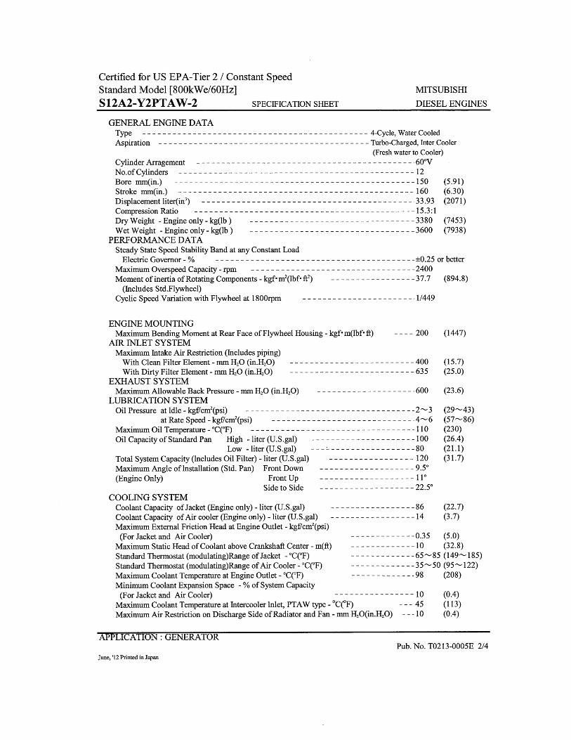
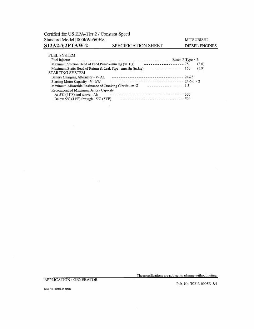
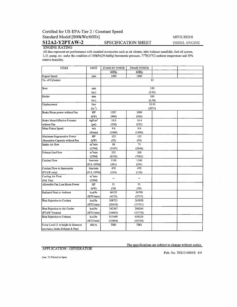
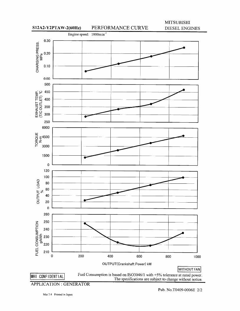
Manufacturer ................................................................ Mitsubishi Model and Type ....... S12A2-Y2PTAW-2, 4 cycle, liquid Cooled Aspiration ................................... Turbo After Cooler, H2O to Air Charged Air Cooled System ........................................ H2o to Air Cylinder Arrangement ..................................... 12 Cylinders, V-12 Displacement Cu. In. (Liters) ..................................... 2,071 (33.9) Bore & Stroke in (Cm) ................................. 5.91 x 6.30 (15 x 16) Compression Ratio .............................................................. 15.3:1 Main Bearings .......................... Tin Overlay with Babbit Backing Cylinder Head .................................Cast Iron with overhead Cam Pistons............................Aluminum Alloy with Graphite Coating Crankshaft ................... Induction Hardened, Heat Treated Forged Valves ......... 2/ Cylinder, Heat Treated and Hardened Ex. Valves Governor ........................................................... Electronic, Bosch Frequency Regulation ........................................................ ± 1/4% Air Cleaner ......................................... Dry, Replaceable Cartridge Engine Speed ................................................................. 1800 rpm Max Power, bhp (kwm) Standby .................. .............. 1207 (900) Ltd. Warranty Period ................. 2 Year or 1000 hrs, first to occur
FUEL SYSTEM ____________________________
Type ......................................... Diesel Fuel Oil (ASTM No. 2-D) Combustion System ............................................. Direct Injection Fuel Injection Pump ......................... Electronic, Bosch P Type x2 Total Fuel Flow gal/hr (L/hr) ......................................... 127 (480) Fuel Filter ............................................................................... Yes Maximum Fuel Lift ft. (m) ................................................... 10 (3)
GENERATOR FEATURES
• World Renown STAMFORD Generator having UL-1446 certification.
• Full generator protection with Basler DGC-2020 controller, having UL-508 certification.
• Automatic voltage regulator with over-excitation, under-frequency compensation, under-speed protection, and EMI filtering. Entire solid-state board is encapsulated for moisture protection.
• Generator power ratings are based on temperature rise, measured by resistance method, as defined in MIL-STD 705C and IEEE STD 115, Method 6.4.4.
• Power ratings will not exceed temperature rise limitation for class H insulation as per NEMA MG1-22.40.
• Insulation resistance to ground, exceeds 1.5 meg-ohm. • Stator receives 2000 V. hi-potential test on main windings,
and rotor windings receive a 1500 V. hi-potential test, as per MIL-STD 705B.
• Full amortisseur windings with UL-1446 certification. • Complete engine-generator torsional acceptance, confirmed
during initial prototype testing.
• Full load testing on all engine-generator sets, before shipping.
FUEL CONSUMPTION
GAL/HR (LITER/HR) STANDBY
100% LOAD 67.4 (255) 75% LOAD 46.1 (175) 50% LOAD 31.3 (119)
OIL SYSTEM
Type ......................................................................... Full Pressure Oil Pan Capacity qt. (L) ............................................ 105.67 (100) Oil Pan Cap. W/ filter qt. (L) .................................... 126.80 (120) Oil Filter ........................................ 3, Replaceable Cartridge Type
ELECTRICAL SYSTEM _____________________ Ignition System ............................................................. Electronic Eng. Alternator/Starter: 24 VDC, negative ground, 45 amp/hr.
Recommended battery to -18°C (0° F): .... (2) 12 VDC, BCI# 31, Max. Dimensions: 14”lg x 6 3/4” wi x 10” hi, with standard round posts. Min output 1400 CCA. Battery tray (max. dim. at 15”lg x 7”wi). This model has (2) battery trays, (2) hold down straps, (2) sets of battery cables, and (1) battery charger. Installation of (2) 12VDC starting batteries connected in series for 24VDC output is required, with possible higher AMP/HR rating, as described above, if the normal environment temperature averages -13° F (-25°C) or cooler.
CERTIFICATIONS
All engines are EPA emissions certified. All emergency stationary diesel engines are Tier II compliant.
APPLICATION & ENGINEERING DATA FOR MODEL SPMI-8000-60 HZ
ENGINE SPECIFICATIONS AND APPLICATIONS DATA
Gillette Generators, Inc. •••• 2921 Thorne Dr. •Elkhart, IN • 46514 • Ph: 574-264-9639 • Fax: 574-262-1840 • Web: www.gillettegenerators.com • spc4-190720 3
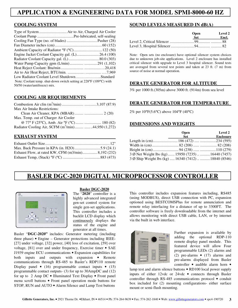
COOLING SYSTEM
Type of System ............................ Air to Air, Charged Air Cooler Coolant Pump ..................................... Pre-lubricated, self-sealing Cooling Fan Type (no. of blades) ............................... Pusher (28) Fan Diameter inches (cm) ................................................ 60 (152) Ambient Capacity of Radiator °F (°C) ............................. 122 (50) Engine Jacket Coolant Capacity gal. (L)....................... 26.4 (100) Radiator Coolant Capacity gal. (L) ............................... 80.0 (303) Water Pump Capacity gpm (L/min) .............. ............. 291 (1,102) Heat Reject Coolant: Btu/min ....................... ................….20,418 Air to Air Heat Reject, BTU/min. ................ . ................ ….7,969 Low Radiator Coolant Level Shutdown………………..Standard Note: Coolant temp. shut-down switch setting at 228°F (109°C) with 50/50 (water/antifreeze) mix.
COOLING AIR REQUIREMENTS
Combustion Air cfm (m3/min) ...................... ............ 3,107 (87.9) Max Air Intake Restrictions: Clean Air Cleaner, KPA (MBAR) ......... ................... 2 (20) Max. Temp. out of Charger Air Cooler @ 77° F (25°C), Amb. Air °F (°C) ........ ................. 180 (82) Radiator Cooling Air, SCFM (m3/min) ......... ...... ..44,950 (1,272)
EXHAUST SYSTEM
Exhaust Outlet Size .................................................................. 12" Max. Back Pressure in KPA (in. H2O) .......................... 5.9 (24.1) Exhaust Flow, at rated KW, CFM (m3/min) ............... 8,192 (232) Exhaust Temp, (Stack) °F (ºC) ..................... ................ 883 (473)
Basler DGC-2020
The “2020” controller is a highly advanced integrated gen-set control system for single gen-set applications. This controller includes a backlit LCD display which continuously displays the status of the engine and generator at all times.
Basler “DGC-2020” includes: Generator metering (including three phase) • Engine – Generator protections including IEEE- [27] under voltage, [32] power, [40] loss of excitation, [59] over voltage, [81] over and under frequency, Exercise timer • SAE J1939 engine ECU communications • Expansion capabilities for both inputs and outputs with expansion • Remote communications through RS-485 to Basler’s RDP110 remote Display panel • (16) programmable contact inputs • (15) programmable contact outputs- (3) for up to 30AmpDC and (12) for up to 2 Amp DC • Illuminated Text Display • Front panel menu scroll buttons • Front panel operation mode buttons for STOP, RUN and AUTO • Alarm Silence and Lamp Test buttons
SOUND LEVELS MEASURED IN dB(A) Open Level 2 Set Encl. Level 2, Critical Silencer ......................... 99............ ........... 88 Level 3, Hospital Silencer ........................ 94............ ........... 82
Note: Open sets (no enclosure) have optional silencer system choices due to unknown job-site applications. Level 2 enclosure has installed critical silencer with upgrade to Level 3 hospital silencer. Sound tests are averaged from several test points and taken at 23 ft. (7 m) from source of noise at normal operation.
DERATE GENERATOR FOR ALTITUDE
3% per 1000 ft.(305m) above 3000 ft. (914m) from sea level
DERATE GENERATOR FOR TEMPERATURE
2% per 10°F(5.6°C) above 104°F (40°C)
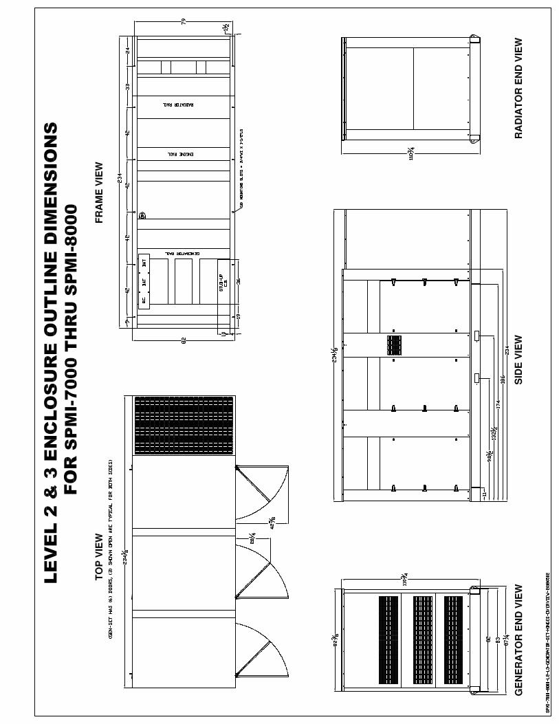
DIMENSIONS AND WEIGHTS Open Level 2 Set Enclosure Length in (cm) ......................... 186 (472) ..... ................ 234 (595) Width in (cm) ........................... 82 (208) ...... ................. 82 (208) Height in (cm) .......................... 94 (238) ...... ................ 110 (279) 3 Ø Net Weight lbs (kg) ....... 15950 (7235) .. .......... 16440 (7457) 3 Ø Ship Weight lbs (kg) ..... 16340 (7412) .. .......... 18840 (8546)
This controller includes expansion features including, RS485 (using MODBUS), direct USB connection with PC, expansion optioned using BESTCOMSPlus for remote annunciation and remote relay interfacing for a distance of up to 3300FT. The controller software is freely downloadable from the internet and allows monitoring with direct USB cable, LAN, or by internet via the built in web interface.
Further expansion is available by adding the optional RDP-110 remote display panel module. This featured device will allow Four programmable LEDs (2) alarms and (2) pre-alarms • (17) alarms and pre-alarms displayed from Basler controller • audible alarm horn •
lamp test and alarm silence buttons • RD100 local power supply inputs of either 12vdc or 24vdc • connects through Basler controller through RS-485 communications protocol • conduit box included for (2) mounting configurations- either surface mount or semi-flush mounting.
APPLICATION & ENGINEERING DATA FOR MODEL SPMI-8000-60 HZ
BASLER DGC-2020 DIGITAL MICROPROCESSOR CONTROLLER

Gillette Generators, Inc. •••• 2921 Thorne Dr. •Elkhart, IN • 46514 • Ph: 574-264-9639 • Fax: 574-262-1840 • Web: www.gillettegenerators.com • spc4-190720 4
CONTROL PANEL:
Basler DGC-2020 digital microprocessor with logic allows programming in the field. Controller has: • STOP-MANUAL-AUTO modes and automatic engine
shutdowns, signaled by full text LCD indicators: • Low oil pressure Engine fail to start • High engine temp Engine over speed Low Radiator Level Engine under speed Three auxiliary alarms Over & under voltage Battery fail alarm
Also included is tamper-proof engine hour meter
ENGINE:
Fuel filter • Full flow Oil filter • Air filter • Fuel pump • Oil pump • Solenoid type starter motor • Hi-temp radiator • Jacket water pump • Thermostat • Pusher fan and guard • Exhaust manifold • Electronic Governor • 24 VDC battery charging alternator • Flexible fuel and exhaust connectors • Vibration isolators • Open coolant recovery system with 50/50 water to anti-freeze mixture • flexible oil & radiator hose • Shut-down sensors for low oil pressure, high coolant temp., low coolant level, high ambient temp.
AC GENERATOR SYSTEM:
AC generator • PMG excited • Brushless design • Circuit Breaker installed and wired to gen-set • Direct connection to engine with flex disc • Class H, 180°C insulation • Self ventilated • Drip proof construction • UL Certified
VOLTAGE REGULATOR:
1% Voltage regulation • EMI filter • Under-speed protection • Over-excitation protection • total encapsulation
DC ELECTRICAL SYSTEM:
Battery tray • Battery cables • Battery hold down straps 3-stage battery charger with float, absorption, & bulk automatic charge stages
WEATHER / SOUNDPROOF ALUMINUM HOUSING: Corrosion Resistant Protection consisting of:
• (9) Heated and Agitated Wash Stages • Zinc Phosphate Etching-Coating Stage • Final Baked on Enamel Powder Coat • 18/8 Stainless Steel Hardware
STANDARD FEATURES FOR MODEL SPMI-8000-60 HZ
STANDARD FEATURES
Design & specifications subject to change without prior notice. Dimensions shown are approximate. Contact Gillette for certified drawings. DO NOT USE DIMENSIONS FOR INSTALLATION PURPOSES.
GENERAL
1-2
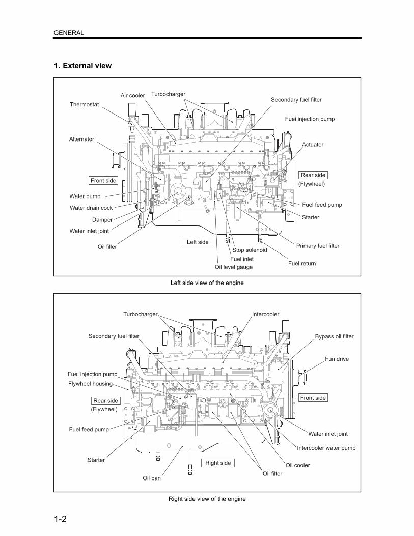
1. External view
Left side view of the engine
Right side view of the engine
Alternator
Water pump
Thermostat
Oil filler
Water drain cock
Water inlet joint
Oil level gauge
Stop solenoid
Fuel inlet
Starter
Primary fuel filter
Fuel return
Fuei injection pump
Actuator
Fuel feed pump
(Flywheel)
Secondary fuel filterAir cooler Turbocharger
Front sideRear side
Left side
Damper
Secondary fuel filter
Fuei injection pump
Fuel feed pump
Starter
(Flywheel)
Front sideRear side
Right side
Water inlet joint
Fun drive
Oil pan
IntercoolerTurbocharger
Oil cooler
Oil filter
Bypass oil filter
Flywheel housing
Intercooler water pump
GENERAL
1-6
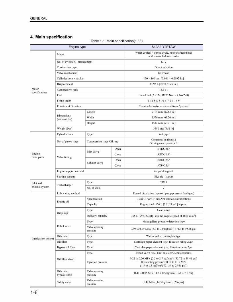
4. Main specificationTable 1-1 Main specification(1 / 3)
Engine type S12A2-Y2PTAW
Majorspecifications
Model Water-cooled, 4-stroke cycle, turbocharged dieselwith air-cooled intercooler
No. of cylinders - arrangement 12-V
Combustion type Direct injection
Valve mechanism Overhead
Cylinder bore × stroke 150 × 160 mm [5.906 × 6.2992 in.]
Displacement 33.93 L [2070.53 cu in.]
Compression ratio 15.3 : 1
Fuel Diesel fuel (ASTM, D975 No.1-D, No.2-D)
Firing order 1-12-5-8-3-10-6-7-2-11-4-9
Rotation of direction Counterclockwise as viewed from flywheel
Dimensions(without fan)
Length 2104 mm [82.83 in.]
Width 1556 mm [61.26 in.]
Height 1542 mm [60.71 in.]
Weight (Dry) 3380 kg [7452 lb]
Enginemain parts
Cylinder liner Type Wet type
No. of piston rings Compression rings Oil ring Compression rings: 2Oil ring (w/expander): 1
Valve timing
Inlet valveOpen BTDC 55°
Close ABDC 65°
Exhaust valveOpen BBDC 65°
Close ATDC 55°
Engine support method 4 - point support
Starting system Electric - starter
Inlet andexhaust system Turbocharger
Type TD10
No. of units 2
Lubrication system
Lubricating method Forced circulation type (oil pump pressure feed type)
Engine oilSpecification Class CD or CF oil (API service classification)
Capacity Engine total: 120 L [32 U.S.gal.] approx.
Oil pumpType Gear pump
Delivery capacity 375 L [99 U.S.gal] / min (at engine speed of 1800 min-1)
Relief valveType Main gallery pressure detection type
Valve openingpressure 0.49 to 0.69 MPa {5.0 to 7.0 kgf/cm²} [71.3 to 99.58 psi]
Oil cooler Type Water-cooled, multi-plate type
Oil filter Type Cartridge paper-element type, filtration rating 20µn
Bypass oil filter Type Cartridge paper-element type, filtration rating 2µn
Oil filter alarm
Type Piston valve type, built-in electric contact points
Injection pressure0.22 to 0.26 MPa {2.3 to 2.7 kgf/cm²} [32.72 to 38.41 psi]
(Contacting pressure: 0.14 to 0.17 MPa{1.5 to 1.8 kgf/cm²} [21.34 to 25.61 psi])
Oil coolerbypass valve
Valve openingpressure 0.44 ± 0.05 MPa {4.5 ± 0.5 kgf/cm²} [64 ± 7.1 psi]
Safety valve Valve openingpressure 1.42 MPa {14.5 kgf/cm²} [206 psi]
GENERAL
1-7
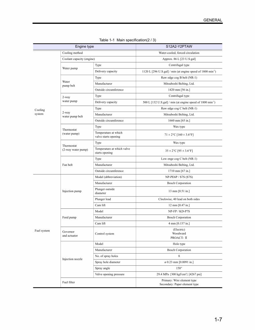
Coolingsystem
Cooling method Water-cooled, forced circulation
Coolant capacity (engine) Approx. 86 L [23 U.S.gal]
Water pumpType Centrifugal type
Delivery capacity 1120 L [296 U.S.gal] / min (at engine speed of 1800 min-1)
Waterpump belt
Type Raw edge cog B belt (NR-1)
Manufacturer Mitsuboshi Belting, Ltd.
Outside circumference 1420 mm [56 in.]
2-waywater pump
Type Centrifugal type
Delivery capacity 500 L [132 U.S.gal] / min (at engine speed of 1800 min-1)
2-waywater pump belt
Type Raw edge cog C belt (NR-1)
Manufacturer Mitsuboshi Belting, Ltd.
Outside circumference 1660 mm [65 in.]
Thermostat(water pump)
Type Wax type
Temperature at whichvalve starts opening 71 ± 2°C [160 ± 3.6°F]
Thermostat(2-way water pump)
Type Wax type
Temperature at which valve starts opening 35 ± 2°C [95 ± 3.6°F]
Fan belt
Type Low enge cog C belt (NR-1)
Manufacturer Mitsuboshi Belting, Ltd.
Outside circumference 1710 mm [67 in.]
Fuel system
Injection pump
Model (abbreviation) NP-PE6P / S7S (S7S)
Manufacturer Bosch Corporation
Plunger outsidediameter 13 mm [0.51 in.]
Plunger lead Clockwise, 40 lead on both sides
Cam lift 12 mm [0.47 in.]
Feed pump
Model NP-FP / KD-P7S
Manufacturer Bosch Corporation
Cam lift 4 mm [0.157 in.]
Governorand actuator Control system
(Electric)Woodward
PROACT- Τ
Injection nozzle
Model Hole type
Manufacturer Bosch Corporation
No. of spray holes 8
Spray hole diameter ø 0.23 mm [0.0091 in.]
Spray angle 158°
Valve opening pressure 29.4 MPa {300 kgf/cm²} [4267 psi]
Fuel filter Primary: Wire element typeSecondary: Paper element type
Table 1-1 Main specification(2 / 3)
Engine type S12A2-Y2PTAW

GENERAL
1-8
Electricalsystem
Voltage - polarity 24 V - Negative (-) ground
Starter
Manufacturer Nikko Electric Industry Co., Ltd.
Piston mesh type Pinion shift
Output 24 V-7.5 kW
No. of units 2
Alternator
Type 3-phase alternating-current generator, built-in IC regulator
Manufacturer Mitsubishi Electric Corporation
Output 24V - 30A
Rated outputgenerating speed Hot 5000 min-1 or less (at 27V, 30A)
Regulated voltage 28.5 ± 0.5V
Magnetic relay(two starters forparallel operation)
Manufacturer Nikko Electric Industry Co., Ltd
Nominal voltage 24V
Rating 30 sec.
Operating voltage 8 to 24V
Operating interval(at 24 V)
1 ON - OFF cycle between SS and SW2.5 to 3.0 sec.
Allowabletemperature -30 to +80°C [-54 to +144°F]
Grounding system 2-wire system
Alternator belt
Type Low edge cog B belt (NR-1)
Manufacturer Mitsuboshi belting, Ltd.
Outside circumference 830 mm [33 in.]
Table 1-1 Main specification(3 / 3)
Engine type S12A2-Y2PTAW
Technical Data Sheet
HCI634H - Winding 311 and 312

HCI634HSPECIFICATIONS & OPTIONS
WINDING 311 and 312
STANDARDS
Stamford industrial generators meet the requirements ofBS EN 60034 and the relevant section of otherinternational standards such as BS5000, VDE 0530,NEMA MG1-32, IEC34, CSA C22.2-100, AS1359.Other standards and certifications can be considered onrequest.
VOLTAGE REGULATORS
MX321 AVR - STANDARD
This sophisticated Automatic Voltage Regulator (AVR) isincorporated into the Stamford Permanent MagnetGenerator (PMG) system and is fitted as standard togenerators of this type.The PMG provides power via the AVR to the main exciter,giving a source of constant excitation power independentof generator output. The main exciter output is then fed tothe main rotor, through a full wave bridge, protected by asurge suppressor. The AVR has in-built protectionagainst sustained over-excitation, caused by internal orexternal faults. This de-excites the machine after aminimum of 5 seconds.Over voltage protection is built-in and short circuit currentlevel adjustments is an optional facility.
WINDINGS & ELECTRICAL PERFORMANCE
SHAFT & KEYS
All generator rotors are dynamically balanced tobetter than BS6861:Part 1 Grade 2.5 for minimumvibration in operation. Two bearing generators arebalanced with a half key.
INSULATION/IMPREGNATION
The insulation system is class 'H'.All wound components are impregnated withmaterials and processes designed specifically toprovide the high build required for static windings andthe high mechanical strength required for rotatingcomponents.
QUALITY ASSURANCE
Generators are manufactured using productionprocedures having a quality assurance level to BSEN ISO 9001.
The stated voltage regulation may not be maintainedin the presence of certain radio transmitted signals.Any change in performance will fall within the limits ofCriteria 'B' of EN 61000-6-2:2001. At no time will thesteady-state voltage regulation exceed 2%.
STANDARDS
Stamford industrial generators meet the requirements ofBS EN 60034 and the relevant section of otherinternational standards such as BS5000, VDE 0530,NEMA MG1-32, IEC34, CSA C22.2-100, AS1359.Other standards and certifications can be considered onrequest.
VOLTAGE REGULATORS
MX321 AVR - STANDARD
This sophisticated Automatic Voltage Regulator (AVR) isincorporated into the Stamford Permanent MagnetGenerator (PMG) system and is fitted as standard togenerators of this type.The PMG provides power via the AVR to the main exciter,giving a source of constant excitation power independentof generator output. The main exciter output is then fed tothe main rotor, through a full wave bridge, protected by asurge suppressor. The AVR has in-built protectionagainst sustained over-excitation, caused by internal orexternal faults. This de-excites the machine after aminimum of 5 seconds.Over voltage protection is built-in and short circuit currentlevel adjustments is an optional facility.
WINDINGS & ELECTRICAL PERFORMANCE
All generator stators are wound to 2/3 pitch. Thiseliminates triplen (3rd, 9th, 15th …) harmonics on thevoltage waveform and is found to be the optimum designfor trouble-free supply of non-linear loads. The 2/3 pitchdesign avoids excessive neutral currents sometimes seenwith higher winding pitches, when in parallel with themains. A fully connected damper winding reducesoscillations during paralleling. This winding, with the 2/3pitch and carefully selected pole and tooth designs,ensures very low waveform distortion.
TERMINALS & TERMINAL BOX
Standard generators feature a main stator with either 6ends (Winding 312) or 12 ends (Winding 311) brought outto the terminals, which are mounted on the frame at thenon-drive end of the generator. A sheet steel terminal boxcontains the AVR and provides ample space for thecustomers' wiring and gland arrangements. It hasremovable panels for easy access.
SHAFT & KEYS
All generator rotors are dynamically balanced tobetter than BS6861:Part 1 Grade 2.5 for minimumvibration in operation. Two bearing generators arebalanced with a half key.
INSULATION/IMPREGNATION
The insulation system is class 'H'.All wound components are impregnated withmaterials and processes designed specifically toprovide the high build required for static windings andthe high mechanical strength required for rotatingcomponents.
QUALITY ASSURANCE
Generators are manufactured using productionprocedures having a quality assurance level to BSEN ISO 9001.
The stated voltage regulation may not be maintainedin the presence of certain radio transmitted signals.Any change in performance will fall within the limits ofCriteria 'B' of EN 61000-6-2:2001. At no time will thesteady-state voltage regulation exceed 2%.
DE RATES
All values tabulated on page 8 are subject to thefollowing reductions
5% when air inlet filters are fitted.10% when IP44 Filters are fitted.3% for every 500 metres by which the operatingaltitude exceeds 1000 metres above mean sea level.3% for every 5 C by which the operational ambienttemperature exceeds 40 C.
Note: Requirement for operating in an ambientexceeding 60 C must be referred to the factory.
NB Continuous development of our products entitlesus to change specification details without notice,therefore they must not be regarded as binding.
Front cover drawing typical of product range.
2
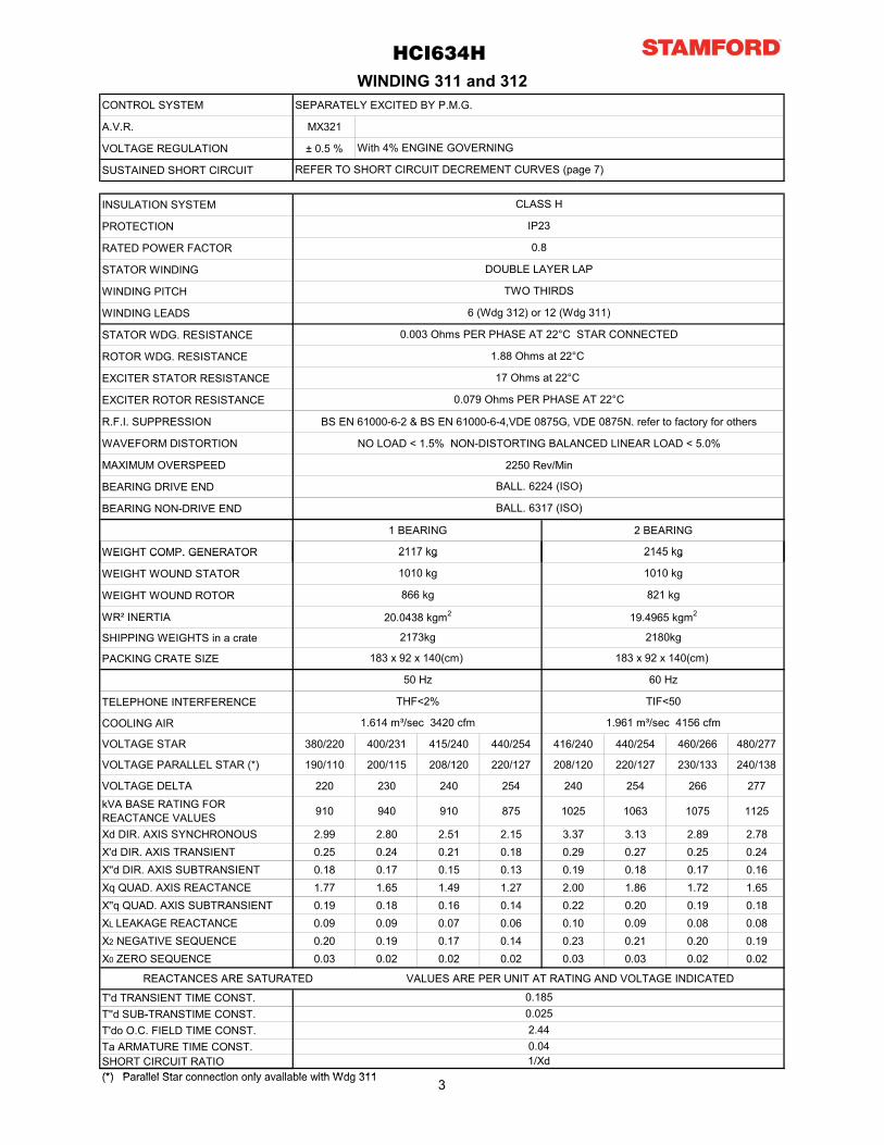
CONTROL SYSTEM SEPARATELY EXCITED BY P.M.G.
A.V.R. MX321
VOLTAGE REGULATION ± 0.5 %
SUSTAINED SHORT CIRCUIT
INSULATION SYSTEM
PROTECTION
RATED POWER FACTOR
STATOR WINDING
WINDING PITCH
WINDING LEADS
STATOR WDG. RESISTANCE
ROTOR WDG. RESISTANCE
EXCITER STATOR RESISTANCE
EXCITER ROTOR RESISTANCE
R.F.I. SUPPRESSION BS EN 61000-6-2 & BS EN 61000-6-4,VDE 0875G, VDE 0875N. refer to factory for others
WAVEFORM DISTORTION NO LOAD < 1.5% NON-DISTORTING BALANCED LINEAR LOAD < 5.0%
MAXIMUM OVERSPEED 2250 Rev/Min
BEARING DRIVE END
BEARING NON-DRIVE END
1 BEARING 2 BEARING
WEIGHT COMP. GENERATOR
DOUBLE LAYER LAP
1.88 Ohms at 22°C
0.003 Ohms PER PHASE AT 22°C STAR CONNECTED
6 (Wdg 312) or 12 (Wdg 311)
TWO THIRDS
2117 kg
BALL. 6224 (ISO)
REFER TO SHORT CIRCUIT DECREMENT CURVES (page 7)
WINDING 311 and 312
With 4% ENGINE GOVERNING
0.8
IP23
CLASS H
BALL. 6317 (ISO)
17 Ohms at 22°C
0.079 Ohms PER PHASE AT 22°C
HCI634H
2145 kgWEIGHT COMP. GENERATOR
WEIGHT WOUND STATOR
WEIGHT WOUND ROTOR
WR² INERTIA
SHIPPING WEIGHTS in a crate
PACKING CRATE SIZE
TELEPHONE INTERFERENCE
COOLING AIR
VOLTAGE STAR 380/220 400/231 415/240 440/254 416/240 440/254 460/266 480/277
VOLTAGE PARALLEL STAR (*) 190/110 200/115 208/120 220/127 208/120 220/127 230/133 240/138
VOLTAGE DELTA 220 230 240 254 240 254 266 277kVA BASE RATING FOR REACTANCE VALUES 910 940 910 875 1025 1063 1075 1125
Xd DIR. AXIS SYNCHRONOUS 2.99 2.80 2.51 2.15 3.37 3.13 2.89 2.78X'd DIR. AXIS TRANSIENT 0.25 0.24 0.21 0.18 0.29 0.27 0.25 0.24X''d DIR. AXIS SUBTRANSIENT 0.18 0.17 0.15 0.13 0.19 0.18 0.17 0.16Xq QUAD. AXIS REACTANCE 1.77 1.65 1.49 1.27 2.00 1.86 1.72 1.65X''q QUAD. AXIS SUBTRANSIENT 0.19 0.18 0.16 0.14 0.22 0.20 0.19 0.18XL LEAKAGE REACTANCE 0.09 0.09 0.07 0.06 0.10 0.09 0.08 0.08X2 NEGATIVE SEQUENCE 0.20 0.19 0.17 0.14 0.23 0.21 0.20 0.19X0 ZERO SEQUENCE 0.03 0.02 0.02 0.02 0.03 0.03 0.02 0.02
REACTANCES ARE SATURATED VALUES ARE PER UNIT AT RATING AND VOLTAGE INDICATED
T'd TRANSIENT TIME CONST.T''d SUB-TRANSTIME CONST.T'do O.C. FIELD TIME CONST.Ta ARMATURE TIME CONST.SHORT CIRCUIT RATIO(*) Parallel Star connection only available with Wdg 311
20.0438 kgm2
2180kg
821 kg
1/Xd
1010 kg
2117 kg
1010 kg
1.614 m³/sec 3420 cfm 1.961 m³/sec 4156 cfm
50 Hz
THF<2%
60 Hz
TIF<50
0.04
2145 kg
183 x 92 x 140(cm)
2173kg
0.1850.0252.44
866 kg
19.4965 kgm2
183 x 92 x 140(cm)
(*) Parallel Star connection only available with Wdg 311 3
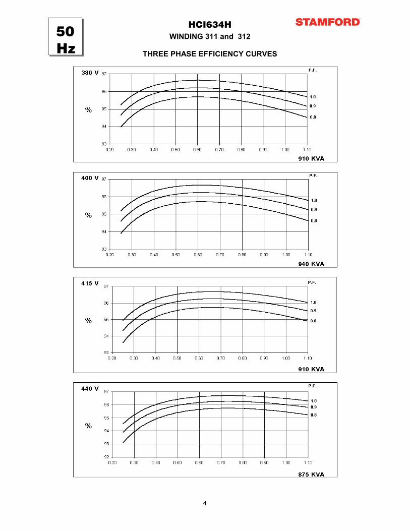
WINDING 311 and 312HCI634H
THREE PHASE EFFICIENCY CURVES
50Hz50Hz
4

WINDING 311 and 312HCI634H
THREE PHASE EFFICIENCY CURVES
60Hz60Hz
5
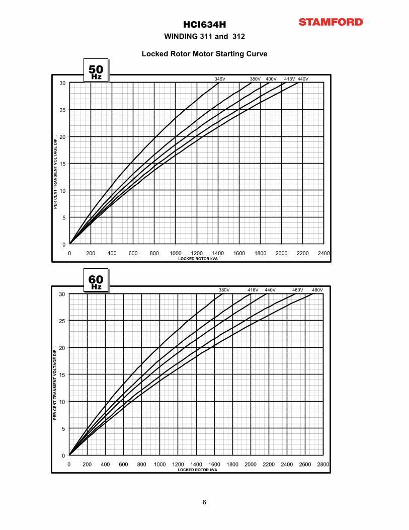
HCI634HWINDING 311 and 312
Locked Rotor Motor Starting Curve
0
5
10
15
20
25
30
0 200 400 600 800 1000 1200 1400 1600 1800 2000 2200 2400LOCKED ROTOR kVA
PER
CEN
T TR
AN
SIEN
T VO
LTA
GE
DIP
.
346V 380V 400V 415V 440V 50Hz
0
5
10
15
20
25
30
0 200 400 600 800 1000 1200 1400 1600 1800 2000 2200 2400LOCKED ROTOR kVA
PER
CEN
T TR
AN
SIEN
T VO
LTA
GE
DIP
.
346V 380V 400V 415V 440V
0
5
10
15
20
25
30
0 200 400 600 800 1000 1200 1400 1600 1800 2000 2200 2400 2600 2800LOCKED ROTOR kVA
PER
CEN
T TR
AN
SIEN
T VO
LTA
GE
DIP
.
380V 416V 440V 460V 480V
50Hz
60Hz
6
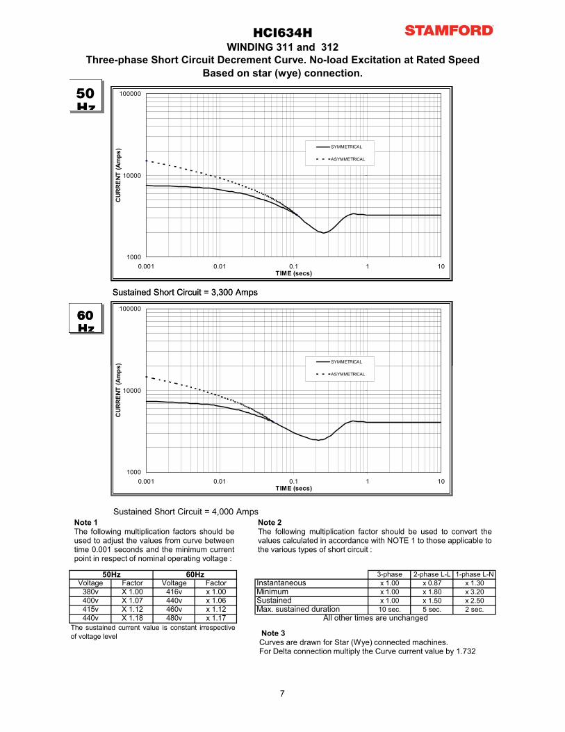
WINDING 311 and 312HCI634H
Three-phase Short Circuit Decrement Curve. No-load Excitation at Rated SpeedBased on star (wye) connection.
Sustained Short Circuit = 3,300 Amps
50Hz
60Hz
1000
10000
100000
0.001 0.01 0.1 1 10TIME (secs)
CUR
RENT
(Am
ps) SYMMETRICAL
ASYMMETRICAL
100000
) SYMMETRICAL
3-phase 2-phase L-L 1-phase L-NVoltage Factor Voltage Factor x 1.00 x 0.87 x 1.30
380v X 1.00 416v x 1.00 x 1.00 x 1.80 x 3.20400v X 1.07 440v x 1.06 x 1.00 x 1.50 x 2.50415v X 1.12 460v x 1.12 10 sec. 5 sec. 2 sec.440v X 1.18 480v x 1.17
SustainedMinimum
50Hz 60Hz
The sustained current value is constant irrespectiveof voltage level
Max. sustained durationAll other times are unchanged
Instantaneous
Sustained Short Circuit = 3,300 Amps
Sustained Short Circuit = 4,000 AmpsNote 1The following multiplication factors should beused to adjust the values from curve betweentime 0.001 seconds and the minimum currentpoint in respect of nominal operating voltage :
Note 2The following multiplication factor should be used to convert thevalues calculated in accordance with NOTE 1 to those applicable tothe various types of short circuit :
50Hz
60Hz
1000
10000
100000
0.001 0.01 0.1 1 10TIME (secs)
CUR
RENT
(Am
ps) SYMMETRICAL
ASYMMETRICAL
1000
10000
100000
0.001 0.01 0.1 1 10TIME (secs)
CUR
RENT
(Am
ps) SYMMETRICAL
ASYMMETRICAL
Note 3Curves are drawn for Star (Wye) connected machines.For Delta connection multiply the Curve current value by 1.732
7
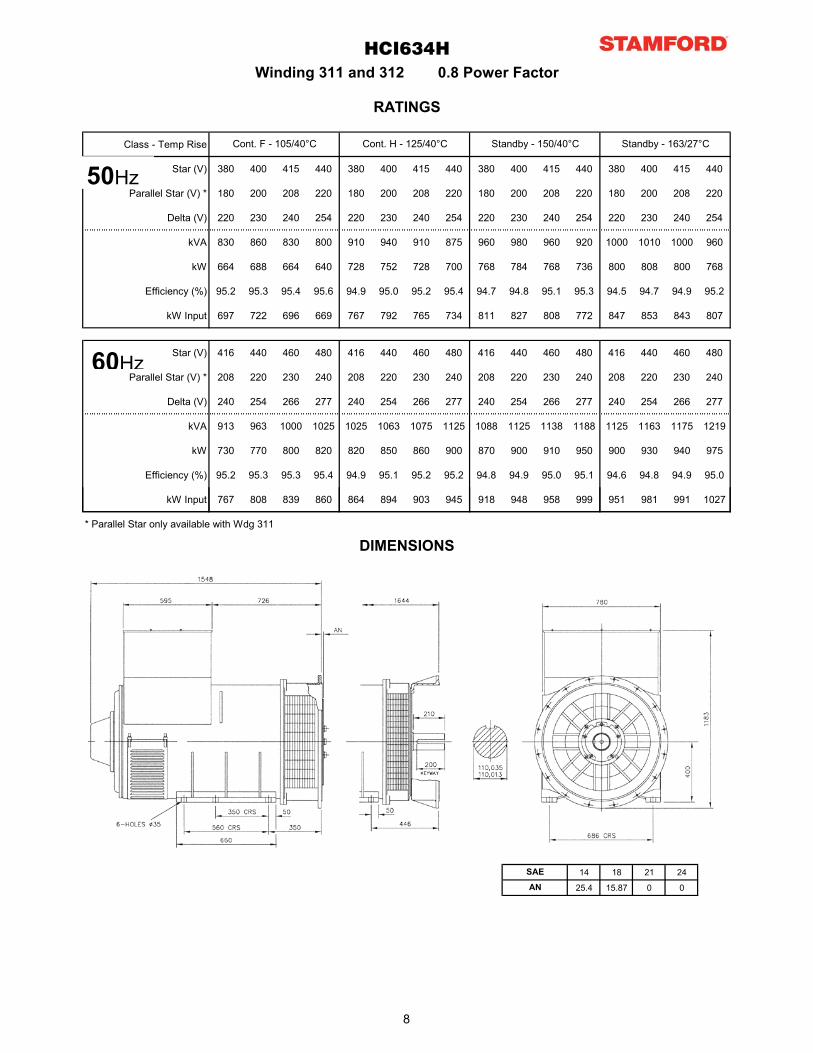
Class - Temp Rise
Star (V) 380 400 415 440 380 400 415 440 380 400 415 440 380 400 415 440
Parallel Star (V) * 180 200 208 220 180 200 208 220 180 200 208 220 180 200 208 220
Delta (V) 220 230 240 254 220 230 240 254 220 230 240 254 220 230 240 254
kVA 830 860 830 800 910 940 910 875 960 980 960 920 1000 1010 1000 960
kW 664 688 664 640 728 752 728 700 768 784 768 736 800 808 800 768
Efficiency (%) 95.2 95.3 95.4 95.6 94.9 95.0 95.2 95.4 94.7 94.8 95.1 95.3 94.5 94.7 94.9 95.2
kW Input 697 722 696 669 767 792 765 734 811 827 808 772 847 853 843 807
Star (V) 416 440 460 480 416 440 460 480 416 440 460 480 416 440 460 480
Parallel Star (V) * 208 220 230 240 208 220 230 240 208 220 230 240 208 220 230 240
Delta (V) 240 254 266 277 240 254 266 277 240 254 266 277 240 254 266 277
kVA 913 963 1000 1025 1025 1063 1075 1125 1088 1125 1138 1188 1125 1163 1175 1219
kW 730 770 800 820 820 850 860 900 870 900 910 950 900 930 940 975
Efficiency (%) 95.2 95.3 95.3 95.4 94.9 95.1 95.2 95.2 94.8 94.9 95.0 95.1 94.6 94.8 94.9 95.0
kW Input 767 808 839 860 864 894 903 945 918 948 958 999 951 981 991 1027
HCI634H
Cont. F - 105/40°C Cont. H - 125/40°C Standby - 150/40°C Standby - 163/27°C
Winding 311 and 312 0.8 Power Factor
RATINGS
50Hz
60Hz
* Parallel Star only available with Wdg 311
14 18 21 24
25.4 15.87 0 0
SAE
AN
DIMENSIONS
50Hz
60Hz
50Hz
60Hz
8

HCI6H-311-312-TD-EN-Rev B
Head Office Address:Barnack Road, StamfordLincolnshire, PE9 2NB
United KingdomTel: +44 (0) 1780 484000Fax: +44 (0) 1780 484100
www.cumminsgeneratortechnologies.com
Copyright 2010, Cummins Generator Technologies Ltd, All Rights ReservedStamford and AvK are registered trade marks of Cummins Generator Technologies Ltd
Cummins and the Cummins logo are registered trade marks of Cummins Inc.
HCI6H-311-312-TD-EN-Rev_B
Head Office Address:Barnack Road, StamfordLincolnshire, PE9 2NB
United KingdomTel: +44 (0) 1780 484000Fax: +44 (0) 1780 484100
www.cumminsgeneratortechnologies.com
Copyright 2010, Cummins Generator Technologies Ltd, All Rights ReservedStamford and AvK are registered trade marks of Cummins Generator Technologies Ltd
Cummins and the Cummins logo are registered trade marks of Cummins Inc.
APPRO
VED D
OC
UM
ENT
Technical Data Sheet
HCI634G - Winding 311 and 312
APPRO
VED D
OC
UM
ENT
HCI634GSPECIFICATIONS & OPTIONS
WINDING 311 and 312
STANDARDS
Stamford industrial generators meet the requirements ofBS EN 60034 and the relevant section of otherinternational standards such as BS5000, VDE 0530,NEMA MG1-32, IEC34, CSA C22.2-100, AS1359.Other standards and certifications can be considered onrequest.
VOLTAGE REGULATORS
MX321 AVR - STANDARD
This sophisticated Automatic Voltage Regulator (AVR) isincorporated into the Stamford Permanent MagnetGenerator (PMG) system and is fitted as standard togenerators of this type.The PMG provides power via the AVR to the main exciter,giving a source of constant excitation power independentof generator output. The main exciter output is then fedto the main rotor, through a full wave bridge, protected bya surge suppressor. The AVR has in-built protectionagainst sustained over-excitation, caused by internal orexternal faults. This de-excites the machine after aminimum of 5 seconds.Over voltage protection is built-in and short circuit currentlevel adjustments is an optional facility.
WINDINGS & ELECTRICAL PERFORMANCE
All generator stators are wound to 2/3 pitch. Thiseliminates triplen (3rd, 9th, 15th …) harmonics on thevoltage waveform and is found to be the optimum designfor trouble-free supply of non-linear loads. The 2/3 pitchdesign avoids excessive neutral currents sometimes seenwith higher winding pitches, when in parallel with themains. A fully connected damper winding reducesoscillations during paralleling. This winding, with the 2/3pitch and carefully selected pole and tooth designs,ensures very low waveform distortion.
TERMINALS & TERMINAL BOX
Standard generators feature a main stator with either 6ends (Winding 312) or 12 ends (Winding 311) brought outto the terminals, which are mounted on the frame at thenon-drive end of the generator. A sheet steel terminalbox contains the AVR and provides ample space for thecustomers' wiring and gland arrangements. It hasremovable panels for easy access.
SHAFT & KEYS
All generator rotors are dynamically balanced tobetter than BS6861:Part 1 Grade 2.5 for minimumvibration in operation. Two bearing generators arebalanced with a half key.
INSULATION/IMPREGNATION
The insulation system is class 'H'.All wound components are impregnated withmaterials and processes designed specifically toprovide the high build required for static windingsand the high mechanical strength required forrotating components.
QUALITY ASSURANCE
Generators are manufactured using productionprocedures having a quality assurance level to BSEN ISO 9001.
The stated voltage regulation may not be maintainedin the presence of certain radio transmitted signals.Any change in performance will fall within the limitsof Criteria 'B' of EN 61000-6-2:2001. At no time willthe steady-state voltage regulation exceed 2%.
DE RATES
All values tabulated on page 8 are subject to thefollowing reductions
5% when air inlet filters are fitted.10% when IP44 Filters are fitted.3% for every 500 metres by which the operatingaltitude exceeds 1000 metres above mean sea level.3% for every 5°C by which the operational ambienttemperature exceeds 40°C.
Note: Requirement for operating in an ambientexceeding 60°C must be referred to the factory.
NB Continuous development of our productsentitles us to change specification details withoutnotice, therefore they must not be regarded asbinding.
Front cover drawing typical of product range.
2
APPRO
VED D
OC
UM
ENT
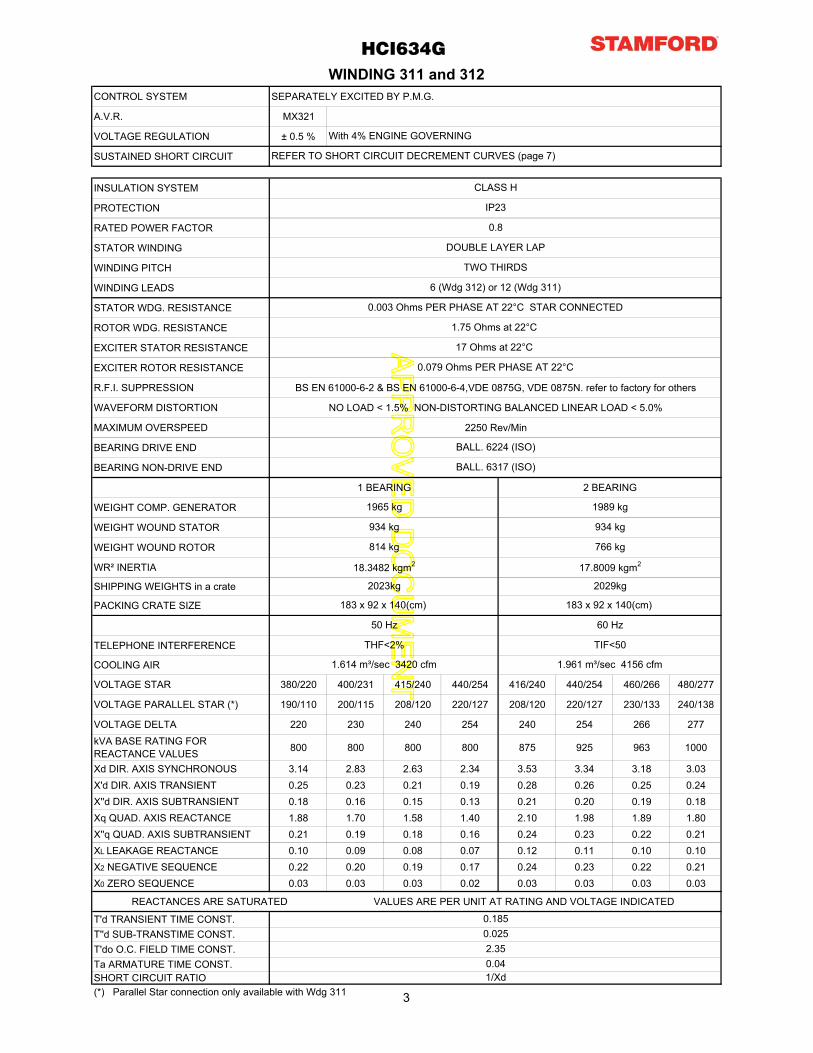
CONTROL SYSTEM SEPARATELY EXCITED BY P.M.G.
A.V.R. MX321
VOLTAGE REGULATION ± 0.5 %
SUSTAINED SHORT CIRCUIT
INSULATION SYSTEM
PROTECTION
RATED POWER FACTOR
STATOR WINDING
WINDING PITCH
WINDING LEADS
STATOR WDG. RESISTANCE
ROTOR WDG. RESISTANCE
EXCITER STATOR RESISTANCE
EXCITER ROTOR RESISTANCE
R.F.I. SUPPRESSION BS EN 61000-6-2 & BS EN 61000-6-4,VDE 0875G, VDE 0875N. refer to factory for others
WAVEFORM DISTORTION NO LOAD < 1.5% NON-DISTORTING BALANCED LINEAR LOAD < 5.0%
MAXIMUM OVERSPEED 2250 Rev/Min
BEARING DRIVE END
BEARING NON-DRIVE END
1 BEARING 2 BEARING
WEIGHT COMP. GENERATOR
WEIGHT WOUND STATOR
WEIGHT WOUND ROTOR
WR² INERTIA
SHIPPING WEIGHTS in a crate
PACKING CRATE SIZE
TELEPHONE INTERFERENCE
COOLING AIR
VOLTAGE STAR 380/220 400/231 415/240 440/254 416/240 440/254 460/266 480/277
VOLTAGE PARALLEL STAR (*) 190/110 200/115 208/120 220/127 208/120 220/127 230/133 240/138
VOLTAGE DELTA 220 230 240 254 240 254 266 277kVA BASE RATING FOR REACTANCE VALUES 800 800 800 800 875 925 963 1000
Xd DIR. AXIS SYNCHRONOUS 3.14 2.83 2.63 2.34 3.53 3.34 3.18 3.03X'd DIR. AXIS TRANSIENT 0.25 0.23 0.21 0.19 0.28 0.26 0.25 0.24X''d DIR. AXIS SUBTRANSIENT 0.18 0.16 0.15 0.13 0.21 0.20 0.19 0.18Xq QUAD. AXIS REACTANCE 1.88 1.70 1.58 1.40 2.10 1.98 1.89 1.80X''q QUAD. AXIS SUBTRANSIENT 0.21 0.19 0.18 0.16 0.24 0.23 0.22 0.21XL LEAKAGE REACTANCE 0.10 0.09 0.08 0.07 0.12 0.11 0.10 0.10X2 NEGATIVE SEQUENCE 0.22 0.20 0.19 0.17 0.24 0.23 0.22 0.21X0 ZERO SEQUENCE 0.03 0.03 0.03 0.02 0.03 0.03 0.03 0.03
REACTANCES ARE SATURATED VALUES ARE PER UNIT AT RATING AND VOLTAGE INDICATED
T'd TRANSIENT TIME CONST.T''d SUB-TRANSTIME CONST.T'do O.C. FIELD TIME CONST.Ta ARMATURE TIME CONST.SHORT CIRCUIT RATIO(*) Parallel Star connection only available with Wdg 311
0.1850.0252.350.04
HCI634G
1.614 m³/sec 3420 cfm 1.961 m³/sec 4156 cfm
50 Hz
THF<2%
60 Hz
TIF<50
1989 kg
183 x 92 x 140(cm)
2023kg
0.8
IP23
CLASS H
BALL. 6317 (ISO)
17 Ohms at 22°C
0.079 Ohms PER PHASE AT 22°C
REFER TO SHORT CIRCUIT DECREMENT CURVES (page 7)
WINDING 311 and 312
With 4% ENGINE GOVERNING
1/Xd
DOUBLE LAYER LAP
1.75 Ohms at 22°C
0.003 Ohms PER PHASE AT 22°C STAR CONNECTED
6 (Wdg 312) or 12 (Wdg 311)
TWO THIRDS
934 kg
1965 kg
934 kg
BALL. 6224 (ISO)
814 kg
17.8009 kgm2
183 x 92 x 140(cm)
18.3482 kgm2
2029kg
766 kg
3
APPRO
VED D
OC
UM
ENT
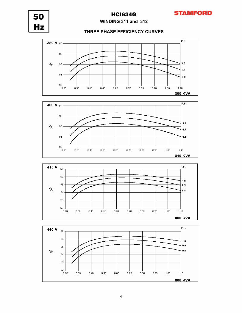
WINDING 311 and 312HCI634G
THREE PHASE EFFICIENCY CURVES
50Hz
4
APPRO
VED D
OC
UM
ENT
WINDING 311 and 312HCI634G
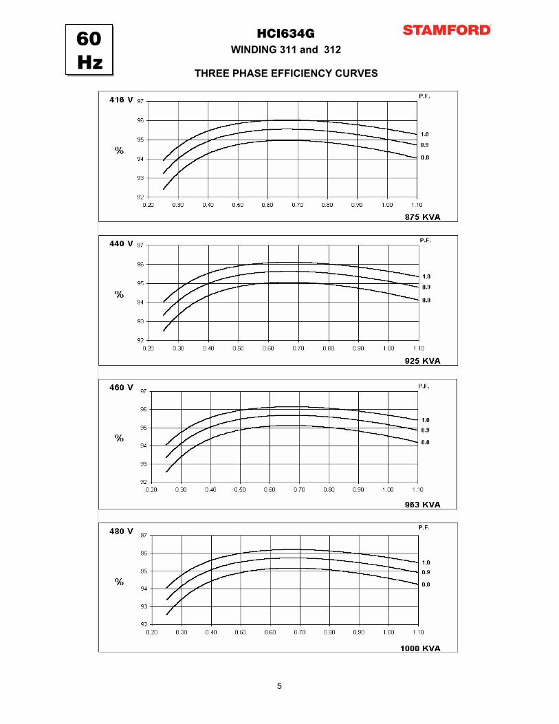
THREE PHASE EFFICIENCY CURVES
60Hz
5
APPRO
VED D
OC
UM
ENT
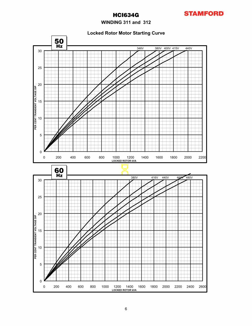
HCI634GWINDING 311 and 312
Locked Rotor Motor Starting Curve
0
5
10
15
20
25
30
0 200 400 600 800 1000 1200 1400 1600 1800 2000 2200LOCKED ROTOR kVA
PER
CEN
T TR
AN
SIEN
T VO
LTA
GE
DIP
.
346V 380V 400V 415V 440V
0
5
10
15
20
25
30
0 200 400 600 800 1000 1200 1400 1600 1800 2000 2200 2400 2600LOCKED ROTOR kVA
PER
CEN
T TR
AN
SIEN
T VO
LTA
GE
DIP
.
380V 416V 440V 460V 480V
60Hz
50Hz
6
APPRO
VED D
OC
UM
ENT
3-phase 2-phase L-L 1-phase L-NVoltage Factor Voltage Factor x 1.00 x 0.87 x 1.30
380v X 1.00 416v x 1.00 x 1.00 x 1.80 x 3.20400v X 1.07 440v x 1.06 x 1.00 x 1.50 x 2.50415v X 1.12 460v x 1.12 10 sec. 5 sec. 2 sec.440v X 1.18 480v x 1.17
The sustained current value is constant irrespectiveof voltage level
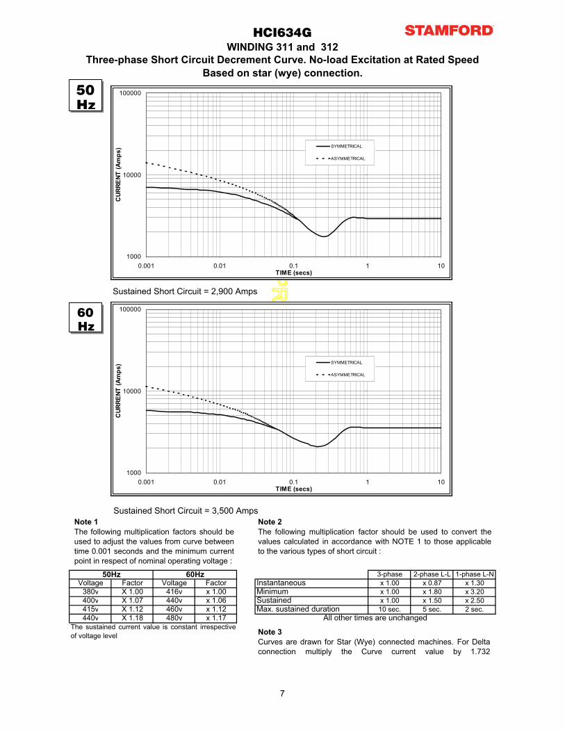
Three-phase Short Circuit Decrement Curve. No-load Excitation at Rated SpeedBased on star (wye) connection.
Max. sustained durationAll other times are unchanged
Instantaneous
SustainedMinimum
WINDING 311 and 312HCI634G
50Hz 60Hz
Sustained Short Circuit = 2,900 Amps
Sustained Short Circuit = 3,500 AmpsNote 1The following multiplication factors should beused to adjust the values from curve betweentime 0.001 seconds and the minimum currentpoint in respect of nominal operating voltage :
Note 2The following multiplication factor should be used to convert thevalues calculated in accordance with NOTE 1 to those applicableto the various types of short circuit :
Note 3Curves are drawn for Star (Wye) connected machines. For Deltaconnection multiply the Curve current value by 1.732
50Hz
60Hz
1000
10000
100000
0.001 0.01 0.1 1 10TIME (secs)
CUR
RENT
(Am
ps) SYMMETRICAL
ASYMMETRICAL
1000
10000
100000
0.001 0.01 0.1 1 10TIME (secs)
CUR
RENT
(Am
ps) SYMMETRICAL
ASYMMETRICAL
7

APPRO
VED D
OC
UM
ENT
Class - Temp Rise
Star (V) 380 400 415 440 380 400 415 440 380 400 415 440 380 400 415 440
Parallel Star (V) * 180 200 208 220 180 200 208 220 180 200 208 220 180 200 208 220
Delta (V) 220 230 240 254 220 230 240 254 220 230 240 254 220 230 240 254
kVA 750 760 750 750 800 810 800 800 825 830 825 820 850 860 850 850
kW 600 608 600 600 640 648 640 640 660 664 660 656 680 688 680 680
Efficiency (%) 94.5 94.6 94.8 95.0 94.2 94.4 94.6 94.8 94.1 94.3 94.5 94.7 93.9 94.2 94.4 94.6
kW Input 635 643 633 632 679 686 677 675 702 704 698 693 724 730 720 719
Star (V) 416 440 460 480 416 440 460 480 416 440 460 480 416 440 460 480
Parallel Star (V) * 208 220 230 240 208 220 230 240 208 220 230 240 208 220 230 240
Delta (V) 240 254 266 277 240 254 266 277 240 254 266 277 240 254 266 277
kVA 813 844 888 913 875 925 963 1000 913 969 1008 1046 950 1000 1044 1088
kW 650 675 710 730 700 740 770 800 730 775 806 837 760 800 835 870
Efficiency (%) 94.6 94.7 94.8 94.8 94.4 94.5 94.5 94.6 94.2 94.3 94.4 94.4 94.1 94.2 94.3 94.3
kW Input 688 713 749 770 742 783 815 846 775 822 854 886 808 849 886 923
* Parallel Star only available with Wdg 311
14 18 21 24
25.4 15.87 0 0
HCI634G
Cont. F - 105/40°C Cont. H - 125/40°C Standby - 150/40°C Standby - 163/27°C
Winding 311 and 312 0.8 Power Factor
RATINGS
SAE
AN
DIMENSIONS
50Hz
60Hz
8

APPRO
VED D
OC
UM
ENT
HCI6G-311-312-TD-EN-SG-A
Head Office Address:Barnack Road, StamfordLincolnshire, PE9 2NB
United KingdomTel: +44 (0) 1780 484000Fax: +44 (0) 1780 484100
www.cumminsgeneratortechnologies.com
Copyright 2010, Cummins Generator Technologies Ltd, All Rights ReservedStamford and AvK are registered trade marks of Cummins Generator Technologies Ltd
Cummins and the Cummins logo are registered trade marks of Cummins Inc.
APPRO
VED D
OC
UM
ENT
HCI634G - Winding 07
Technical Data Sheet
APPRO
VED D
OC
UM
ENT
HCI634GSPECIFICATIONS & OPTIONS
STANDARDS
Stamford industrial generators meet the requirementsof BS EN 60034 and the relevant section of otherinternational standards such as BS5000, VDE 0530,NEMA MG1-32, IEC34, CSA C22.2-100, AS1359.Other standards and certifications can be consideredon request.
VOLTAGE REGULATORS
MX321 AVR - STANDARD
This sophisticated Automatic Voltage Regulator (AVR)is incorporated into the Stamford Permanent MagnetGenerator (PMG) system and is fitted as standard togenerators of this type.The PMG provides power via the AVR to the mainexciter, giving a source of constant excitation powerindependent of generator output. The main exciteroutput is then fed to the main rotor, through a full wavebridge, protected by a surge suppressor. The AVR hasin-built protection against sustained over-excitation,caused by internal or external faults. This de-excitesthe machine after a minimum of 5 seconds.Over voltage protection is built-in and short circuitcurrent level adjustments is an optional facility.
WINDINGS & ELECTRICAL PERFORMANCE
SHAFT & KEYS
All generator rotors are dynamically balanced to betterthan BS6861:Part 1 Grade 2.5 for minimum vibration inoperation. Two bearing generators are balanced with ahalf key.
INSULATION/IMPREGNATION
The insulation system is class 'H'.All wound components are impregnated with materialsand processes designed specifically to provide the highbuild required for static windings and the highmechanical strength required for rotating components.
QUALITY ASSURANCE
Generators are manufactured using productionprocedures having a quality assurance level toBS EN ISO 9001.
The stated voltage regulation may not be maintained inthe presence of certain radio transmitted signals.Any change in performance will fall within the limits ofCriteria 'B' of EN 61000-6-2:2001.At no time will the steady-state voltage regulationexceed 2%.
STANDARDS
Stamford industrial generators meet the requirementsof BS EN 60034 and the relevant section of otherinternational standards such as BS5000, VDE 0530,NEMA MG1-32, IEC34, CSA C22.2-100, AS1359.Other standards and certifications can be consideredon request.
VOLTAGE REGULATORS
MX321 AVR - STANDARD
This sophisticated Automatic Voltage Regulator (AVR)is incorporated into the Stamford Permanent MagnetGenerator (PMG) system and is fitted as standard togenerators of this type.The PMG provides power via the AVR to the mainexciter, giving a source of constant excitation powerindependent of generator output. The main exciteroutput is then fed to the main rotor, through a full wavebridge, protected by a surge suppressor. The AVR hasin-built protection against sustained over-excitation,caused by internal or external faults. This de-excitesthe machine after a minimum of 5 seconds.Over voltage protection is built-in and short circuitcurrent level adjustments is an optional facility.
WINDINGS & ELECTRICAL PERFORMANCE
All generator stators are wound to 2/3 pitch. Thiseliminates triplen (3rd, 9th, 15th …) harmonics on thevoltage waveform and is found to be the optimumdesign for trouble-free supply of non-linear loads. The2/3 pitch design avoids excessive neutral currentssometimes seen with higher winding pitches, when inparallel with the mains. A fully connected damperwinding reduces oscillations during paralleling. Thiswinding, with the 2/3 pitch and carefully selected poleand tooth designs, ensures very low waveformdistortion.
TERMINALS & TERMINAL BOX
Standard generators feature a main stator with 6 endsbrought out to the terminals, which are mounted on theframe at the non-drive end of the generator. A sheetsteel terminal box contains the AVR and providesample space for the customers' wiring and glandarrangements. It has removable panels for easyaccess.
SHAFT & KEYS
All generator rotors are dynamically balanced to betterthan BS6861:Part 1 Grade 2.5 for minimum vibration inoperation. Two bearing generators are balanced with ahalf key.
INSULATION/IMPREGNATION
The insulation system is class 'H'.All wound components are impregnated with materialsand processes designed specifically to provide the highbuild required for static windings and the highmechanical strength required for rotating components.
QUALITY ASSURANCE
Generators are manufactured using productionprocedures having a quality assurance level toBS EN ISO 9001.
The stated voltage regulation may not be maintained inthe presence of certain radio transmitted signals.Any change in performance will fall within the limits ofCriteria 'B' of EN 61000-6-2:2001.At no time will the steady-state voltage regulationexceed 2%.
DE RATES
All values tabulated on page 6 are subject to thefollowing reductions
5% when air inlet filters are fitted.10% when IP44 filters are fitted.3% for every 500 metres by which the operatingaltitude exceeds 1000 metres above mean sea level.3% for every 5 C by which the operational ambienttemperature exceeds 40 C.
Note: Requirement for operating in an ambientexceeding 60 C must be referred to the factory.
NB Continuous development of our products entitlesus to change specification details without notice,therefore they must not be regarded as binding.
Front cover drawing typical of product range.
2
APPRO
VED D
OC
UM
ENT
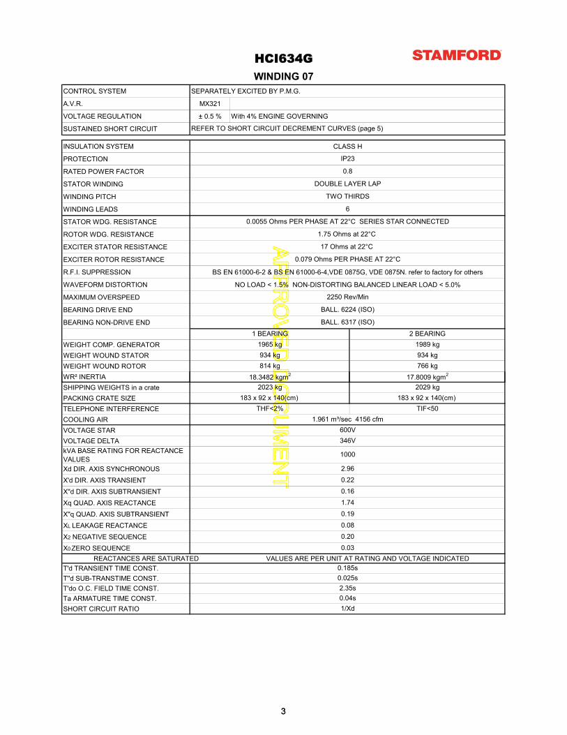
CONTROL SYSTEM SEPARATELY EXCITED BY P.M.G.
A.V.R. MX321
VOLTAGE REGULATION ± 0.5 % With 4% ENGINE GOVERNING
SUSTAINED SHORT CIRCUIT
INSULATION SYSTEM CLASS H
PROTECTION
RATED POWER FACTOR
STATOR WINDING
WINDING PITCH
WINDING LEADS
STATOR WDG. RESISTANCE
ROTOR WDG. RESISTANCE
EXCITER STATOR RESISTANCE
EXCITER ROTOR RESISTANCE
R.F.I. SUPPRESSION BS EN 61000-6-2 & BS EN 61000-6-4,VDE 0875G, VDE 0875N. refer to factory for others
WAVEFORM DISTORTION NO LOAD < 1.5% NON-DISTORTING BALANCED LINEAR LOAD < 5.0%
MAXIMUM OVERSPEED
BEARING DRIVE END
BEARING NON-DRIVE END
WEIGHT COMP. GENERATORWEIGHT WOUND STATORWEIGHT WOUND ROTORWR² INERTIA
REFER TO SHORT CIRCUIT DECREMENT CURVES (page 5)
BALL. 6317 (ISO)
1.75 Ohms at 22°C
0.0055 Ohms PER PHASE AT 22°C SERIES STAR CONNECTED
BALL. 6224 (ISO)
17 Ohms at 22°C
0.079 Ohms PER PHASE AT 22°C
18.3482 kgm2
IP23
0.8
DOUBLE LAYER LAP
TWO THIRDS
6
1989 kg1965 kg934 kg
2250 Rev/Min
934 kg
HCI634G
766 kg
17.8009 kgm2
WINDING 07
1 BEARING 2 BEARING
814 kg
SHIPPING WEIGHTS in a cratePACKING CRATE SIZETELEPHONE INTERFERENCECOOLING AIRVOLTAGE STARVOLTAGE DELTA kVA BASE RATING FOR REACTANCE VALUESXd DIR. AXIS SYNCHRONOUSX'd DIR. AXIS TRANSIENTX''d DIR. AXIS SUBTRANSIENTXq QUAD. AXIS REACTANCEX''q QUAD. AXIS SUBTRANSIENTXL LEAKAGE REACTANCEX2 NEGATIVE SEQUENCEX0 ZERO SEQUENCE
REACTANCES ARE SATURATED VALUES ARE PER UNIT AT RATING AND VOLTAGE INDICATEDT'd TRANSIENT TIME CONST.T''d SUB-TRANSTIME CONST.T'do O.C. FIELD TIME CONST.Ta ARMATURE TIME CONST.SHORT CIRCUIT RATIO
346V
1000
0.03
2.960.220.161.74
1.961 m³/sec 4156 cfm
0.190.080.20
600V
g
THF<2% TIF<50
g2029 kg
183 x 92 x 140(cm)
1/Xd
0.185s0.025s2.35s0.04s
2023 kg183 x 92 x 140(cm)
33
APPRO
VED D
OC
UM
ENT
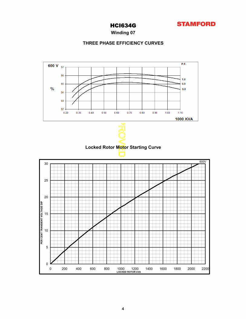
Locked Rotor Motor Starting Curve
THREE PHASE EFFICIENCY CURVES
Winding 07HCI634G
30 600V
0
5
10
15
20
25
30
0 200 400 600 800 1000 1200 1400 1600 1800 2000 2200LOCKED ROTOR kVA
PER
CEN
T TR
AN
SIEN
T VO
LTA
GE
DIP
.
600V
44
APPRO
VED D
OC
UM
ENT
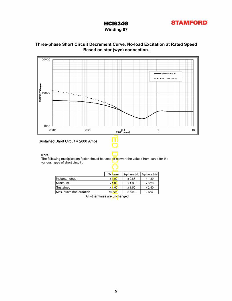
Based on star (wye) connection.
HCI634GWinding 07
Three-phase Short Circuit Decrement Curve. No-load Excitation at Rated Speed
Sustained Short Circuit = 2800 Amps
NoteThe following multiplication factor should be used to convert the values from curve for the
1000
10000
100000
0.001 0.01 0.1 1 10TIME (secs)
CU
RR
ENT
(Am
ps)
SYMMETRICAL
ASYMMETRICAL
3-phase 2-phase L-L 1-phase L-Nx 1.00 x 0.87 x 1.30x 1.00 x 1.80 x 3.20x 1.00 x 1.50 x 2.5010 sec. 5 sec. 2 sec.Max. sustained duration
All other times are unchanged
InstantaneousMinimumSustained
Sustained Short Circuit = 2800 Amps
NoteThe following multiplication factor should be used to convert the values from curve for thevarious types of short circuit :
1000
10000
100000
0.001 0.01 0.1 1 10TIME (secs)
CU
RR
ENT
(Am
ps)
SYMMETRICAL
ASYMMETRICAL
55

APPRO
VED D
OC
UM
ENT
Class - Temp Rise
Star (V)Delta (V)
kVA
kW
Efficiency (%)
kW Input
346
1046
837
94.5
769
346
1000
800
94.7
845
346
913
730
94.9
600 600
DIMENSIONS
HCI634G
Cont. F - 105/40°C Cont. H - 125/40°C Standby - 150/40°C Standby - 163/27°C
Winding 07 / 0.8 Power Factor
RATINGS
600 600
886
346
1088
870
94.4
922
60Hz
14 18 21 24
25.4 15.87 0 0
SAE
AN
60Hz
66

APPRO
VED D
OC
UM
ENT
HCI6G-07-TD-EN-SG-A
Head Office Address:Barnack Road, StamfordLincolnshire, PE9 2NB
United KingdomTel: +44 (0) 1780 484000Fax: +44 (0) 1780 484100
www.cumminsgeneratortechnologies.com
Copyright 2010, Cummins Generator Technologies Ltd, All Rights ReservedStamford and AvK are registered trade marks of Cummins Generator Technologies Ltd
Cummins and the Cummins logo are registered trade marks of Cummins Inc.
Visit www.basler.comfor additional information.
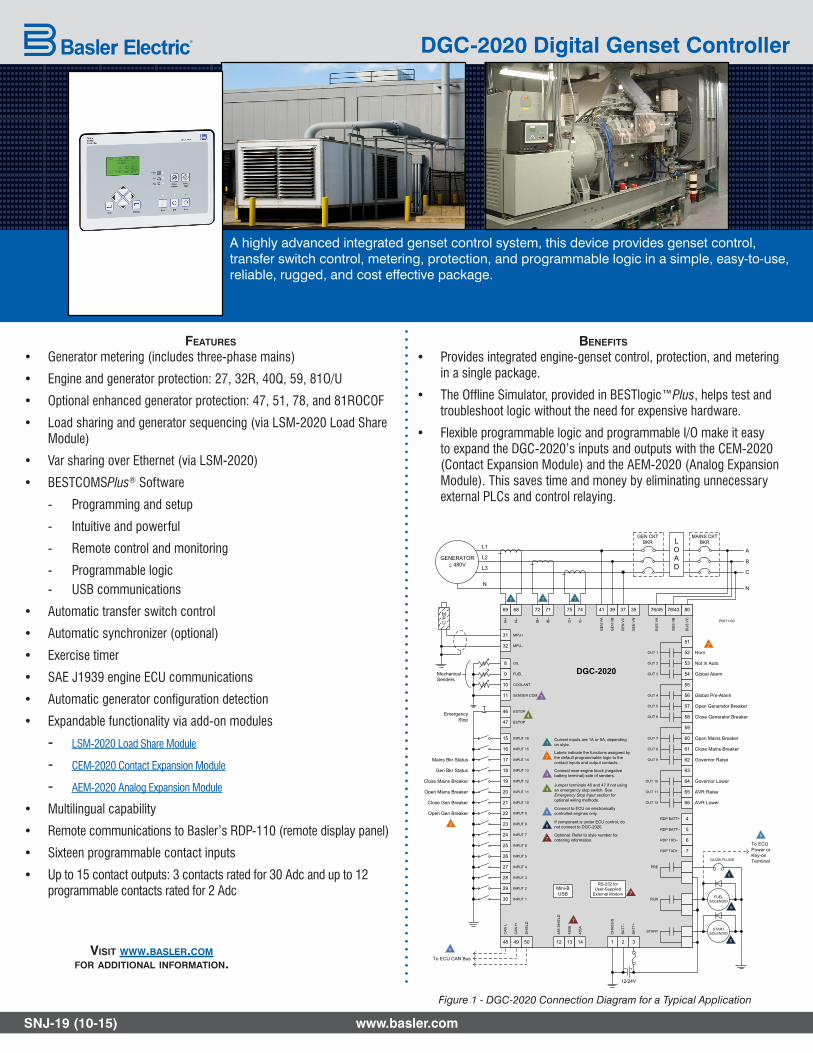
features
• Generator metering (includes three-phase mains)
• Engine and generator protection: 27, 32R, 40Q, 59, 81O/U
• Optional enhanced generator protection: 47, 51, 78, and 81ROCOF
• Load sharing and generator sequencing (via LSM-2020 Load Share Module)
• Var sharing over Ethernet (via LSM-2020)
• BESTCOMSPlus® Software
- Programming and setup
- Intuitive and powerful
- Remote control and monitoring
- Programmable logic - USB communications
• Automatic transfer switch control
• Automatic synchronizer (optional)
• Exercise timer
• SAE J1939 engine ECU communications
• $XWRPDWLF�JHQHUDWRU�FRQÀJXUDWLRQ�GHWHFWLRQ
• Expandable functionality via add-on modules
- LSM-2020 Load Share Module
- CEM-2020 Contact Expansion Module
- AEM-2020 Analog Expansion Module
• Multilingual capability
• Remote communications to Basler’s RDP-110 (remote display panel)
• Sixteen programmable contact inputs
• Up to 15 contact outputs: 3 contacts rated for 30 Adc and up to 12 programmable contacts rated for 2 Adc
benefits
• Provides integrated engine-genset control, protection, and metering in a single package.
• 7KH�2IÁLQH�6LPXODWRU��SURYLGHG�LQ�%(67ORJLF�Plus, helps test and troubleshoot logic without the need for expensive hardware.
• Flexible programmable logic and programmable I/O make it easy to expand the DGC-2020’s inputs and outputs with the CEM-2020 (Contact Expansion Module) and the AEM-2020 (Analog Expansion Module). This saves time and money by eliminating unnecessary external PLCs and control relaying.
www.basler.comSNJ-19 (10-15)
A highly advanced integrated genset control system, this device provides genset control, transfer switch control, metering, protection, and programmable logic in a simple, easy-to-use, reliable, rugged, and cost effective package.
DGC-2020 Digital Genset Controller
Figure 1 - DGC-2020 Connection Diagram for a Typical Application
GENERATORd 480V
31
32
MPU+
MPU–
69
IA–
68
IA+
72
IB–
71
IB+
75
IC–
74
IC+
41
GE
N V
A
39G
EN
VB
37
GE
N V
C
35
GE
N V
N
78/43
BU
S V
B
80
BU
S V
C
A
B
C
N
51
52OUT 1
53
54
55
56
57
58
59
60
61
62
63
64
65
66
OUT 2
OUT 3
OUT 4
OUT 5
OUT 6
OUT 7
OUT 8
OUT 9
OUT 10
OUT 11
OUT 12
PRE
RUN
START START SOLENOID
FUEL SOLENOID
2
BA
TT–
3
BA
TT+
1
CH
AS
SIS
GLOW PLUGS
8
9
OIL
FUEL
10
11
COOLANT
SENDER COM
46
47
ESTOP
ESTOP
15
16
INPUT 16
17
18
19
20
21
22
23
24
25
26
27
28
29
30
INPUT 15
INPUT 14
INPUT 13
INPUT 12
INPUT 11
INPUT 10
INPUT 8
INPUT 9
INPUT 7
INPUT 6
INPUT 5
INPUT 3
INPUT 4
INPUT 2
INPUT 1
6
RDP BATT–
7
RDP BATT+
Horn
Not in Auto
Global Alarm
Global Pre-Alarm
Open Generator Breaker
Close Generator Breaker
Open Mains Breaker
Close Mains Breaker
Governor Raise
Governor Lower
AVR Raise
AVR Lower
Emergency Stop
Mains Bkr Status
Gen Bkr Status
Close Mains Breaker
Open Mains Breaker
Close Gen Breaker
Open Gen Breaker
P0071-59
MPU
GEN CKTBKR
L1
L2
L3
N
MechanicalSenders
12/24V
5
RDP TXD–
4
RDP TXD+
Mini-B USB
RS-232 for User-Supplied
External Modem
13
485B
14
485A
12
485
SH
IELD
49
CA
N H
50
SH
IELD
48
CA
N L
2
2
7
7
1 1 1
3
4
DGC-2020
2Labels indicate the functions assigned by the default programmable logic to the contact inputs and output contacts.
1Current inputs are 1A or 5A, depending on style.
3Connect near engine block (negative battery terminal) side of senders.
4Jumper terminals 46 and 47 if not using an emergency stop switch. See Emergency Stop Input section for optional wiring methods.
7Optional. Refer to style number for ordering information.
MAINS CKTBKRL
OAD
76/45
BU
S V
A
To ECU CAN Bus
To ECUPower orKey-onTerminal
5
6
Connect to ECU on electronically controlled engines only.
If component is under ECU control, do not connect to DGC-2020.
5
5
6
6
6
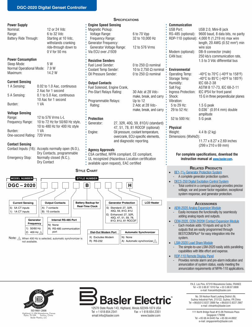
Power SupplyNominal: 12 or 24 VdcRange: 6 to 32 VdcBattery Ride Through: Starting at 10 Vdc, withstands cranking ride-through down to 0 V for 50 ms
Power ConsumptionSleep Mode: 5 W Normal Operational Mode: 7.9 W Maximum: 14.2 W
Current Sensing1 A Sensing: 0.02 to 1.0 Aac, continuous 2 Aac for 1 second5 A Sensing: 0.1 to 5.0 Aac, continuous 10 Aac for 1 secondBurden: 1 VA
Voltage SensingRange: 12 to 576 Vrms L-L Frequency Range: 10 to 72 Hz for 50/60 Hz style, 10 to 480 Hz for 400 Hz style Burden: 1 VAOne-second Rating: 720 Vrms
Contact SensingContact Inputs (16): Accepts normally open (N.O.), Dry Contacts, programmableEmergency Stop: Normally closed (N.C.), Dry Contact
Engine Speed SensingMagnetic Pickup: Voltage Range: 6 to 70 Vpp Frequency Range: 32 to 10,000 HzGenerator Frequency: Generator Voltage Range: 12 to 576 VrmsVia ECU over J1939
Resistive Senders)XHO�/HYHO�6HQGHU�� � ��WR�������QRPLQDO&RRODQW�7HPS�6HQGHU�� ���WR�������� nominal2LO�3UHVVXUH�6HQGHU������������ ��WR�������QRPLQDO
Output ContactsFuel Solenoid, Engine Crank,Pre-Start Relays Rating: 30 Adc at 28 Vdc- make, break, and carryProgrammable Relays: Up to 12 Rating: 2 Adc at 28 Vdc- make, break, and carry
ProtectionGenerator: 27, 32R, 40Q, 59, 81O/U (standard) 47, 51, 78, 81 ROCOF (optional)Engine: Oil pressure, coolant temperature, � RYHUFUDQN��(&8�VSHFLÀF�HOHPHQWV� and diagnostic reporting.
Agency Approvals&6$�FHUWLÀHG��1)3$�FRPSOLDQW��&(�FRPSOLDQW�� 8/�UHFRJQL]HG��+D]DUGRXV�/RFDWLRQ�FHUWLÀFDWLRQ�DYDLODEOH�XSRQ�UHTXHVW���($&�FHUWLÀHG
CommunicationUSB Port: USB 2.0, Mini-B jackRS-485 (optional): 9600 baud, 8 data bits, no parityRDP-110 (optional): 4,000 ft (1,219 m) max wire length, 20 AWG (0.52 mm2) min wire sizeModem (optional): DB-9 connector (male)CAN bus: 250 kb/s communication rate, 1.5 to 3 Vdc differential bus
EnvironmentalOperating Temp: -40°C to 70°C (-40°F to 158°F)Storage Temp: -40°C to 85°C (-40°F to 185°F)Humidity: IEC 68-2-38Salt Fog: ASTM B 17-73, IEC 68-2-11Ingress Protection: IEC IP54 for front panelShock: 15 G in three perpendicular planesVibration: 5 to 29 Hz: 1.5 G peak�����WR����+]�� �����ß��������PP��GRXEOH amplitude 52 to 500 Hz: 5 G peak
PhysicalWeight: 4.4 lb (2 kg)Dimensions (WxHxD): 11.77 x 8.27 x 2.69 inches (299 x 210 x 69 mm)
)RU�FRPSOHWH�VSHFLÀFDWLRQV��GRZQORDG�WKH�instruction manual at www.basler.com.
specifications
style chart
12570 State Route 143, Highland, Illinois 62249-1074 USA Tel +1 618.654.2341 Fax +1 618.654.2351email:[email protected] www.basler.com
P.A.E. Les Pins, 67319 Wasselonne Cedex, FRANCETel +33 3.88.87.1010 Fax +33 3.88.87.0808
e-mail: [email protected]
No. 59 Heshun Road Loufeng District (N), Suzhou Industrial Park, 215122, Suzhou, P.R.China
Tel +86(0)512.8227.2888 Fax +86(0)512.8227.2887e-mail: [email protected]
111 North Bridge Road #15-06 Peninsula PlazaSingapore 179098
Tel +65 68.44.6445 Fax +65 68.44.8902 e-mail: [email protected]
DGC-2020 Digital Genset Controller
related products• BE1-11g Generator Protection System
- A complete generator protection system.• DECS-250 Digital Excitation Control System
- Total control in a compact package provides precise voltage, var and power factor regulation, exceptional system response, and generator protection.
accessories• AEM-2020 Analog Expansion Module
- Easily increases the functionality by seamlessly adding analog inputs and outputs.
• CEM-2020, CEM-2020H Contact Expansion Module - Each module adds 10 inputs and up to 24
outputs that are easily programmed through BESTCOMSPlus® for easy integration into the system.
• LSM-2020 Load Share Module - The simple-to-use LSM-2020 easily adds paralleling
capabilities with little effort and expense.• RDP-110 Remote Display Panel
- Provides remote alarm and pre-alarm indication and annunciation of system status, easily meeting the annunciation requirements of NFPA-110 applications.

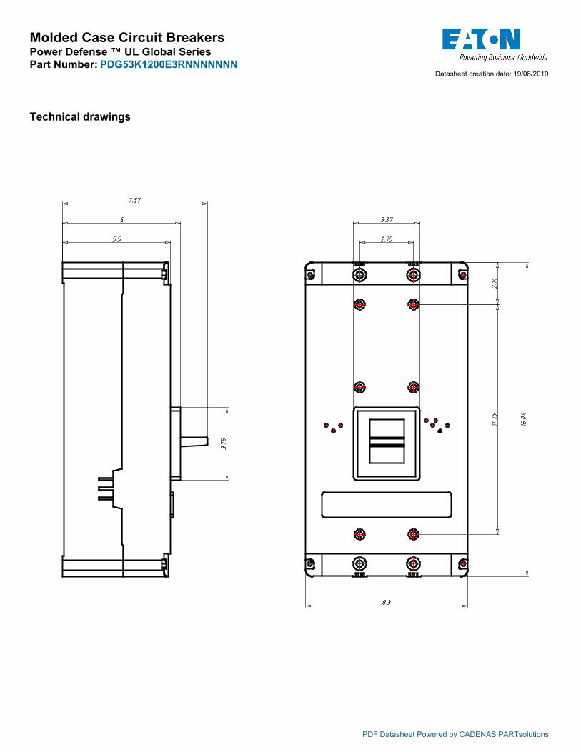
Molded Case Circuit BreakersPower Defense ™ UL Global SeriesPart Number: PDG53K1200E3RNNNNNNN
PRODUCT VIEW (Use Mouse to Rotate and Zoom)
Tech Data for Configured Product
Power Defense Catalog Number PDG53K1200E3RNNNNNNNFrame Size Frame 5Poles 3 PoleVoltage 480V ACInterruption or Breaking Capacity ( Icu/Ics) 50kAContinuous Current Rating (In) 1200ATrip Unit Type PXR20Trip Unit Options 1 LSIGTrip Unit Options 2 RelaysIndicating Accessories NoneIndicating Accessories Terminal NoneTripping Accessories NoneTripping Accessory Terminal NoneTripping Accessory Voltage NoneLine Type Description NoneLine Conductor Options N/ALine Terminal Type N/ALoad Type Description NoneLoad Conductor Options N/ALoad Terminal Type N/ASpecial Options - Type of Modification NoneDetails NoneAdditional Description None
PDF Datasheet Powered by CADENAS PARTsolutions
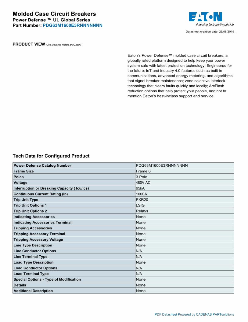
Eaton’s Power Defense™ molded case circuit breakers, a globally rated platform designed to help keep your power system safe with latest protection technology. Engineered for the future: IoT and Industry 4.0 features such as built-in communications, advanced energy metering, and algorithms that signal breaker maintenance; zone selective interlock technology that clears faults quickly and locally; ArcFlash reduction options that help protect your people, and not to mention Eaton’s best-inclass support and service.
Datasheet creation date: 19/08/2019 18:17
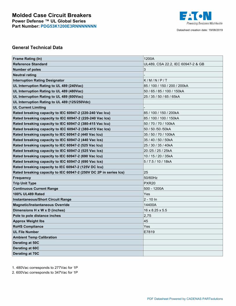
Molded Case Circuit BreakersPower Defense ™ UL Global SeriesPart Number: PDG53K1200E3RNNNNNNN
PDF Datasheet Powered by CADENAS PARTsolutions
Technical drawings
Datasheet creation date: 19/08/2019 18:17
Molded Case Circuit BreakersPower Defense ™ UL Global SeriesPart Number: PDG53K1200E3RNNNNNNN
PDF Datasheet Powered by CADENAS PARTsolutions
Datasheet creation date: 19/08/2019 18:17
General Technical Data
Frame Rating (In) 1200AReference Standard UL489, CSA 22.2, IEC 60947-2 & GBNumber of poles 3Neutral rating -Interruption Rating Designator K / M / N / P / TUL Interruption Rating to UL 489 (240Vac) 85 / 100 / 150 / 200 / 200kAUL Interruption Rating to UL 489 (480Vac) 50 / 65 / 85 / 100 / 150kAUL Interruption Rating to UL 489 (600Vac) 25 / 35 / 50 / 65 / 65kAUL Interruption Rating to UL 489 (125/250Vdc)UL Current Limiting -Rated breaking capacity to IEC 60947-2 (220-240 Vac lcu) 85 / 100 / 150 / 200kARated breaking capacity to IEC 60947-2 (220-240 Vac lcs) 85 / 100 / 100 / 150kARated breaking capacity to IEC 60947-2 (380-415 Vac lcu) 50 / 70 / 70 / 100kARated breaking capacity to IEC 60947-2 (380-415 Vac lcs) 50 / 50 /50 /50kARated breaking capacity to IEC 60947-2 (440 Vac lcu) 35 / 50 / 70 / 100kARated breaking capacity to IEC 60947-2 (440 Vac lcs) 35 / 40 / 50 / 50kARated breaking capacity to IEC 60947-2 (525 Vac lcu) 25 / 30 / 35 / 40kARated breaking capacity to IEC 60947-2 (525 Vac lcs) 20 /25 / 25 / 25kARated breaking capacity to IEC 60947-2 (690 Vac lcu) 10 / 15 / 20 / 35kARated breaking capacity to IEC 60947-2 (690 Vac lcs) 5 / 7.5 / 10 / 18kARated breaking capacity to IEC 60947-2 (125V DC lcu)Rated breaking capacity to IEC 60947-2 (250V DC 2P in series lcs) 25Frequency 50/60HzTrip Unit Type PXR20Continuous Current Range 500 - 1200A100% UL489 Rated YesInstantaneous/Short Circuit Range 2 - 10 InMagnetic/Instantaneous Override 14400ADimensions H x W x D (inches) 16 x 8.25 x 5.5Pole to pole distance inches 2,75Approx Weight lbs 45RoHS Compliance YesUL File Number E7819Ambient Temp CalibrationDerating at 50CDerating at 60CDerating at 70C
1. 480Vac corresponds to 277Vac for 1P 2. 600Vac corresponds to 347Vac for 1P
Molded Case Circuit BreakersPower Defense ™ UL Global SeriesPart Number: PDG63M1600E3RNNNNNNN
PRODUCT VIEW (Use Mouse to Rotate and Zoom)
Tech Data for Configured Product
Power Defense Catalog Number PDG63M1600E3RNNNNNNNFrame Size Frame 6Poles 3 PoleVoltage 480V ACInterruption or Breaking Capacity ( Icu/Ics) 65kAContinuous Current Rating (In) 1600ATrip Unit Type PXR20Trip Unit Options 1 LSIGTrip Unit Options 2 RelaysIndicating Accessories NoneIndicating Accessories Terminal NoneTripping Accessories NoneTripping Accessory Terminal NoneTripping Accessory Voltage NoneLine Type Description NoneLine Conductor Options N/ALine Terminal Type N/ALoad Type Description NoneLoad Conductor Options N/ALoad Terminal Type N/ASpecial Options - Type of Modification NoneDetails NoneAdditional Description None
PDF Datasheet Powered by CADENAS PARTsolutions
Eaton’s Power Defense™ molded case circuit breakers, a globally rated platform designed to help keep your power system safe with latest protection technology. Engineered for the future: IoT and Industry 4.0 features such as built-in communications, advanced energy metering, and algorithms that signal breaker maintenance; zone selective interlock technology that clears faults quickly and locally; ArcFlash reduction options that help protect your people, and not to mention Eaton’s best-inclass support and service.
Datasheet creation date: 26/08/2019 21:03
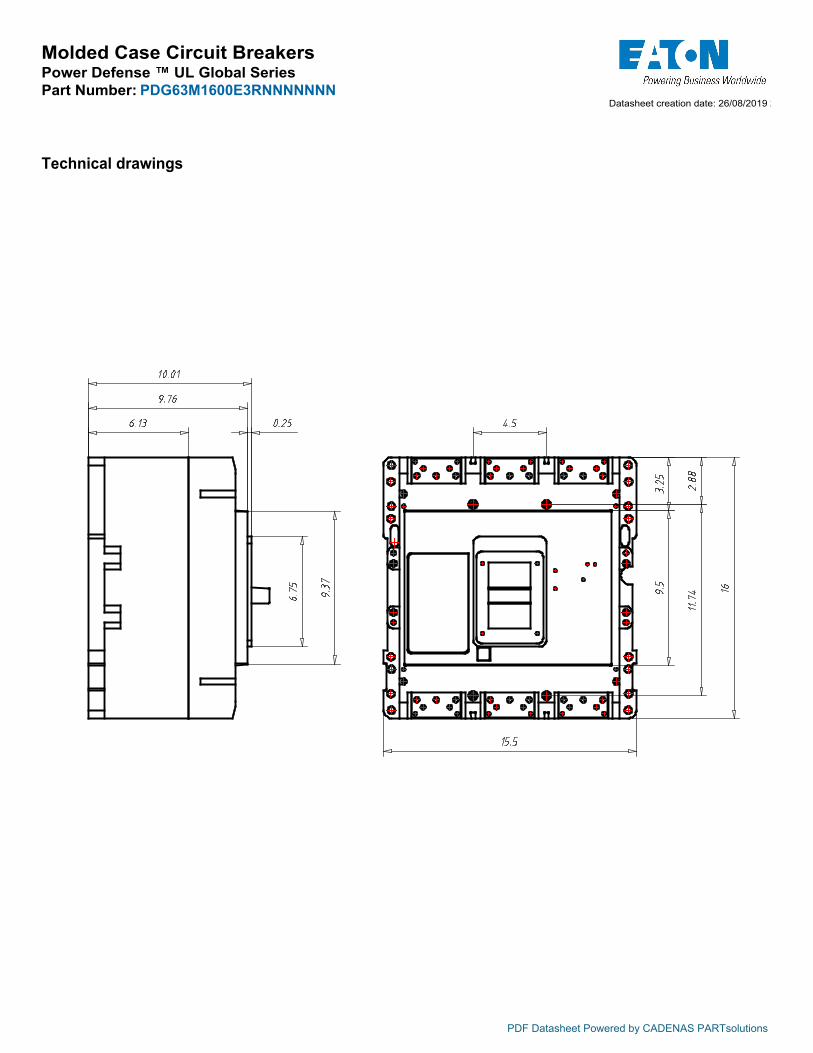
Molded Case Circuit BreakersPower Defense ™ UL Global SeriesPart Number: PDG63M1600E3RNNNNNNN
PDF Datasheet Powered by CADENAS PARTsolutions
Technical drawings
Datasheet creation date: 26/08/2019 21:03

Molded Case Circuit BreakersPower Defense ™ UL Global SeriesPart Number: PDG63M1600E3RNNNNNNN
PDF Datasheet Powered by CADENAS PARTsolutions
Datasheet creation date: 26/08/2019 21:03
General Technical Data
Frame Rating (In) 1600AReference Standard UL489, CSA 22.2, IEC 60947-2 & GBNumber of poles 3Neutral rating -Interruption Rating Designator M / N / PUL Interruption Rating to UL 489 (240Vac) 125 / 150 / 200kAUL Interruption Rating to UL 489 (480Vac) 65 / 85 / 100kAUL Interruption Rating to UL 489 (600Vac) 35 / 50 / 65kAUL Interruption Rating to UL 489 (125/250Vdc)UL Current Limiting -Rated breaking capacity to IEC 60947-2 (220-240 Vac lcu) 135 / 150 / 200kARated breaking capacity to IEC 60947-2 (220-240 Vac lcs) 100 / 100 / 100kARated breaking capacity to IEC 60947-2 (380-415 Vac lcu) 70 / 70 / 100kARated breaking capacity to IEC 60947-2 (380-415 Vac lcs) 50 / 50 / 50kARated breaking capacity to IEC 60947-2 (440 Vac lcu) 50 / 70 / 100kARated breaking capacity to IEC 60947-2 (440 Vac lcs) 40 / 50 / 50kARated breaking capacity to IEC 60947-2 (525 Vac lcu) 30 / 35 / 40kARated breaking capacity to IEC 60947-2 (525 Vac lcs) 25 / 25 / 25kARated breaking capacity to IEC 60947-2 (690 Vac lcu) 15 / 20 / 35kARated breaking capacity to IEC 60947-2 (690 Vac lcs) 7. 5 / 13 / 18kARated breaking capacity to IEC 60947-2 (125V DC lcu)Rated breaking capacity to IEC 60947-2 (250V DC 2P in series lcs) 25Frequency 50/60HzTrip Unit Type PXR20Continuous Current Range Fixed100% UL489 Rated YesInstantaneous/Short Circuit Range AdjustableMagnetic/Instantaneous Override 17500ADimensions H x W x D (inches) 16 x 15.5 x 9.75Pole to pole distance inches 4,5Approx Weight lbs 135RoHS Compliance YesUL File Number E7819Ambient Temp CalibrationDerating at 50CDerating at 60CDerating at 70C
1. 480Vac corresponds to 277Vac for 1P 2. 600Vac corresponds to 347Vac for 1P

Molded Case Circuit BreakersPower Defense ™ UL Global SeriesPart Number: PDG63M2500E3RNNNNNNN
PRODUCT VIEW (Use Mouse to Rotate and Zoom)
Tech Data for Configured Product
Power Defense Catalog Number PDG63M2500E3RNNNNNNNFrame Size Frame 6Poles 3 PoleVoltage 480V ACInterruption or Breaking Capacity ( Icu/Ics) 65kAContinuous Current Rating (In) 2500ATrip Unit Type PXR20Trip Unit Options 1 LSIGTrip Unit Options 2 RelaysIndicating Accessories NoneIndicating Accessories Terminal NoneTripping Accessories NoneTripping Accessory Terminal NoneTripping Accessory Voltage NoneLine Type Description NoneLine Conductor Options NoneLine Terminal Type N/ALoad Type Description NoneLoad Conductor Options NoneLoad Terminal Type N/ASpecial Options - Type of Modification NoneDetails NoneAdditional Description None
PDF Datasheet Powered by CADENAS PARTsolutions
Eaton’s Power Defense™ molded case circuit breakers, a globally rated platform designed to help keep your power system safe with latest protection technology. Engineered for the future: IoT and Industry 4.0 features such as built-in communications, advanced energy metering, and algorithms that signal breaker maintenance; zone selective interlock technology that clears faults quickly and locally; ArcFlash reduction options that help protect your people, and not to mention Eaton’s best-inclass support and service.
Datasheet creation date: 02/12/2019 18:05
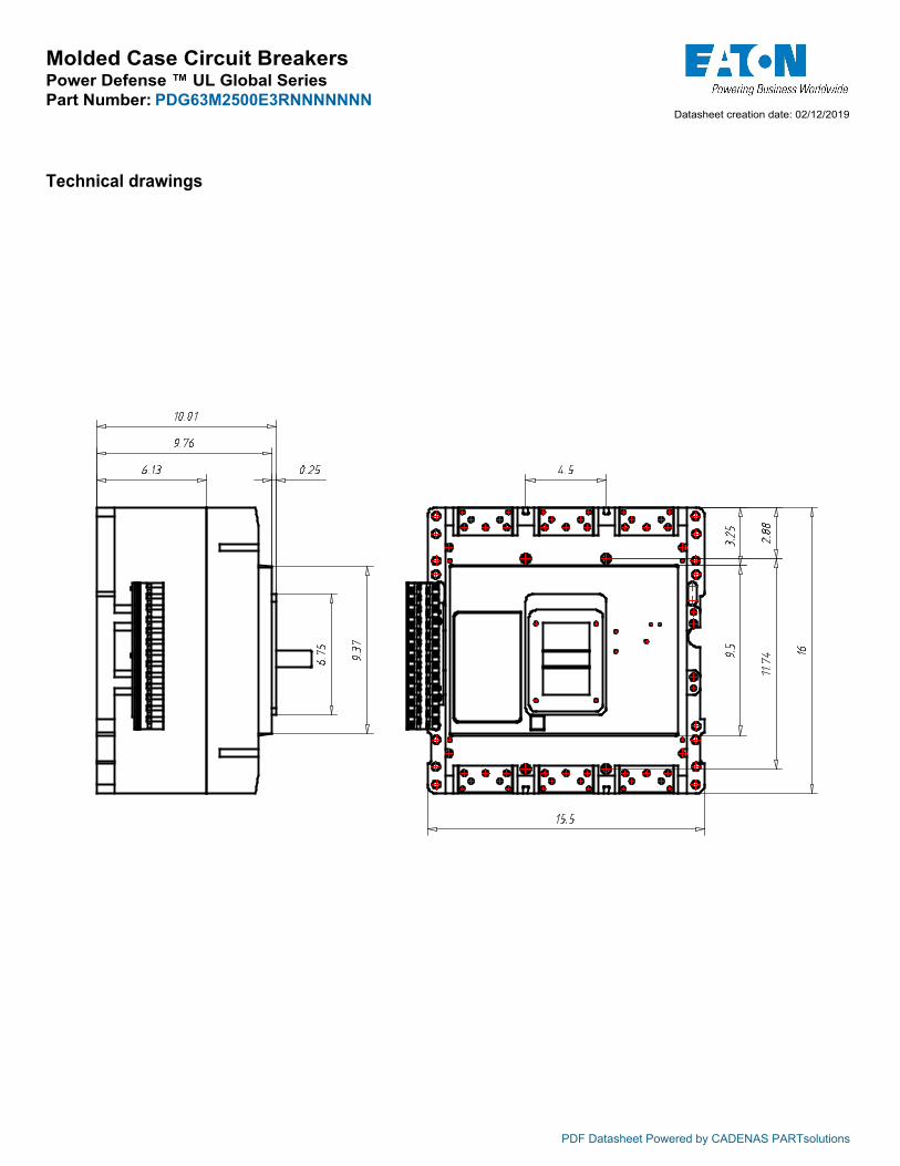
Molded Case Circuit BreakersPower Defense ™ UL Global SeriesPart Number: PDG63M2500E3RNNNNNNN
PDF Datasheet Powered by CADENAS PARTsolutions
Technical drawings
Datasheet creation date: 02/12/2019 18:05
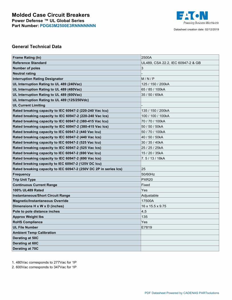
Molded Case Circuit BreakersPower Defense ™ UL Global SeriesPart Number: PDG63M2500E3RNNNNNNN
PDF Datasheet Powered by CADENAS PARTsolutions
Datasheet creation date: 02/12/2019 18:05
General Technical Data
Frame Rating (In) 2500AReference Standard UL489, CSA 22.2, IEC 60947-2 & GBNumber of poles 3Neutral rating -Interruption Rating Designator M / N / PUL Interruption Rating to UL 489 (240Vac) 125 / 150 / 200kAUL Interruption Rating to UL 489 (480Vac) 65 / 85 / 100kAUL Interruption Rating to UL 489 (600Vac) 35 / 50 / 65kAUL Interruption Rating to UL 489 (125/250Vdc)UL Current Limiting -Rated breaking capacity to IEC 60947-2 (220-240 Vac lcu) 135 / 150 / 200kARated breaking capacity to IEC 60947-2 (220-240 Vac lcs) 100 / 100 / 100kARated breaking capacity to IEC 60947-2 (380-415 Vac lcu) 70 / 70 / 100kARated breaking capacity to IEC 60947-2 (380-415 Vac lcs) 50 / 50 / 50kARated breaking capacity to IEC 60947-2 (440 Vac lcu) 50 / 70 / 100kARated breaking capacity to IEC 60947-2 (440 Vac lcs) 40 / 50 / 50kARated breaking capacity to IEC 60947-2 (525 Vac lcu) 30 / 35 / 40kARated breaking capacity to IEC 60947-2 (525 Vac lcs) 25 / 25 / 25kARated breaking capacity to IEC 60947-2 (690 Vac lcu) 15 / 20 / 35kARated breaking capacity to IEC 60947-2 (690 Vac lcs) 7. 5 / 13 / 18kARated breaking capacity to IEC 60947-2 (125V DC lcu)Rated breaking capacity to IEC 60947-2 (250V DC 2P in series lcs) 25Frequency 50/60HzTrip Unit Type PXR20Continuous Current Range Fixed100% UL489 Rated YesInstantaneous/Short Circuit Range AdjustableMagnetic/Instantaneous Override 17500ADimensions H x W x D (inches) 16 x 15.5 x 9.75Pole to pole distance inches 4,5Approx Weight lbs 135RoHS Compliance YesUL File Number E7819Ambient Temp CalibrationDerating at 50CDerating at 60CDerating at 70C
1. 480Vac corresponds to 277Vac for 1P 2. 600Vac corresponds to 347Vac for 1P

3
Main characteristics
The Tmax family, conforming to the UL 489 and CSA C22.2 No. 5.1 Standards, is enriched with the Tmax T8 size, which allows 3000 A to be reached. Also available in the 1600 A, 2000 A and 2500 A frames, Tmax T8 is equipped with the same electronic trip units as Tmax T7, thereby guaranteeing extremely high performances able to satisfy all installation requirements. Adequately sized for the performances offered (W=16.8 / D=11.2 / H=15.0 in). Tmax T8 is able to interrupt the following short-circuit currents: 125 kA@480 V and 100 kA@600 V.
1SDC210026D0201
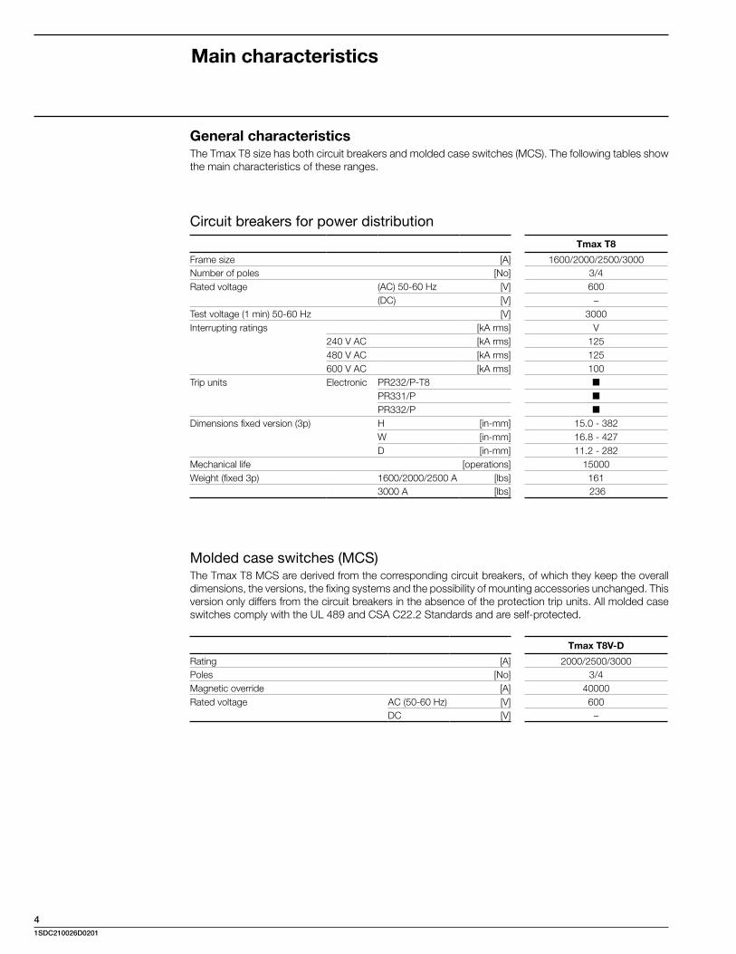
4
Main characteristics
General characteristics The Tmax T8 size has both circuit breakers and molded case switches (MCS). The following tables show the main characteristics of these ranges.
Circuit breakers for power distributionTmax T8
Frame size [A] 1600/2000/2500/3000Number of poles [No] 3/4Rated voltage (AC) 50-60 Hz [V] 600
(DC) [V] –Test voltage (1 min) 50-60 Hz [V] 3000Interrupting ratings [kA rms] V
240 V AC [kA rms] 125480 V AC [kA rms] 125600 V AC [kA rms] 100
Trip units Electronic PR232/P-T8 ■
PR331/P ■
PR332/P ■
Dimensions fixed version (3p) H [in-mm] 15.0 - 382 W [in-mm] 16.8 - 427 D [in-mm] 11.2 - 282Mechanical life [operations] 15000Weight (fixed 3p) 1600/2000/2500 A [lbs] 161
3000 A [lbs] 236
Molded case switches (MCS)The Tmax T8 MCS are derived from the corresponding circuit breakers, of which they keep the overall dimensions, the versions, the fixing systems and the possibility of mounting accessories unchanged. This version only differs from the circuit breakers in the absence of the protection trip units. All molded case switches comply with the UL 489 and CSA C22.2 Standards and are self-protected.
Tmax T8V-D
Rating [A] 2000/2500/3000Poles [No] 3/4Magnetic override [A] 40000Rated voltage AC (50-60 Hz) [V] 600 DC [V] –
1SDC210026D0201

Specifications (cont.) x� New 4-color package design
Digital Linear Chargers
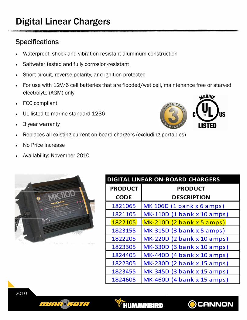
Specifications x� Waterproof, shock-and vibration-resistant aluminum construction
x� Saltwater tested and fully corrosion-resistant
x� Short circuit, reverse polarity, and ignition protected
x� For use with 12V/6 cell batteries that are flooded/wet cell, maintenance free or starved electrolyte (AGM) only
x� FCC compliant
x� UL listed to marine standard 1236
x� 3 year warranty
x� Replaces all existing current on-board chargers (excluding portables)
x� No Price Increase
x� Availability: November 2010
Digital Linear Chargers
DIGITAL�LINEAR�ONͲBOARD�CHARGERS
PRODUCT PRODUCTCODE DESCRIPTION
1821065 MK�106D�(1�bank�x�6�amps)1821105 MKͲ110D�(1�bank�x�10�amps)1822105 MKͲ210D�(2�bank�x�5�amps)1823155 MKͲ315D�(3�bank�x�5�amps)1822205 MKͲ220D�(2�bank�x�10�amps)1823305 MKͲ330D�(3�bank�x�10�amps)1824405 MKͲ440D�(4�bank�x�10�amps)1822305 MKͲ230D�(2�bank�x�15�amps)1823455 MKͲ345D�(3�bank�x�15�amps)1824605 MKͲ460D�(4�bank�x�15�amps)
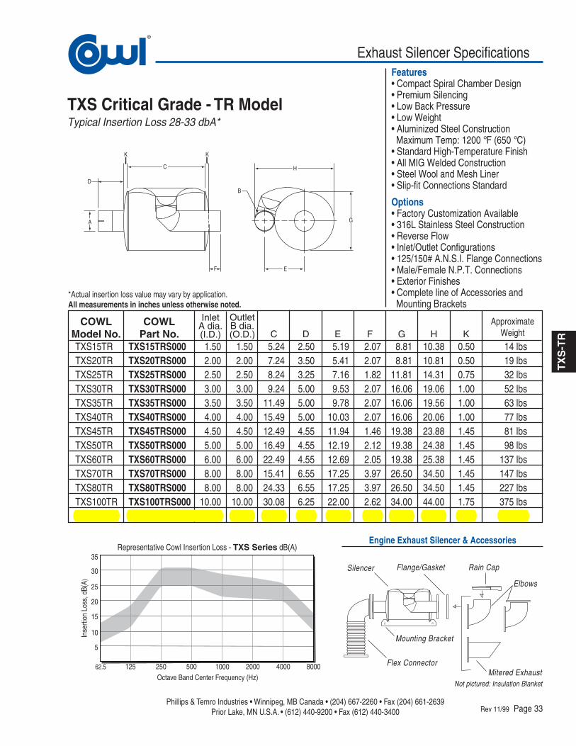
Exhaust Silencer Specifications®
62.5 125 250 500 1000 2000 4000 8000
5
10
15
20
25
30
35Representative Cowl Insertion Loss - TXS Series dB(A)
Octave Band Center Frequency (Hz)
Inse
rtion
Los
s, d
B(A)
Phillips & Temro Industries • Winnipeg, MB Canada • (204) 667-2260 • Fax (204) 661-2639Prior Lake, MN U.S.A. • (612) 440-9200 • Fax (612) 440-3400
Features• Compact Spiral Chamber Design• Premium Silencing• Low Back Pressure• Low Weight• Aluminized Steel Construction Maximum Temp: 1200 °F (650 °C)• Standard High-Temperature Finish• All MIG Welded Construction• Steel Wool and Mesh Liner• Slip-fit Connections Standard
Options• Factory Customization Available• 316L Stainless Steel Construction• Reverse Flow• Inlet/Outlet Configurations• 125/150# A.N.S.I. Flange Connections• Male/Female N.P.T. Connections• Exterior Finishes• Complete line of Accessories and Mounting Brackets
Engine Exhaust Silencer & Accessories
Rev 11/99 Page 33
TXS Critical Grade - TR ModelTypical Insertion Loss 28-33 dbA*
TXS15TR TXS15TRS000 1.50 1.50 5.24 2.50 5.19 2.07 8.81 10.38 0.50 14 lbsTXS20TR TXS20TRS000 2.00 2.00 7.24 3.50 5.41 2.07 8.81 10.81 0.50 19 lbsTXS25TR TXS25TRS000 2.50 2.50 8.24 3.25 7.16 1.82 11.81 14.31 0.75 32 lbsTXS30TR TXS30TRS000 3.00 3.00 9.24 5.00 9.53 2.07 16.06 19.06 1.00 52 lbsTXS35TR TXS35TRS000 3.50 3.50 11.49 5.00 9.78 2.07 16.06 19.56 1.00 63 lbsTXS40TR TXS40TRS000 4.00 4.00 15.49 5.00 10.03 2.07 16.06 20.06 1.00 77 lbsTXS45TR TXS45TRS000 4.50 4.50 12.49 4.55 11.94 1.46 19.38 23.88 1.45 81 lbsTXS50TR TXS50TRS000 5.00 5.00 16.49 4.55 12.19 2.12 19.38 24.38 1.45 98 lbsTXS60TR TXS60TRS000 6.00 6.00 22.49 4.55 12.69 2.05 19.38 25.38 1.45 137 lbsTXS70TR TXS70TRS000 8.00 8.00 15.41 6.55 17.25 3.97 26.50 34.50 1.45 147 lbsTXS80TR TXS80TRS000 8.00 8.00 24.33 6.55 17.25 3.97 26.50 34.50 1.45 227 lbsTXS100TR TXS100TRS000 10.00 10.00 30.08 6.25 22.00 2.62 34.00 44.00 1.75 375 lbsTXS120TR TXS120TRS000 12.00 12.00 36.08 5.75 26.00 3.71 40.00 52.00 2.25 532 lbs
COWLModel No.
InletA dia.(I.D.)
OutletB dia.(O.D.) C
COWLPart No. D E F G H K
*Actual insertion loss value may vary by application.All measurements in inches unless otherwise noted.
C H
B
G
EF
A
D
KK
TXS
-TR
Silencer
Flex Connector
Mounting Bracket
Rain Cap
Mitered Exhaust
Flange/Gasket
Not pictured: Insulation Blanket
ApproximateWeight
Elbows