Embed Size (px)
Citation preview
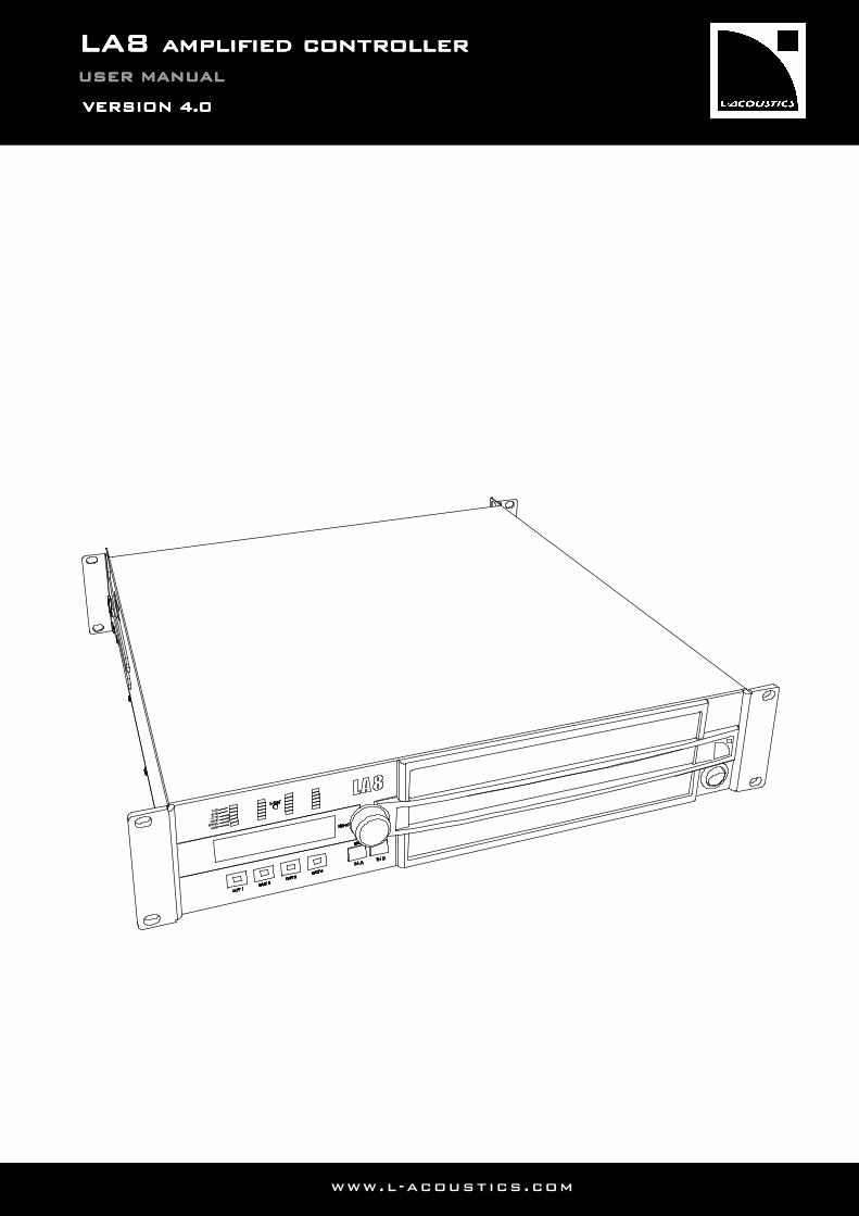
LLLLA8A8A8A8 aaaamplified controllermplified controllermplified controllermplified controller
USER MANUALUSER MANUALUSER MANUALUSER MANUAL
VERSION VERSION VERSION VERSION 4444....0000
www.l-acoustics.com

w ww . l - a c o u s t i c s . co m
LA4 LA4 LA4 LA4 CONTROLEUR AMPLIFIECONTROLEUR AMPLIFIECONTROLEUR AMPLIFIECONTROLEUR AMPLIFIE
LA8_UM_EN_4-0 www . l - a co ust i c s . c o m 1111
1111 SAFETY WARNINGSSAFETY WARNINGSSAFETY WARNINGSSAFETY WARNINGS
All information hereafter detailed applies to the L-ACOUSTICS® LA8 Amplified Controller, designated in this section as ‘‘the product’’. Where necessary, a distinction will be drawn between the LA8, LA8US, and LA8JP respectively of CE, US, and Japan types.
1.1 Symbol description
1.1.1 Symbols employed in this manual
Throughout this manual the potential risks are indicated by the following symbols:
The VOLTAGE symbol indicates a potential risk of electric shock that could be life threatening. In addition, the product may also be seriously damaged.
The WARNING symbol indicates a potential risk of physical harm to the user or people within close proximity to the product. In addition, the product may also be damaged.
The CAUTION symbol notifies the user about information to prevent possible product damage.
The IMPORTANT symbol is a notification of an important recommendation of use.
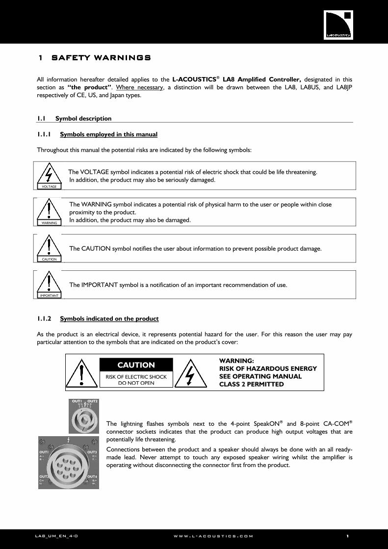
1.1.2 Symbols indicated on the product
As the product is an electrical device, it represents potential hazard for the user. For this reason the user may pay particular attention to the symbols that are indicated on the product’s cover:
The lightning flashes symbols next to the 4-point SpeakON® and 8-point CA-COM® connector sockets indicates that the product can produce high output voltages that are potentially life threatening.
Connections between the product and a speaker should always be done with an all ready-made lead. Never attempt to touch any exposed speaker wiring whilst the amplifier is operating without disconnecting the connector first from the product.
CAUTION
RISK OF ELECTRIC SHOCK DO NOT OPEN
WARNING:
RISK OF HAZARDOUS ENERGY SEE OPERATING MANUAL
CLASS 2 PERMITTED
VOLTAGE
WARNING
CAUTION
IMPORTANT
LALALALA8888 AMPLIFIED CONTROLLERAMPLIFIED CONTROLLERAMPLIFIED CONTROLLERAMPLIFIED CONTROLLER USER MANUALUSER MANUALUSER MANUALUSER MANUAL VERSION 4.0
LA8_UM_EN_4-0 www . l - a co ust i c s . c o m 2222
1.2 Important safety instructions
1. Read this manual
2. Heed all safety warnings
3. Follow all instructions
4. The user should never incorporate equipment or accessories not approved by L-ACOUSTICS®
5. Environments
Use the product only in E1, E2, E3, or E4 environments according to EN55103-2 standard.
6. Radio interference
A sample of this product has been tested and complies with the limits for the EMC (Electro Magnetic Compatibility) directive. These limits are designed to provide reasonable protection against harmful interference from electrical equipment. However, there is no guarantee that interference will not occur in a particular installation.
7. Power cord caution
Do not use the product if the power cord is broken or frayed. Protect the power cord from being walked upon or pinched - particularly at the plugs and the point where the power cord exits from the apparatus.
8. Mains supply
ONLY connect the LA8 or LA8US to an AC power outlet rated 230 V, 16 A, 50 - 60 Hz or 120 V, 30 A, 50-60 Hz. ONLY connect the LA8JP to an AC power outlet rated 100 V, 30 A, 50 - 60 Hz or 200 V, 15 A, 50-60 Hz.
9. Three-phase circuit VERIFY the electrical conformity and availability of each connection, in particular the neutral one. BALANCE the loads between the three phases. NEVER connect an LA8 or LA8US to two live wires of a 120 V three-phase circuit (in order to use it in the 230 V mode). NEVER connect an LA8JP to two live wires of a 100 V three-phase circuit (in order to use it in the 200 V mode).
10. Electrical generator FIRST power the generator on and THEN power the amplified controllers on. VERIFY that the amplified controllers are turned off before powering the generator on.
11. Thermal circuit breaker
ALWAYS interconnect a thermal circuit breaker between the product and the mains supply. The circuit breaker current rating depends on the mains voltage rating as follows: 16 A for 230 V or 30 A for 120 V (LA8 or LA8US), 15 A for 200 V or 30 A for 100 V (LA8JP).
12. Grounding
The product may only be connected to mains power supply fitted with a grounding-type outlet tied to earth. Do not defeat the outlet’s ground pin as it connects the product to earth. If the local outlet is obsolete, consult an electrician. The product is fitted with a grounding-type plug. Do not defeat the ground wire connecting the plug’s female contact to the product’s chassis.
IMPORTANT
IMPORTANT
VOLTAGE
VOLTAGE
VOLTAGE
VOLTAGE
VOLTAGE
CAUTION
LA8_UM_EN_4-0 www . l - a co ust i c s . c o m 3333
13. Plug replacement
If the AC plug on the power supply cord of this product does not match the local outlet, it must be replaced by an appropriate one. This operation should only be performed by qualified service personnel. Make sure the cut-off plug is withdrawn from use, as it can cause severe electrical shock if connected to an AC outlet.
14. Lightning storm
During lightning storms, disconnect the product from the mains power supply. Switching the product off does not disconnect it from the mains power supply. Therefore, disconnecting can only be achieved by removing the plug from the mains outlet.
15. Interconnections
When connecting the product to other equipment, mute all output channels. Carefully read the user manual of the other equipment and follow the instructions when making the connections. Do not connect a speaker output in parallel or series with any other amplifier’s output. Do not connect the speaker outputs to any other voltage source, such as a battery, mains source, or power supply, regardless of whether the product is turned on or off.
16. Over power risks
The product is very powerful and can be potentially dangerous to both loudspeakers and humans alike. Even when using the product’s front panel attenuator to reduce the gain, it is still possible to reach full output power if the input signal level is high enough.
17. Operating temperature
The product’s operating temperature is comprised between -5°C and +50°C.
18. Ventilation
Openings in the product’s cabinet are provided for ventilation to ensure reliable operation of the product by protecting it from overheating. These openings must not be blocked or covered. This product should be installed in accordance with the manufacturer instructions given in this manual.
19. Heat Do not operate the product near any heat source, such as radiators or other devices.
20. Water and moisture
To prevent fire or shock hazard, do not expose the product to rain or moisture. Do not use the product near water. Do not operate the product while wet.
21. Interference with external objects and/or liquids
Never push objects of any kind into the product through openings as they may touch dangerous voltage points or short out parts that could result in a fire or electric shock. Never spill liquid of any kind on the product.
22. Cleaning
Unplug the product from the mains power supply before cleaning. Do not use liquid or aerosol cleaners. Clean only with dry cloth.
23. Mounting instructions
Do not place the product on an unstable cart, stand, tripod, bracket, or table. The product may fall and be seriously damaged, and may cause serious human injury. Any mounting of the product should follow the manufacturer’s instructions given in this manual, and should use accessories recommended by the manufacturer.
WARNING
CAUTION
CAUTION
CAUTION
CAUTION
VOLTAGE
VOLTAGE
VOLTAGE
VOLTAGE
CAUTION
VOLTAGE
LALALALA8888 AMPLIFIED CONTROLLERAMPLIFIED CONTROLLERAMPLIFIED CONTROLLERAMPLIFIED CONTROLLER USER MANUALUSER MANUALUSER MANUALUSER MANUAL VERSION 4.0
LA8_UM_EN_4-0 www . l - a co ust i c s . c o m 4444
24. Conditions which require immediate service
Refer all servicing to qualified service personnel. Servicing is required when the product has been damaged in any way such as:
• Power supply cord or plug is damaged,
• Liquid has been spilled or an object has fallen into the product,
• The product has been exposed to rain or moisture,
• The product was dropped or the housing is damaged,
• The product does not operate normally.
25. Servicing and replacement parts
Do not attempt to service this product as removing covers may expose to dangerous voltage or other hazards. The use of unauthorized replacement parts may result in injury and/or damage through fire, electric shock, or other electricity-related hazards. All service and repair work must be carried out by an L-ACOUSTICS® authorized dealer.
26. Shipping
Use the original packaging for shipping the product, unless it is mounted in a rack with the front and rear panels fixed to the rack, as described in this manual.
27. Manual
Keep this manual in a safe place during the product lifetime. This manual forms an integral part of the product. Reselling of the product is only possible if the user manual is available. Any changes made to the product have to be documented in writing and passed on to the buyer in the event of resale.
VOLTAGE
VOLTAGE
CAUTION
IMPORTANT
LA8_UM_EN_4-0 www . l - a co ust i c s . c o m 5555
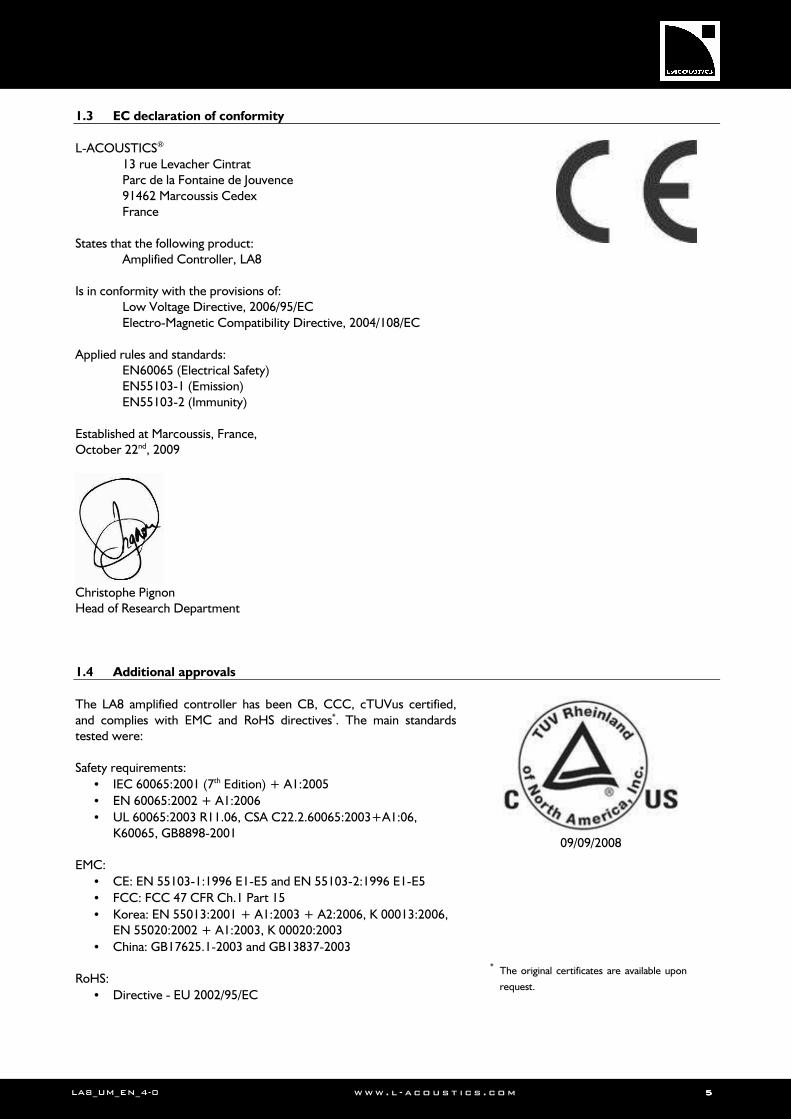
1.3 EC declaration of conformity
L-ACOUSTICS®
13 rue Levacher Cintrat Parc de la Fontaine de Jouvence 91462 Marcoussis Cedex France
States that the following product:
Amplified Controller, LA8 Is in conformity with the provisions of:
Low Voltage Directive, 2006/95/EC Electro-Magnetic Compatibility Directive, 2004/108/EC
Applied rules and standards:
EN60065 (Electrical Safety) EN55103-1 (Emission) EN55103-2 (Immunity)
Established at Marcoussis, France, October 22nd, 2009
Christophe Pignon Head of Research Department
1.4 Additional approvals
The LA8 amplified controller has been CB, CCC, cTUVus certified, and complies with EMC and RoHS directives*. The main standards tested were: Safety requirements:
• IEC 60065:2001 (7th Edition) + A1:2005
• EN 60065:2002 + A1:2006
• UL 60065:2003 R11.06, CSA C22.2.60065:2003+A1:06, K60065, GB8898-2001
EMC:
• CE: EN 55103-1:1996 E1-E5 and EN 55103-2:1996 E1-E5
• FCC: FCC 47 CFR Ch.1 Part 15
• Korea: EN 55013:2001 + A1:2003 + A2:2006, K 00013:2006, EN 55020:2002 + A1:2003, K 00020:2003
• China: GB17625.1-2003 and GB13837-2003 RoHS:
• Directive - EU 2002/95/EC
09/09/2008
* The original certificates are available upon
request.
LALALALA8888 AMPLIFIED CONTROLLERAMPLIFIED CONTROLLERAMPLIFIED CONTROLLERAMPLIFIED CONTROLLER USER MANUALUSER MANUALUSER MANUALUSER MANUAL VERSION 4.0
LA8_UM_EN_4-0 www . l - a co ust i c s . c o m 6666
2222 CONTENTSCONTENTSCONTENTSCONTENTS
1 SAFETY WARNINGS 1
1.1 Symbol description .................................................................................................................................................. 1
1.1.1 Symbols employed in this manual ............................................................................................................ 1
1.1.2 Symbols indicated on the product ........................................................................................................... 1
1.2 Important safety instructions ................................................................................................................................... 2
1.3 EC declaration of conformity .................................................................................................................................. 5
1.4 Additional approvals ................................................................................................................................................ 5
2 CONTENTS 6
3 INTRODUCTION 8
3.1 Welcome to L-ACOUSTICS®.................................................................................................................................. 8
3.2 Unpacking ................................................................................................................................................................ 8
3.3 Cross-references ..................................................................................................................................................... 9
3.4 Web links ................................................................................................................................................................. 9
4 COMPLETE SYSTEM APPROACH 10
4.1 LA8 Presentation ................................................................................................................................................... 10
4.2 Loudspeaker system configurations ....................................................................................................................... 10
4.3 System components related to the LA8 ................................................................................................................ 10
5 LA8 AMPLIFIED CONTROLLER 12
5.1 Main features ......................................................................................................................................................... 12
5.1.1 Front and rear panel .............................................................................................................................. 12
5.1.2 Simplified block diagram ........................................................................................................................ 13
5.2 Signal processing and amplification ........................................................................................................................ 13
5.2.1 Analog input ........................................................................................................................................... 13
5.2.2 AES/EBU digital input ............................................................................................................................. 14
5.2.3 DSP architecture .................................................................................................................................... 14
5.2.4 Amplifier section .................................................................................................................................... 15
5.2.5 Speaker output ....................................................................................................................................... 15
5.3 Monitoring and control .......................................................................................................................................... 16
5.3.1 User interface ........................................................................................................................................ 16
5.3.2 L-NET Remote Control Network ......................................................................................................... 16
5.3.3 LA NETWORK MANAGER Software .................................................................................................... 16
6 INSTALLATION 17
6.1 Mounting ................................................................................................................................................................ 17
6.2 Cooling .................................................................................................................................................................. 18
6.3 Connecting to AC mains ........................................................................................................................................ 18
6.3.1 Operating voltage................................................................................................................................... 18
6.3.2 Three-phase circuit ................................................................................................................................ 18
6.3.3 Electrical generator ................................................................................................................................ 18
6.3.4 Circuit breaker ....................................................................................................................................... 18
6.3.5 Power plug and wiring ........................................................................................................................... 19
6.4 Audio and network cabling .................................................................................................................................... 20
6.4.1 Connection panels ................................................................................................................................. 20
6.4.2 Analog audio cabling ............................................................................................................................... 20
6.4.3 AES/EBU digital audio cabling ................................................................................................................ 21
6.4.4 Loudspeaker cabling............................................................................................................................... 23
6.4.5 L-NET network cabling.......................................................................................................................... 24
6.5 Power consumption .............................................................................................................................................. 24
6.6 Heat power calculation .......................................................................................................................................... 24
LA8_UM_EN_4-0 www . l - a co ust i c s . c o m 7777
7 OPERATION 25
7.1 On/Off switch ........................................................................................................................................................ 25
7.2 Display ................................................................................................................................................................... 26
7.2.1 Main screen ............................................................................................................................................ 26
7.2.2 Output signal display .............................................................................................................................. 27
7.2.3 L-NET LED ............................................................................................................................................ 27
7.3 User interface ........................................................................................................................................................ 28
7.3.1 Quick access .......................................................................................................................................... 28
7.3.2 Main menu ............................................................................................................................................. 30
7.4 LOAD PRESET ...................................................................................................................................................... 31
7.5 STORE PRESET ..................................................................................................................................................... 32
7.6 DELETE PRESET ................................................................................................................................................... 33
7.7 PRESET PARAMETERS ......................................................................................................................................... 34
7.8 CLEAR GROUP PARAMETERS ............................................................................................................................. 35
7.9 OPTIONS .............................................................................................................................................................. 36
7.9.1 NETWORK ADDRESS control .............................................................................................................. 37
7.9.2 INPUT MODE control ........................................................................................................................... 37
7.9.3 FALLBACK MODE control .................................................................................................................... 39
7.9.4 AES/EBU IN GAIN control .................................................................................................................... 40
7.9.5 DELAY UNIT control ............................................................................................................................ 40
7.9.6 OUT CH TEMP information.................................................................................................................. 40
7.9.7 SPK HANDLING information ................................................................................................................ 40
7.9.8 SCREEN CONTRAST control ............................................................................................................... 41
7.9.9 MAC ADDRESS information .................................................................................................................. 41
7.9.10 FIRMWARE VERSION information ........................................................................................................ 41
7.9.11 PRESET VERSION information .............................................................................................................. 41
7.9.12 DISPLAY VERSION information ............................................................................................................ 41
8 CARE AND MAINTENANCE 42
8.1 Maintenance information ....................................................................................................................................... 42
8.2 Authorized service procedure ............................................................................................................................... 43
8.2.1 Replacement kits .................................................................................................................................... 43
8.2.2 Front FRAME and FOAM FILTER .......................................................................................................... 43
8.3 Troubleshooting .................................................................................................................................................... 44
8.3.1 Malfunction message displayed on screen .............................................................................................. 44
8.3.2 No power, no sound, or sound level too low ........................................................................................ 46
8.3.3 No DIGITAL input signal ........................................................................................................................ 47
8.3.4 Unexpected sound quality ..................................................................................................................... 48
8.3.5 Overheating ........................................................................................................................................... 48
9 SPECIFICATIONS 49
10 APPENDIX: PROTECTION SYSTEMS 50
10.1 Amplified controller protection systems ............................................................................................................... 50
10.1.1 Thermal Protection ................................................................................................................................ 50
10.1.2 Mean Over-Current Protection - Fuse Protection ................................................................................ 50
10.1.3 DC Protection ........................................................................................................................................ 50
10.1.4 Mains supply Under & Over-voltage Detection ..................................................................................... 50
10.1.5 Mains supply Failure Detection .............................................................................................................. 50
10.1.6 Peak Over-Current Protection .............................................................................................................. 50
10.2 L-DRIVE transducer protection system ................................................................................................................. 50
LALALALA8888 AMPLIFIED CONTROLLERAMPLIFIED CONTROLLERAMPLIFIED CONTROLLERAMPLIFIED CONTROLLER USER MANUALUSER MANUALUSER MANUALUSER MANUAL VERSION 4.0
LA8_UM_EN_4-0 www . l - a co ust i c s . c o m 8888
3333 INTRODUCTIONINTRODUCTIONINTRODUCTIONINTRODUCTION
3.1 Welcome to L-ACOUSTICS®
Thank you for purchasing the L-ACOUSTICS® LA8 Amplified Controller. This manual contains essential information on installing and operating the product correctly and safely. Read this manual carefully in order to become familiar with these procedures. As part of a continuous evolution of techniques and standards, L-ACOUSTICS® reserves the right to
change the specifications of the product and the content of this manual without prior notice. Should the product require repair or if information about the warranty is needed, please contact an approved L-ACOUSTICS® distributor. The address of the nearest distributor is available on the L-ACOUSTICS® web site. 3.2 Unpacking
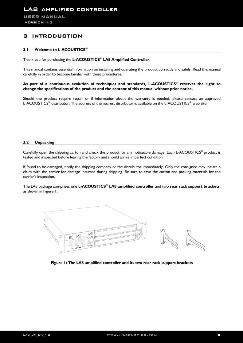
Carefully open the shipping carton and check the product for any noticeable damage. Each L-ACOUSTICS® product is tested and inspected before leaving the factory and should arrive in perfect condition. If found to be damaged, notify the shipping company or the distributor immediately. Only the consignee may initiate a claim with the carrier for damage incurred during shipping. Be sure to save the carton and packing materials for the carrier's inspection. The LA8 package comprises one L-ACOUSTICS® LA8 amplified controller and two rear rack support brackets, as shown in Figure 1:
Figure 1: The LA8 amplified controller and its two rear rack support brackets
LA8_UM_EN_4-0 www . l - a co ust i c s . c o m 9999
3.3 Cross-references
All along the manual, a bracketed number refers to a section. For example, [3.3] stands for the present section: Cross-references. 3.4 Web links
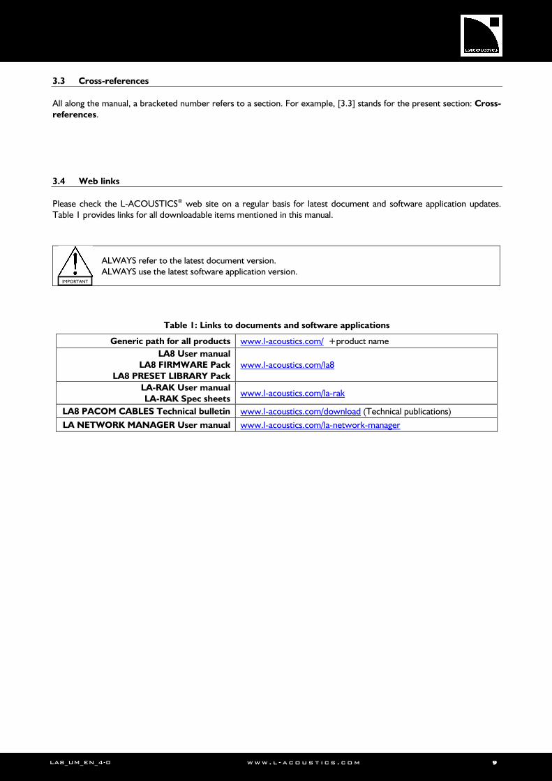
Please check the L-ACOUSTICS® web site on a regular basis for latest document and software application updates. Table 1 provides links for all downloadable items mentioned in this manual.
ALWAYS refer to the latest document version. ALWAYS use the latest software application version.
Table 1: Links to documents and software applications
Generic path for all products www.l-acoustics.com/ +product name LA8 User manual
LA8 FIRMWARE Pack
LA8 PRESET LIBRARY Pack
www.l-acoustics.com/la8
LA-RAK User manual
LA-RAK Spec sheets www.l-acoustics.com/la-rak
LA8 PACOM CABLES Technical bulletin www.l-acoustics.com/download (Technical publications)
LA NETWORK MANAGER User manual www.l-acoustics.com/la-network-manager
IMPORTANT

LALALALA8888 AMPLIFIED CONTROLLERAMPLIFIED CONTROLLERAMPLIFIED CONTROLLERAMPLIFIED CONTROLLER USER MANUALUSER MANUALUSER MANUALUSER MANUAL VERSION 4.0
LA8_UM_EN_4-0 www . l - a co ust i c s . c o m 10101010
4444 COMPLETE COMPLETE COMPLETE COMPLETE SYSTEM APPROACHSYSTEM APPROACHSYSTEM APPROACHSYSTEM APPROACH
4.1 LA8 Presentation
At the heart of the L-ACOUSTICS® complete system approach, the LA4 and LA8 amplified controllers offer high performance loudspeaker amplification, DSP, network control, and comprehensive system protection in a single ergonomic 2U package. Based upon similar platforms, the exceptional and ground breaking performance level delivered by both the LA4 and LA8 allow for full optimization of all L-ACOUSTICS® system resources and deliver outstanding audio quality combined with the best possible transducer protection.
Both the LA4 and LA8 share the following characteristics:
• A four-channel high efficiency amplifier section fed by two inputs, offering a power level matching for all L-ACOUSTICS® loudspeaker systems
• A DSP section featuring advanced filter algorithms and an exclusive L-DRIVE protection system for the transducers allowing for optimum system performance
• A complete on board PRESET LIBRARY developed for immediate use with a minimum of EQ correction, optimized system resources and a unique sonic signature for all systems, and 10 user memory locations.
• An intuitive and ergonomic user interface, fully accessible from the front panel for standalone operation
• Two I/O Ethernet ports for networking up to 253 units
• The complementary LA NETWORK MANAGER Windows® software with remote monitoring and control of all LA4 and LA8 units of the network
Specific features of the LA8 include:
• Up to 4 x 1800 Watts into 4 ohms
• An integrated LA-AES3 AES/EBU board for digital audio input
• Two 4-point SpeakON® and one 8-pin CA-COM® connectors for loudspeaker outputs
4.2 Loudspeaker system configurations
Driving four amplifier output channels through a DSP offers a wide range of options when it comes to sound system configuration possibilities. The LA4 and LA8 onboard DSP preset libraries allow the Sound Engineer a high degree of flexibility through the use of the 6 following configurations:
• 4-way active mono system.
• 2-channel stereo system (for subwoofers or passive enclosures).
• 2-way active stereo system.
• Hybrid mono system (for subwoofers and active enclosures).
• Hybrid stereo system (for subwoofers and passive enclosures).
• Cardioid mono subwoofer system.
4.3 System components related to the LA8
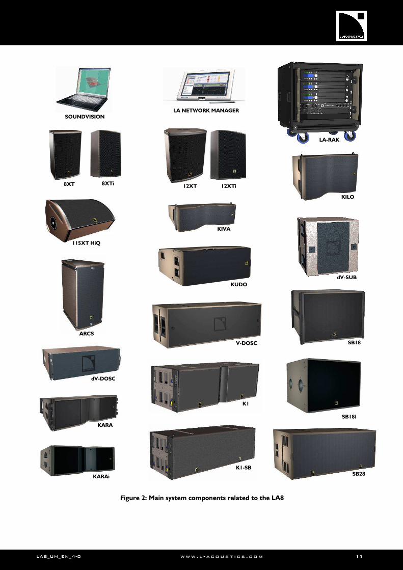
The complete system approach developed by L-ACOUSTICS® consists in providing all the components needed to offer the highest, most predictable level of performance. Here are the main components that can be used when setting an L-ACOUSTICS® complete system with LA8 (see Figure 2):
8XT, 8XTi, 12XT, 12XTi, 115XT HiQ 2-way coaxial enclosures
KIVA, KARA®, KARAi®, dV-DOSC, ARCS® 2-way WST® enclosures
K1, KUDO®, V-DOSC® 3-way WST® enclosures
K1-SB, dV-SUB Subwoofer extensions for K1 and dV-DOSC, respectively
SB18, SB18i, SB28 Subwoofer enclosures
LA-RAK Touring rack containing three LA8 amplified controllers
LA NETWORK MANAGER Remote control software for a network of controllers
SOUNDVISION Acoustical and mechanical 3D modeling software
A complete L-ACOUSTICS®
system also features standard L-ACOUSTICS® cables and rigging accessories. For more details refer to the appropriate manuals [3.4].
LA8_UM_EN_4-0 www . l - a co ust i c s . c o m 11111111
Figure 2: Main system components related to the LA8
LA NETWORK MANAGER SOUNDVISION
LA-RAK
V-DOSC
KUDO
K1
K1-SB
ARCS
SB18
SB28
dV-SUB
SB18i
dV-DOSC
KARA
KARAi
115XT HiQ
12XT 12XTi 8XT 8XTi
KIVA
KILO
LALALALA8888 AMPLIFIED CONTROLLERAMPLIFIED CONTROLLERAMPLIFIED CONTROLLERAMPLIFIED CONTROLLER USER MANUALUSER MANUALUSER MANUALUSER MANUAL VERSION 4.0
LA8_UM_EN_4-0 www . l - a co ust i c s . c o m 12121212
5555 LA8 AMPLIFIED CONTROLLERLA8 AMPLIFIED CONTROLLERLA8 AMPLIFIED CONTROLLERLA8 AMPLIFIED CONTROLLER
5.1 Main features
5.1.1 Front and rear panel
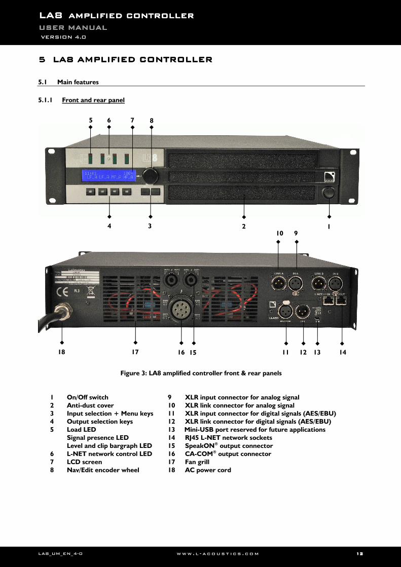
Figure 3: LA8 amplified controller front & rear panels
1 On/Off switch
2 Anti-dust cover
3 Input selection + Menu keys 4 Output selection keys
5 Load LED
Signal presence LED
Level and clip bargraph LED
6 L-NET network control LED
7 LCD screen
8 Nav/Edit encoder wheel
9 XLR input connector for analog signal
10 XLR link connector for analog signal
11 XLR input connector for digital signals (AES/EBU) 12 XLR link connector for digital signals (AES/EBU)
13 Mini-USB port reserved for future applications
14 RJ45 L-NET network sockets
15 SpeakON® output connector
16 CA-COM® output connector
17 Fan grill
18 AC power cord
4 3 2 1
18 17 16
10 9
11 14 13 12 15
5 6 7 8
LA8_UM_EN_4-0 www . l - a co ust i c s . c o m 13131313
5.1.2 Simplified block diagram
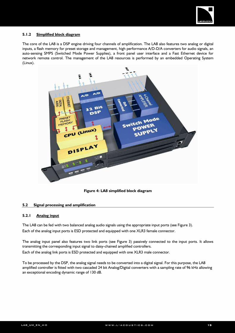
The core of the LA8 is a DSP engine driving four channels of amplification. The LA8 also features two analog or digital inputs, a flash memory for preset storage and management, high performance A/D-D/A converters for audio signals, an auto-sensing SMPS (Switched Mode Power Supplies), a front panel user interface and a Fast Ethernet device for network remote control. The management of the LA8 resources is performed by an embedded Operating System (Linux).
Figure 4: LA8 simplified block diagram
5.2 Signal processing and amplification
5.2.1 Analog input
The LA8 can be fed with two balanced analog audio signals using the appropriate input ports (see Figure 3).
Each of the analog input ports is ESD protected and equipped with one XLR3 female connector.
The analog input panel also features two link ports (see Figure 3) passively connected to the input ports. It allows transmitting the corresponding input signal to daisy-chained amplified controllers.
Each of the analog link ports is ESD protected and equipped with one XLR3 male connector.
To be processed by the DSP, the analog signal needs to be converted into a digital signal. For this purpose, the LA8 amplified controller is fitted with two cascaded 24 bit Analog/Digital converters with a sampling rate of 96 kHz allowing an exceptional encoding dynamic range of 130 dB.
LALALALA8888 AMPLIFIED CONTROLLERAMPLIFIED CONTROLLERAMPLIFIED CONTROLLERAMPLIFIED CONTROLLER USER MANUALUSER MANUALUSER MANUALUSER MANUAL VERSION 4.0
LA8_UM_EN_4-0 www . l - a co ust i c s . c o m 14141414
5.2.2 AES/EBU digital input
The LA8 can be fed with one AES/EBU digital audio signal carrying two audio channels, thanks to the LA-AES3 board.
This one offers one input port, one active link port (see Figure 3) and a Sample Rate Converter (SRC).
The AES/EBU input port is ESD protected and equipped with one XLR3 female connector (transformer balanced). It allows the LA8 to receive two digital audio channels coming from a digital mixing desk or a digital audio network bridge compliant with the AES/EBU (AES3) or coaxial S/PDIF (IEC 60958 Type II) digital audio standards. The AES/EBU link port is ESD protected and equipped with one XLR3 male connector (transformer balanced). It allows transmitting the input signal to daisy-chained amplified controllers. The SRC embedded in the LA-AES3 board has been selected to support a wide range of input formats (16-24 bits/ 44.1-192 kHz). It converts any of them to the 24 bits/96 kHz internal format used by the amplified controller. The SRC is a high-quality hardware component (140 dB dynamic range, THD+N<-120 dBfs, strong input jitter attenuation) and provides constant propagation delay regardless of the input sampling frequency. There is no external synchronization mode. The amplified controller’s clock always runs using its high-precision internal quartz at 96 kHz. It ensures low jitter and high audio quality while preserving isophase required for line source systems.
Note: Keeping the signal in the digital domain by using the LA-AES3 board will provide the following benefits (with any digital mixing desk or any audio network) compared to the analog signal distribution:
• Better audio quality by removing one Analog/Digital conversion cycle.
• Better dynamics thanks to the digital links’ immunity to ground loops.
• Optimized level chain by removing the risk of level misalignment between console and amplified controllers.
• Possibility to reduce the amplified controller propagation delay by 0.5 ms.
• Digital signal refreshed at each amplified controller in a daisy-chain.
• Improved maximum cable length. The LA-AES3 has been tested with up to 305 m/1000 ft of 3 types of AES/EBU rated cables: BELDEN® 1696A, KLOTZ a.i.s.® OT234H, and SOMMER Cable® SC BINARY 234 (single cuts, digital source signal running at Fs = 48 kHz).
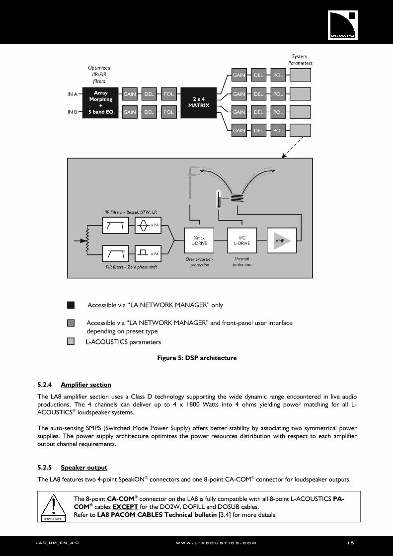
5.2.3 DSP architecture
The proprietary algorithms allows optimum performance and protection of each individual transducer of the L-ACOUSTICS® system in use for an even more natural, transparent, and realistic sound experience.
• The DSP engine is a SHARC 32 bit floating point DSP at 96 kHz sampling rate. Compared to fixed point DSP, it offers enhanced dynamic range and precision, allowing much better headroom and signal-to-quantification-noise ratio.
• A special engineering approach combining IIR and FIR filters generates a perfect linearization of phase curves and therefore a significant improvement of the system impulse response.
• The 2 x 4 matrix architecture offers flexibility for various system configurations.
• The L-DRIVE transducer protection system offers advanced protection by regulating both excursion and temperature of the transducer [10.2].
• The flash memory offers a quick access to 89 factory presets and 10 user memory locations, allowing the user to deal with all the usual L-ACOUSTICS® speaker system configurations (refer to the LA4-8 PRESET
LIBRARIES User manual included in the LA8 PRESET LIBRARY Pack [3.4]).
LA8_UM_EN_4-0 www . l - a co ust i c s . c o m 15151515
Figure 5: DSP architecture
5.2.4 Amplifier section
The LA8 amplifier section uses a Class D technology supporting the wide dynamic range encountered in live audio productions. The 4 channels can deliver up to 4 x 1800 Watts into 4 ohms yielding power matching for all L-ACOUSTICS® loudspeaker systems. The auto-sensing SMPS (Switched Mode Power Supply) offers better stability by associating two symmetrical power supplies. The power supply architecture optimizes the power resources distribution with respect to each amplifier output channel requirements. 5.2.5 Speaker output
The LA8 features two 4-point SpeakON® connectors and one 8-point CA-COM® connector for loudspeaker outputs.
The 8-point CA-COM® connector on the LA8 is fully compatible with all 8-point L-ACOUSTICS PA-
COM® cables EXCEPT for the DO2W, DOFILL and DOSUB cables. Refer to LA8 PACOM CABLES Technical bulletin [3.4] for more details.
IMPORTANT
2 x 4 MATRIX
Array Morphing
+ 5 band EQ
LALALALA8888 AMPLIFIED CONTROLLERAMPLIFIED CONTROLLERAMPLIFIED CONTROLLERAMPLIFIED CONTROLLER USER MANUALUSER MANUALUSER MANUALUSER MANUAL VERSION 4.0
LA8_UM_EN_4-0 www . l - a co ust i c s . c o m 16161616
5.3 Monitoring and control
5.3.1 User interface
LED display allows real time monitoring of signals presence and level. LCD display offers quick visualization of the system parameters. The front panel user interface features quick access functions for the 2 inputs and 4 outputs. The encoder wheel gives fast and intuitive access to navigation and parameters selection. Note: Please refer to [7] for detailed operating instructions 5.3.2 L-NET Remote Control Network
The proprietary L-NET network uses a high speed data transfer of 100 Mbit/sec for real time monitoring and control of each individual LA controller within a network of up to 253 units. Multiple network topologies such as daisy-chain, star, and hybrid are quickly and easily configurable with total flexibility in achieving the required system architecture. The physical connection between the computer and the controllers is managed with CAT5e U/FTP cables (or higher category) and the I/O Ethernet sockets located on the rear panel of the controller require industry standard RJ45 connectors. The use of a universal Ethernet switch is recommended for specific network topologies. Note: Please refer to the LA NETWORK MANAGER User manual [3.4] for detailed operating instructions.
5.3.3 LA NETWORK MANAGER Software
L-ACOUSTICS® LA NETWORK MANAGER provides network control and monitoring of both LA4 and LA8 controllers from a computer running a Windows® operating system. The multiple window display gives an overall visualization of the network status, number and groups of controllers, and all the information related to the control and monitoring of the networked controllers. Real-time access to all settings such as input mode, preset, mute/solo, gain, delay, polarity, and matrix can be done using the remote software interface. A contour EQ system is also available for quick and easy loudspeaker system frequency response setting, including the unique L-ACOUSTICS® Array Morphing tool dedicated to line source array systems. LA NETWORK MANAGER also features system stand-by and initialization control in addition to comprehensive visual monitoring of the audio signal paths and quick detection of any faults on the amplified controllers connected to the network. Note: Please refer to the LA NETWORK MANAGER User manual [3.4] for detailed operating instructions.
LA8_UM_EN_4-0 www . l - a co ust i c s . c o m 17171717
6666 INSTALLATIONINSTALLATIONINSTALLATIONINSTALLATION
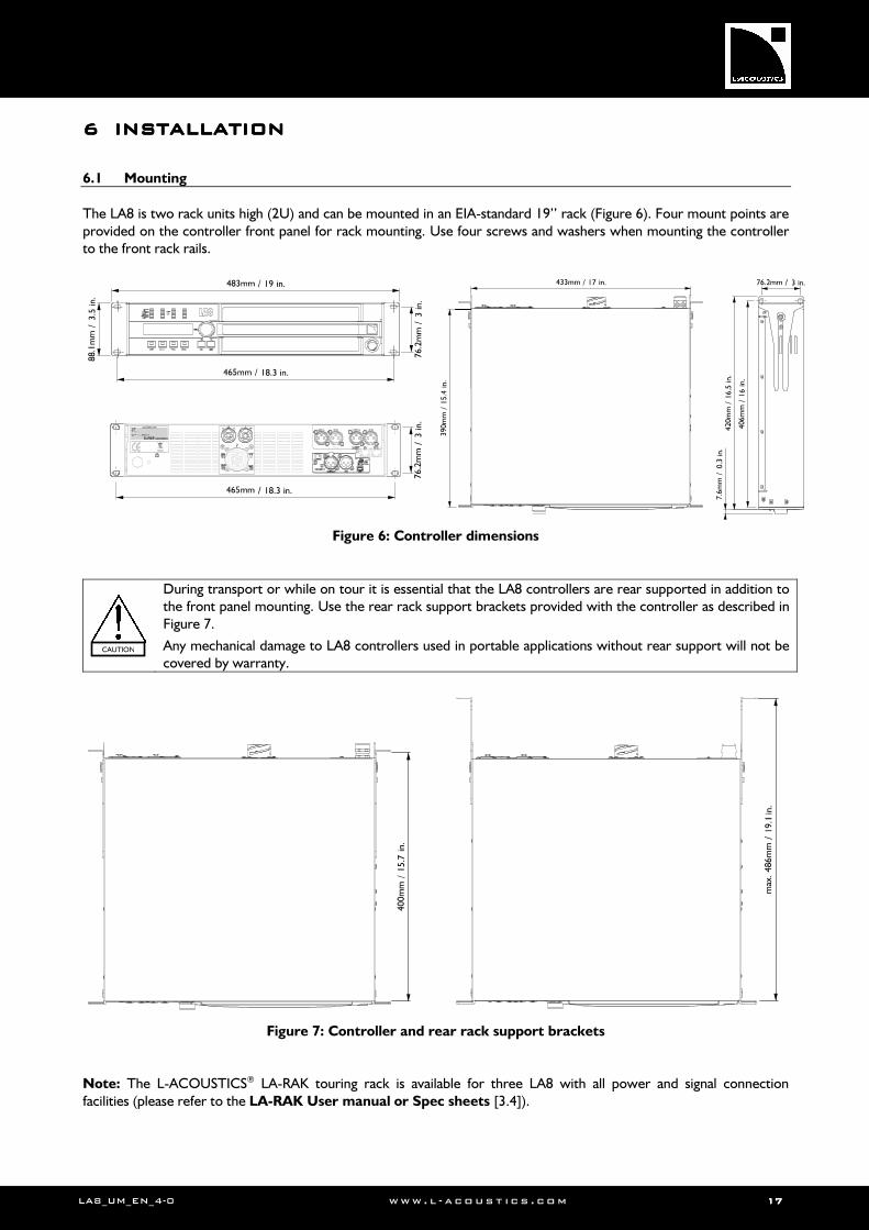
6.1 Mounting
The LA8 is two rack units high (2U) and can be mounted in an EIA-standard 19’’ rack (Figure 6). Four mount points are provided on the controller front panel for rack mounting. Use four screws and washers when mounting the controller to the front rack rails.
Figure 6: Controller dimensions
During transport or while on tour it is essential that the LA8 controllers are rear supported in addition to the front panel mounting. Use the rear rack support brackets provided with the controller as described in Figure 7.
Any mechanical damage to LA8 controllers used in portable applications without rear support will not be covered by warranty.
Figure 7: Controller and rear rack support brackets
Note: The L-ACOUSTICS® LA-RAK touring rack is available for three LA8 with all power and signal connection facilities (please refer to the LA-RAK User manual or Spec sheets [3.4]).
CAUTION
LALALALA8888 AMPLIFIED CONTROLLERAMPLIFIED CONTROLLERAMPLIFIED CONTROLLERAMPLIFIED CONTROLLER USER MANUALUSER MANUALUSER MANUALUSER MANUAL VERSION 4.0
LA8_UM_EN_4-0 www . l - a co ust i c s . c o m 18181818
6.2 Cooling
The amplified controller uses a forced air cooling system to maintain a low and even operating temperature. All fan cooled L-ACOUSTICS® amplified controllers have front to rear airflow. Therefore when stacking more than one unit in a rack, mount units directly on top of each other or close any open space in the rack with blank panels.
If the controller is rack-mounted do not block front or rear air vents with front or back panels or doors. If this cannot be achieved a forced ventilation system has to be used.
If the controller is installed in an enclosed rack the open area at the back of the controller must be at least 140 cm3 per controller.
Ensure that the front filter system is clean and dust free [8.1].
6.3 Connecting to AC mains
6.3.1 Operating voltage
Operating voltage range and frequency are indicated on the controller back panel.
Only connect the controller to an appropriate AC circuit and outlet.
If the output voltage of the AC mains is unsure consult an electrician.
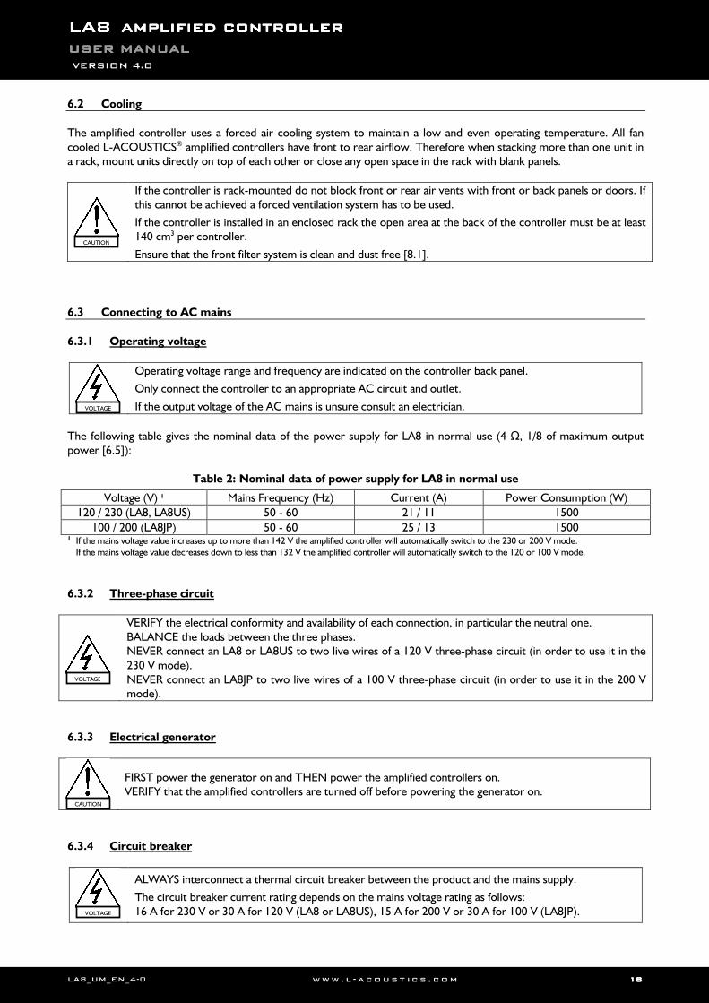
The following table gives the nominal data of the power supply for LA8 in normal use (4 Ω, 1/8 of maximum output power [6.5]):
Table 2: Nominal data of power supply for LA8 in normal use
Voltage (V) 1 Mains Frequency (Hz) Current (A) Power Consumption (W)
120 / 230 (LA8, LA8US) 50 - 60 21 / 11 1500
100 / 200 (LA8JP) 50 - 60 25 / 13 1500 1 If the mains voltage value increases up to more than 142 V the amplified controller will automatically switch to the 230 or 200 V mode.
If the mains voltage value decreases down to less than 132 V the amplified controller will automatically switch to the 120 or 100 V mode.
6.3.2 Three-phase circuit
VERIFY the electrical conformity and availability of each connection, in particular the neutral one. BALANCE the loads between the three phases. NEVER connect an LA8 or LA8US to two live wires of a 120 V three-phase circuit (in order to use it in the 230 V mode). NEVER connect an LA8JP to two live wires of a 100 V three-phase circuit (in order to use it in the 200 V mode).
6.3.3 Electrical generator
FIRST power the generator on and THEN power the amplified controllers on. VERIFY that the amplified controllers are turned off before powering the generator on.
6.3.4 Circuit breaker
ALWAYS interconnect a thermal circuit breaker between the product and the mains supply.
The circuit breaker current rating depends on the mains voltage rating as follows: 16 A for 230 V or 30 A for 120 V (LA8 or LA8US), 15 A for 200 V or 30 A for 100 V (LA8JP).
CAUTION
VOLTAGE
VOLTAGE
VOLTAGE
CAUTION
LA8_UM_EN_4-0 www . l - a co ust i c s . c o m 19191919
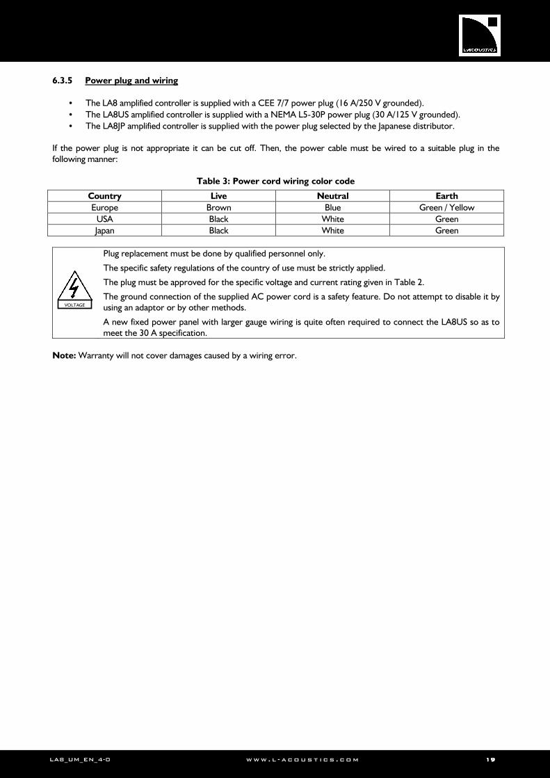
6.3.5 Power plug and wiring
• The LA8 amplified controller is supplied with a CEE 7/7 power plug (16 A/250 V grounded).
• The LA8US amplified controller is supplied with a NEMA L5-30P power plug (30 A/125 V grounded).
• The LA8JP amplified controller is supplied with the power plug selected by the Japanese distributor. If the power plug is not appropriate it can be cut off. Then, the power cable must be wired to a suitable plug in the following manner:
Table 3: Power cord wiring color code
Country Live Neutral Earth
Europe Brown Blue Green / Yellow
USA Black White Green
Japan Black White Green
Plug replacement must be done by qualified personnel only.
The specific safety regulations of the country of use must be strictly applied.
The plug must be approved for the specific voltage and current rating given in Table 2.
The ground connection of the supplied AC power cord is a safety feature. Do not attempt to disable it by using an adaptor or by other methods.
A new fixed power panel with larger gauge wiring is quite often required to connect the LA8US so as to meet the 30 A specification.
Note: Warranty will not cover damages caused by a wiring error.
VOLTAGE
LALALALA8888 AMPLIFIED CONTROLLERAMPLIFIED CONTROLLERAMPLIFIED CONTROLLERAMPLIFIED CONTROLLER USER MANUALUSER MANUALUSER MANUALUSER MANUAL VERSION 4.0
LA8_UM_EN_4-0 www . l - a co ust i c s . c o m 20202020
6.4 Audio and network cabling
6.4.1 Connection panels
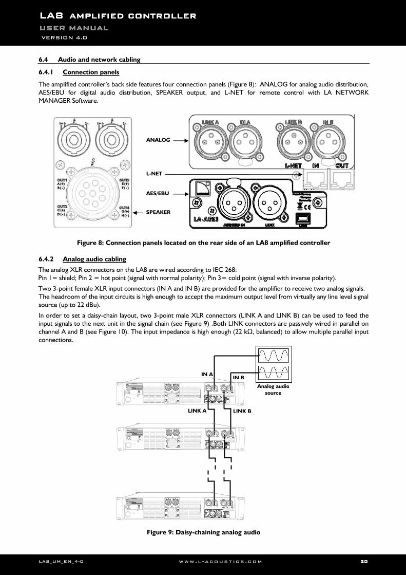
The amplified controller’s back side features four connection panels (Figure 8): ANALOG for analog audio distribution, AES/EBU for digital audio distribution, SPEAKER output, and L-NET for remote control with LA NETWORK MANAGER Software.
Figure 8: Connection panels located on the rear side of an LA8 amplified controller
6.4.2 Analog audio cabling
The analog XLR connectors on the LA8 are wired according to IEC 268: Pin 1= shield; Pin 2 = hot point (signal with normal polarity); Pin 3= cold point (signal with inverse polarity).
Two 3-point female XLR input connectors (IN A and IN B) are provided for the amplifier to receive two analog signals. The headroom of the input circuits is high enough to accept the maximum output level from virtually any line level signal source (up to 22 dBu).
In order to set a daisy-chain layout, two 3-point male XLR connectors (LINK A and LINK B) can be used to feed the input signals to the next unit in the signal chain (see Figure 9) .Both LINK connectors are passively wired in parallel on channel A and B (see Figure 10). The input impedance is high enough (22 kΩ, balanced) to allow multiple parallel input connections.
Figure 9: Daisy-chaining analog audio
ANALOG
L-NET
AES/EBU
SPEAKER
IN A
LINK A
IN B
LINK B
Analog audio
source
LA8_UM_EN_4-0 www . l - a co ust i c s . c o m 21212121
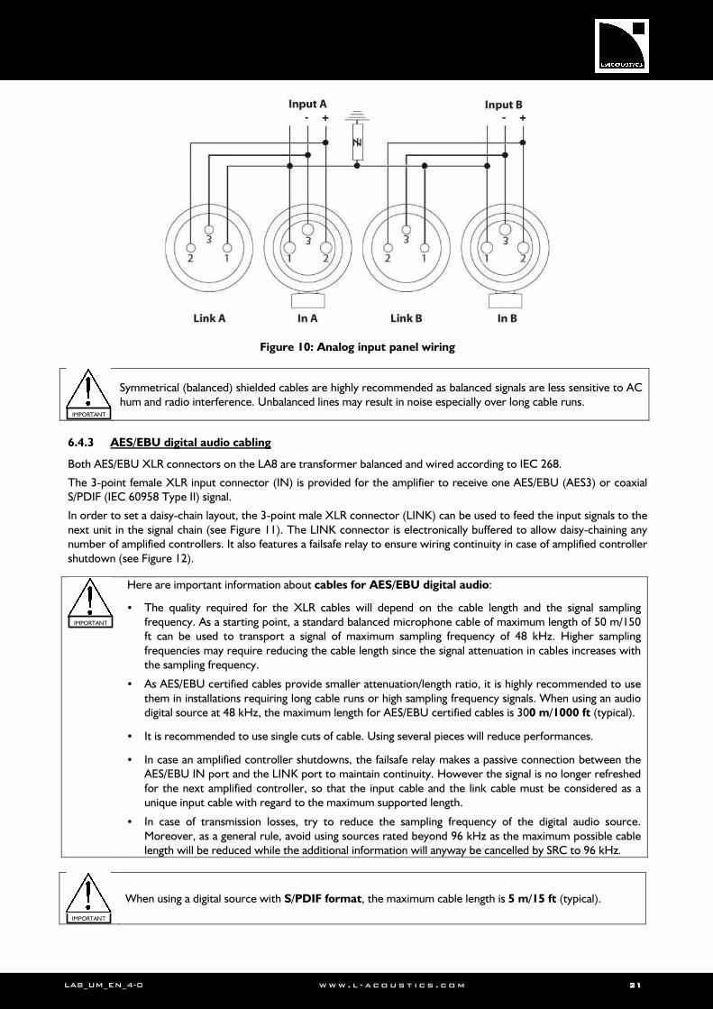
Figure 10: Analog input panel wiring
Symmetrical (balanced) shielded cables are highly recommended as balanced signals are less sensitive to AC hum and radio interference. Unbalanced lines may result in noise especially over long cable runs.
6.4.3 AES/EBU digital audio cabling
Both AES/EBU XLR connectors on the LA8 are transformer balanced and wired according to IEC 268.
The 3-point female XLR input connector (IN) is provided for the amplifier to receive one AES/EBU (AES3) or coaxial S/PDIF (IEC 60958 Type II) signal.
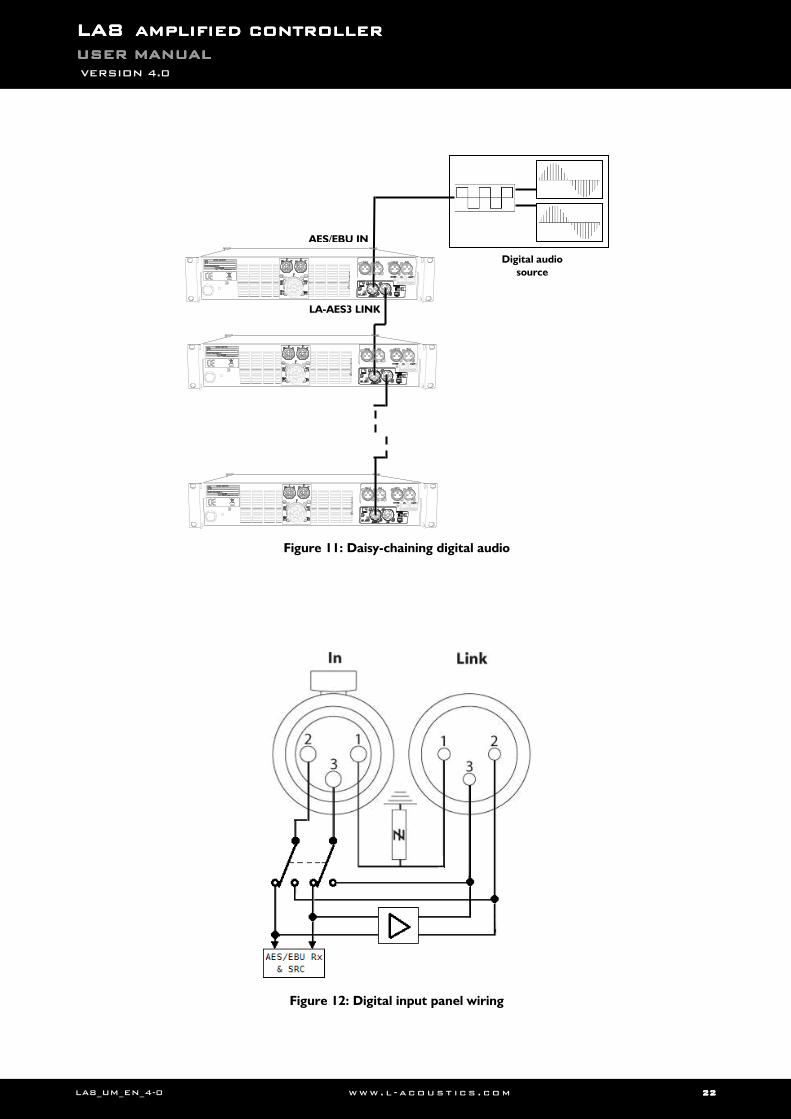
In order to set a daisy-chain layout, the 3-point male XLR connector (LINK) can be used to feed the input signals to the next unit in the signal chain (see Figure 11). The LINK connector is electronically buffered to allow daisy-chaining any number of amplified controllers. It also features a failsafe relay to ensure wiring continuity in case of amplified controller shutdown (see Figure 12).
Here are important information about cables for AES/EBU digital audio:
• The quality required for the XLR cables will depend on the cable length and the signal sampling frequency. As a starting point, a standard balanced microphone cable of maximum length of 50 m/150 ft can be used to transport a signal of maximum sampling frequency of 48 kHz. Higher sampling frequencies may require reducing the cable length since the signal attenuation in cables increases with the sampling frequency.
• As AES/EBU certified cables provide smaller attenuation/length ratio, it is highly recommended to use them in installations requiring long cable runs or high sampling frequency signals. When using an audio digital source at 48 kHz, the maximum length for AES/EBU certified cables is 300 m/1000 ft (typical).
• It is recommended to use single cuts of cable. Using several pieces will reduce performances.
• In case an amplified controller shutdowns, the failsafe relay makes a passive connection between the AES/EBU IN port and the LINK port to maintain continuity. However the signal is no longer refreshed for the next amplified controller, so that the input cable and the link cable must be considered as a unique input cable with regard to the maximum supported length.
• In case of transmission losses, try to reduce the sampling frequency of the digital audio source. Moreover, as a general rule, avoid using sources rated beyond 96 kHz as the maximum possible cable length will be reduced while the additional information will anyway be cancelled by SRC to 96 kHz.
When using a digital source with S/PDIF format, the maximum cable length is 5 m/15 ft (typical).
IMPORTANT
IMPORTANT
IMPORTANT
LALALALA8888 AMPLIFIED CONTROLLERAMPLIFIED CONTROLLERAMPLIFIED CONTROLLERAMPLIFIED CONTROLLER USER MANUALUSER MANUALUSER MANUALUSER MANUAL VERSION 4.0
LA8_UM_EN_4-0 www . l - a co ust i c s . c o m 22222222
Figure 11: Daisy-chaining digital audio
Figure 12: Digital input panel wiring
AES/EBU IN
LA-AES3 LINK
Digital audio
source
LA8_UM_EN_4-0 www . l - a co ust i c s . c o m 23232323
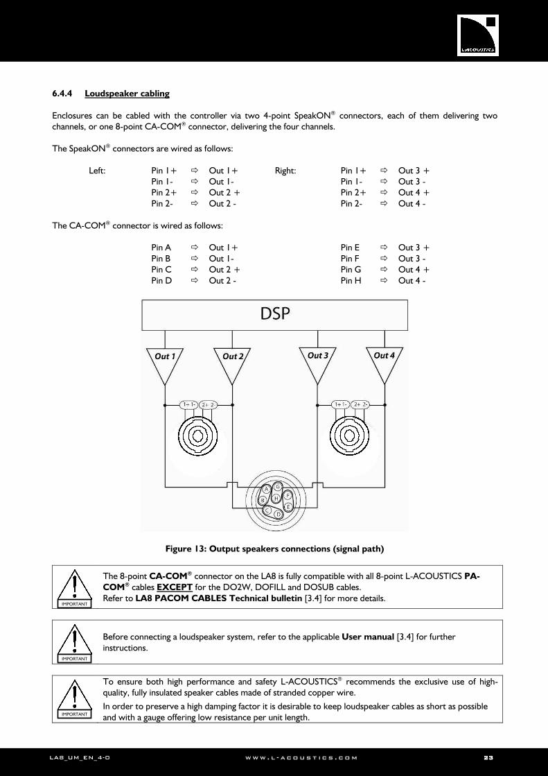
6.4.4 Loudspeaker cabling
Enclosures can be cabled with the controller via two 4-point SpeakON® connectors, each of them delivering two channels, or one 8-point CA-COM® connector, delivering the four channels. The SpeakON® connectors are wired as follows:
Left: Pin 1+ Out 1+ Pin 1- Out 1- Pin 2+ Out 2 + Pin 2- Out 2 -
Right: Pin 1+ Out 3 + Pin 1- Out 3 - Pin 2+ Out 4 + Pin 2- Out 4 -
The CA-COM® connector is wired as follows:
Pin A Out 1+ Pin B Out 1- Pin C Out 2 + Pin D Out 2 -
Pin E Out 3 + Pin F Out 3 - Pin G Out 4 + Pin H Out 4 -
Figure 13: Output speakers connections (signal path)
The 8-point CA-COM® connector on the LA8 is fully compatible with all 8-point L-ACOUSTICS PA-
COM® cables EXCEPT for the DO2W, DOFILL and DOSUB cables. Refer to LA8 PACOM CABLES Technical bulletin [3.4] for more details.
Before connecting a loudspeaker system, refer to the applicable User manual [3.4] for further instructions.
To ensure both high performance and safety L-ACOUSTICS® recommends the exclusive use of high-quality, fully insulated speaker cables made of stranded copper wire.
In order to preserve a high damping factor it is desirable to keep loudspeaker cables as short as possible and with a gauge offering low resistance per unit length.
IMPORTANT
IMPORTANT
IMPORTANT
LALALALA8888 AMPLIFIED CONTROLLERAMPLIFIED CONTROLLERAMPLIFIED CONTROLLERAMPLIFIED CONTROLLER USER MANUALUSER MANUALUSER MANUALUSER MANUAL VERSION 4.0
LA8_UM_EN_4-0 www . l - a co ust i c s . c o m 24242424
6.4.5 L-NET network cabling
The LA8 can be connected to a network of several controllers driven by a computer running LA NETWORK MANAGER Software (refer to the LA NETWORK MANAGER User manual [3.4]). The connection is done using the I/O Ethernet RJ45 sockets located on the LA8 rear panel (see Figure 8).
Connect the computer and amplified controllers to the network using straight-through Ethernet cables of CAT5e U/FTP category (or higher) and of 100 m/328 ft maximum length.
Exception: If the Auto MDI/MDIX functionality is NOT available on a switch used to build a star or hybrid topology, use a crossover cable between the switch and each controller.
Notes:
• The L-NET Network is rated at 100 Mbps.
• A straight-through cable has pin 1 of one side connected to pin 1 of the other side, pin 2 to pin 2… A crossover cable has 1-2 and 3-6 pin pairs crossed (it can be seen directly on the cable by comparing the wire colors between both RJ45 connectors).
• CAT5e U/FTP stands for a category 5, unshielded cable with foiled twisted pairs. Using lower category cables or CAT5e “patch” cables will result in connection issues.
• The maximum length for a typical CAT5e U/FTP cable is 100m/328ft. This value is indicative and can vary depending on the quality of the cable.
6.5 Power consumption
The LA8 power requirements summarized in Table 4 (4 channels being driven at the same time) are dependent of load impedance and signal level characteristics:
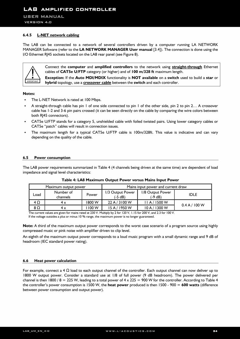
Table 4: LA8 Maximum Output Power versus Mains Input Power
Maximum output power Mains input power and current draw
Load Number of
channels Power
1/3 Output Power (-5 dB)
1/8 Output Power (-9 dB)
IDLE
4 Ω 4 x 1800 W 22 A / 3100 W 11 A / 1500 W 0.4 A / 100 W
8 Ω 4 x 1100 W 15 A / 1950 W 10 A / 1300 W The current values are given for mains rated at 230 V. Multiply by 2 for 120 V, 1.15 for 200 V, and 2.3 for 100 V. If the voltage outsides a plus or minus 10 % range, the maximum power is no longer guaranteed.
Note: A third of the maximum output power corresponds to the worst case scenario of a program source using highly compressed music or pink noise with amplifier driven to clip level.
An eighth of the maximum output power corresponds to a loud music program with a small dynamic range and 9 dB of headroom (IEC standard power rating).
6.6 Heat power calculation
For example, connect a 4 Ω load to each output channel of the controller. Each output channel can now deliver up to 1800 W output power. Consider a standard use at 1/8 of full power (9 dB headroom). The power delivered per channel is then 1800 / 8 = 225 W, leading to a total power of 4 x 225 = 900 W for the controller. According to Table 4 the controller’s power consumption is 1500 W, the heat power produced is then 1500 - 900 = 600 watts (difference between power consumption and output power).
IMPORTANT

LA8_UM_EN_4-0 www . l - a co ust i c s . c o m 25252525
7777 OPERATIONOPERATIONOPERATIONOPERATION
7.1 On/Off switch
When switched on (Figure 14), the controller goes through a 25-second start-up sequence, displaying an empty screen followed by the messages below. The controller is ready for use when the LCD displays the main screen [7.2.1].
Testing sequence with all LED momentarily lit.
FIRMWARE version display.
When switched off, the controller goes through a shutdown sequence coming with the following message:
Message displayed for several seconds with LOAD LED lit until complete shutdown.
If the controller is switched on again while this message is displayed, the controller will recover the operating state without going through the start-up sequence (the AMP
running message will be displayed).
Figure 14: The On/Off switch
If a power loss occurs for less than 10 seconds while the controller is on and no signal is passing through the amp, the controller will remain on and will not shut down.
If the power has been lost for more than 10 seconds, the controller will shut down but all parameters will be restored to same state as before shutting down when the controller switches on again.
The On/Off switch does NOT disconnect the amplified controller from mains.
Note: The controller can be put in standby mode from LA NETWORK MANAGER Software to prevent any front panel control and reduce electrical consumption (refer to the LA NETWORK MANAGER User manual [3.4]). In this case, the following message will be displayed while the controller is in standby mode:
Message displayed with LOAD LED lit.
Note: By restarting the unit (switching it off and on again), it is possible to cancel the standby mode and LA NETWORK MANAGER exclusive control.
IMPORTANT
On Off
System Message Standby Mode
System Message Waiting SMPS
Initializing Controller
L-ACOUSTICS LA8 FIRMWARE VERSION 1.4.1
VOLTAGE
LALALALA8888 AMPLIFIED CONTROLLERAMPLIFIED CONTROLLERAMPLIFIED CONTROLLERAMPLIFIED CONTROLLER USER MANUALUSER MANUALUSER MANUALUSER MANUAL VERSION 4.0
LA8_UM_EN_4-0 www . l - a co ust i c s . c o m 26262626
7.2 Display
7.2.1 Main screen
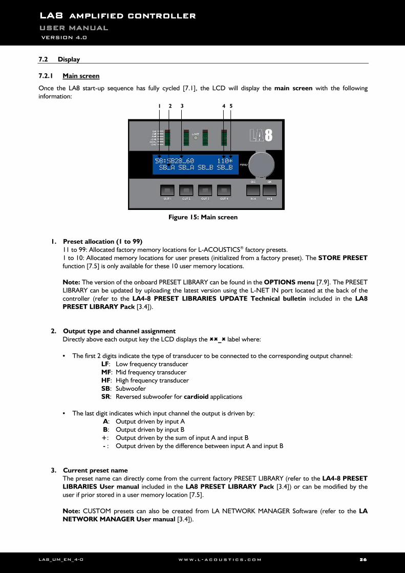
Once the LA8 start-up sequence has fully cycled [7.1], the LCD will display the main screen with the following information:
Figure 15: Main screen
1. Preset allocation (1 to 99) 11 to 99: Allocated factory memory locations for L-ACOUSTICS® factory presets. 1 to 10: Allocated memory locations for user presets (initialized from a factory preset). The STORE PRESET function [7.5] is only available for these 10 user memory locations.
Note: The version of the onboard PRESET LIBRARY can be found in the OPTIONS menu [7.9]. The PRESET LIBRARY can be updated by uploading the latest version using the L-NET IN port located at the back of the controller (refer to the LA4-8 PRESET LIBRARIES UPDATE Technical bulletin included in the LA8
PRESET LIBRARY Pack [3.4]).
2. Output type and channel assignment
Directly above each output key the LCD displays the _ label where:
• The first 2 digits indicate the type of transducer to be connected to the corresponding output channel: LF: Low frequency transducer MF: Mid frequency transducer HF: High frequency transducer SB: Subwoofer SR: Reversed subwoofer for cardioid applications
• The last digit indicates which input channel the output is driven by: A: Output driven by input A B: Output driven by input B +: Output driven by the sum of input A and input B - : Output driven by the difference between input A and input B
3. Current preset name The preset name can directly come from the current factory PRESET LIBRARY (refer to the LA4-8 PRESET LIBRARIES User manual included in the LA8 PRESET LIBRARY Pack [3.4]) or can be modified by the user if prior stored in a user memory location [7.5]. Note: CUSTOM presets can also be created from LA NETWORK MANAGER Software (refer to the LA
NETWORK MANAGER User manual [3.4]).
1 2 3 4 5
LA8_UM_EN_4-0 www . l - a co ust i c s . c o m 27272727
4. Last number in the IP address (1 to 253)
The last number in the IP address identifies the current controller within a network of multiple LA4 and/or LA8 units. IP address description and setting are detailed in the OPTIONS menu [7.9].
5. Star sign (*) The star sign is displayed when parameter settings have been modified from the original preset stored in memory.
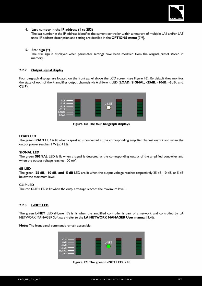
7.2.2 Output signal display
Four bargraph displays are located on the front panel above the LCD screen (see Figure 16). By default they monitor the state of each of the 4 amplifier output channels via 6 different LED (LOAD, SIGNAL, -25dB, -10dB, -5dB, and
CLIP).
Figure 16: The four bargraph displays
LOAD LED
The green LOAD LED is lit when a speaker is connected at the corresponding amplifier channel output and when the output power reaches 1 W (at 4 Ω). SIGNAL LED
The green SIGNAL LED is lit when a signal is detected at the corresponding output of the amplified controller and when the output voltage reaches 100 mV. dB LED
The green -25 dB, -10 dB, and -5 dB LED are lit when the output voltage reaches respectively 25 dB, 10 dB, or 5 dB below the maximum level. CLIP LED
The red CLIP LED is lit when the output voltage reaches the maximum level. 7.2.3 L-NET LED
The green L-NET LED (Figure 17) is lit when the amplified controller is part of a network and controlled by LA NETWORK MANAGER Software (refer to the LA NETWORK MANAGER User manual [3.4]). Note: The front panel commands remain accessible.
Figure 17: The green L-NET LED is lit
LALALALA8888 AMPLIFIED CONTROLLERAMPLIFIED CONTROLLERAMPLIFIED CONTROLLERAMPLIFIED CONTROLLER USER MANUALUSER MANUALUSER MANUALUSER MANUAL VERSION 4.0
LA8_UM_EN_4-0 www . l - a co ust i c s . c o m 28282828
7.3 User interface
7.3.1 Quick access
The LA8 offers 3 quick access control functions: front panel locking, mute and gain; and 1quick access monitoring function displaying input mode information, input to outputs routing and group allocation. Front panel Lock / Unlock control
To lock the front panel (even the mute function) and prevent any unintentional operation, simply press and hold both IN A-B keys simultaneously until the Display locked message is displayed. To unlock press and hold both IN A-B keys simultaneously until the Display unlocked message is displayed.
Output channel Mute control
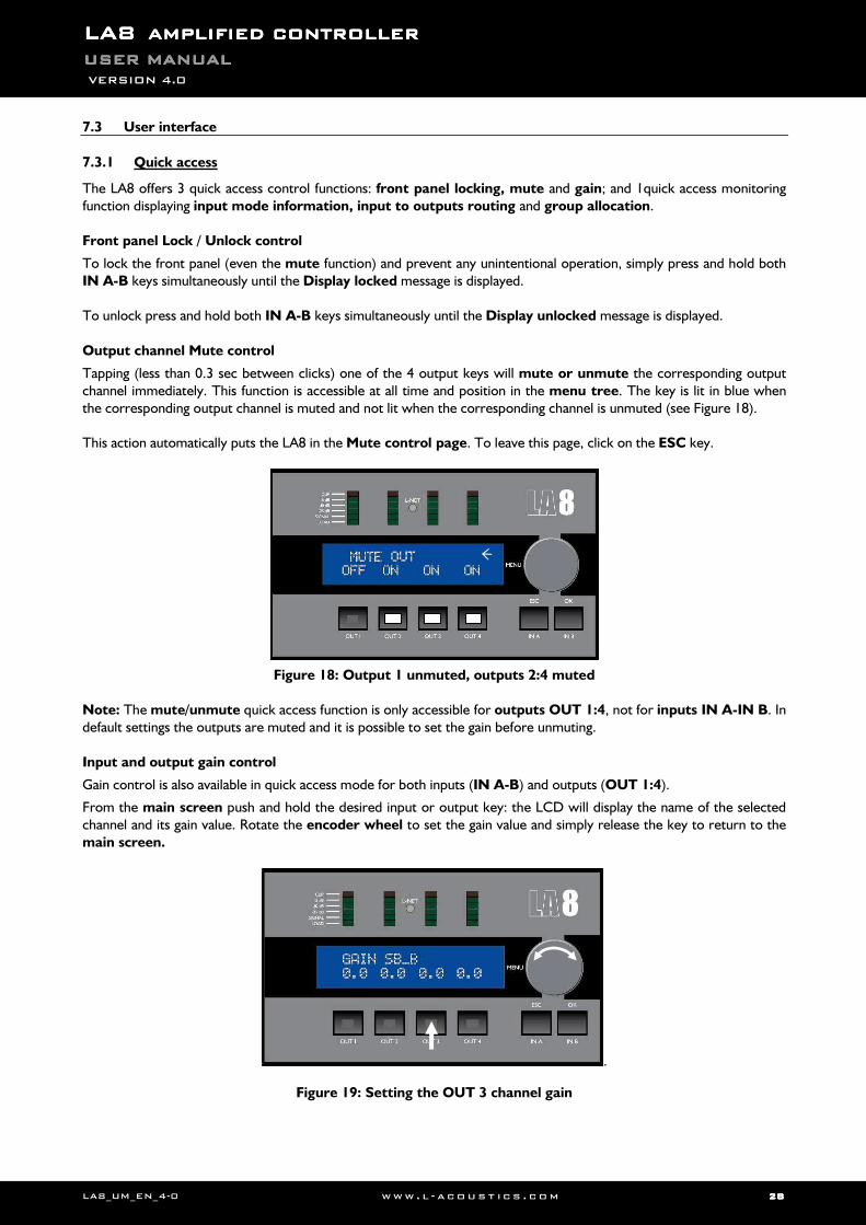
Tapping (less than 0.3 sec between clicks) one of the 4 output keys will mute or unmute the corresponding output channel immediately. This function is accessible at all time and position in the menu tree. The key is lit in blue when the corresponding output channel is muted and not lit when the corresponding channel is unmuted (see Figure 18). This action automatically puts the LA8 in the Mute control page. To leave this page, click on the ESC key.
Figure 18: Output 1 unmuted, outputs 2:4 muted
Note: The mute/unmute quick access function is only accessible for outputs OUT 1:4, not for inputs IN A-IN B. In default settings the outputs are muted and it is possible to set the gain before unmuting. Input and output gain control
Gain control is also available in quick access mode for both inputs (IN A-B) and outputs (OUT 1:4).
From the main screen push and hold the desired input or output key: the LCD will display the name of the selected channel and its gain value. Rotate the encoder wheel to set the gain value and simply release the key to return to the main screen.
.
Figure 19: Setting the OUT 3 channel gain
LA8_UM_EN_4-0 www . l - a co ust i c s . c o m 29292929
Notes: Quick access gain function is only available from the main screen.
Depending on the selected factory preset the output gain might be locked by L-ACOUSTICS®. In that case the LCD displays a cross (X) instead of a numeric value.
Gain values can be scaled at 0.1dB or 1dB resolution. To obtain 0.1dB resolution, simply rotate the encoder wheel. To obtain 1dB resolution, simultaneously push and rotate the encoder wheel.
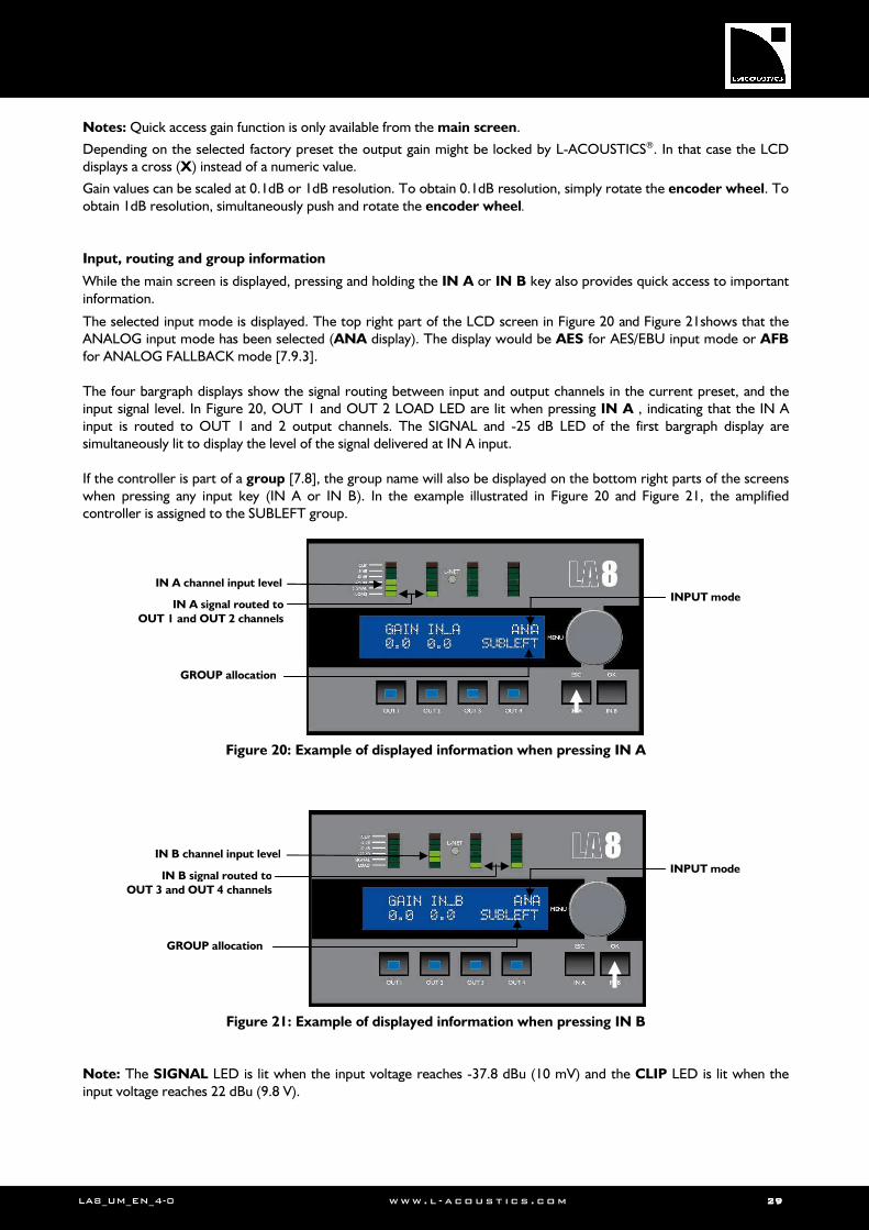
Input, routing and group information
While the main screen is displayed, pressing and holding the IN A or IN B key also provides quick access to important information.
The selected input mode is displayed. The top right part of the LCD screen in Figure 20 and Figure 21shows that the ANALOG input mode has been selected (ANA display). The display would be AES for AES/EBU input mode or AFB
for ANALOG FALLBACK mode [7.9.3]. The four bargraph displays show the signal routing between input and output channels in the current preset, and the input signal level. In Figure 20, OUT 1 and OUT 2 LOAD LED are lit when pressing IN A , indicating that the IN A input is routed to OUT 1 and 2 output channels. The SIGNAL and -25 dB LED of the first bargraph display are simultaneously lit to display the level of the signal delivered at IN A input. If the controller is part of a group [7.8], the group name will also be displayed on the bottom right parts of the screens when pressing any input key (IN A or IN B). In the example illustrated in Figure 20 and Figure 21, the amplified controller is assigned to the SUBLEFT group.
Figure 20: Example of displayed information when pressing IN A
Figure 21: Example of displayed information when pressing IN B Note: The SIGNAL LED is lit when the input voltage reaches -37.8 dBu (10 mV) and the CLIP LED is lit when the input voltage reaches 22 dBu (9.8 V).
IN A signal routed to
OUT 1 and OUT 2 channels
IN A channel input level
INPUT mode
GROUP allocation
GROUP allocation
IN B signal routed to
OUT 3 and OUT 4 channels
IN B channel input level
INPUT mode

LALALALA8888 AMPLIFIED CONTROLLERAMPLIFIED CONTROLLERAMPLIFIED CONTROLLERAMPLIFIED CONTROLLER USER MANUALUSER MANUALUSER MANUALUSER MANUAL VERSION 4.0
LA8_UM_EN_4-0 www . l - a co ust i c s . c o m 30303030
7.3.2 Main menu
The main menu gives access to 6 pages that are briefly described in the following table. Please refer to the appropriate section for detailed instructions. Note: All parameters in each amplified controller are also available through the L-NET network using LA NETWORK MANAGER Software (refer to the LA NETWORK MANAGER User manual [3.4]).
Table 5: Main menu description
Menu pages Functionalities Section
LOAD PRESET Load and initiate a preset (memories 1 to 99). [7.4]
STORE PRESET Save user preset and parameters (memories 1 to 10). [7.5]
DELETE PRESET Delete a preset (memories 1 to 10). [7.6]
PRESET PARAMETERS Control and set mute, gain, delay, and polarity (when available). [7.7]
CLEAR GRP PARAM Remove group parameters defined in LA NETWORK MANAGER Software (name, gain, delay, and contour EQ).
[7.8]
OPTIONS Select the LA8 IP address, input mode (ANALOG or AES/EBU), delay unit, and LCD screen contrast.
Provide real-time relative temperature and RMS output voltage for each amp channel.
Show MAC address as well as FIRMWARE, PRESET LIBRARY, and DISPLAY versions.
[7.9]
The following procedure and Figure 22 explain how to access one of these menus:
1. Press and release the encoder wheel.
2. Rotate the encoder wheel clockwise or counterclockwise until the desired menu is selected.
3. Press the OK key or the encoder wheel to enter menu or press the ESC key to return to the main screen.
Figure 22: Menu selection procedure
To simplify the navigation through the menu control screens, the LCD displays 2 types of arrow cursors: the position cursor (top left) and the selection cursor (top right).
Position cursors
Indicates the start of a menu and prompts the user to turn the encoder wheel clockwise to scroll down menu’s other functionalities.
Prompts the user to turn the encoder wheel clockwise or counterclockwise to scroll up and down menu’s other functionalities.
Indicates the end of a menu and prompts the user to turn the encoder wheel counterclockwise to scroll up menu’s other functionalities.
Selection cursors
Indicates another menu level or function, accessible by pressing the OK key or the encoder wheel. Press the ESC key to return to the last menu.
Indicates that no additional menu level or function is accessible. Turn the encoder wheel to access another menu or press the ESC key to return to the last menu.
LOAD PRESET STORE PRESET STORE PRESET DELETE PRESET DELETE PRESET PRESET PARAMETERS PRESET PARAMETERS CLEAR GRP PARAM CLEAR GRP PARAM OPTIONS 0.0 0.0 0.0 0.0 OPTIONS
LA8_UM_EN_4-0 www . l - a co ust i c s . c o m 31313131
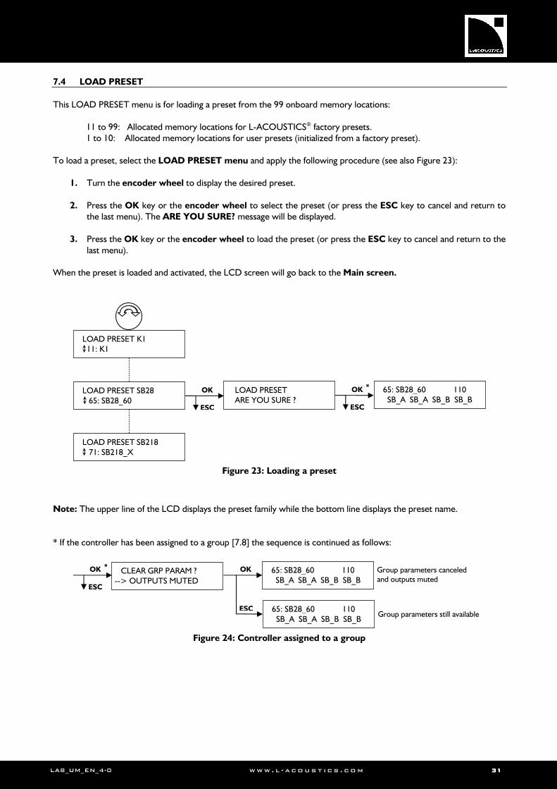
7.4 LOAD PRESET
This LOAD PRESET menu is for loading a preset from the 99 onboard memory locations:
11 to 99: Allocated memory locations for L-ACOUSTICS® factory presets. 1 to 10: Allocated memory locations for user presets (initialized from a factory preset).
To load a preset, select the LOAD PRESET menu and apply the following procedure (see also Figure 23):
1. Turn the encoder wheel to display the desired preset. 2. Press the OK key or the encoder wheel to select the preset (or press the ESC key to cancel and return to
the last menu). The ARE YOU SURE? message will be displayed.
3. Press the OK key or the encoder wheel to load the preset (or press the ESC key to cancel and return to the last menu).
When the preset is loaded and activated, the LCD screen will go back to the Main screen.
Figure 23: Loading a preset
Note: The upper line of the LCD displays the preset family while the bottom line displays the preset name. * If the controller has been assigned to a group [7.8] the sequence is continued as follows:
Figure 24: Controller assigned to a group
CLEAR GRP PARAM ? --> OUTPUTS MUTED
Group parameters still available
Group parameters canceled and outputs muted
* OK
ESC
OK
ESC
65: SB28_60 110 SB_A SB_A SB_B SB_B
65: SB28_60 110 SB_A SB_A SB_B SB_B
*
LOAD PRESET K1 11: K1
LOAD PRESET SB28 65: SB28_60
LOAD PRESET SB218 71: SB218_X
OK
ESC
LOAD PRESET ARE YOU SURE ?
OK
ESC
65: SB28_60 110 SB_A SB_A SB_B SB_B
LALALALA8888 AMPLIFIED CONTROLLERAMPLIFIED CONTROLLERAMPLIFIED CONTROLLERAMPLIFIED CONTROLLER USER MANUALUSER MANUALUSER MANUALUSER MANUAL VERSION 4.0
LA8_UM_EN_4-0 www . l - a co ust i c s . c o m 32323232
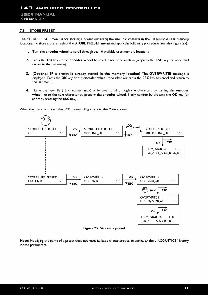
7.5 STORE PRESET
The STORE PRESET menu is for storing a preset (including the user parameters) in the 10 available user memory locations. To store a preset, select the STORE PRESET menu and apply the following procedure (see also Figure 25):
1. Turn the encoder wheel to scroll through the 10 available user memory locations. 2. Press the OK key or the encoder wheel to select a memory location (or press the ESC key to cancel and
return to the last menu).
3. (Optional: IF a preset is already stored in the memory location) The OVERWRITE? message is
displayed. Press the OK key or the encoder wheel to validate (or press the ESC key to cancel and return to the last menu).
4. Name the new file (13 characters max) as follows: scroll through the characters by turning the encoder
wheel, go to the next character by pressing the encoder wheel, finally confirm by pressing the OK key (or abort by pressing the ESC key).
When the preset is stored, the LCD screen will go back to the Main screen.
Figure 25: Storing a preset
Note: Modifying the name of a preset does not reset its basic characteristics, in particular the L-ACOUSTICS® factory locked parameters.
+push STORE USER PRESET 01:
STORE USER PRESET 10 : My K1
OK
ESC
STORE USER PRESET 01: SB28_60 ESC
STORE USER PRESET 01: My SB28_60
OK
ESC
OVERWRITE ? 10 : My K1
OVERWRITE ? 10 : SB28_60
OK
ESC
+push
OVERWRITE ? 10 : My SB28_60
01: My SB28_60 110 SB_A SB_A SB_B SB_B
OK ESC
ESC
10: My SB28_60 110 SB_A SB_A SB_B SB_B
OK ESC
LA8_UM_EN_4-0 www . l - a co ust i c s . c o m 33333333
7.6 DELETE PRESET
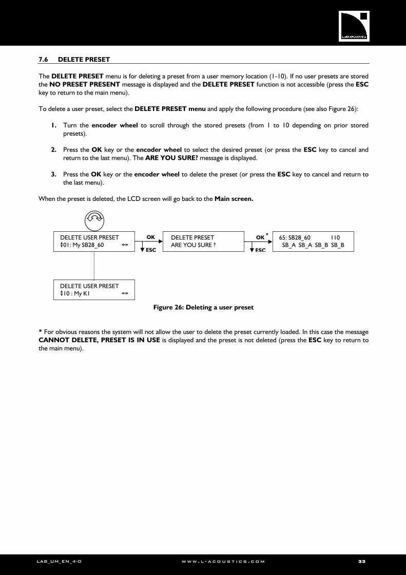
The DELETE PRESET menu is for deleting a preset from a user memory location (1-10). If no user presets are stored the NO PRESET PRESENT message is displayed and the DELETE PRESET function is not accessible (press the ESC key to return to the main menu). To delete a user preset, select the DELETE PRESET menu and apply the following procedure (see also Figure 26):
1. Turn the encoder wheel to scroll through the stored presets (from 1 to 10 depending on prior stored presets).
2. Press the OK key or the encoder wheel to select the desired preset (or press the ESC key to cancel and
return to the last menu). The ARE YOU SURE? message is displayed.
3. Press the OK key or the encoder wheel to delete the preset (or press the ESC key to cancel and return to the last menu).
When the preset is deleted, the LCD screen will go back to the Main screen.
Figure 26: Deleting a user preset * For obvious reasons the system will not allow the user to delete the preset currently loaded. In this case the message CANNOT DELETE, PRESET IS IN USE is displayed and the preset is not deleted (press the ESC key to return to the main menu).
* DELETE USER PRESET 01: My SB28_60
OK
ESC
DELETE USER PRESET 10 : My K1
DELETE PRESET ARE YOU SURE ?
OK
ESC
65: SB28_60 110 SB_A SB_A SB_B SB_B
LALALALA8888 AMPLIFIED CONTROLLERAMPLIFIED CONTROLLERAMPLIFIED CONTROLLERAMPLIFIED CONTROLLER USER MANUALUSER MANUALUSER MANUALUSER MANUAL VERSION 4.0
LA8_UM_EN_4-0 www . l - a co ust i c s . c o m 34343434
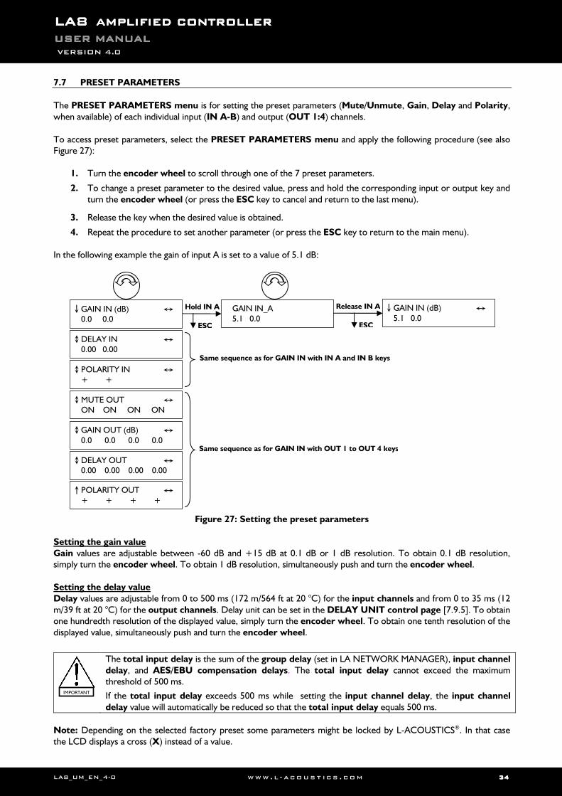
7.7 PRESET PARAMETERS
The PRESET PARAMETERS menu is for setting the preset parameters (Mute/Unmute, Gain, Delay and Polarity, when available) of each individual input (IN A-B) and output (OUT 1:4) channels. To access preset parameters, select the PRESET PARAMETERS menu and apply the following procedure (see also Figure 27):
1. Turn the encoder wheel to scroll through one of the 7 preset parameters.
2. To change a preset parameter to the desired value, press and hold the corresponding input or output key and turn the encoder wheel (or press the ESC key to cancel and return to the last menu).
3. Release the key when the desired value is obtained.
4. Repeat the procedure to set another parameter (or press the ESC key to return to the main menu). In the following example the gain of input A is set to a value of 5.1 dB:
Figure 27: Setting the preset parameters
Setting the gain value Gain values are adjustable between -60 dB and +15 dB at 0.1 dB or 1 dB resolution. To obtain 0.1 dB resolution, simply turn the encoder wheel. To obtain 1 dB resolution, simultaneously push and turn the encoder wheel. Setting the delay value Delay values are adjustable from 0 to 500 ms (172 m/564 ft at 20 °C) for the input channels and from 0 to 35 ms (12 m/39 ft at 20 °C) for the output channels. Delay unit can be set in the DELAY UNIT control page [7.9.5]. To obtain one hundredth resolution of the displayed value, simply turn the encoder wheel. To obtain one tenth resolution of the displayed value, simultaneously push and turn the encoder wheel.
The total input delay is the sum of the group delay (set in LA NETWORK MANAGER), input channel delay, and AES/EBU compensation delays. The total input delay cannot exceed the maximum threshold of 500 ms.
If the total input delay exceeds 500 ms while setting the input channel delay, the input channel delay value will automatically be reduced so that the total input delay equals 500 ms.
Note: Depending on the selected factory preset some parameters might be locked by L-ACOUSTICS®. In that case the LCD displays a cross (X) instead of a value.
Same sequence as for GAIN IN with IN A and IN B keys
Same sequence as for GAIN IN with OUT 1 to OUT 4 keys
GAIN IN (dB) 0.0 0.0
Hold IN A
ESC
GAIN IN_A 5.1 0.0
Release IN A
ESC
GAIN IN (dB) 5.1 0.0
DELAY IN 0.00 0.00 POLARITY IN + + MUTE OUT ON ON ON ON GAIN OUT (dB) 0.0 0.0 0.0 0.0
DELAY OUT 0.00 0.00 0.00 0.00
POLARITY OUT + + + +
IMPORTANT
LA8_UM_EN_4-0 www . l - a co ust i c s . c o m 35353535
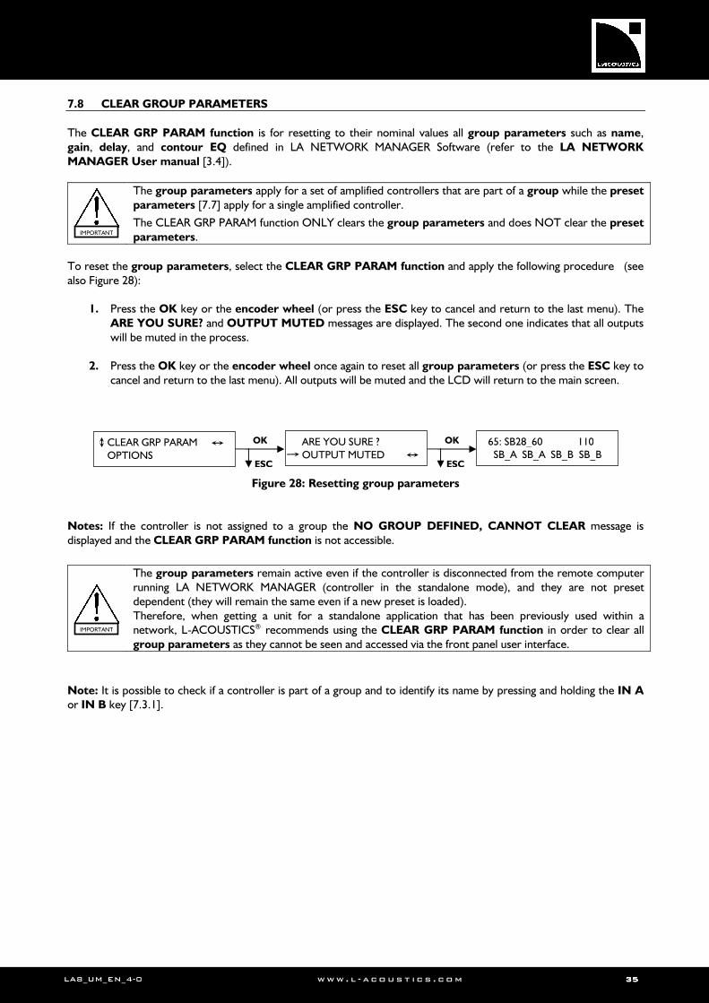
7.8 CLEAR GROUP PARAMETERS
The CLEAR GRP PARAM function is for resetting to their nominal values all group parameters such as name, gain, delay, and contour EQ defined in LA NETWORK MANAGER Software (refer to the LA NETWORK
MANAGER User manual [3.4]).
The group parameters apply for a set of amplified controllers that are part of a group while the preset parameters [7.7] apply for a single amplified controller.
The CLEAR GRP PARAM function ONLY clears the group parameters and does NOT clear the preset parameters.
To reset the group parameters, select the CLEAR GRP PARAM function and apply the following procedure (see also Figure 28):
1. Press the OK key or the encoder wheel (or press the ESC key to cancel and return to the last menu). The ARE YOU SURE? and OUTPUT MUTED messages are displayed. The second one indicates that all outputs will be muted in the process.
2. Press the OK key or the encoder wheel once again to reset all group parameters (or press the ESC key to
cancel and return to the last menu). All outputs will be muted and the LCD will return to the main screen.
Figure 28: Resetting group parameters
Notes: If the controller is not assigned to a group the NO GROUP DEFINED, CANNOT CLEAR message is displayed and the CLEAR GRP PARAM function is not accessible.
The group parameters remain active even if the controller is disconnected from the remote computer running LA NETWORK MANAGER (controller in the standalone mode), and they are not preset dependent (they will remain the same even if a new preset is loaded). Therefore, when getting a unit for a standalone application that has been previously used within a network, L-ACOUSTICS® recommends using the CLEAR GRP PARAM function in order to clear all group parameters as they cannot be seen and accessed via the front panel user interface.
Note: It is possible to check if a controller is part of a group and to identify its name by pressing and holding the IN A or IN B key [7.3.1].
65: SB28_60 110 SB_A SB_A SB_B SB_B
OK
ESC
CLEAR GRP PARAM OPTIONS
ARE YOU SURE ? OUTPUT MUTED
OK
ESC
IMPORTANT
IMPORTANT
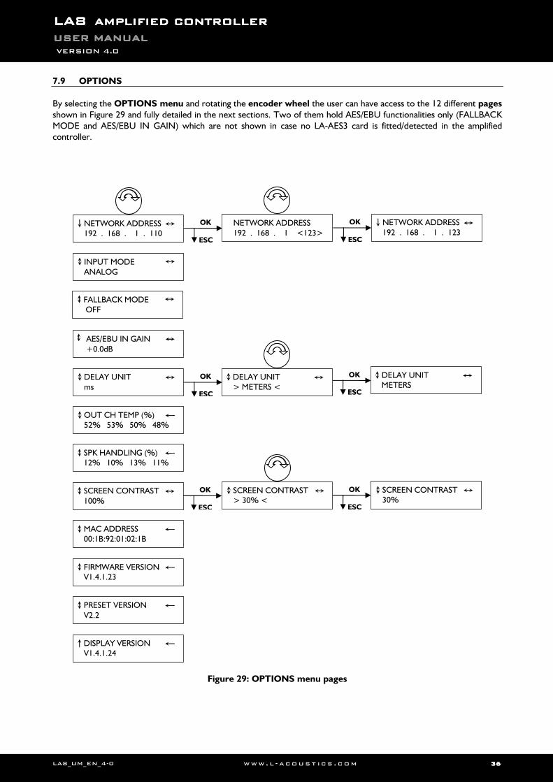
LALALALA8888 AMPLIFIED CONTROLLERAMPLIFIED CONTROLLERAMPLIFIED CONTROLLERAMPLIFIED CONTROLLER USER MANUALUSER MANUALUSER MANUALUSER MANUAL VERSION 4.0
LA8_UM_EN_4-0 www . l - a co ust i c s . c o m 36363636
7.9 OPTIONS
By selecting the OPTIONS menu and rotating the encoder wheel the user can have access to the 12 different pages shown in Figure 29 and fully detailed in the next sections. Two of them hold AES/EBU functionalities only (FALLBACK MODE and AES/EBU IN GAIN) which are not shown in case no LA-AES3 card is fitted/detected in the amplified controller.
Figure 29: OPTIONS menu pages
NETWORK ADDRESS 192 . 168 . 1 . 110
INPUT MODE ANALOG
DELAY UNIT ms
OUT CH TEMP (%) 52% 53% 50% 48%
SPK HANDLING (%) 12% 10% 13% 11%
SCREEN CONTRAST 100%
MAC ADDRESS 00:1B:92:01:02:1B
FIRMWARE VERSION V1.4.1.23
PRESET VERSION V2.2
DISPLAY VERSION V1.4.1.24
OK
ESC
NETWORK ADDRESS 192 . 168 . 1 <123>
OK
ESC
NETWORK ADDRESS 192 . 168 . 1 . 123
OK
ESC
DELAY UNIT > METERS <
OK
ESC
DELAY UNIT METERS
OK
ESC
SCREEN CONTRAST > 30% <
OK
ESC
SCREEN CONTRAST 30%
AES/EBU IN GAIN
+0.0dB
FALLBACK MODE OFF
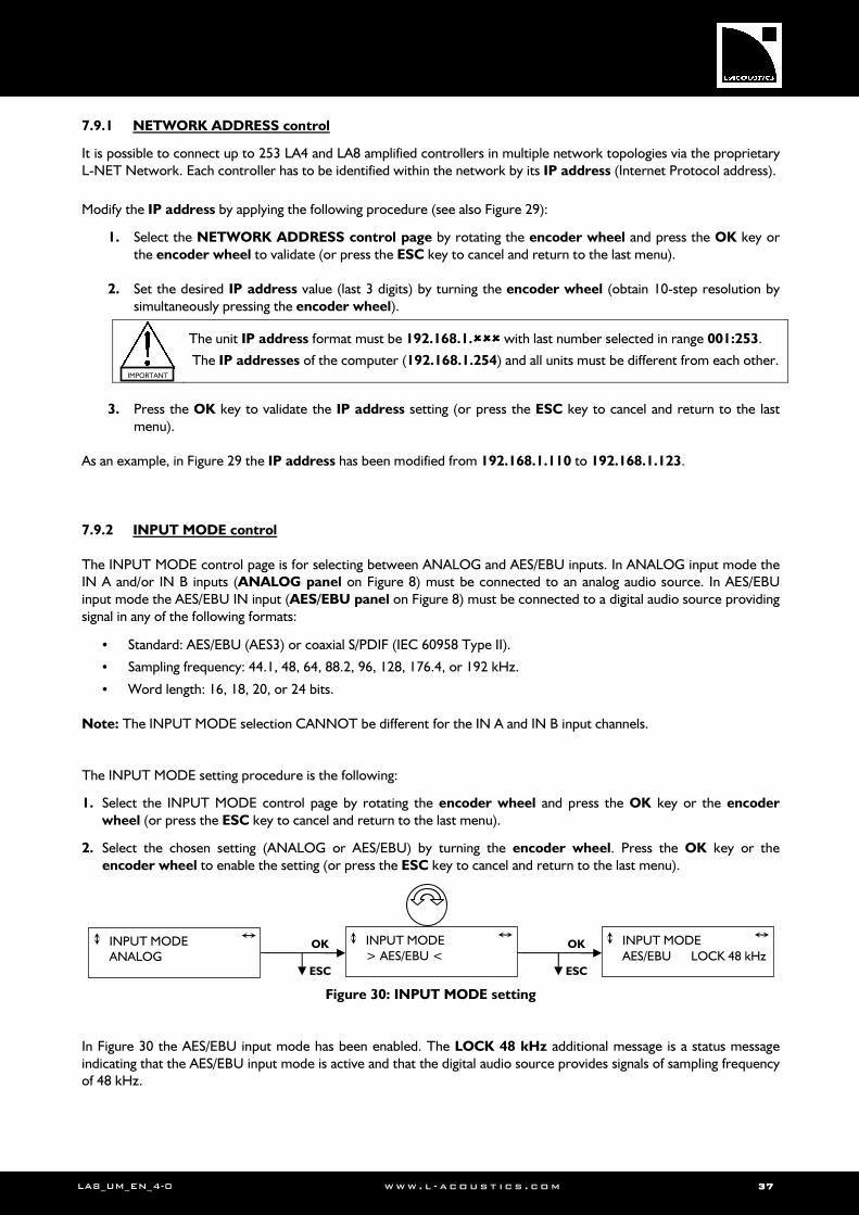
LA8_UM_EN_4-0 www . l - a co ust i c s . c o m 37373737
7.9.1 NETWORK ADDRESS control
It is possible to connect up to 253 LA4 and LA8 amplified controllers in multiple network topologies via the proprietary L-NET Network. Each controller has to be identified within the network by its IP address (Internet Protocol address).
Modify the IP address by applying the following procedure (see also Figure 29):
1. Select the NETWORK ADDRESS control page by rotating the encoder wheel and press the OK key or the encoder wheel to validate (or press the ESC key to cancel and return to the last menu).
2. Set the desired IP address value (last 3 digits) by turning the encoder wheel (obtain 10-step resolution by
simultaneously pressing the encoder wheel).
The unit IP address format must be 192.168.1. with last number selected in range 001:253.
The IP addresses of the computer (192.168.1.254) and all units must be different from each other.
3. Press the OK key to validate the IP address setting (or press the ESC key to cancel and return to the last
menu). As an example, in Figure 29 the IP address has been modified from 192.168.1.110 to 192.168.1.123.
7.9.2 INPUT MODE control
The INPUT MODE control page is for selecting between ANALOG and AES/EBU inputs. In ANALOG input mode the IN A and/or IN B inputs (ANALOG panel on Figure 8) must be connected to an analog audio source. In AES/EBU input mode the AES/EBU IN input (AES/EBU panel on Figure 8) must be connected to a digital audio source providing signal in any of the following formats:
• Standard: AES/EBU (AES3) or coaxial S/PDIF (IEC 60958 Type II).
• Sampling frequency: 44.1, 48, 64, 88.2, 96, 128, 176.4, or 192 kHz.
• Word length: 16, 18, 20, or 24 bits. Note: The INPUT MODE selection CANNOT be different for the IN A and IN B input channels. The INPUT MODE setting procedure is the following:
1. Select the INPUT MODE control page by rotating the encoder wheel and press the OK key or the encoder wheel (or press the ESC key to cancel and return to the last menu).
2. Select the chosen setting (ANALOG or AES/EBU) by turning the encoder wheel. Press the OK key or the encoder wheel to enable the setting (or press the ESC key to cancel and return to the last menu).
Figure 30: INPUT MODE setting
In Figure 30 the AES/EBU input mode has been enabled. The LOCK 48 kHz additional message is a status message indicating that the AES/EBU input mode is active and that the digital audio source provides signals of sampling frequency of 48 kHz.
INPUT MODE ANALOG
INPUT MODE > AES/EBU <
INPUT MODE AES/EBU LOCK 48 kHz
OK
ESC
OK
ESC
IMPORTANT
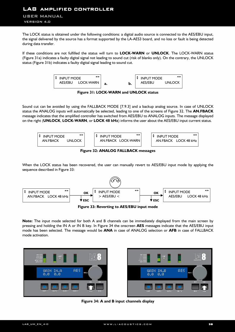
LALALALA8888 AMPLIFIED CONTROLLERAMPLIFIED CONTROLLERAMPLIFIED CONTROLLERAMPLIFIED CONTROLLER USER MANUALUSER MANUALUSER MANUALUSER MANUAL VERSION 4.0
LA8_UM_EN_4-0 www . l - a co ust i c s . c o m 38383838
The LOCK status is obtained under the following conditions: a digital audio source is connected to the AES/EBU input, the signal delivered by the source has a format supported by the LA-AES3 board, and no loss or fault is being detected during data transfer. If these conditions are not fulfilled the status will turn to LOCK-WARN or UNLOCK. The LOCK-WARN status (Figure 31a) indicates a faulty digital signal not leading to sound cut (risk of blanks only). On the contrary, the UNLOCK status (Figure 31b) indicates a faulty digital signal leading to sound cut.
Figure 31: LOCK-WARN and UNLOCK status
Sound cut can be avoided by using the FALLBACK MODE [7.9.3] and a backup analog source. In case of UNLOCK status the ANALOG inputs will automatically be selected, leading to one of the screens of Figure 32. The AN.FBACK message indicates that the amplified controller has switched from AES/EBU to ANALOG inputs. The message displayed on the right (UNLOCK, LOCK-WARN, or LOCK 48 kHz) informs the user about the AES/EBU input current status.
Figure 32: ANALOG FALLBACK messages
When the LOCK status has been recovered, the user can manually revert to AES/EBU input mode by applying the sequence described in Figure 33:
Figure 33: Reverting to AES/EBU input mode
Note: The input mode selected for both A and B channels can be immediately displayed from the main screen by pressing and holding the IN A or IN B key. In Figure 34 the onscreen AES messages indicate that the AES/EBU input mode has been selected. The message would be ANA in case of ANALOG selection or AFB in case of FALLBACK mode activation.
Figure 34: A and B input channels display
INPUT MODE AES/EBU LOCK-WARN
INPUT MODE AES/EBU UNLOCK a. b.
INPUT MODE AN.FBACK UNLOCK
INPUT MODE AN.FBACK LOCK-WARN
INPUT MODE AN.FBACK LOCK 48 kHz
INPUT MODE > AES/EBU <
INPUT MODE AES/EBU LOCK 48 kHz
OK
ESC
OK
ESC
INPUT MODE AN.FBACK LOCK 48 kHz
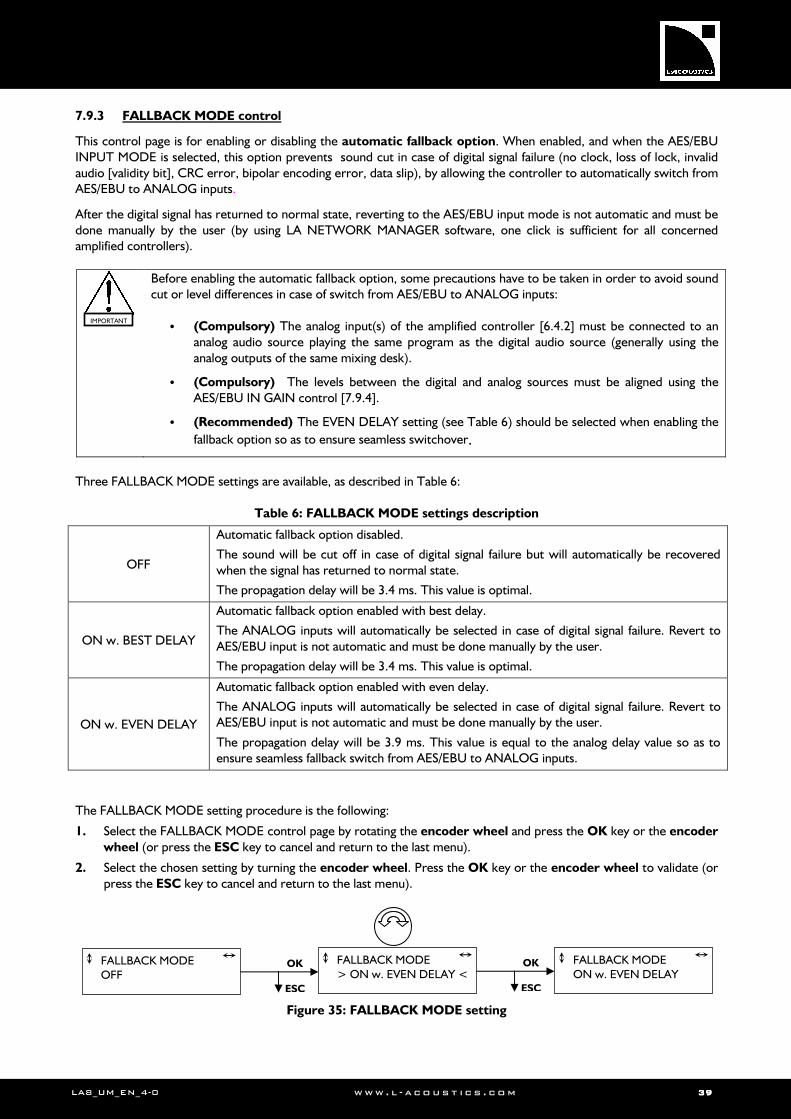
LA8_UM_EN_4-0 www . l - a co ust i c s . c o m 39393939
7.9.3 FALLBACK MODE control
This control page is for enabling or disabling the automatic fallback option. When enabled, and when the AES/EBU INPUT MODE is selected, this option prevents sound cut in case of digital signal failure (no clock, loss of lock, invalid audio [validity bit], CRC error, bipolar encoding error, data slip), by allowing the controller to automatically switch from AES/EBU to ANALOG inputs.
After the digital signal has returned to normal state, reverting to the AES/EBU input mode is not automatic and must be done manually by the user (by using LA NETWORK MANAGER software, one click is sufficient for all concerned amplified controllers).
Before enabling the automatic fallback option, some precautions have to be taken in order to avoid sound cut or level differences in case of switch from AES/EBU to ANALOG inputs:
• (Compulsory) The analog input(s) of the amplified controller [6.4.2] must be connected to an analog audio source playing the same program as the digital audio source (generally using the analog outputs of the same mixing desk).
• (Compulsory) The levels between the digital and analog sources must be aligned using the AES/EBU IN GAIN control [7.9.4].
• (Recommended) The EVEN DELAY setting (see Table 6) should be selected when enabling the
fallback option so as to ensure seamless switchover.
Three FALLBACK MODE settings are available, as described in Table 6:
Table 6: FALLBACK MODE settings description
OFF
Automatic fallback option disabled.
The sound will be cut off in case of digital signal failure but will automatically be recovered when the signal has returned to normal state.
The propagation delay will be 3.4 ms. This value is optimal.
ON w. BEST DELAY
Automatic fallback option enabled with best delay.
The ANALOG inputs will automatically be selected in case of digital signal failure. Revert to AES/EBU input is not automatic and must be done manually by the user.
The propagation delay will be 3.4 ms. This value is optimal.
ON w. EVEN DELAY
Automatic fallback option enabled with even delay.
The ANALOG inputs will automatically be selected in case of digital signal failure. Revert to AES/EBU input is not automatic and must be done manually by the user.
The propagation delay will be 3.9 ms. This value is equal to the analog delay value so as to ensure seamless fallback switch from AES/EBU to ANALOG inputs.
The FALLBACK MODE setting procedure is the following:
1. Select the FALLBACK MODE control page by rotating the encoder wheel and press the OK key or the encoder wheel (or press the ESC key to cancel and return to the last menu).
2. Select the chosen setting by turning the encoder wheel. Press the OK key or the encoder wheel to validate (or press the ESC key to cancel and return to the last menu).
Figure 35: FALLBACK MODE setting
FALLBACK MODE OFF
FALLBACK MODE > ON w. EVEN DELAY <
FALLBACK MODE ON w. EVEN DELAY
OK
ESC
OK
ESC
IMPORTANT
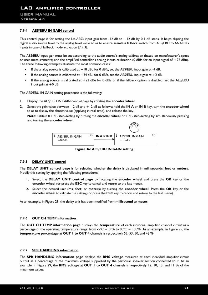
LALALALA8888 AMPLIFIED CONTROLLERAMPLIFIED CONTROLLERAMPLIFIED CONTROLLERAMPLIFIED CONTROLLER USER MANUALUSER MANUALUSER MANUALUSER MANUAL VERSION 4.0
LA8_UM_EN_4-0 www . l - a co ust i c s . c o m 40404040
7.9.4 AES/EBU IN GAIN control
This control page is for setting the LA-AES3 input gain from -12 dB to +12 dB by 0.1 dB steps. It helps aligning the digital audio source level to the analog level value so as to ensure seamless fallback switch from AES/EBU to ANALOG inputs in case of fallback mode activation [7.9.3]. The AES/EBU input gain must be set according to the audio source’s analog calibration (based on manufacturer’s specs or user measurements) and the amplified controller’s analog inputs calibration (0 dBfs for an input signal of +22 dBu). The three following examples illustrate the most common cases:
• If the analog source is calibrated at +18 dBu for 0 dBfs, set the AES/EBU input gain at -4 dB.
• If the analog source is calibrated at +24 dBu for 0 dBfs, set the AES/EBU input gain at +2 dB.
• If the analog source is calibrated at +22 dBu for 0 dBfs or if the fallback option is disabled, set the AES/EBU input gain at +0 dB.
The AES/EBU IN GAIN setting procedure is the following: 1. Display the AES/EBU IN GAIN control page by rotating the encoder wheel.
2. Select the gain value between -12 dB and +12 dB as follows: hold the IN A or IN B key, turn the encoder wheel so as to display the chosen value (applying in real-time), and release the key.
Note: Obtain 0.1 dB step-setting by turning the encoder wheel or 1 dB step-setting by simultaneously pressing and turning the encoder wheel.
Figure 36: AES/EBU IN GAIN setting
7.9.5 DELAY UNIT control
The DELAY UNIT control page is for selecting whether the delay is displayed in milliseconds, feet or meters. Modify this setting by applying the following procedure:
1. Select the DELAY UNIT control page by rotating the encoder wheel and press the OK key or the encoder wheel (or press the ESC key to cancel and return to the last menu).
2. Select the desired unit (ms, feet, or meters) by turning the encoder wheel. Press the OK key or the encoder wheel to validate the setting (or press the ESC key to cancel and return to the last menu).
As an example, in Figure 29, the delay unit has been modified from millisecond to meter. 7.9.6 OUT CH TEMP information
The OUT CH TEMP information page displays the temperature of each individual amplifier channel circuit as a percentage of the operating temperature range: from -5°C = 0 % to 85°C = 100%. As an example, in Figure 29, the temperature percentage at OUT 1 to OUT 4 channels is respectively 52, 53, 50, and 48 %. 7.9.7 SPK HANDLING information
The SPK HANDLING information page displays the RMS voltage measured at each individual amplifier circuit output as a percentage of the maximum voltage supported by the particular speaker section connected to it. As an example, in Figure 29, the RMS voltage at OUT 1 to OUT 4 channels is respectively 12, 10, 13, and 11 % of the maximum values.
IN A or IN B AES/EBU IN GAIN +0.0dB
AES/EBU IN GAIN +1.5dB
LA8_UM_EN_4-0 www . l - a co ust i c s . c o m 41414141
7.9.8 SCREEN CONTRAST control
The SCREEN CONTRAST control page is for setting the LCD screen contrast. Modify this setting by applying the following procedure:
1. Select the SCREEN CONTRAST control page by rotating the encoder wheel and press the OK key or the encoder wheel (or press the ESC key to cancel and return to the last menu).
2. Select the desired value (between 0 and 100 %) by turning the encoder wheel. Press the OK key or the encoder wheel to validate the setting (or press the ESC key to cancel and return to the last menu).
As an example, in Figure 29, the contrast has been modified from 100 % to 30 %. 7.9.9 MAC ADDRESS information
The MAC ADDRESS information page displays the MAC (Media Access Control) address of the current controller. This address (unique to each controller) is the equivalent of a serial number and identifies the controller internationally. It is set by the manufacturer and cannot be modified.
As an example, Figure 29, shows MAC address 00 :1B :92 :01 :02 :1B. 7.9.10 FIRMWARE VERSION information
The FIRMWARE VERSION information page displays the version of LA8 FIRMWARE in use in the controller.
As an example, Figure 29 shows LA8 FIRMWARE version 1.4.1.23. Refer to [8.1] if update is needed.
ALWAYS ensure that all controllers used in a given network run the same FIRMWARE version.
7.9.11 PRESET VERSION information
The PRESET VERSION information page displays the version of the LA8 PRESET LIBRARY in use in the controller.
As an example, Figure 29 shows LA8 PRESET LIBRARY version 2.2. Refer to [8.1] if update is needed. 7.9.12 DISPLAY VERSION information
The DISPLAY VERSION information page displays the version of the LA8 DISPLAY program in use in the controller. As an example, Figure 29 shows LA8 DISPLAY version 1.4.1.24.
IMPORTANT
LALALALA8888 AMPLIFIED CONTROLLERAMPLIFIED CONTROLLERAMPLIFIED CONTROLLERAMPLIFIED CONTROLLER USER MANUALUSER MANUALUSER MANUALUSER MANUAL VERSION 4.0
LA8_UM_EN_4-0 www . l - a co ust i c s . c o m 42424242
8888 CARE AND MAINTENANCECARE AND MAINTENANCECARE AND MAINTENANCECARE AND MAINTENANCE
8.1 Maintenance information
L-ACOUSTICS® amplified controllers are quality units and should provide years of trouble-free services when operated under normal conditions. However, in order to ensure product performance and safety, it is essential to frequently inspect the amplified controller. These checks and maintenance operations need to be done on a regular basis depending on the conditions of the system use:
• Check the versions of FIRMWARE [7.9.10] and PRESET LIBRARY [7.9.11] installed in the controller. Check the L-ACOUSTICS® web site for latest versions. If needed, proceed to an update. Refer to the LA4-8
FIRMWARE UPDATE Technical bulletin and LA4-8 PRESET LIBRARIES UPDATE Technical bulletin (included in the LA8 FIRMWARE Pack and LA8 PRESET LIBRARY Pack [3.4]) for full description of the processes.
• Clean or replace the FOAM FILTER [8.2.2].
If the FOAM FILTER becomes clogged the amplified controller will not cool as efficiently as it should, thus reducing the output power capability and overheating the electronic components.
• Clean the inside of the controller, especially after long operation periods in very dusty or cracked-oil smoke machine environments.
Cleaning and servicing the inside of an amplified controller must be done by qualified personnel ONLY.
• Replace the front FRAME if it is damaged [8.2.2].
Any controller showing any sign of defect must immediately be put aside and withdrawn from use to be inspected by qualified service personnel.
During the decommissioning process of the amplified controller all legally prescribed rules and procedures must be adhered to.
VOLTAGE
VOLTAGE
IMPORTANT
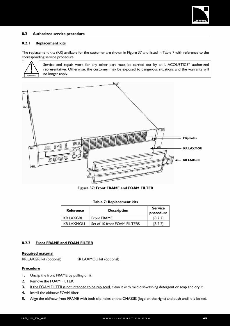
LA8_UM_EN_4-0 www . l - a co ust i c s . c o m 43434343
8.2 Authorized service procedure
8.2.1 Replacement kits
The replacement kits (KR) available for the customer are shown in Figure 37 and listed in Table 7 with reference to the corresponding service procedure. *
Service and repair work for any other part must be carried out by an L-ACOUSTICS® authorized representative. Otherwise, the customer may be exposed to dangerous situations and the warranty will no longer apply.
Figure 37: Front FRAME and FOAM FILTER
Table 7: Replacement kits
Reference Description Service
procedure
KR LAXGRI Front FRAME [8.2.2]
KR LAXMOU Set of 10 front FOAM FILTERS [8.2.2]
8.2.2 Front FRAME and FOAM FILTER
Required material
KR LAXGRI kit (optional) KR LAXMOU kit (optional) Procedure
1. Unclip the front FRAME by pulling on it.
2. Remove the FOAM FILTER.
3. If the FOAM FILTER is not intended to be replaced, clean it with mild dishwashing detergent or soap and dry it.
4. Install the old/new FOAM filter.
5. Align the old/new front FRAME with both clip holes on the CHASSIS (logo on the right) and push until it is locked.
WARNING
KR LAXGRI
KR LAXMOU
Clip holes
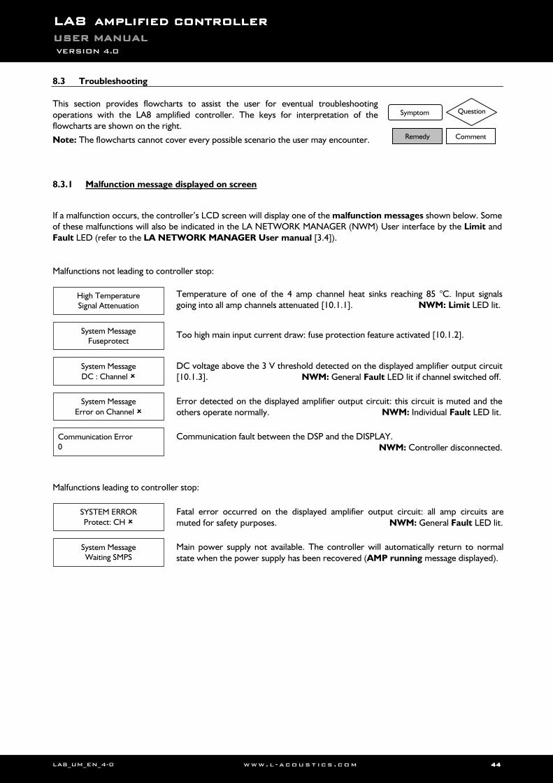
LALALALA8888 AMPLIFIED CONTROLLERAMPLIFIED CONTROLLERAMPLIFIED CONTROLLERAMPLIFIED CONTROLLER USER MANUALUSER MANUALUSER MANUALUSER MANUAL VERSION 4.0
LA8_UM_EN_4-0 www . l - a co ust i c s . c o m 44444444
8.3 Troubleshooting
This section provides flowcharts to assist the user for eventual troubleshooting operations with the LA8 amplified controller. The keys for interpretation of the flowcharts are shown on the right.
Note: The flowcharts cannot cover every possible scenario the user may encounter. 8.3.1 Malfunction message displayed on screen
If a malfunction occurs, the controller’s LCD screen will display one of the malfunction messages shown below. Some of these malfunctions will also be indicated in the LA NETWORK MANAGER (NWM) User interface by the Limit and Fault LED (refer to the LA NETWORK MANAGER User manual [3.4]). Malfunctions not leading to controller stop:
Temperature of one of the 4 amp channel heat sinks reaching 85 °C. Input signals going into all amp channels attenuated [10.1.1]. NWM: Limit LED lit.
Too high main input current draw: fuse protection feature activated [10.1.2].
DC voltage above the 3 V threshold detected on the displayed amplifier output circuit [10.1.3]. NWM: General Fault LED lit if channel switched off.
Error detected on the displayed amplifier output circuit: this circuit is muted and the others operate normally. NWM: Individual Fault LED lit.
Communication fault between the DSP and the DISPLAY. NWM: Controller disconnected.
Malfunctions leading to controller stop:
Fatal error occurred on the displayed amplifier output circuit: all amp circuits are muted for safety purposes. NWM: General Fault LED lit.
Main power supply not available. The controller will automatically return to normal state when the power supply has been recovered (AMP running message displayed).
High Temperature Signal Attenuation
System Message Fuseprotect
System Message
DC : Channel
System Message
Error on Channel
SYSTEM ERROR Protect: CH
System Message Waiting SMPS
Communication Error 0
Symptom
Remedy
Question
Comment
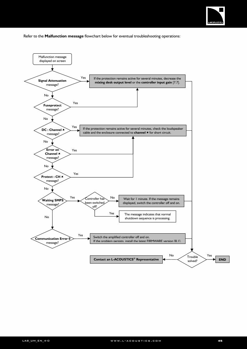
LA8_UM_EN_4-0 www . l - a co ust i c s . c o m 45454545
Refer to the Malfunction message flowchart below for eventual troubleshooting operations:
No
Switch the amplified controller off and on. If the problem persists, install the latest FIRMWARE version [8.1].
Waiting SMPS message?
Malfunction message displayed on screen
Yes Wait for 1 minute. If the message remains displayed, switch the controller off and on.
Protect : CH message?
Yes
Error on Channel message?
Yes
DC : Channel message?
Yes If the protection remains active for several minutes, check the loudspeaker cable and the enclosure connected to channel for short circuit.
Fuseprotect message?
Yes
Signal Attenuation
message?
Yes If the protection remains active for several minutes, decrease the mixing desk output level or the controller input gain [7.7].
No
No
No
No
No
Controller has been switched
off?
Yes
No
The message indicates that normal shutdown sequence is processing.
Yes
Yes Trouble solved? END
No
Contact an L-ACOUSTICS® Representative
Communication Error 0 message?
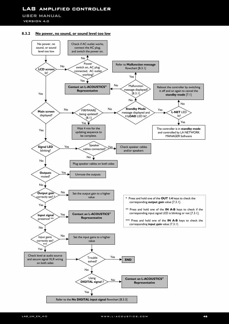
LALALALA8888 AMPLIFIED CONTROLLERAMPLIFIED CONTROLLERAMPLIFIED CONTROLLERAMPLIFIED CONTROLLER USER MANUALUSER MANUALUSER MANUALUSER MANUAL VERSION 4.0
LA8_UM_EN_4-0 www . l - a co ust i c s . c o m 46464646
8.3.2 No power, no sound, or sound level too low
LCD screen lit?
Main screen displayed?
Signal LED blinking?
Outputs muted?
Input signal presence? **
Output gain correctly set? *
Speaker cables connected?
The controller is in standby mode and controlled by LA NETWORK
MANAGER Software
Reboot the controller by switching it off and on again to cancel the
standby mode [7.1]
Check if AC outlet works, connect the AC plug,
and switch the power on.
Check speaker cables and/or speakers
Plug speaker cables on both sides
Unmute the outputs
Set the output gain to a higher value
Yes
Yes
No
Yes
Yes Yes
No
No No
No No
No
No
Yes
* Press and hold one of the OUT 1:4 keys to check the corresponding output gain value [7.3.1].
** Press and hold one of the IN A-B keys to check if the
corresponding input signal LED is blinking or not [7.3.1]. *** Press and hold one of the IN A-B keys to check the
corresponding input gain value [7.3.1].
Malfunction message displayed?
[8.3.1] Yes
Power switch on, AC plug
connected, AC outlet working?
No
Yes
FIRMWARE being updated?
[8.1]
Wait 4 min for the updating sequence to
be complete.
Yes
No power, no sound, or sound
level too low
Refer to Malfunction message flowchart [8.3.1]
Standby Mode message displayed and
4 LOAD LED lit?
Yes
Yes
No
No
L-NET LED lit?
Yes
No
Contact an L-ACOUSTICS®
Representative
Contact an L-ACOUSTICS®
Representative
Check level at audio source and secure signal XLR wiring
on both sides
Using DIGITAL signal ?
No
Refer to the No DIGITAL input signal flowchart [8.3.3]
Set the input gains to a higher value
Input gains correctly set?
***
Yes
No
Yes
Trouble solved?
END
No Contact an L-ACOUSTICS®
Representative
Yes
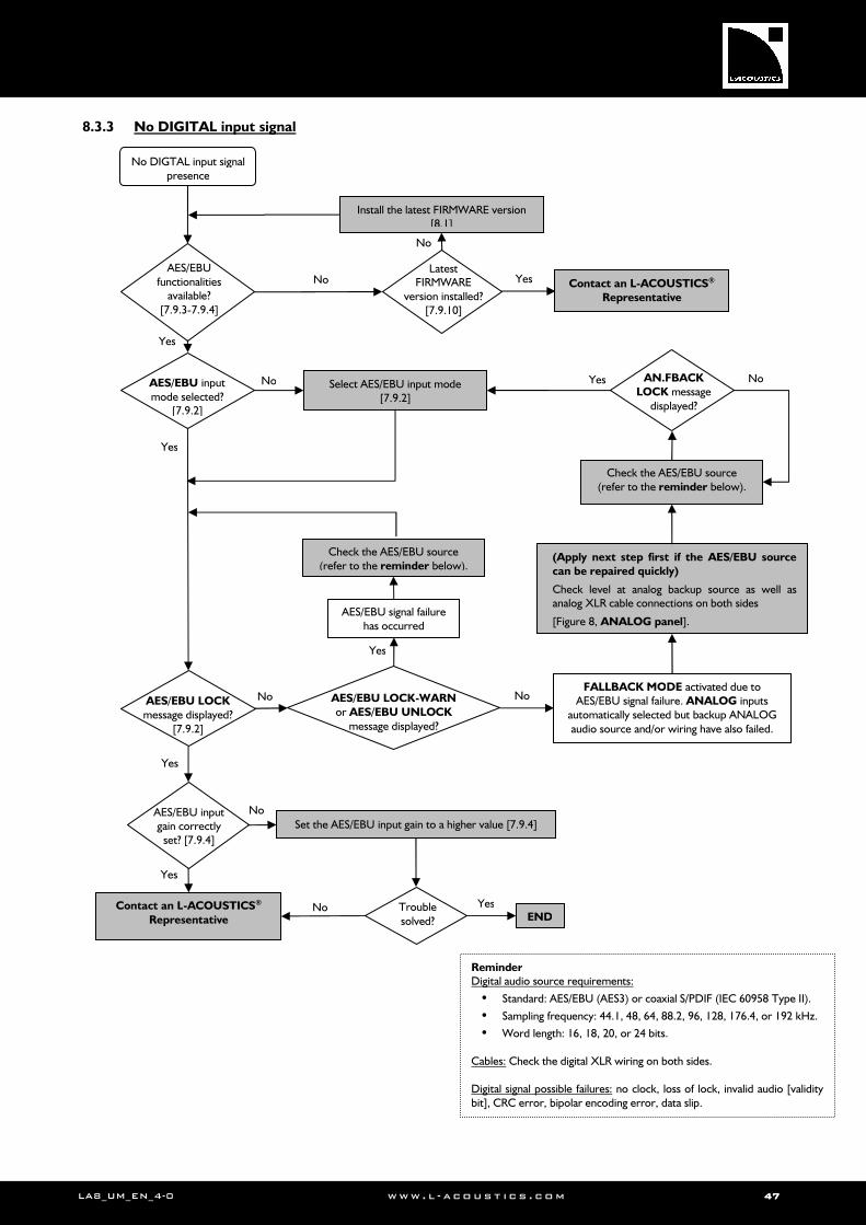
LA8_UM_EN_4-0 www . l - a co ust i c s . c o m 47474747
8.3.3 No DIGITAL input signal
AES/EBU functionalities
available? [7.9.3-7.9.4]
AES/EBU LOCK message displayed?
[7.9.2]
Install the latest FIRMWARE version [8.1]
Latest FIRMWARE
version installed? [7.9.10]
No DIGTAL input signal presence
AES/EBU input gain correctly
set? [7.9.4]
Set the AES/EBU input gain to a higher value [7.9.4]
No
Yes
No
(Apply next step first if the AES/EBU source can be repaired quickly)
Check level at analog backup source as well as analog XLR cable connections on both sides
[Figure 8, ANALOG panel].
Yes
AES/EBU input mode selected?
[7.9.2]
Yes
No Select AES/EBU input mode [7.9.2]
FALLBACK MODE activated due to AES/EBU signal failure. ANALOG inputs
automatically selected but backup ANALOG audio source and/or wiring have also failed.
AES/EBU signal failure has occurred
Reminder Digital audio source requirements:
• Standard: AES/EBU (AES3) or coaxial S/PDIF (IEC 60958 Type II).
• Sampling frequency: 44.1, 48, 64, 88.2, 96, 128, 176.4, or 192 kHz.
• Word length: 16, 18, 20, or 24 bits. Cables: Check the digital XLR wiring on both sides. Digital signal possible failures: no clock, loss of lock, invalid audio [validity bit], CRC error, bipolar encoding error, data slip.
AES/EBU LOCK-WARN or AES/EBU UNLOCK
message displayed?
No
Yes
AN.FBACK LOCK message
displayed?
Yes No
Check the AES/EBU source (refer to the reminder below).
Check the AES/EBU source (refer to the reminder below).
Yes
No
No
Contact an L-ACOUSTICS® Representative
Yes
Yes Trouble solved? END
Contact an L-ACOUSTICS®
Representative No
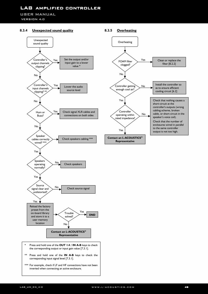
LALALALA8888 AMPLIFIED CONTROLLERAMPLIFIED CONTROLLERAMPLIFIED CONTROLLERAMPLIFIED CONTROLLER USER MANUALUSER MANUALUSER MANUALUSER MANUAL VERSION 4.0
LA8_UM_EN_4-0 www . l - a co ust i c s . c o m 48484848
8.3.4 Unexpected sound quality
8.3.5 Overheating
Unexpected sound quality
Hum or Buzz?
Check signal XLR cables and connections on both sides
Controller’s input channels
clipping? **
Lower the audio source level
Speaker cables correctly
wired? ***
Check speakers cabling ***
Speakers operating normally?
Check speakers
Yes
No
No
Yes
Yes
Yes
No
Yes
No
Controller’s output channels
clipping?
Check source signal Source
signal clear and undistorted?
Yes
No
Set the output and/or input gain to a lower
value *
Reload the factory preset from the on-board library and store it to a user memory
location
Yes Trouble solved?
END
No
Contact an L-ACOUSTICS® Representative
Overheating
Controller getting enough cool air?
Clean or replace the filter [8.2.2]
Install the controller so as to ensure efficient cooling circuit [6.2]
FOAM filter clogged?
Controller operating within
rated impedance?
Check that nothing causes a short-circuit at the controller's outputs (wrong cabling scheme, broken cable, or short-circuit in the speaker’s voice coil).
Check that the number of enclosures wired in parallel to the same controller output is not too high.
No
No
No
Yes
Yes
Yes
Contact an L-ACOUSTICS® Representative
* Press and hold one of the OUT 1:4 / IN A-B keys to check the corresponding output or input gain value [7.3.1].
** Press and hold one of the IN A-B keys to check the
corresponding input signal level [7.3.1]. *** For example, check if LF and HF connections have not been
inverted when connecting an active enclosure.
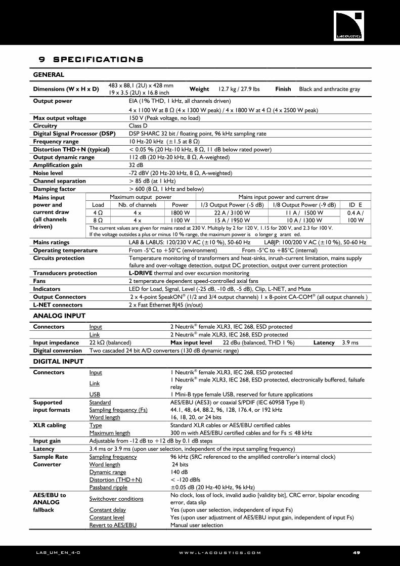
LA8_UM_EN_4-0 www . l - a co ust i c s . c o m 49494949
9999 SPECIFICATIONSSPECIFICATIONSSPECIFICATIONSSPECIFICATIONS
GENERAL
Dimensions (W x H x D) 483 x 88,1 (2U) x 428 mm 19 x 3.5 (2U) x 16.8 inch
Weight 12.7 kg / 27.9 lbs Finish Black and anthracite gray
Output power EIA (1% THD, 1 kHz, all channels driven)
4 x 1100 W at 8 Ω (4 x 1300 W peak) / 4 x 1800 W at 4 Ω (4 x 2500 W peak)
Max output voltage 150 V (Peak voltage, no load)
Circuitry Class D
Digital Signal Processor (DSP) DSP SHARC 32 bit / floating point, 96 kHz sampling rate
Frequency range 10 Hz-20 kHz (±1.5 at 8 Ω)
Distortion THD+N (typical) < 0.05 % (20 Hz-10 kHz, 8 Ω, 11 dB below rated power)
Output dynamic range 112 dB (20 Hz-20 kHz, 8 Ω, A-weighted)
Amplification gain 32 dB
Noise level -72 dBV (20 Hz-20 kHz, 8 Ω, A-weighted)
Channel separation > 85 dB (at 1 kHz)
Damping factor > 600 (8 Ω, 1 kHz and below)
Mains input
power and
current draw
(all channels driven)
Maximum output power Mains input power and current draw
Load Nb. of channels Power 1/3 Output Power (-5 dB) 1/8 Output Power (-9 dB) ID E
4 Ω 4 x 1800 W 22 A / 3100 W 11 A / 1500 W 0.4 A / 100 W 8 Ω 4 x 1100 W 15 A / 1950 W 10 A / 1300 W
The current values are given for mains rated at 230 V. Multiply by 2 for 120 V, 1.15 for 200 V, and 2.3 for 100 V. If the voltage outsides a plus or minus 10 % range, the maximum power is o longer g arant ed.
Mains ratings LA8 & LA8US: 120/230 V AC (±10 %), 50-60 Hz LA8JP: 100/200 V AC (±10 %), 50-60 Hz
Operating temperature From -5°C to +50°C (environment) From -5°C to +85°C (internal)
Circuits protection Temperature monitoring of transformers and heat-sinks, inrush-current limitation, mains supply failure and over-voltage detection, output DC protection, output over current protection
Transducers protection L-DRIVE thermal and over excursion monitoring
Fans 2 temperature dependent speed-controlled axial fans
Indicators LED for Load, Signal, Level (-25 dB, -10 dB, -5 dB), Clip, L-NET, and Mute
Output Connectors 2 x 4-point SpeakON® (1/2 and 3/4 output channels) 1 x 8-point CA-COM® (all output channels )
L-NET connectors 2 x Fast Ethernet RJ45 (in/out)
ANALOG INPUT
Connectors Input 2 Neutrik® female XLR3, IEC 268, ESD protected
Link 2 Neutrik® male XLR3, IEC 268, ESD protected
Input impedance 22 kΩ (balanced) Max input level 22 dBu (balanced, THD 1 %) Latency 3.9 ms
Digital conversion Two cascaded 24 bit A/D converters (130 dB dynamic range)
DIGITAL INPUT
Connectors Input 1 Neutrik® female XLR3, IEC 268, ESD protected
Link 1 Neutrik® male XLR3, IEC 268, ESD protected, electronically buffered, failsafe relay
USB 1 Mini-B type female USB, reserved for future applications
Supported Standard AES/EBU (AES3) or coaxial S/PDIF (IEC 60958 Type II)
input formats Sampling frequency (Fs) 44.1, 48, 64, 88.2, 96, 128, 176.4, or 192 kHz
Word length 16, 18, 20, or 24 bits
XLR cabling Type Standard XLR cables or AES/EBU certified cables
Maximum length 300 m with AES/EBU certified cables and for Fs ≤ 48 kHz
Input gain Adjustable from -12 dB to +12 dB by 0.1 dB steps
Latency 3.4 ms or 3.9 ms (upon user selection, independent of the input sampling frequency)
Sample Rate Sampling frequency 96 kHz (SRC referenced to the amplified controller’s internal clock)
Converter Word length 24 bits
Dynamic range 140 dB
Distortion (THD+N) < -120 dBfs
Passband ripple ±0.05 dB (20 Hz-40 kHz, 96 kHz)
AES/EBU to ANALOG
Switchover conditions No clock, loss of lock, invalid audio [validity bit], CRC error, bipolar encoding error, data slip
fallback Constant delay Yes (upon user selection, independent of input Fs)
Constant level Yes (upon user adjustment of AES/EBU input gain, independent of input Fs)
Revert to AES/EBU Manual user selection
LALALALA8888 AMPLIFIED CONTROLLERAMPLIFIED CONTROLLERAMPLIFIED CONTROLLERAMPLIFIED CONTROLLER USER MANUALUSER MANUALUSER MANUALUSER MANUAL VERSION 4.0
LA8_UM_EN_4-0 www . l - a co ust i c s . c o m 50505050
10101010 APPENDIX: PROTECTION SYSTEMSAPPENDIX: PROTECTION SYSTEMSAPPENDIX: PROTECTION SYSTEMSAPPENDIX: PROTECTION SYSTEMS
10.1 Amplified controller protection systems
Most of the protection systems that ensure the integrity of the unit’s electronic vital parts are managed by the Operating System (OS). This allows real-time monitoring and optimal performance with a high level of safety even under extreme conditions. 10.1.1 Thermal Protection
The fans associated to the heat sinks operate permanently, but as long as the temperature remains below 40 °C they run at their slowest speed and can hardly be heard. The highest detected temperature controls the speed of the fans. Above 40 °C the speed is increased until it reaches its maximum value.
If the OS detects a temperature of more than 85 °C at the heat sinks the input signals delivered at all amplifier output channels are attenuated. The input signal is muted if the temperature exceeds 96 °C. 10.1.2 Mean Over-Current Protection - Fuse Protection
The average mains current can peak temporarily depending on load impedance and type of signal, at values several times higher than the nominal value supported by the fuse protection. In order to avoid shut-down of the power supply (due to the over-current protection of the SMPS controller) the amplitude of the input signals will be limited. 10.1.3 DC Protection
Each of the four amplifier channel outputs is monitored at all time for sustained presence of DC voltage above the 3 V threshold. If such threshold is exceeded for a long time the concerned output channel will be automatically switched off. 10.1.4 Mains supply Under & Over-voltage Detection
The LA8 amplified controller uses an auto-sensing SMPS for mains input voltages 120/230 V (LA8 or LA8US) or 100/200 V (LA8JP). The mains supply voltage is monitored at all times for under and over-voltage: the auto-sensing SMPS will automatically switch off if the mains supply voltage leaves the nominal voltage window.
When the mains supply voltage returns to an acceptable value a soft start sequence will be automatically engaged. 10.1.5 Mains supply Failure Detection
The mains supply is monitored at all times for mains cycles discontinuity. If the mains supply skips about 2 cycles the auto-sensing SMPS will switch off. A soft start sequence will be automatically engaged when the mains supply returns to nominal state. 10.1.6 Peak Over-Current Protection
The amplified controller main SMPS current is continuously monitored. If an over-current is detected the main SMPS is immediately switched off. Should there be an internal failure this feature prevents other parts from being damaged.
The output stages also are continuously monitored for possible current surges. There are two limiting levels of over-current depending on output voltage (limitation will be set automatically). This approach improves reliability without degrading sound quality. 10.2 L-DRIVE transducer protection system
The L-DRIVE transducer protection system provides a dual analysis of both signal intensity and voltage in real-time and RMS. Under extreme conditions, when component membranes reach the over-excursion zone or if the coil ensemble temperature reaches a critical point, L-DRIVE is activated and acts as a power regulator.
As a result, the amount of power delivered to each channel is adjusted to the power handling capacity of each individual transducer on the relevant channel. Thereby, this optimizes the power resources of the system in use while preserving the highest available dynamic range.

w ww . l - a c o u s t i c s . co m

w ww . l - a c o u s t i c s . co m
LA4 LA4 LA4 LA4 CONTROLEUR AMPLIFIECONTROLEUR AMPLIFIECONTROLEUR AMPLIFIECONTROLEUR AMPLIFIE

w ww . l - a c o u s t i c s . co m
Document reference: LA8_UM_EN_4-0
Distribution date: April 29th, 2011
© 2011 L-ACOUSTICS®. All rights reserved. No part of this publication may be reproduced or transmitted in any form or by any means without the express written consent of the publisher.
Printed on recycled paper


![(19) United States (12) Patent Application Publication (10 ...large.stanford.edu/courses/2014/ph240/gerrard1/docs/US201302211… · [0005] CrossWind kite systems comprising tethered](https://img.pdfslide.net/doc/110x75/5f08396c7e708231d420f381/19-united-states-12-patent-application-publication-10-large-0005-crosswind.jpg)