Embed Size (px)
Citation preview
SKR
Catalog No. 309-1E
LM Guide Actuators FeaturingCaged Ball TechnologyCaged Ball Technology OffersLong life and long-term, maintenance-free operationExcellent high speed performanceReduced variations in rolling resistance and low noise
This catalog use non-chlorine bleached paper thatproduces no dioxin.
NEW
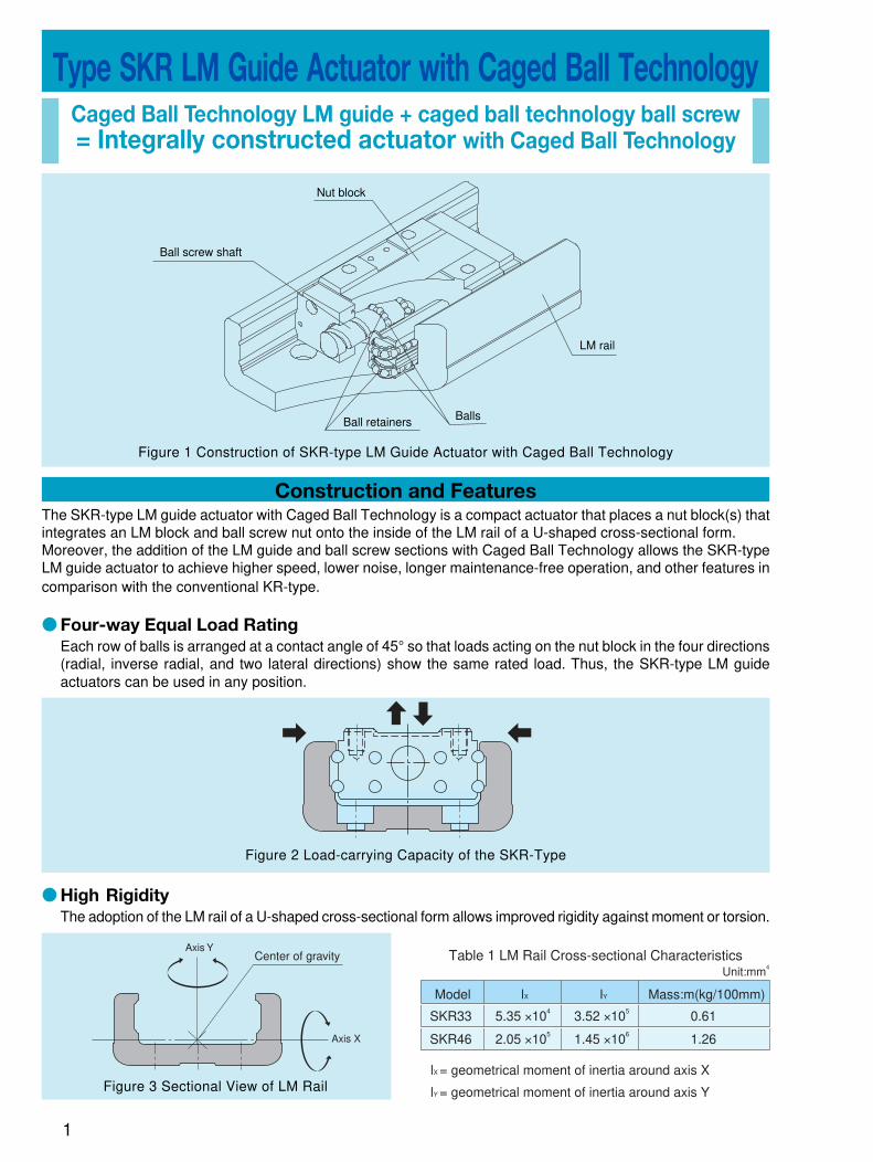
Type SKR LM Guide Actuator with Caged Ball TechnologyCaged Ball Technology LM guide + caged ball technology ball screw= Integrally constructed actuator with Caged Ball Technology
Construction and Features
1
Nut block
Ball screw shaft
Ball retainers Balls
LM rail
Figure 1 Construction of SKR-type LM Guide Actuator with Caged Ball Technology
The SKR-type LM guide actuator with Caged Ball Technology is a compact actuator that places a nut block(s) thatintegrates an LM block and ball screw nut onto the inside of the LM rail of a U-shaped cross-sectional form.Moreover, the addition of the LM guide and ball screw sections with Caged Ball Technology allows the SKR-typeLM guide actuator to achieve higher speed, lower noise, longer maintenance-free operation, and other features incomparison with the conventional KR-type.
● Four-way Equal Load Rating
Each row of balls is arranged at a contact angle of 45° so that loads acting on the nut block in the four directions(radial, inverse radial, and two lateral directions) show the same rated load. Thus, the SKR-type LM guideactuators can be used in any position.
Figure 2 Load-carrying Capacity of the SKR-Type
● High Rigidity
The adoption of the LM rail of a U-shaped cross-sectional form allows improved rigidity against moment or torsion.
Center of gravityAxis Y
Axis X
Figure 3 Sectional View of LM Rail
Model
SKR33
SKR46
5.35 ×10⁴
2.05 ×10⁵
3.52 ×10⁵
1.45 ×10⁶
0.61
1.26
lX lY Mass:m(kg/100mm)
Unit:mm4
Table 1 LM Rail Cross-sectional Characteristics
lX = geometrical moment of inertia around axis X
lY = geometrical moment of inertia around axis Y
2
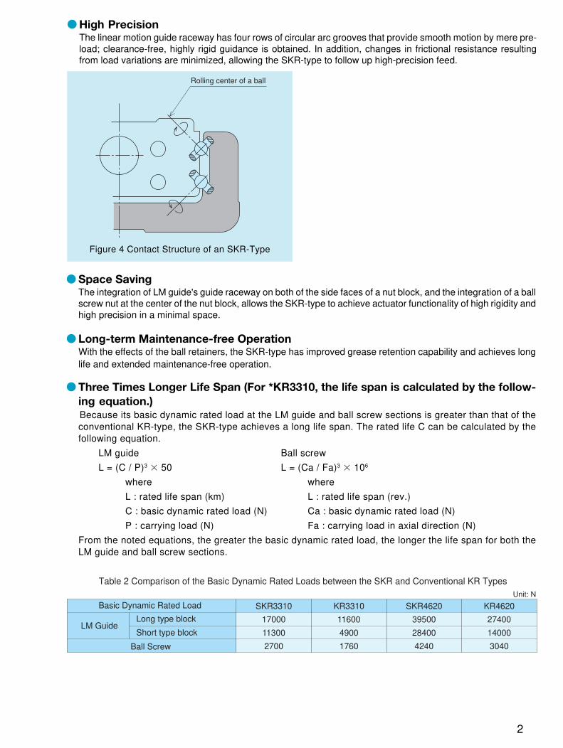
● High PrecisionThe linear motion guide raceway has four rows of circular arc grooves that provide smooth motion by mere pre-load; clearance-free, highly rigid guidance is obtained. In addition, changes in frictional resistance resultingfrom load variations are minimized, allowing the SKR-type to follow up high-precision feed.
Rolling center of a ball
Figure 4 Contact Structure of an SKR-Type
● Space SavingThe integration of LM guide's guide raceway on both of the side faces of a nut block, and the integration of a ballscrew nut at the center of the nut block, allows the SKR-type to achieve actuator functionality of high rigidity andhigh precision in a minimal space.
● Long-term Maintenance-free OperationWith the effects of the ball retainers, the SKR-type has improved grease retention capability and achieves longlife and extended maintenance-free operation.
● Three Times Longer Life Span (For *KR3310, the life span is calculated by the follow-
ing equation.)Because its basic dynamic rated load at the LM guide and ball screw sections is greater than that of theconventional KR-type, the SKR-type achieves a long life span. The rated life C can be calculated by thefollowing equation.
LM guide Ball screw
L = (C / P)3 � 50 L = (Ca / Fa)3 � 106
where where
L : rated life span (km) L : rated life span (rev.)
C : basic dynamic rated load (N) Ca : basic dynamic rated load (N)
P : carrying load (N) Fa : carrying load in axial direction (N)
From the noted equations, the greater the basic dynamic rated load, the longer the life span for both theLM guide and ball screw sections.
SKR3310
17000
11300
2700
KR4620
27400
14000
3040
SKR4620
39500
28400
4240
KR3310
11600
4900
1760
Table 2 Comparison of the Basic Dynamic Rated Loads between the SKR and Conventional KR TypesUnit: N
Basic Dynamic Rated Load
LM GuideLong type block
Short type block
Ball Screw
3
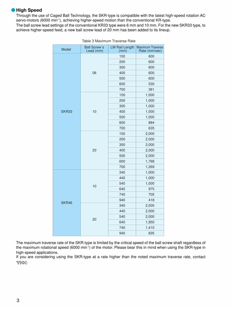
● High SpeedThrough the use of Caged Ball Technology, the SKR-type is compatible with the latest high-speed rotation ACservo-motors (6000 min-1), achieving higher-speed motion than the conventional KR-type.The ball screw lead settings of the conventional KR33 type were 6 mm and 10 mm. For the new SKR33 type, toachieve higher-speed feed, a new ball screw lead of 20 mm has been added to its lineup.
SKR33
SKR46
06
10
20
10
20
150
200
300
400
500
600
700
150
200
300
400
500
600
700
150
200
300
400
500
600
700
340
440
540
640
740
940
340
440
540
640
740
940
600
600
600
600
600
530
381
1,000
1,000
1,000
1,000
1,000
884
635
2,000
2,000
2,000
2,000
2,000
1,768
1,269
1,000
1,000
1,000
975
705
418
2,000
2,000
2,000
1,950
1,410
835
Table 3 Maximum Traverse Rate
ModelBall Screw´s Lead (mm)
LM Rail Length (mm)
Maximum Traverse Rate (mm/sec)
The maximum traverse rate of the SKR-type is limited by the critical speed of the ball screw shaft regardless ofthe maximum rotational speed (6000 min-1) of the motor. Please bear this in mind when using the SKR-type inhigh-speed applications.If you are considering using the SKR-type at a rate higher than the noted maximum traverse rate, contact
.
4
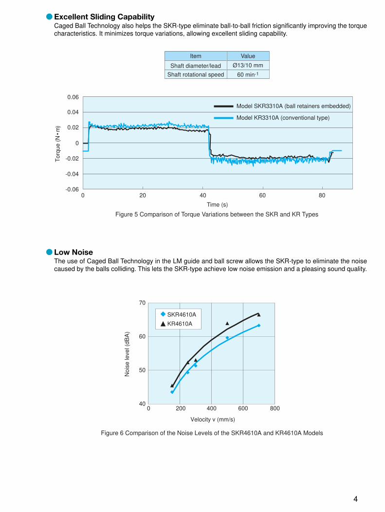
● Excellent Sliding CapabilityCaged Ball Technology also helps the SKR-type eliminate ball-to-ball friction significantly improving the torquecharacteristics. It minimizes torque variations, allowing excellent sliding capability.
0 20 40 60 80
0.06
0.04
0.02
0
-0.02
-0.04
-0.06
60 min-1
Item Value
Shaft diameter/lead Ø13/10 mm
Shaft rotational speed
Figure 5 Comparison of Torque Variations between the SKR and KR Types
Time (s)
Tor
que
(N •
m)
Model SKR3310A (ball retainers embedded)
Model KR3310A (conventional type)
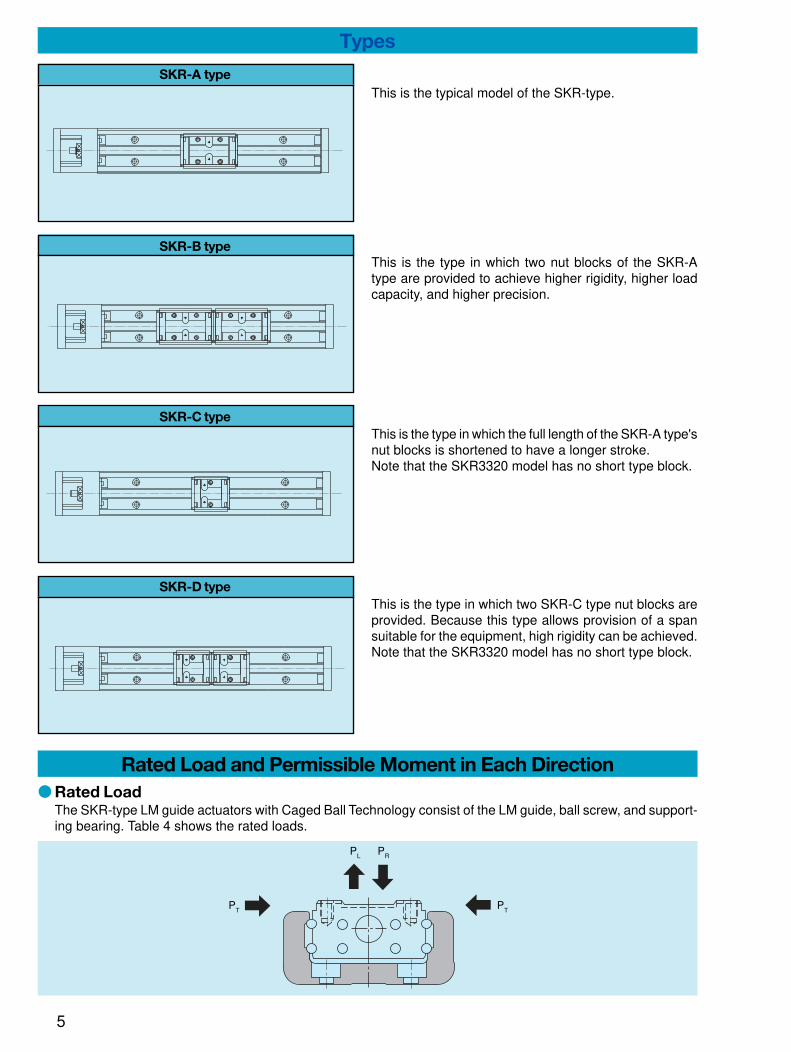
● Low NoiseThe use of Caged Ball Technology in the LM guide and ball screw allows the SKR-type to eliminate the noisecaused by the balls colliding. This lets the SKR-type achieve low noise emission and a pleasing sound quality.
SKR4610A
KR4610A
70
60
50
400 200 400 600 800
Noi
se le
vel (
dBA
)
Velocity v (mm/s)
Figure 6 Comparison of the Noise Levels of the SKR4610A and KR4610A Models
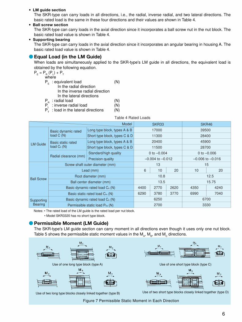
Types
SKR-A type
SKR-B type
SKR-C type
SKR-D type
This is the typical model of the SKR-type.
This is the type in which two nut blocks of the SKR-Atype are provided to achieve higher rigidity, higher loadcapacity, and higher precision.
This is the type in which the full length of the SKR-A type'snut blocks is shortened to have a longer stroke.Note that the SKR3320 model has no short type block.
This is the type in which two SKR-C type nut blocks areprovided. Because this type allows provision of a spansuitable for the equipment, high rigidity can be achieved.Note that the SKR3320 model has no short type block.
Rated Load and Permissible Moment in Each Direction
● Rated LoadThe SKR-type LM guide actuators with Caged Ball Technology consist of the LM guide, ball screw, and support-ing bearing. Table 4 shows the rated loads.
PT PT
PL PR
5
• LM guide section
The SKR-type can carry loads in all directions, i.e., the radial, inverse radial, and two lateral directions. Thebasic rated load is the same in these four directions and their values are shown in Table 4.
• Ball screw section
The SKR-type can carry loads in the axial direction since it incorporates a ball screw nut in the nut block. Thebasic rated load value is shown in Table 4.
• Supporting bearing
The SKR-type can carry loads in the axial direction since it incorporates an angular bearing in housing A. Thebasic rated load value is shown in Table 4.
● Equal Load (in the LM Guide)When loads are simultaneously applied to the SKR-type's LM guide in all directions, the equivalent load isobtained by the following equation.P
E = P
R (P
L) + P
TwhereP
E: equivalent load (N)
In the radial directionIn the inverse radial directionIn the lateral directions
PR
: radial load (N)P
L: inverse radial load (N)
PT
: load in the lateral directions (N)
SKR33
17000
11300
20400
11500
0 to –0.004
–0.004 to –0.012
13
6 10 20
10.8
13.5
4400 2770 2620
6290 3780 3770
6250
2700
SKR46
39500
28400
45900
28700
0 to –0.006
–0.006 to –0.016
15
10 20
12.5
15.75
4350 4240
6990 7040
6700
3330
Table 4 Rated Loads
Model
LM Guide
Basic dynamic rated load C (N)
Long type block, types A & B
Short type block, types C & D
Long type block, types A & B
Short type block, types C & DBasic static rated load C0 (N)
Radial clearance (mm) Standard/high quality
Precision quality
Ball Screw
Screw shaft outer diameter (mm)
Lead (mm)
Root diameter (mm)
Ball center diameter (mm)
Basic dynamic rated load Ca (N)
Basic static rated load C0a (N)
Basic dynamic rated load Ca (N)
Permissible static load P0a (N)Supporting
Bearing
● Permissible Moment (LM Guide)The SKR-type's LM guide section can carry moment in all directions even though it uses only one nut block.Table 5 shows the permissible static moment values in the M
A, M
B, and M
C directions.
Figure 7 Permissible Static Moment in Each Direction
Use of one long type block (type A)
Use of two long type blocks closely linked together (type B)
Use of one short type block (type C)
Use of two short type blocks closely linked together (type D)
Notes: • The rated load of the LM guide is the rated load per nut block.
• Model SKR3320 has no short type block.
6
7
SKR33 - A
SKR33 - B
SKR33 - C
SKR33 - D
SKR46 - A
SKR46 - B
SKR46 - C
SKR46 - D
173
990
58
390
579
3240
236
1460
173
990
58
390
579
3240
236
1460
424
848
240
480
1390
2780
870
1740
MA MB MC
Table 5 Permissible Static Moment Unit: N·m
ModelPermissible Static Moment
Note 1: Symbol A, B, C, or D at the end of the model number represents the type of nut block and the number of them in use.A: long type block, one piece used B: long type block, two pieces closely linked together C: short type block, one piece used D: short type block, two pieces closely linked together
Note 2: The permissible static moment for the SKR-B or -D type shows a value applicable when two nut blocks are used and closely linked together.
Life SpanThe SKR-type LM guide actuator with Caged Ball Technology consists of the LM guide, ball screw, and supportingbearing. The life span of each constituting component can be calculated based on the basic dynamic rated loadshown in Rated Loads (Table 4 on p. 6).
● Calculation of Life Span
1) LM Guide
■ Rated Life Span
The rated life span (L) refers to the total traveling distance that 90% of a group of the same LM guides canachieve without flaking (flakes peeling off the metal surface) when these LM guides are individually movedunder the same conditions.The rated life span of the LM guide can be obtained by equation (1).
(1)L = 3
× 50fC
• CfW
• PC
whereL : rated life span (km)C : basic dynamic rated load (N)Pc : calculated carrying load (N)fw : load factor (see Table 7)fc : contact factor (see Table 6)
• If moment is acted on the SKR-type when using the SKR-A/-C type or the SKR-B/-D type of closely linked doublenut blocks, multiply the acting moment by the equivalent coefficient shown in Table 8 to calculate equivalent load.
Pm = K � M
where Pm : Equivalent load (per block) (N) K : Moment-equivalent factor M : Operating moment (N�mm) (If the SKR-type is used using three or more nut blocks or with the span separated, contact .)In particular, if moment MC acts on the SKR-B or -D type, use the following equation to obtain the equivalent load:
PmPP = KC � MC
2• If radial load (P) and moment act on the SKR-type simultaneously, use the following equation to calculate the life span: P
E = Pm + P
where PE : Total equivalent radial load (N)
■ Life SpanWhen the rated life span (L) is obtained, the life span can be obtained by equation (2) if the stroke length andthe number of back and forth motions are constant.
Lh =L � 106
2 � S � 1 � 60(2)
whereLh : life span (h)�s : stroke length (mm)n1 : number of back and forth motions per minute (min-1)
8
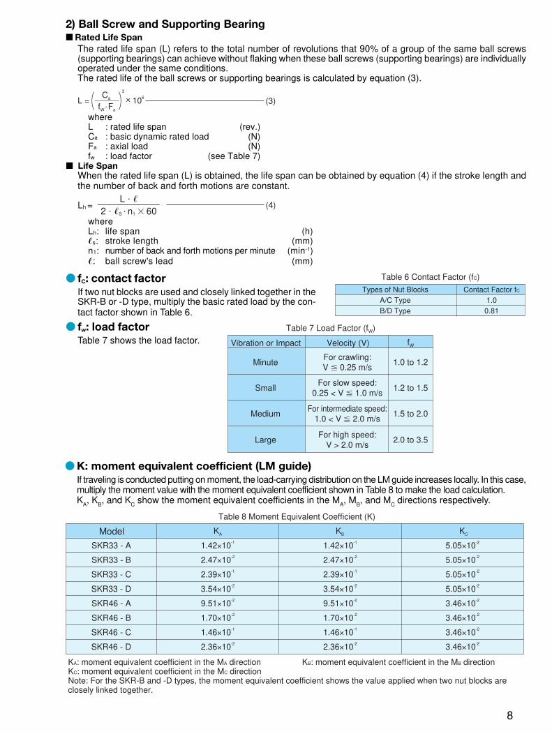
2) Ball Screw and Supporting Bearing■ Rated Life Span
The rated life span (L) refers to the total number of revolutions that 90% of a group of the same ball screws(supporting bearings) can achieve without flaking when these ball screws (supporting bearings) are individuallyoperated under the same conditions.The rated life of the ball screws or supporting bearings is calculated by equation (3).
(3)L = 3
× 106
Ca
fW • Fa
whereL : rated life span (rev.)Ca : basic dynamic rated load (N)Fa : axial load (N)fw : load factor (see Table 7)
■ Life SpanWhen the rated life span (L) is obtained, the life span can be obtained by equation (4) if the stroke length andthe number of back and forth motions are constant.
Lh =L � �
2 � �S � n1 � 60(4)
whereLh: life span (h)�s: stroke length (mm)n1: number of back and forth motions per minute (min-1)�: ball screw's lead (mm)
● fC: contact factor
If two nut blocks are used and closely linked together in theSKR-B or -D type, multiply the basic rated load by the con-tact factor shown in Table 6.
● fw: load factor
Table 7 shows the load factor.
1.0
0.81
Table 6 Contact Factor (fC)
Types of Nut Blocks
A/C Type
B/D Type
Contact Factor fC
Table 7 Load Factor (fW)
Vibration or Impact Velocity (V) fW
Minute
Small
Medium
Large
For crawling:V � 0.25 m/s
For slow speed:0.25 < V � 1.0 m/s
For intermediate speed:1.0 < V � 2.0 m/s
For high speed:V > 2.0 m/s
1.0 to 1.2
2.0 to 3.5
1.5 to 2.0
1.2 to 1.5
SKR33 - A
SKR33 - B
SKR33 - C
SKR33 - D
SKR46 - A
SKR46 - B
SKR46 - C
SKR46 - D
1.42×10⁻¹
2.47×10⁻²
2.39×10⁻¹
3.54×10⁻²
9.51×10⁻²
1.70×10⁻²
1.46×10⁻¹
2.36×10⁻²
1.42×10⁻¹
2.47×10⁻²
2.39×10⁻¹
3.54×10⁻²
9.51×10⁻²
1.70×10⁻²
1.46×10⁻¹
2.36×10⁻²
5.05×10⁻²
5.05×10⁻²
5.05×10⁻²
5.05×10⁻²
3.46×10⁻²
3.46×10⁻²
3.46×10⁻²
3.46×10⁻²
KA KB KC
Table 8 Moment Equivalent Coefficient (K)
Model
KA: moment equivalent coefficient in the MA direction KB: moment equivalent coefficient in the MB directionKC: moment equivalent coefficient in the MC directionNote: For the SKR-B and -D types, the moment equivalent coefficient shows the value applied when two nut blocks are closely linked together.
● K: moment equivalent coefficient (LM guide)
If traveling is conducted putting on moment, the load-carrying distribution on the LM guide increases locally. In this case,multiply the moment value with the moment equivalent coefficient shown in Table 8 to make the load calculation.K
A, K
B, and K
C show the moment equivalent coefficients in the M
A, M
B, and M
C directions respectively.
9
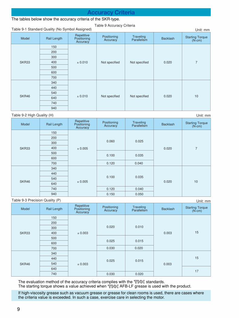
Accuracy CriteriaThe tables below show the accuracy criteria of the SKR-type.
The evaluation method of the accuracy criteria complies with the standards.The starting torque shows a value achieved when AFB-LF grease is used with the product.
If high-viscosity grease such as vacuum grease or grease for clean rooms is used, there are cases wherethe criteria value is exceeded. In such a case, exercise care in selecting the motor.
150
200
300
400
500
600
700
340
440
540
640
740
940
150
200
300
400
500
600
700
340
440
540
640
740
940
SKR33
SKR46
± 0.010
± 0.010
0.020
0.020
7
10
15
15
17
± 0.003
± 0.003
0.003
0.003
0.060
0.100
0.120
0.100
0.120
0.150
0.025
0.035
0.040
0.035
0.040
0.050
7SKR33
SKR46
± 0.005
± 0.005
0.020
0.020 10
Table 9 Accuracy CriteriaUnit: mmTable 9-1 Standard Quality (No Symbol Assigned)
Table 9-2 High Quality (H)
Model Rail LengthRepetitive Positioning Accuracy
Positioning Accuracy
Traveling Parallelism Backlash Starting Torque
(N-cm)
Unit: mm
Unit: mm
Model Rail LengthRepetitive Positioning Accuracy
Positioning Accuracy
Traveling Parallelism Backlash Starting Torque
(N-cm)
150
200
300
400
500
600
700
340
440
540
640
740
0.020
0.025
0.030
0.025
0.030
0.010
0.015
0.020
0.015
0.020
SKR33
SKR46
Model Rail LengthRepetitive Positioning Accuracy
Positioning Accuracy
Traveling Parallelism Backlash Starting Torque
(N-cm)
Not specified Not specified
Not specified Not specified
Table 9-3 Precision Quality (P)

10
SealsThe SKR-type is equipped with an end seal and a side seal as standard for dust-proofing.
0
1
0
1
2
4
5
6
7
8
9
A
B
H
P
0
1
Table 10
Accuracy Class Provision of Motor Provision of Cover Sensor Specifications
Symbol Description Symbol Description Symbol Description Symbol Description
No symbol Standardquality
Not provided
Not provided
None
With a sensor rail
Photosensor EE-SX671 (Omron)
Proximity sensor (ON if an item approaches) GL-12F(SUNX)
Proximity sensor (ON if an item approaches) GXL-N12F(SUNX)
Photosensor EE-SX674 (Omron)
Proximity sensor (ON if an item approaches) APM-D3A1(Yamatake)
Proximity sensor (ON if an item approaches) GL-N12F(SUNX)
Proximity sensor (ON if an item moves away) GL-N12FB(SUNX)
Proximity sensor (ON if an item moves away) GXL-N12FB(SUNX)
Proximity sensor (ON if an item moves away) APM-D3B1(Yamatake)
High quality
Provided Provided
Precision quality
Structure of Model Number
Side seal
End seal
1 Model number2 Ball screw's lead (mm)3 Type of nut block4 LM rail length (mm)5 Accuracy class (see Table 10)6 Provision/non-provision of a motor (see Table 10)7 Provision/non-provision of a cover (see Table 10)8 Sensor specifications (see Table 10)9 Type of housing A : 00 Type of intermediate flange (see p. 20)
Control number
1 2 3 4 5 6 7 8 9 0
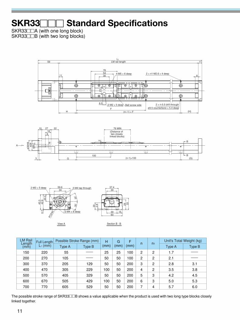
SKR33��� Standard SpecificationsSKR33��A (with one long block)SKR33��B (with two long blocks)
H�(mm)
n
150�
200�
300�
400�
500�
600�
700
220�
270�
370�
470�
570�
670�
770
55�
105�
205�
305�
405�
505�
605
�
�
129�
229�
329�
429�
529
1.7�
2.1�
2.8�
3.5�
4.2�
5.0�
5.7
�
�
3.1�
3.8�
4.5�
5.3�
6.0
25�
50�
50�
100�
50�
100�
50
G�(mm)
25�
50�
50�
50�
50�
50�
50
F�(mm)
100�
100�
200�
200�
200�
200�
200
2�
2�
3�
4�
5�
6�
7
n1
2�
2�
2�
2�
3�
3�
4
LM Rail� Length� (mm)
Full Length� L1 (mm)
Possible Stroke Range (mm)
Type A Type B Type A Type B
Unit's Total Weight (kg)
59
11 30
238.5
5476
L1
8
11
F(n1-1) × FH (H)
3
9
ø30
H8
A 8h728
271016
G100
22
2
(G)
76 MIN
B
B
PC
D400.
742
.6 20.3
59.634
30°�
30°�43
.3
2.6
6030 15
3329
37.430
20
ø9.5 counterbore × 5.4 deep
LM rail length
4-M5 × 6 deep 2 × n1-M2.6 × 4 deep
2-M2 × 5 deep Ball screw side 2 × n-5.5 drill through
(Distance of �two closely�
linked blocks)
(n-1)×100
�
ø�
ø�
2-M3 × 5 deep 2-M4 tap through
2-M4 × 8 deep
View A Section B - B
The possible stroke range of SKR33��B shows a value applicable when the product is used with two long type blocks closelylinked together.
11
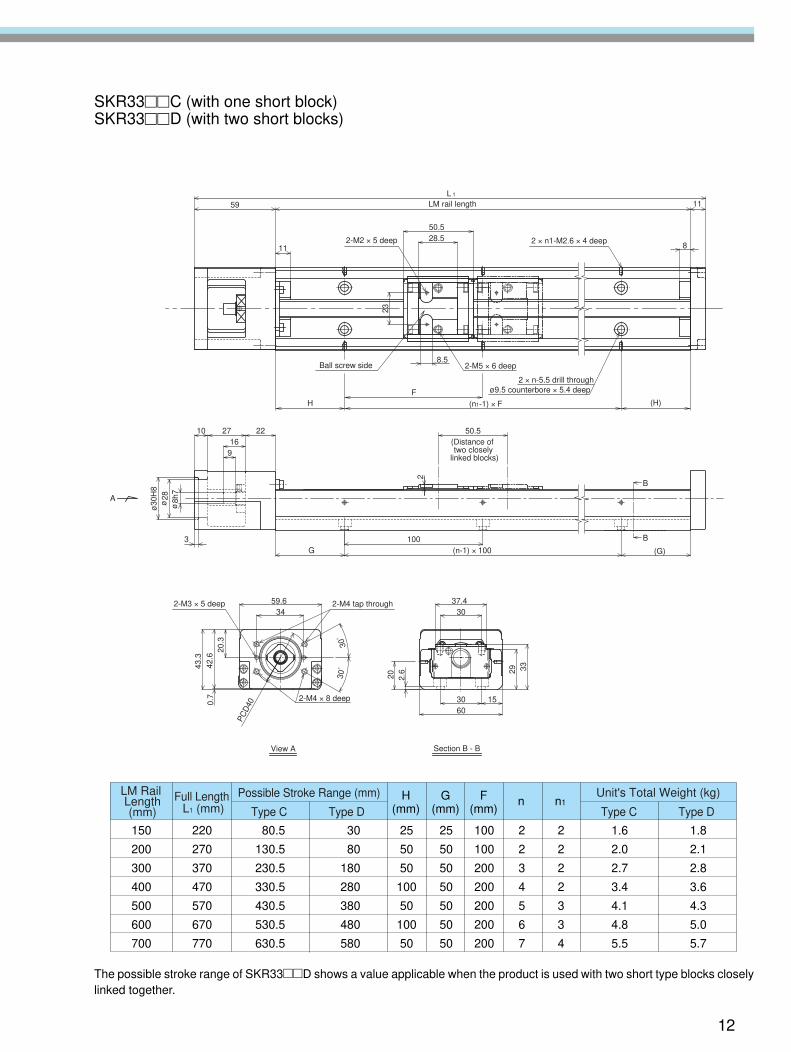
SKR33��C (with one short block)SKR33��D (with two short blocks)
59
11
8.5
28.550.5
L 1
11
23
8
HF
(H)(n1-1) × F
8h7
ø30
H8
28
3G
100
210
916
27 22
(G)
50.5
ø�ø�
B
B
A
(n-1) × 100
20.3
0.7
42.6
43.3
PC
D40
59.634
30°�
30°�
2.6
20
30
153060
29 33
37.4
LM rail length
2-M2 × 5 deep 2 × n1-M2.6 × 4 deep
Ball screw side 2-M5 × 6 deep
2 × n-5.5 drill throughø9.5 counterbore × 5.4 deep
(Distance of �two closely�
linked blocks)
2-M3 × 5 deep 2-M4 tap through
2-M4 × 8 deep
View A Section B - B
150�
200�
300�
400�
500�
600�
700
220�
270�
370�
470�
570�
670�
770
80.5�
130.5�
230.5�
330.5�
430.5�
530.5�
630.5
30�
80�
180�
280�
380�
480�
580
1.6�
2.0�
2.7�
3.4�
4.1�
4.8�
5.5
1.8�
2.1�
2.8�
3.6�
4.3�
5.0�
5.7
25�
50�
50�
100�
50�
100�
50
25�
50�
50�
50�
50�
50�
50
100�
100�
200�
200�
200�
200�
200
2�
2�
3�
4�
5�
6�
7
2�
2�
2�
2�
3�
3�
4
H�(mm)
nG�(mm)
F�(mm)
n1LM Rail� Length� (mm)
Full Length� L1 (mm)
Possible Stroke Range (mm)
Type C Type D Type C Type D
Unit's Total Weight (kg)
The possible stroke range of SKR33��D shows a value applicable when the product is used with two short type blocks closelylinked together.
12
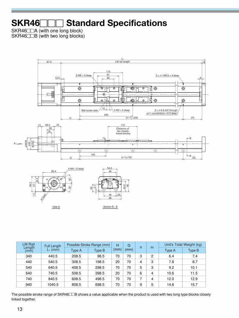
SKR46��� Standard SpecificationsSKR46��A (with one long block)SKR46��B (with two long blocks)
340�
440�
540�
640�
740�
940
440.5�
540.5�
640.5�
740.5�
840.5�
1040.5
208.5�
308.5�
408.5�
508.5�
608.5�
808.5
98.5�
198.5�
298.5�
398.5�
498.5�
698.5
6.4�
7.8�
9.2�
10.6�
12.0�
14.8
7.4�
8.7�
10.1�
11.5�
12.9�
15.7
70�
20�
70�
20�
70�
70
70�
70�
70�
70�
70�
70
3�
4�
5�
6�
7�
9
2�
3�
3�
4�
4�
5
H�(mm)
nG�(mm)
n1LM Rail� Length� (mm)
Full Length� L1 (mm)
Possible Stroke Range (mm)
Type A Type B Type A Type B
Unit's Total Weight (kg)
87.5
12.5 46
10
L1
11081
9
13
H (H)(n1-1) ×200
46
200
ø42A
ø46
H8
ø10
h7
G100
2
48.5
18
14 2528
B(G)
B
(n-1)×100
110
57.1
PCD
601.2
26.3
85.4
30°�
30°�
5.7
29
46
8646 20
40.8
54.446
58.3
LM rail length
2 × n1-M2.6 × 4 deep
2-M2 × 5 deep 2 × n-6.6 drill throughø11 counterbore × 6.5 deep
2-M6 × 9 deep
Ball screw side
(Distance of �two closely�
linked blocks)
4-M4 × 8 deep
View A Section B - B
The possible stroke range of SKR46��B shows a value applicable when the product is used with two long type blocks closelylinked together.
13
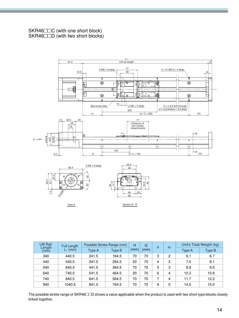
SKR46��C (with one short block)SKR46��D (with two short blocks)
10
87.5
4877
1L13
9
46
12.5
200(H)H (n1-1) × 200
A
3.5 G100
214
2818
48.5 25
B(G)
B
77
(n-1) × 100
ø46
H8
ø42
ø10
h7
46
85.4
PCD
60
1.2
58.3
26.3
57.1
40.8
4686
5.7
20
4654.4
30°�
30°�
29
View A Section B - B
4-M4 × 8 deep
LM rail length
2 × n1-M2.6 × 4 deep2-M6 × 9 deep
Ball screw side 2-M2 × 5 deep 2 × n-6.6 drill throughø11 counterbore × 6.5 deep
(Distance of �two closely�
linked blocks)
340�
440�
540�
640�
740�
940
440.5�
540.5�
640.5�
740.5�
840.5�
1040.5
241.5�
341.5�
441.5�
541.5�
641.5�
841.5
164.5�
264.5�
364.5�
464.5�
564.5�
764.5
6.1�
7.5�
8.9�
10.3�
11.7�
14.5
6.7�
8.1�
9.5�
10.8�
12.2�
15.0
70�
20�
70�
20�
70�
70
70�
70�
70�
70�
70�
70
3�
4�
5�
6�
7�
9
2�
3�
3�
4�
4�
5
H�(mm)
nG�(mm)
n1LM Rail� Length� (mm)
Full Length� L1 (mm)
Possible Stroke Range (mm)
Type A Type B Type A Type B
Unit's Total Weight (kg)
The possible stroke range of SKR46��D shows a value applicable when the product is used with two short type blocks closelylinked together.
14

SKR33��� (with the Cover)SKR33��A (with one long block)SKR33��B (with two long blocks)
150�
200�
300�
400�
500�
600�
700
220�
270�
370�
470�
570�
670�
770
55�
105�
205�
305�
405�
505�
605
�
�
129�
229�
329�
429�
529
1.9�
2.3�
3.1�
3.8�
4.6�
5.3�
6.1
�
�
3.5�
4.2�
5.0�
5.7�
6.5
25�
50�
50�
100�
50�
100�
50
25�
50�
50�
50�
50�
50�
50
100�
100�
200�
200�
200�
200�
200
2�
2�
3�
4�
5�
6�
7
2�
2�
2�
2�
3�
3�
4
H�(mm)
nG�(mm)
F�(mm)
n1LM Rail� Length� (mm)
Full Length� L1 (mm)
Possible Stroke Range (mm)
Type A Type B Type A Type B
Unit's Total Weight (kg)
305476
5
B
B
A
31
0.7
PC
D40 60
1530
2.6
20
45.5
42.3
64
(0.8
5)
34
29
59.68674
4841
30°�
30°�
Ball screw side
4-M5 × 10 deep
4-M2 × 4 deep(from the back side)
2-M4 tap through
2-M4 × 8 deep
View A Section B - B
2-M3 × 5 deep
The possible stroke range of SKR33��B shows a value applicable when the product is used with two long type blocks closelylinked together.
15

SKR33��C (with one short block)SKR33��D (with two short blocks)
5 21
28.550.5
B
B
30°�
30°�
42.3
45.5
0.7
PC
D40
30
60
86
20
34
59.6
(0.8
5)
64
7441
15
2.6
29 31
48
Ball screw side 4-M2 × 4 deep�(from the back side)�
2-M5 × 10 deep
View A Section B - B
2-M4 × 8 deep
2-M4 tap through2-M3 × 5 deep
150�
200�
300�
400�
500�
600�
700
220�
270�
370�
470�
570�
670�
770
80.5�
130.5�
230.5�
330.5�
430.5�
530.5�
630.5
30�
80�
180�
280�
380�
480�
580
1.8�
2.2�
2.9�
3.7�
4.4�
5.2�
5.9
2.0�
2.3�
3.1�
3.8�
4.6�
5.3�
6.1
25�
50�
50�
100�
50�
100�
50
25�
50�
50�
50�
50�
50�
50
100�
100�
200�
200�
200�
200�
200
2�
2�
3�
4�
5�
6�
7
2�
2�
2�
2�
3�
3�
4
H�(mm)
nG�(mm)
F�(mm)
n1LM Rail� Length� (mm)
Full Length� L1 (mm)
Possible Stroke Range (mm)
Type C Type D Type C Type D
Unit's Total Weight (kg)
The possible stroke range of SKR33��D shows a value applicable when the product is used with two short type blocks closelylinked together.
16
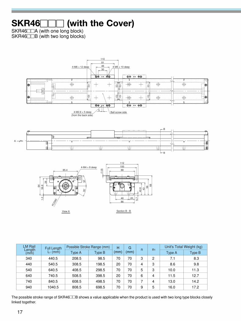
SKR46��� (with the Cover)SKR46��A (with one long block)SKR46��B (with two long blocks)
340�
440�
540�
640�
740�
940
440.5�
540.5�
640.5�
740.5�
840.5�
1040.5
208.5�
308.5�
408.5�
508.5�
608.5�
808.5
98.5�
198.5�
298.5�
398.5�
498.5�
698.5
7.1�
8.6�
10.0�
11.5�
13.0�
16.0
8.3�
9.8�
11.3�
12.7�
14.2�
17.2
70�
20�
70�
20�
70�
70
70�
70�
70�
70�
70�
70
3�
4�
5�
6�
7�
9
2�
3�
3�
4�
4�
5
H�(mm)
nG�(mm)
n1LM Rail� Length� (mm)
Full Length� L1 (mm)
Possible Stroke Range (mm)
Type A Type B Type A Type B
Unit's Total Weight (kg)
112
5
46
30
81
110
B
B
40.8 43
2046
86
5.7
88
100
56
68
1.2
56.864
PC
D60
26
85.4
A
(1.8
)
30°�
30°�
4-M6 × 12 deep 4-M5 × 10 deep
Ball screw side4-M2.6 × 5 deep(from the back side)
View A Section B - B
4-M4 × 8 deep
The possible stroke range of SKR46��B shows a value applicable when the product is used with two long type blocks closelylinked together.
17
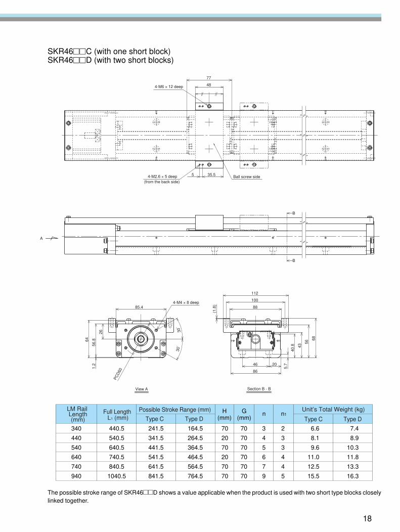
SKR46��C (with one short block)SKR46��D (with two short blocks)
35.55
48
77
B
B
A
5.7
30°�
PC
D60 86
30°�
1.2
64
56.8
26
46 20
85.4
100
(1.8
)
88
11240
.8
68
56
43
View A Section B - B
4-M6 × 12 deep
Ball screw side4-M2.6 × 5 deep(from the back side)
4-M4 × 8 deep
340
440
540
640
740
940
440.5
540.5
640.5
740.5
840.5
1040.5
241.5
341.5
441.5
541.5
641.5
841.5
164.5
264.5
364.5
464.5
564.5
764.5
6.6�
8.1�
9.6�
11.0�
12.5�
15.5
7.4
8.9
10.3
11.8
13.3
16.3
70
20
70
20
70
70
70
70
70
70
70
70
3
4
5
6
7
9
2
3
3
4
4
5
H(mm)
nG(mm)
n1LM Rail Length (mm)
Full Length L1 (mm)
Possible Stroke Range (mm)
Type C Type D Type C Type D
Unit’s Total Weight (kg)
The possible stroke range of SKR46��D shows a value applicable when the product is used with two short type blocks closelylinked together.
18

19
Sensors
● Sensors
For the SKR33 and SKR46 types, proximity sensors and photosensors are provided as options. When theSKR33 or SKR46 with sensors is specified, the sensor rails and sensor dogs specially designed for the SKR-type are also supplied with the product.• Proximity sensors GL-12F (SUNX), three units • Photosensor EE-SX671 (Omron), three units
GL-N12 F(B) (SUNX), three units EE-SX674 (Omron), three unitsGXL-N12F(B) (SUNX), three units • Connector EE-1001 (Omron), three piecesAPM-D3A1(B1) (Yamatake), three units
* The connectors are supplied with photosensors as standard.● Sensor Rails
It is also possible to install a sensor rail only.
d
b
c
a
d
b
c
a
j
g
i
h
ef
j
g
h
i
ef
Proximity sensors GL-12F, GL-N12F (B), and GXL-N12F (B) (SUNX)
Proximity sensors APM-D3A1 and APM-D3B1 (Yamatake)
Photosensor EE-SX671 (Omron)
Photosensor EE-SX674 (Omron)
SKR33�SKR46
44.7�57.7
2 �1.8
13.8�24.8
14�22
a b c dUnit: mm
Model
SKR33�SKR46
43.05�56.2
0.3�0.2
14.8�26.8
15�22
a b c dUnit: mm
Model
SKR33�SKR46
51.1�64.1
63.6�76.6
8.3�8.3
18.8�29.8
7.4�16.4
19.5�26.5
e f g h i jUnit: mm
Model
e f g h i jSKR33�SKR46
45.9�58.9
52.1�65.1
3.3�3.2
17.8�28.8
7.1�16.1
20�27
Unit: mmModel
20
Intermediate Flanges
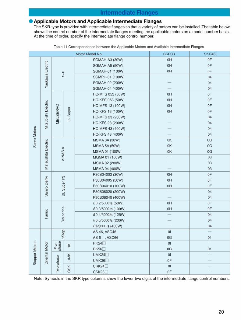
● Applicable Motors and Applicable Intermediate FlangesThe SKR-type is provided with intermediate flanges so that a variety of motors can be installed. The table belowshows the control number of the intermediate flanges meeting the applicable motors on a model number basis.At the time of order, specify the intermediate flange control number.
SKR33 SKR46
J2 S
uper
MIN
AS
Aß
is s
erie
sΣ−Π
ME
LSE
RV
O
UM
KC
SK
RK
SGMAH-A3 (30W)
SGMAH-A5 (50W)
SGMAH-01 (100W)
SGMPH-01 (100W)
SGMAH-02 (200W)
SGMAH-04 (400W)
HC-MFS 053 (50W)
HC-KFS 053 (50W)
HC-MFS 13 (100W)
HC-KFS 13 (100W)
HC-MFS 23 (200W)
HC-KFS 23 (200W)
HC-MFS 43 (400W)
HC-KFS 43 (400W)
MSMA 3A (30W)
MSMA 5A (50W)
MSMA 01 (100W)
MQMA 01 (100W)
MSMA 02 (200W)
MSMA 04 (400W)
P30B04003 (30W)
P30B04005 (50W)
P30B04010 (100W)
P30B06020 (200W)
P30B06040 (400W)
ß0.2/5000is (50W)
ß0.3/5000is (100W)
ß0.4/5000is (125W)
ß0.5/5000is (200W)
ß1/5000is (400W)
AS 46, ASC46
AS 6 , ASC66
RK54
RK56
UMK24
UMK26
CSK24
CSK26
0H
0H
0H
0H
0H
0H
0H
0K
0K
0K
0H
0H
0H
0H
0H
0I
0G
0I
0G
0I
0F
0I
0F
0F
0F
0F
04
04
04
0F
0F
0F
0F
04
04
04
04
0G
0G
0G
03
03
03
0F
0F
0F
04
04
0F
0F
04
04
04
01
01
Table 11 Correspondence between the Applicable Motors and Available Intermediate Flanges
Motor Model No.
Ser
vo M
otor
s
Yas
kaw
a E
lect
ricM
itsub
ishi
Ele
ctric
Mat
sush
ita E
lect
ricS
anyo
Den
kiF
anuc
BL
Sup
er P
3
Ste
pper
Mot
ors
Orie
ntal
Mot
or
Fiv
eph
ase
Two-
phas
e
αS
tep
Note: Symbols in the SKR type columns show the lower two digits of the intermediate flange control numbers.
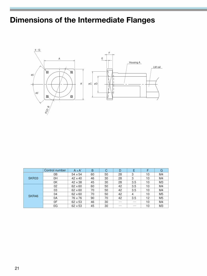
Dimensions of the Intermediate Flanges
SKR330B0H0K0203040A0F0G
54 × 5442 × 4042 × 3862 × 6062 × 6062 × 6076 × 7662 × 5362 × 53
604645607070904645
503030505050703030
28282842424242
3 3 3.53.53.54 3.5
101010101010121010
M4M4M3M4M4M5M5M4M3
SKR46
GFEDCB A × A’Control number
A
4 - G
45°
45°
A’ øC øD
E
F
PC
DB
Housing A
LM rail
21
22
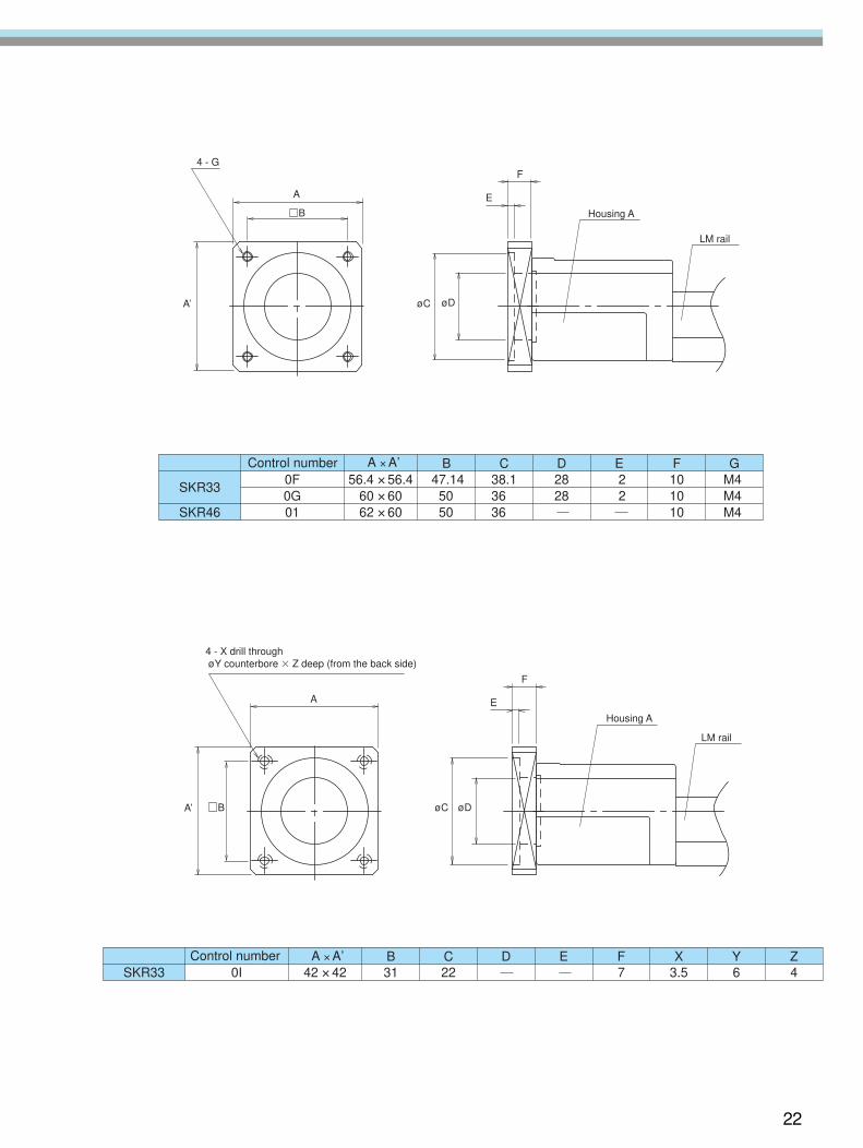
SKR33
SKR46
0F0G01
56.4 × 56.460 × 6062 × 60
47.1450 50
38.136 36
2828
22
101010
M4M4M4
GFEDCB A × A’Control number
SKR33 0I 42 × 42 31 22 7 3.5 6 4ZYXFEDCB A × A’Control number
A
B
øD
E
F4 - G
A’ øC
Housing A
LM rail
A E
F
B øDA’ øC
Housing A
LM rail
4 - X drill through øY counterbore � Z deep (from the back side)

LM-Guide Actuator SKR-type
©THK CO., LTD. 2004.6 200406000 Printed in Japan
All rights reserved.
Precautions on UseHandling
● Exercise care when handling the product. Dropping or tapping it may result in breakage.● Do not disassemble the product unless it is unavoidable. Disassembling the product unnecessarily
may result in the entry of foreign matter or cause accuracy degradation.● Operating the product exceeding the permissible revolution speed may lead to part breakage or
accidents. The operating revolution speed should be limited to the range specified by .
Operating temperature range● Do not use the product at temperatures exceeding 80°C. Should it be required to use it at 80°C or
higher, contact .
Lubrication● To deliver the full extent of SKR-type functions, lubrication is essential. Use of the product without
lubrication may result in increased abrasion at the rolling section or shorter life.● Wipe the rust-preventive oil from the product sufficiently and then fill it with lubricant before use.● Do not mix and use lubricants with different properties.● The greasing intervals differ with the operating conditions. It is recommended that the greasing
intervals be determined at the initial inspection.● If the product is used in locations constantly exposed to vibration or in special environments such as
clean rooms, vacuums, low temperatures, or high temperatures, there are cases where ordinary greasescannot be used. In such cases, contact .
Use and Lubrication in Special Environments● locations constantly exposed to vibration or in special environments such as clean rooms, vacuums,
low temperatures, or high temperatures, consult .
● “LM Guide”, “Caged Ball”, “ ” and “QZ” are the registered trademarks of THK Co., Ltd.
● There may be differences between products appearing in photographs and the actual product.● The appearance, specifications, and other information are subject to change without prior notice to
improve reliability, function, etc. When deciding to adopt the product, contact us beforehand.● We have exercised great care in preparing this catalog, but it is still possible that are misspellings,
omissions of letters, etc. assumes no responsibility or liability for damage resulting from sucherrors possibly contained herein.
● We employ the basic policy of observing the Foreign Exchange and Foreign Trade Control Law ofJapan with regard to the export of our products/technologies or sales for export. For export of ourproducts as discrete components, consult beforehand.
CHINA
BEIJINGPHONE:(10)6590-3557 FAX:(10)6590-3557
SHANGHAIPHONE:(21)6267-6571 FAX:(21)6267-6654
THK SHOUZAN CO.,LTD.PHONE:2376-1091 FAX:2376-0749
TAIWAN
TAIPEIPHONE:(02)2888-3818 FAX:(02)2888-3819
TAICHUNGPHONE:(04)2359-1505 FAX:(04)2359-1506
SOUTHERNPHONE:(06)289-7668 FAX:(06)289-7669
KOREA (SEOUL)PHONE:(02)3463-0351 FAX:(02)3017-0351
MALAYSIA (KUALA LUMPUR)PHONE:(03)9287-1137 FAX:(03)9287-8071
INDIA (BANGALORE)PHONE:(080)330-1524 FAX:(080)330-1524
NORTH AMERICA
CHICAGOPHONE:(847)310-1111 FAX:(847)310-1182
NEW JERSEYPHONE:(201)529-1950 FAX:(201)529-1962
ATLANTAPHONE:(770)840-7990 FAX:(770)840-7897
LOS ANGELESPHONE:(714)891-6752 FAX:(714)894-9315
SAN FRANCISCOPHONE:(925)455-8948 FAX:(925)455-8965
BOSTONPHONE:(781)575-1151 FAX:(781)575-9295
DETROITPHONE:(248)858-9330 FAX:(248)858-9455
INDIANAPOLISPHONE:(317)243-3496 FAX:(317)243-3499
MINNEAPOLISPHONE:(952)953-4442 FAX:(952)953-4441
TORONTOPHONE:(905)712-2922 FAX:(905)712-2925
BRASIL (SÃO PAULO)PHONE:(011)3767-0100 FAX:(011)3767-0101
EUROPE
DÜSSELDORFPHONE:0049-(0)2102-7425-0 FAX:0049-(0)2102-7425-299
STUTTGARTPHONE:0049-(0)7150-9199-0 FAX:0049-(0)7150-9199-888
MÜNCHENPHONE:0049-(0)89-370616-0 FAX:0049-(0)89-370616-26
U.K.PHONE:0044-(0)1908-222159 FAX:0044-(0)1908-222161
MILANOPHONE:0039-039-2842079 FAX:0039-039-2842527
BOLOGNAPHONE:0039-051-6412211 FAX:0039-051-6412230
SWEDENPHONE:0046-(0)8-4457630 FAX:0046-(0)8-4457639
AUSTRIAPHONE:0043-(0)7229-51400 FAX:0043-(0)7229-51400-79
SPAINPHONE:0034-93-652-5740 FAX:0034-93-652-5746
THK FRANCE S. A. S.PHONE:0033-(0)4-37491400 FAX:0033-(0)4-37491401
SOUTH AFRICA
PHONE:0027-(0)44-2720020 FAX:0027-(0)44-2720020
HEAD OFFICE 3-11-6, NISHI-GOTANDA, SHINAGAWA-KU, TOKYO 141-8503 JAPANASIA PACIFIC SALES DEPARTMENT PHONE:(03)5434-0351 FAX:(03)5434-0353

![LM Guide Actuator - tech-con.hu · A2-6 Caged Ball Technology [High Speed] Model SKR supports a latest high-rotation servomotor (6,000 min -1) by using a ball cage and is ca- pable](https://img.pdfslide.net/doc/110x75/5c95815809d3f2de7d8cb9dd/lm-guide-actuator-tech-conhu-a2-6-caged-ball-technology-high-speed-model.jpg)