Embed Size (px)
Citation preview
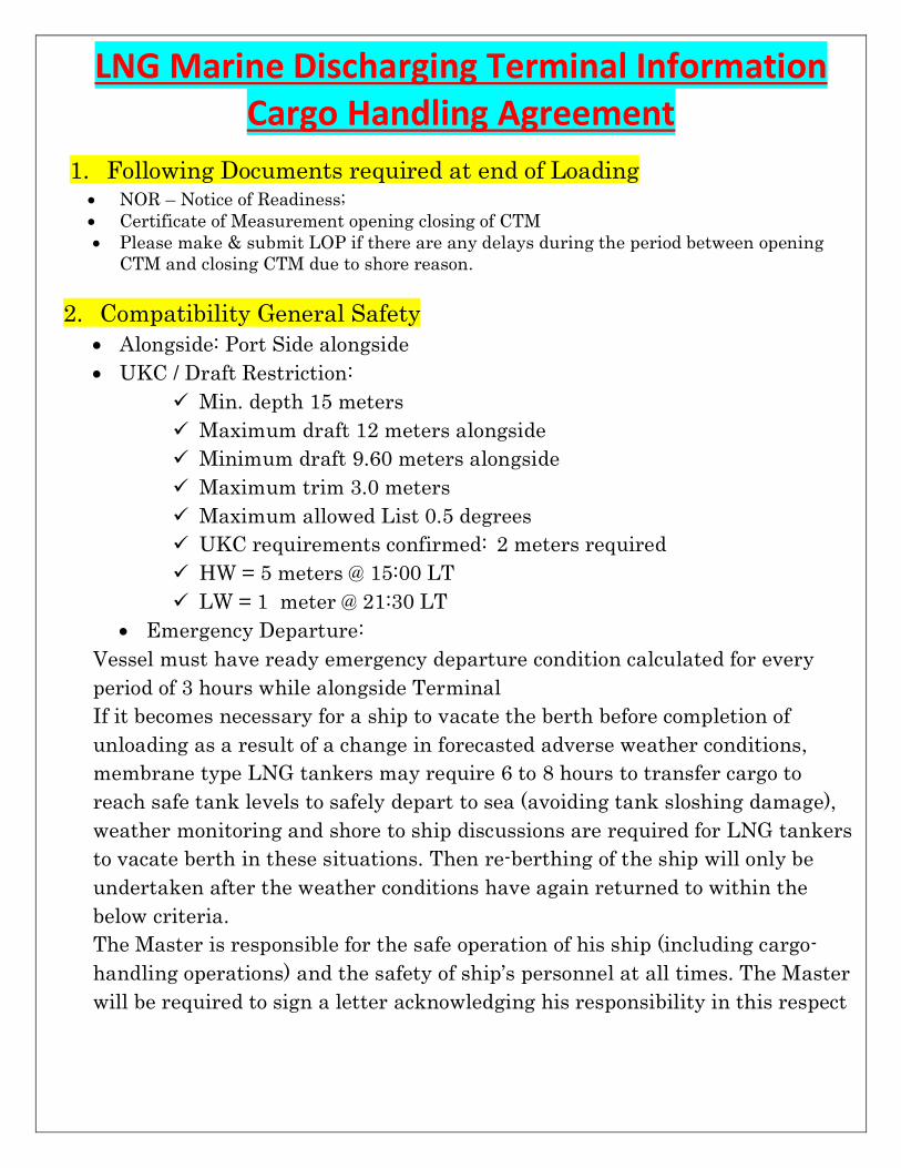
LNG Marine Discharging Terminal Information Cargo Handling Agreement
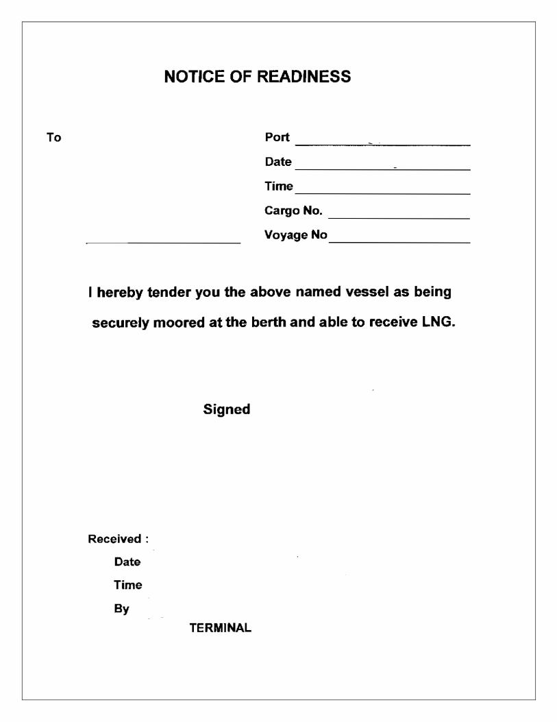
1. Following Documents required at end of Loading • NOR – Notice of Readiness; • Certificate of Measurement opening closing of CTM • Please make & submit LOP if there are any delays during the period between opening
CTM and closing CTM due to shore reason.
2. Compatibility General Safety • Alongside: Port Side alongside • UKC / Draft Restriction:
ü Min. depth 15 meters ü Maximum draft 12 meters alongside ü Minimum draft 9.60 meters alongside ü Maximum trim 3.0 meters ü Maximum allowed List 0.5 degrees ü UKC requirements confirmed: 2 meters required ü HW = 5 meters @ 15:00 LT ü LW = 1 meter @ 21:30 LT
• Emergency Departure: Vessel must have ready emergency departure condition calculated for every period of 3 hours while alongside Terminal If it becomes necessary for a ship to vacate the berth before completion of unloading as a result of a change in forecasted adverse weather conditions, membrane type LNG tankers may require 6 to 8 hours to transfer cargo to reach safe tank levels to safely depart to sea (avoiding tank sloshing damage), weather monitoring and shore to ship discussions are required for LNG tankers to vacate berth in these situations. Then re-berthing of the ship will only be undertaken after the weather conditions have again returned to within the below criteria. The Master is responsible for the safe operation of his ship (including cargo-handling operations) and the safety of ship’s personnel at all times. The Master will be required to sign a letter acknowledging his responsibility in this respect
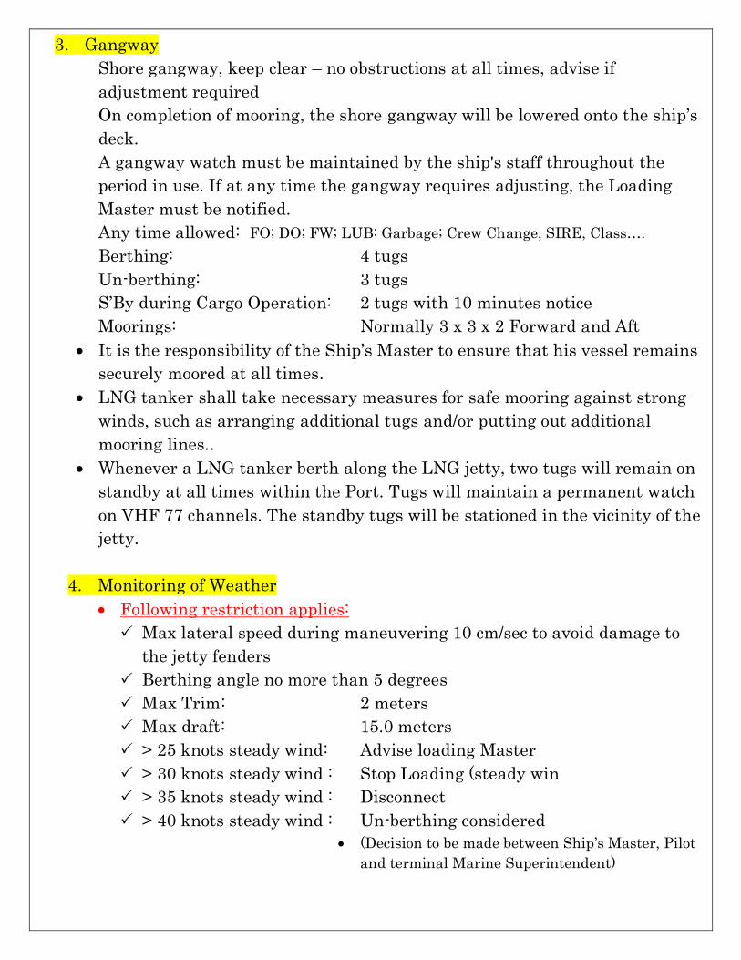
3. Gangway Shore gangway, keep clear – no obstructions at all times, advise if adjustment required On completion of mooring, the shore gangway will be lowered onto the ship’s deck. A gangway watch must be maintained by the ship's staff throughout the period in use. If at any time the gangway requires adjusting, the Loading Master must be notified. Any time allowed: FO; DO; FW; LUB: Garbage; Crew Change, SIRE, Class…. Berthing: 4 tugs Un-berthing: 3 tugs S’By during Cargo Operation: 2 tugs with 10 minutes notice Moorings: Normally 3 x 3 x 2 Forward and Aft
• It is the responsibility of the Ship’s Master to ensure that his vessel remains securely moored at all times.
• LNG tanker shall take necessary measures for safe mooring against strong winds, such as arranging additional tugs and/or putting out additional mooring lines..
• Whenever a LNG tanker berth along the LNG jetty, two tugs will remain on standby at all times within the Port. Tugs will maintain a permanent watch on VHF 77 channels. The standby tugs will be stationed in the vicinity of the jetty.
4. Monitoring of Weather • Following restriction applies: P Max lateral speed during maneuvering 10 cm/sec to avoid damage to
the jetty fenders P Berthing angle no more than 5 degrees P Max Trim: 2 meters P Max draft: 15.0 meters P > 25 knots steady wind: Advise loading Master P > 30 knots steady wind : Stop Loading (steady win P > 35 knots steady wind : Disconnect P > 40 knots steady wind : Un-berthing considered
• (Decision to be made between Ship’s Master, Pilot and terminal Marine Superintendent)
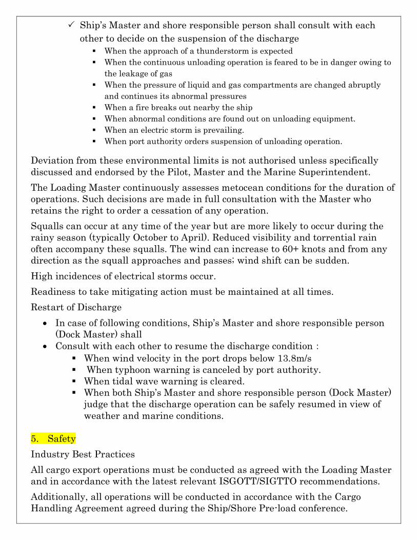
P Ship’s Master and shore responsible person shall consult with each other to decide on the suspension of the discharge § When the approach of a thunderstorm is expected § When the continuous unloading operation is feared to be in danger owing to
the leakage of gas § When the pressure of liquid and gas compartments are changed abruptly
and continues its abnormal pressures § When a fire breaks out nearby the ship § When abnormal conditions are found out on unloading equipment. § When an electric storm is prevailing. § When port authority orders suspension of unloading operation.
Deviation from these environmental limits is not authorised unless specifically discussed and endorsed by the Pilot, Master and the Marine Superintendent. The Loading Master continuously assesses metocean conditions for the duration of operations. Such decisions are made in full consultation with the Master who retains the right to order a cessation of any operation. Squalls can occur at any time of the year but are more likely to occur during the rainy season (typically October to April). Reduced visibility and torrential rain often accompany these squalls. The wind can increase to 60+ knots and from any direction as the squall approaches and passes; wind shift can be sudden. High incidences of electrical storms occur. Readiness to take mitigating action must be maintained at all times. Restart of Discharge
• In case of following conditions, Ship’s Master and shore responsible person (Dock Master) shall
• Consult with each other to resume the discharge condition: § When wind velocity in the port drops below 13.8m/s § When typhoon warning is canceled by port authority. § When tidal wave warning is cleared. § When both Ship’s Master and shore responsible person (Dock Master)
judge that the discharge operation can be safely resumed in view of weather and marine conditions.
5. Safety Industry Best Practices All cargo export operations must be conducted as agreed with the Loading Master and in accordance with the latest relevant ISGOTT/SIGTTO recommendations. Additionally, all operations will be conducted in accordance with the Cargo Handling Agreement agreed during the Ship/Shore Pre-load conference.
• Ship / Shore C/L: every 4 hours
Approved Equipment - means equipment of a design that has been tested and approved by an appropriate authority such as a Government Department or Classification Society. The authority shall have certified the equipment as safe for use in a specified hazardous atmosphere. After agreement has been reached, any deviation from the plan is not permitted without agreement of master/terminal.
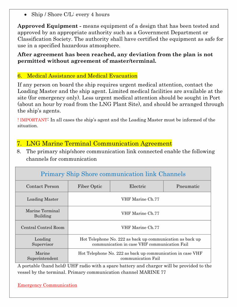
6. Medical Assistance and Medical Evacuation If any person on board the ship requires urgent medical attention, contact the Loading Master and the ship agent. Limited medical facilities are available at the site (for emergency only). Less urgent medical attention should be sought in Port (about an hour by road from the LNG Plant Site), and should be arranged through the ship’s agents. ! IMPORTANT: In all cases the ship’s agent and the Loading Master must be informed of the situation. 7. LNG Marine Terminal Communication Agreement 8. The primary ship/shore communication link connected enable the following
channels for communication
Primary Ship Shore communication link Channels
Contact Person Fiber Optic Electric Pneumatic
Loading Master VHF Marine Ch.77
Marine Terminal Building VHF Marine Ch.77
Central Control Room VHF Marine Ch.77
Loading Supervisor
Hot Telephone No. 222 as back up communication as back up communication in case VHF communication Fail
Marine Superintendent
Hot Telephone No. 222 as back up communication in case VHF communication Fail
A portable (hand held) UHF radio with a spare battery and charger will be provided to the vessel by the terminal. Primary communication channel MARINE 77 Emergency Communication
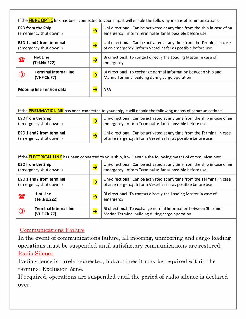
If the FIBRE OPTIC link has been connected to your ship, it will enable the following means of communications:
ESD from the Ship (emergency shut down ) → Uni-directional. Can be activated at any time from the ship in case of an
emergency. Inform Terminal as far as possible before use
ESD 1 and2 from terminal (emergency shut down ) → Uni-directional. Can be activated at any time from the Terminal in case
of an emergency. Inform Vessel as far as possible before use
( Hot Line (Tel.No.222) → Bi directional. To contact directly the Loading Master in case of
emergency
) Terminal internal line (VHF Ch.77) → Bi directional. To exchange normal information between Ship and
Marine Terminal building during cargo operation
Mooring line Tension data → N/A
If the PNEUMATIC LINK has been connected to your ship, it will enable the following means of communications:
ESD from the Ship (emergency shut down ) → Uni-directional. Can be activated at any time from the ship in case of an
emergency. Inform Terminal as far as possible before use
ESD 1 and2 from terminal (emergency shut down ) → Uni-directional. Can be activated at any time from the Terminal in case
of an emergency. Inform Vessel as far as possible before use
If the ELECTRICAL LINK has been connected to your ship, it will enable the following means of communications:
ESD from the Ship (emergency shut down ) → Uni-directional. Can be activated at any time from the ship in case of an
emergency. Inform Terminal as far as possible before use
ESD 1 and2 from terminal (emergency shut down ) → Uni-directional. Can be activated at any time from the Terminal in case
of an emergency. Inform Vessel as far as possible before use
( Hot Line (Tel.No.222) → Bi directional. To contact directly the Loading Master in case of
emergency
) Terminal internal line (VHF Ch.77) → Bi directional. To exchange normal information between Ship and
Marine Terminal building during cargo operation
Communications Failure In the event of communications failure, all mooring, unmooring and cargo loading operations must be suspended until satisfactory communications are restored. Radio Silence Radio silence is rarely requested, but at times it may be required within the terminal Exclusion Zone. If required, operations are suspended until the period of radio silence is declared over.
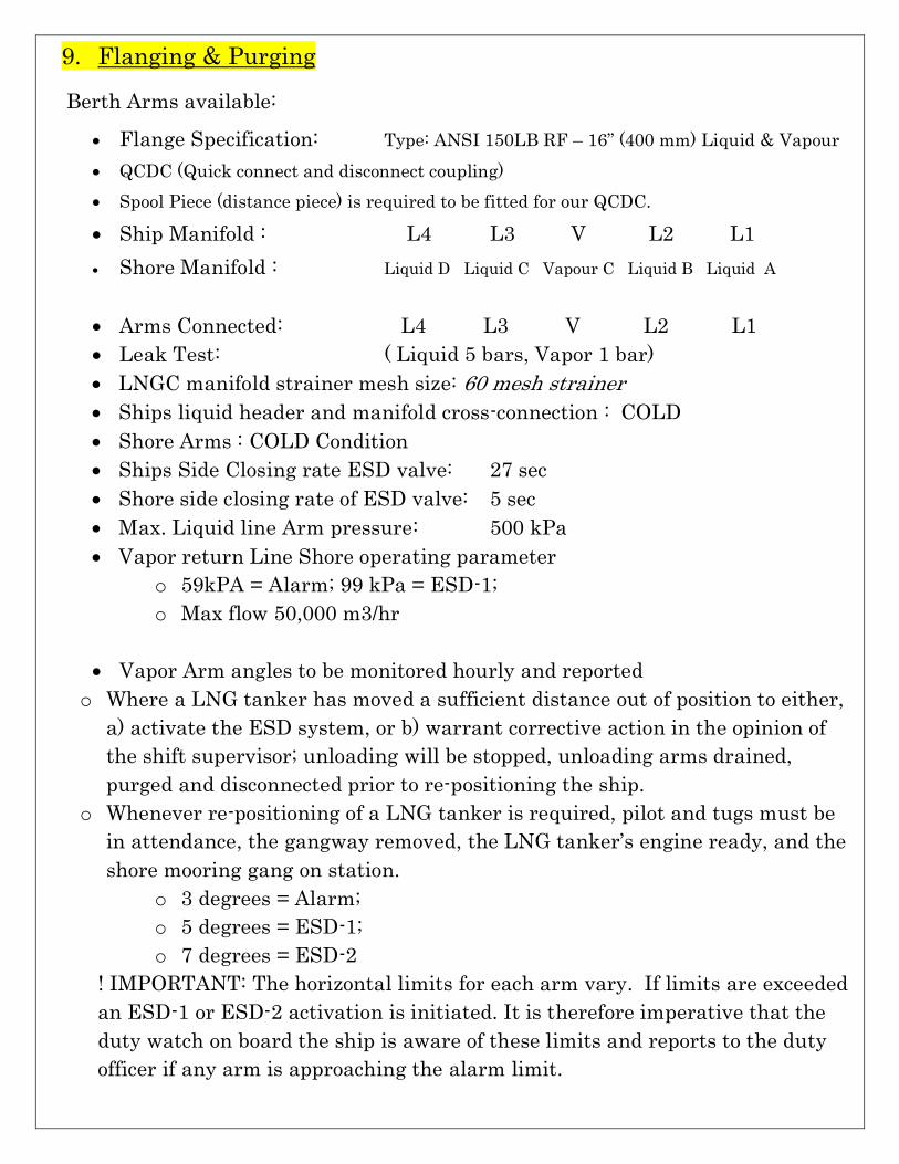
9. Flanging & Purging Berth Arms available:
• Flange Specification: Type: ANSI 150LB RF – 16” (400 mm) Liquid & Vapour • QCDC (Quick connect and disconnect coupling) • Spool Piece (distance piece) is required to be fitted for our QCDC. • Ship Manifold : L4 L3 V L2 L1 • Shore Manifold : Liquid D Liquid C Vapour C Liquid B Liquid A
• Arms Connected: L4 L3 V L2 L1 • Leak Test: ( Liquid 5 bars, Vapor 1 bar) • LNGC manifold strainer mesh size: 60 mesh strainer • Ships liquid header and manifold cross-connection : COLD • Shore Arms : COLD Condition • Ships Side Closing rate ESD valve: 27 sec • Shore side closing rate of ESD valve: 5 sec • Max. Liquid line Arm pressure: 500 kPa • Vapor return Line Shore operating parameter
o 59kPA = Alarm; 99 kPa = ESD-1; o Max flow 50,000 m3/hr
• Vapor Arm angles to be monitored hourly and reported
o Where a LNG tanker has moved a sufficient distance out of position to either, a) activate the ESD system, or b) warrant corrective action in the opinion of the shift supervisor; unloading will be stopped, unloading arms drained, purged and disconnected prior to re-positioning the ship.
o Whenever re-positioning of a LNG tanker is required, pilot and tugs must be in attendance, the gangway removed, the LNG tanker’s engine ready, and the shore mooring gang on station.
o 3 degrees = Alarm; o 5 degrees = ESD-1; o 7 degrees = ESD-2
! IMPORTANT: The horizontal limits for each arm vary. If limits are exceeded an ESD-1 or ESD-2 activation is initiated. It is therefore imperative that the duty watch on board the ship is aware of these limits and reports to the duty officer if any arm is approaching the alarm limit.
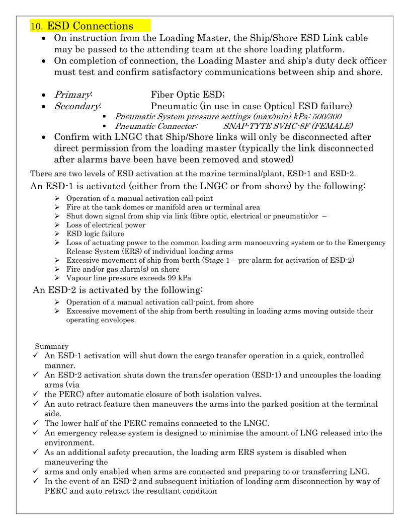
10. ESD Connections • On instruction from the Loading Master, the Ship/Shore ESD Link cable
may be passed to the attending team at the shore loading platform. • On completion of connection, the Loading Master and ship's duty deck officer
must test and confirm satisfactory communications between ship and shore.
• Primary: Fiber Optic ESD; • Secondary: Pneumatic (in use in case Optical ESD failure)
§ Pneumatic System pressure settings (max/min) kPa: 500/300 § Pneumatic Connector: SNAP-TYTE SVHC-8F (FEMALE)
• Confirm with LNGC that Ship/Shore links will only be disconnected after direct permission from the loading master (typically the link disconnected after alarms have been have been removed and stowed)
There are two levels of ESD activation at the marine terminal/plant, ESD-1 and ESD-2. An ESD-1 is activated (either from the LNGC or from shore) by the following:
Ø Operation of a manual activation call-point Ø Fire at the tank domes or manifold area or terminal area Ø Shut down signal from ship via link (fibre optic, electrical or pneumatic)or – Ø Loss of electrical power Ø ESD logic failure Ø Loss of actuating power to the common loading arm manoeuvring system or to the Emergency
Release System (ERS) of individual loading arms Ø Excessive movement of ship from berth (Stage 1 – pre-alarm for activation of ESD-2) Ø Fire and/or gas alarm(s) on shore Ø Vapour line pressure exceeds 99 kPa
An ESD-2 is activated by the following: Ø Operation of a manual activation call-point, from shore Ø Excessive movement of the ship from berth resulting in loading arms moving outside their
operating envelopes.
Summary ü An ESD-1 activation will shut down the cargo transfer operation in a quick, controlled
manner. ü An ESD-2 activation shuts down the transfer operation (ESD-1) and uncouples the loading
arms (via ü the PERC) after automatic closure of both isolation valves. ü An auto retract feature then maneuvers the arms into the parked position at the terminal
side. ü The lower half of the PERC remains connected to the LNGC. ü An emergency release system is designed to minimise the amount of LNG released into the
environment. ü As an additional safety precaution, the loading arm ERS system is disabled when
maneuvering the ü arms and only enabled when arms are connected and preparing to or transferring LNG. ü In the event of an ESD-2 and subsequent initiation of loading arm disconnection by way of
PERC and auto retract the resultant condition
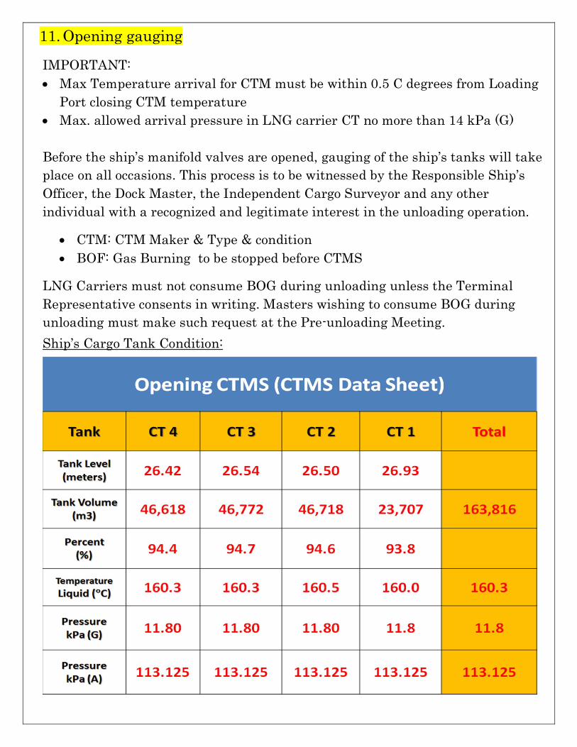
11. Opening gauging IMPORTANT: • Max Temperature arrival for CTM must be within 0.5 C degrees from Loading
Port closing CTM temperature • Max. allowed arrival pressure in LNG carrier CT no more than 14 kPa (G)
Before the ship’s manifold valves are opened, gauging of the ship’s tanks will take place on all occasions. This process is to be witnessed by the Responsible Ship’s Officer, the Dock Master, the Independent Cargo Surveyor and any other individual with a recognized and legitimate interest in the unloading operation.
• CTM: CTM Maker & Type & condition • BOF: Gas Burning to be stopped before CTMS
LNG Carriers must not consume BOG during unloading unless the Terminal Representative consents in writing. Masters wishing to consume BOG during unloading must make such request at the Pre-unloading Meeting. Ship’s Cargo Tank Condition:
12. ESD-1 Warm TEST
In addition to any tests that may be carried out by the Terminal prior to the LNG tanker’s arrival the following ESD tests shall be conducted in conjunction with each ship at the start of unloading as follows:
• Before Cooldown o Warm ESD Test – Ship – Optic
13. Cool Down of Unloading Arms The LNG tanker Cargo Control Room (CCR) shall confirm that the ship’s manifolds, liquid and vapour, are open and that they are ready to discharge product. The Terminal Control shall confirm to the LNG tanker that it is ready to commence cool-down of the loading arms.
Following the above confirmation, cooldown of loading arms will commence
Where possible the Terminal requires that LNG tanker use its spray pumps in order to avoid possible flow surges that could take place when using a Main Cargo Pump. When the LNG tanker is unable to use its spray pumps for cooling down the arms the Terminal must be advised as soon as possible before arrival. The LNG tanker is required to assure the Terminal that they will not exceed a flow rate of 50 m3/hour during the initial stages of arm cooldown. Failure to comply with this and thermal shocking of the arms with LNG in an uncontrolled manner will cause the Terminal to issue a note of protest.
Depending on the arrival condition of the LNG tanker with respect to its deck lines being in a cold or warm condition, cooldown may take longer than 1 hour. Cooldown of the arms will not be less than one hour. LNG tanker shall adjust flow and pressure to requests from the Terminal Control Room. If necessary, the Terminal can adjust the rate of arm cooldown on the jetty using bypass valves and temperature gauges to ensure that all arms are cooled down evenly together. LNG tanker should monitor closely manifold pressures during this operation.
• Shore Tank pressure: 10 kPa o (Max. allowed arrival CT pressure by Terminal regulations 14 kPa) o (Max. allowed Temp 0.5 degrees difference than loading temperature)
• S’by L/D and/or H/D compressor if required • Shore lines to be cooled down SHIP > SHORE = 80 min • Manifold pressure at beginning 1-1.5 bars (CD valve about 1 turn)
• Valves to be open under direct order from Loading Master • On completion of cooldown of the unloading arms the flow rate will be
adjusted according to the Terminal requirements for any further cooldown of shorelines
14. ESD Cold Test • On completion of cooldown a further ESD test will be carried out to confirm
closure for valves in the cold position. The ESD will be activated by Shore. On completion of the test both LNG tanker and shore will reset ESD systems.
• After Cooldown of unloading Arm o Cold ESD test – Shore – Optic
Before initiating this test both LNG tanker and shore shall confirm their readiness to each other to conduct this test.
15. Control of Return Gas to Ship.
Gas will be returned to the LNG tanker by free flow. It is the responsibility of the LNG tanker to control the quantity of gas being received and the pressure in its tanks via ship side valves. In the event that pressure in the return gas line falls to 8 Kpag or below and above 15kPag , then the ship must adjust its unloading rate until pressures return to normal levels. When pressure in the return gas line and shore tanks exceed 25 Kpag, the ESD1 will be activated, the shore pressure relief valve will lift and gas will be vented at the top of the shore tank. It is important that the Terminal Control is informed if there is any problem with the ship taking return gas in order that it can start the recondenser and monitor tank pressures During the bulk discharge of the LNG tanker, a differential pressure of 5-10 KPag must be maintained between ship tanks and shore tanks. This will be controlled by the LNG tanker via its vapour control valve and monitored hourly in the exchange of information regarding quantities, flows and pressure between ship and shore.
16. Cargo Handling Agreement • When the marine terminal and the ship are in a state or readiness to
commence loading operations, the Loading Master will give permission for the required manifold valve(s) to be opened.
• ! IMPORTANT: Once opened, the manifold valves must remain open until such time as the Loading Master instructs them to be closed.
• ! IMPORTANT: Access to the ship's manifold or underneath the loading arms at the shore operating platform is restricted during transfer of LNG and when covered in ice. • Start Discharging (Ramp Up)
• When ESD systems are reset, ship’s manifolds valves and shore valves are opened; the Terminal Control will advise the ship to start the first pump.
• 10 minutes after the first pump has started the LNG tanker will start the second pump.
• Remaining pumps will start at 5-minute intervals with LNG tanker confirming the time of each start.
• Increase of unloading rate to maximum flow rate shall be at the shore request.
• The times of starting and stopping unloading pumps shall be recorded and ship shall inform the Terminal Control on each occasion when Ramp up procedures and table will be provided by LNG tanker, discussed and agreed to during the pre-arrival meeting. However Terminal prefer 8 steps start up to be performed by ship
• Average bulk unloading rate must be in excess of 12,000 m3 /hour with a maximum manifold pressure of 0.5 Mpag.
• Max Manifold back pressure: 5 bars @ SHORE side • Max Manifold back pressure: 5 bars @ SHIP manifold • Shore LNG Quantity available for discharging: app. 200,000 m3 • Quantity Cargo onboard: 163,816 m3 • LNG Quantity required to discharge by ship : to be confirmed • Ships Pumps and Capacity: ( 8 ) x ( 1,700 m3/hr) • Shore Max Receiving Rate: 12,000 m3/hr • Ship Max Discharge Rate: 13,600 m3/hr • Discharge rate Agreed 12,000 m3/hr • Time required for Ramp Up/Down : 60 min • CONFIRM Cargo discharge Sequence Start:
• 4 steps or 8 steps • AUTO start or Manual Start • Terminal prefer 8 steps AUTO start sequence
• Degassing liquid header to prevent vapor hammering
• Any unexpected increase in back pressure at the ship manifold which may indicate possible blockage of strainers in the unloading lines will result in unloading being suspended until the cause has been ascertained and rectified.
17. During Maximum Rate • Ship/Shore Check list every 4 hours “R” code • Communication with terminal: P VHF 77
P Tel No. 222 • Max loading rate Maintain as long as possible • Following approvals required from terminal: ü Commence of De-ballasting operation, ü Draining water from deck, manifold drip tray: ü Taking stores / provision / critical repair work (start / completed )
• Additional information required to pass to Terminal: ü Radio Communication Test before start critical operation ü Before operating ESD valve / Double shut valve / cool down valve ü Before opening ESD valve / confirm OPTIC position ü After TRIP test – confirm Shore ESD is RESET before change to OPTIC ü Before Rate Up / Rate Down / FULL RATE TIME ü If changing to original plan (pump start/ h/d start…) ü Commence Ramp down ü Completion of Operation Hourly Report
• Cargo on board; Cargo to go; ETC; Average Loading rate • Vapour Header Pressure; Manifold Pressure • Wind Direction; Wind Velocity • Any abnormalities (gas/liquid leak, equipment failure…)
P Advise Terminal in case lighting in close vicinity of the Vessel
18. Completion of Loading (Ramp Down) • LNG tanker is to advise the Terminal Control one (1) hour prior to the
commencement of finishing the first cargo tank and stopping the first unloading pump.
• The ship shall give 15 minutes and 5 minutes notice to stopping of the first pump and thereafter advise the Terminal Control the time of stopping each pump until discharge is completed.
• The rate down procedures and table will be provided by LNG tanker, discussed and agreed to during the pre-arrival meeting.
o STOP Loading by SHIP Request o 15 and 5 minutes notice required before starting RAMP DOWN o Ramp Down will be conducted in steps of each pump o Ship Ramp Down Rate Required:
19. After Cargo Transfer
• Pilot will be booked 3 hours after completion of Loading - required 30 minutes notice before completion – call Agent to confirm time
20. Draining, Purging and Disconnection • On completion of unloading the shore liquid unloading arm valves will be
closed. The ship’s manifold valves should only be closed after confirmation that shore valves have been closed.
• The vapour line should remain open throughout draining and purging of liquid arms.
• The primary source of nitrogen for draining and purging of the loading arms and ships manifold will be from the terminal.
• IMPORTANT : The ship supply of nitrogen must also be available as back-up source • After competition of load and confirmation that the ships double shut valves
are closed , the terminal will drain the inboard side of the loading arms to shore (approx. 30. Min.). ü NOTE1: Ships double shut valves and all drain valves at manifold must be closed prior
to commencement of draining on shore side • The valve alignment required for draining will first be discussed and agreed
between the Loading Master (LM) and the ships representative (SR). • The loading arms will be pressurized up to 500 kPa with nitrogen, the
draining process will be coordinated by the LM and will be performed by SR .This may entrain 2-3 repeated draining cycles.
• When it is evident that the ships manifold and loading arms are drained the ship will close manifold, and where required its cool down valves as part of closing CTM process.
ü NOTE2: Typically draining of lines will take 23-30 min. ü NOTE3 : Drains or vents to the atmosphere must not be opened at this stage
• The process for purging at this terminal will be explained by the LM.This
entails’ purging N2 into ships lines and tanks
ü NOTE4 : Typically purging will commence 20-30 min.after completition of draining-dependent on weather conditions. This time is required for the loading arm DBV interlock to clear.
• The loading arm will be pressurized up to 500 kPa with nitrogen the purging process will be coordinated by the LM and performed by SR.
• This may entail repeating 2-3 times until HC content of the loading arm and manifold is less than 2% by volume.
• After 1st purge the ships drain valve will be briefly cracked open than closed to confirm that the arms and manifold is free of LNG.
• On confirmation that the loading arm and ships line is LNG free and contains less than 2%HC gas by volume. Arm disconnection will commence.
• If ship has the cool down valve located inboard of the manifold ESD valve. The LM will instruct the SR .To close manifold ESD valve(this must be closed before loading arm DBV is closed) and leave cool down valve cracked open until such time as the ESD valve is closed.
• Important: It is imperative that manifold ESD valve is closed promptly. • As soon as ESD valve is closed, the line inboard of ESD valve is to be de-
pressurized • If the ship has drain/cool down valve is located outboard of the manifold ESD
valve both valves must be closed before loading arm DBV is closed. • In this arrangement, as soon as outboard cool down line crossover valve is
closed the inboard cool down valve should be used to de-pressurize the line inboard of the ESD valve. Once depressurized it can then be closed ,for the duration of the line disconnection.
• Whichever method above is used, as soon as the ship has isolated their lines from the manifold, the terminal will immediately close loading arm DBV, depressurize the space between DBV and ESD and commence disconnection.
• This process shall be used for each loading arm as they are manually disconnected.
• Important! If there is a delay before disconnection, the loading arm and the ships line to the ESD valve will be maintained at a positive pressure, but will be depressurized prior to disconnection
21. Final gauging • Ship’s Trim and list is maintained at even keel & up-right position when final
gauging
• Vapor arm will be disconnected after gas burning started and stabilized (GCU)
22. Ship/terminal post-discharge meeting
A post-unloading meeting will be held in the Ship’s Conference Room. Dock Master or the Terminal’s Senior Duty Operator and Ship’s master and Chief Officer will attend. Any incidents or operational difficulties are to be discussed and remedial action agreed. Post discharge Safety Check shall be completed and agreed to by Terminal and Ship. All relevant information concerning departure shall be exchanged by Terminal and Ship, all required documents and records shall be completed and agreed to by Terminal and Ship, as appropriate.
23. Removal of Gangway & ESD Cable ESD cable will be removed from the ship 15-20 minutes before the planned departure. Ship personnel should be available to disconnect at this time. Prior to the removal of the shore gangway the Ship’s Agent is to confirm to the Dock Master that all visitors and officials have disembarked and that the Pilot is on board. Ship personnel at the gangway should obtain permission from Ship’s Captain to remove the gangway. During removal of the gangway the ship’s personnel must be available to assist and monitor in the removal of the gangway from the ship. NOTE: Ship’s Engines must not be tested until the gangway has been removed from the ship.
24. Sailing • Disconnection of the Cable: 30 min before Sailing • Shore Gangway: Remove after Pilot Boarding • No engine testing before gangway removed from deck and clear from vessel
25. Others ü Readiness to Maneuver ü All equipment and machinery required for the safe departure of the ship must
be maintained in a state of immediate readiness while moored alongside.
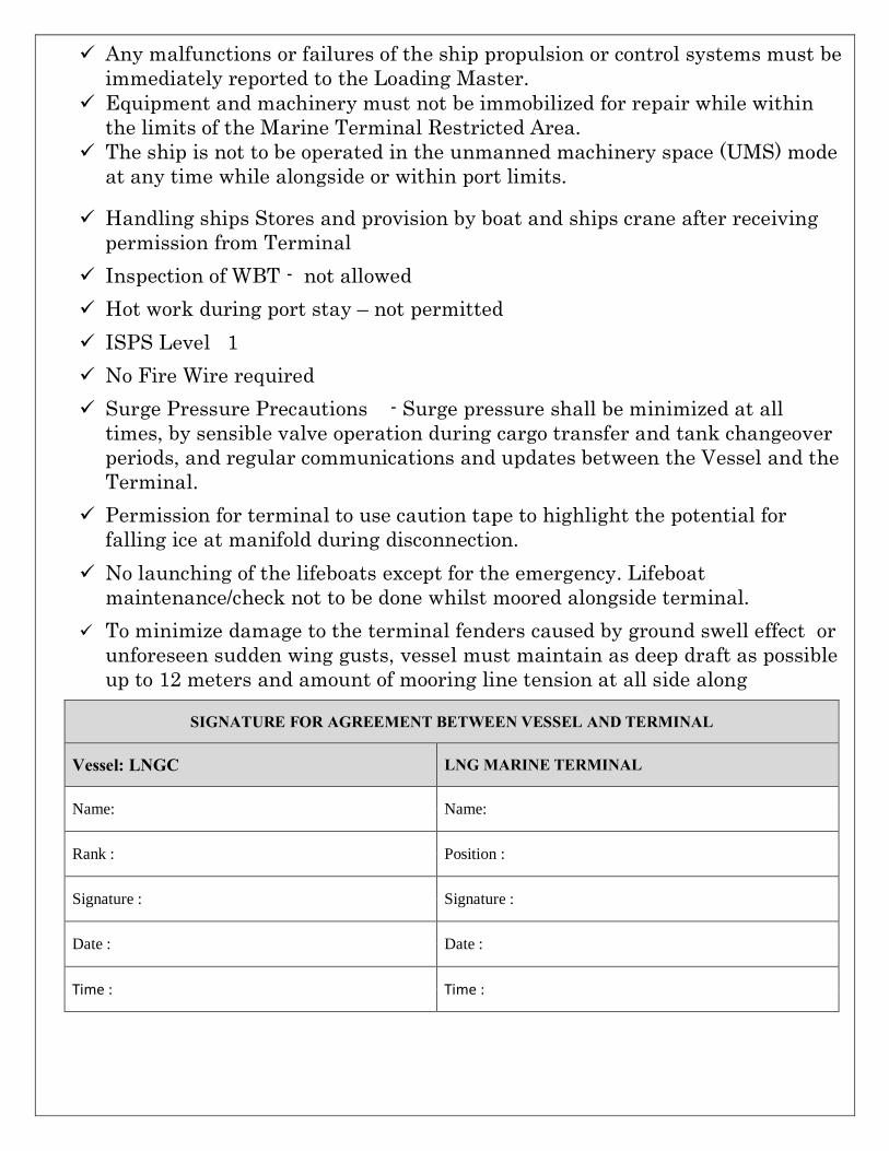
ü Any malfunctions or failures of the ship propulsion or control systems must be immediately reported to the Loading Master.
ü Equipment and machinery must not be immobilized for repair while within the limits of the Marine Terminal Restricted Area.
ü The ship is not to be operated in the unmanned machinery space (UMS) mode at any time while alongside or within port limits.
ü Handling ships Stores and provision by boat and ships crane after receiving permission from Terminal
ü Inspection of WBT - not allowed ü Hot work during port stay – not permitted ü ISPS Level 1 ü No Fire Wire required ü Surge Pressure Precautions - Surge pressure shall be minimized at all
times, by sensible valve operation during cargo transfer and tank changeover periods, and regular communications and updates between the Vessel and the Terminal.
ü Permission for terminal to use caution tape to highlight the potential for falling ice at manifold during disconnection.
ü No launching of the lifeboats except for the emergency. Lifeboat maintenance/check not to be done whilst moored alongside terminal.
ü To minimize damage to the terminal fenders caused by ground swell effect or unforeseen sudden wing gusts, vessel must maintain as deep draft as possible up to 12 meters and amount of mooring line tension at all side along
SIGNATURE FOR AGREEMENT BETWEEN VESSEL AND TERMINAL
Vessel: LNGC LNG MARINE TERMINAL
Name: Name:
Rank : Position :
Signature : Signature :
Date : Date :
Time : Time :
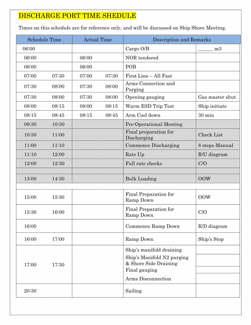
DISCHARGE PORT TIME SHEDULE Times on this schedule are for reference only, and will be discussed on Ship Shore Meeting.
Schedule Time Actual Time Description and Remarks 06:00 Cargo O/B ______ m3
06:00 06:00 NOR tendered 06:00 06:00 POB 07:00 07:30 07:00 07:30 First Line – All Fast
07:30 08:00 07:30 08:00 Arms Connection and Purging
07:30 08:00 07:30 08:00 Opening gauging Gas master shut 08:00 08:15 08:00 08:15 Warm ESD Trip Test Ship initiate 08:15 08:45 08:15 08:45 Arm Cool down 30 min 09:30 10:30 Pre-Operational Meeting
10:30 11:00 Final preparation for Discharging Check List
11:00 11:10 Commence Discharging 8 steps Manual 11:10 12:00 Rate Up R/U diagram 12:00 12:30 Full rate checks C/O
13:00 14:30 Bulk Loading OOW
15:00 15:30 Final Preparation for Ramp Down OOW
15:30 16:00 Final Preparation for Ramp Down C/O
16:00 Commence Ramp Down R/D diagram
16:00 17:00 Ramp Down Ship’s Stop
17:00 17:30
Ship’s manifold draining Ship’s Manifold N2 purging & Shore Side Draining
Final gauging Arms Disconnection
20:30 Sailing