Embed Size (px)
Citation preview
®
Load Banks andLoad Testing Accessories
by
Simplex Onsite, Inc.SOS Rentals
SOS Technical Services
Simplex Onsite, Inc.Springfi eld, Illinois (Home Offi ce)Atlanta • Houston • Cleveland • Minneapolis
217-483-1600Fax 217-483-1616www.simplexdirect.com
© 2012 Simplex Onsite, Inc. All rights reserved.Printed in the USA • 1106-01.01Design subject to change without notice.
Load Bank Testing of Electrical Power SourcesAny device which generates electricity may require testing. This can be for product development, production line testing, product demonstration, commissioning of a new installation or for periodic service, maintenance or trouble shooting. Although the most common use of load banks for testing is with engine generator sets, in fact, any device which generates electricity may require a load bank for testing, service or calibration. This includes UPS, batteries, power supplies, fuel cells, solar cells, wind turbines, hydro generators, etc. A load bank provides a stable, known, controllable and relatively “harmless” load for these purposes. That is, if the performance of the generator is not known, it is better to evaluate the performance with a load bank than with critical facility loads.
Load Bank OverviewLoad banks simulate the “real world” loads that the power source will experience. Electrical load can be broadly classifi ed as resistive, magnetic and capacitive. In the real world, these components are mixed, as they are with a load bank, except with the load bank, full control of the components is possible. Resistive loads comprise incandescent lighting, electric heating and other loads in which electrical energy is largely converted to heat. Magnetic loads comprise motors, transformers and other devices which convert electrical energy to mechanical force. Capacitive loads comprise electronic loads. Although both AC and DC systems power similar loads, most of this discussion will involve AC systems. The most common load bank and the load bank which is suitable for general load testing is the resistive load bank. A resistive load bank converts electrical energy to heat. Within the load bank, the load is divided into discrete circuits or “steps” capable of stepwise, controlled application. The load bank includes a means of cooling, most commonly forced air, but also water. The load bank also includes protective sensors, circuit protection devices, instrumentation, an operator interface and a means of connection to the generator. To simulate magnetic or motor loads, an inductive load bank is added to the resistive load bank. This can take the form of an integrated, all-in-one package, or separate units. Likewise, a capacitive load bank can be added. Inductive and capacitive load banks are always used in conjunction with a resistive load bank-- there is generally no reason to use one alone. Inductive and capacitive load banks, also known collectively as “reactive” load banks, are only used on AC systems and result in lagging or leading power factor for inductive or capacitive loads respectively.
Load Test CapacityThe desired capacity of the load test is expressed in kilowatts (KW). KW corresponds directly to engine HP (.746 HP = KW) and is developed exclusively by the resistive load bank. Adding reactive load changes the total KVA of the load, but does not alter the KW or HP load. A purely resistive load bank provides a realistic and effective test of the prime mover and causes full load currents to be developed by the generator. The engine will develop full rated HP, operating pressures and temperatures, and the performance of the governor will be fully evaluated. Adding inductive load allows for the full KVA capacity of the generator to be developed for a full functional test of temperature rise, waveform quality, voltage regulator response and reactive load sharing.
VoltageLow voltage AC systems are rated 120/240v, single-phase, 2 or 3 wire; 208-240/416-480/575-600vAC, 3 or 4 wire. Medium voltage systems are in the 5kV or 15kV class. DC systems can range from battery voltages of 12/24/32v, 125/250v, or 350/700v, typically. Keep in mind that the AC load banks in this catalog are generally 3-phase, 3-wire loads, meaning that a neutral is not required and that loads are applied in 3-phase balanced steps
CurrentCurrent, expressed in amperes, is found by the following formula:
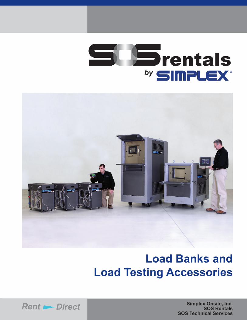
Low Power Factor TestingBy adding an inductive load to the resistive load, lagging power factor can be obtained. Commercial loads, as well as generator sets, are rated at the nominal power factor of 0.8 lagging. This number is the cosine of the angle made between the KW and the KVA in the diagram below:
Fundamentals of Load Bank Rentals • Page 2
3ph. A =KW x 1000
( V x 1.73 x P.F. )
COS = Power Factor
kVA
kVAR
kW
PF =KW
KVA
TAN x KW = KVAR
KVA = KW + KVAR2 2
Current must be known in order to size connection cables. Keep in mind that connection cables have a certain small resistance, and that a small voltage drop will be seen across the cable set and at the terminals of the load bank. Therefore, although the generator instrumentation may indicate 480v, the load bank instrumentation will measure the terminal voltage at the load bank, for example, 473v.
KW as a Function of VoltageKW varies as the square of the voltage: therefore, in the preceding example, if the load bank terminal voltage is reduced to 473v, then the resultant KW will be 97% of the rated KW. Where did that power go? It is lost as heat in the connection cables.
The magnitude of inductive load required to obtain 0.8 power factor is 0.75 X the KW (1000kw + 750kvar = 1250kva at 0.8 lagging power factor). As a point of interest, 0.75 is the tangent of the aforementioned angle. Keep in mind when sizing cables that the full load current at the rated KVA must be calculated.
Leading Power Factor TestingThe same rationale as above applies to leading power factor, except capacitive load is added. Leading power factor testing is rare and specialized. Most engine generator sets cannot tolerate more than a very small degree of leading power factor.
Portability and Site ConditionsWhen designing a load bank rental, considerations must be given to site space, access and set up. All SOS Rental Load Banks listed herein can be networked in groups and connected in parallel to provide a total, aggregate load. It may be more workable to network 10 SOS Powerstar Load Banks to obtain 1000kw than rent a single Atlas Load Bank.
Networking and ParallelingAll SOS Rental Load Banks can be networked and paralleled to form larger systems. Powerstar Load Banks can only be networked with other Powerstar Load Banks. All other models can be networked and paralleled in any mix and match combination up to a maximum number of units. All control is centralized in a single operator interface. All data is likewise totalized to the operator interface. Networking is via data cables provided with the load banks. Power cables are paralleled to the power source.Continued on page 12.
© 2012 Simplex Onsite, Inc. All rights reserved.Printed in the USA • 1106-01.01
Design subject to change without notice.
217-483-1600Fax 217-483-1616
www.simplexdirect.com
Simplex Onsite, Inc.Springfi eld, Illinois (Home Offi ce)
Atlanta • Houston • Cleveland • Minneapolis
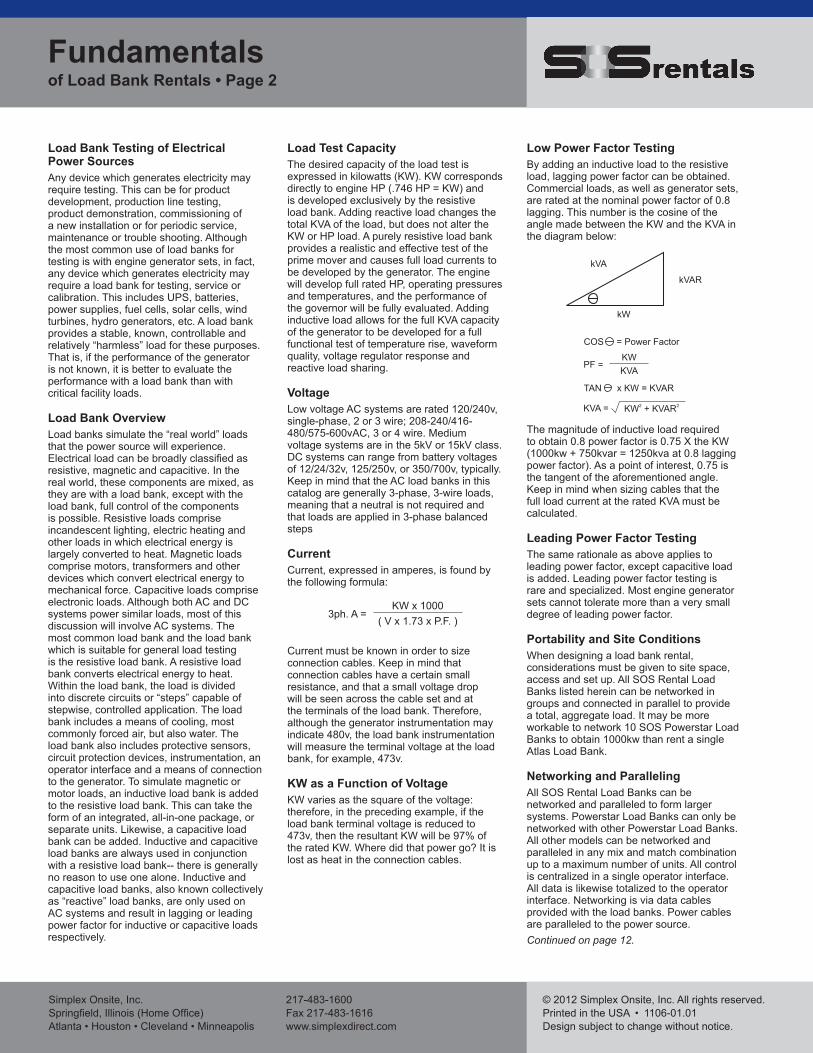
Rental Load Bank Considerations 5. Control requirements: local/remote,
manual/automatic6. Data acquisition requirements7. Connection cable requirements8. Technician/operator requirements9. Other accessories needed
All SOS Rental Load Banks are portable units suitable for fi eld use. Rental load banks are differentiated by capacity, voltage and frequency rating, and relative portability.
All SOS Rental Load Banks are digitally controlled and network capable. Powerstar Load Banks can be networked in systems of up to 40 units, but cannot be networked to other models. All other SOS Load Banks can be networked in any combination and in any mix of models, up to a practical limit of 20 units. All SOS Rental Load Banks, except Powerstar, have data acquisition capability. Powerstar requires accessory data acquisition package.
1. Capacity required for the test: KW, power factor, Voltage
2. Rental Load Bank System Architecture: one unit or multiple networked units
3. Site conditions for the test: indoor/outdoor, ventilation and access limitations, environmental conditions
4. Duration of test, if system is to remain set-up for long periods
Load Bank Rental Selection Guide • Page 3
Electra - 700KW
dynaMITE - 400KW
PowerStar - 100KWAtlas - 1000KW
Magnex - 300-938KVAR
Load Ranger - 1500-3000KW, 1125-2250KVAR
Load Cube - 2500KW, 0.8 p.f.
Trident - 1250-2500KW
Simplex Onsite, Inc.Springfi eld, Illinois (Home Offi ce)Atlanta • Houston • Cleveland • Minneapolis
217-483-1600Fax 217-483-1616www.simplexdirect.com
© 2012 Simplex Onsite, Inc. All rights reserved.Printed in the USA • 1106-01.01Design subject to change without notice.
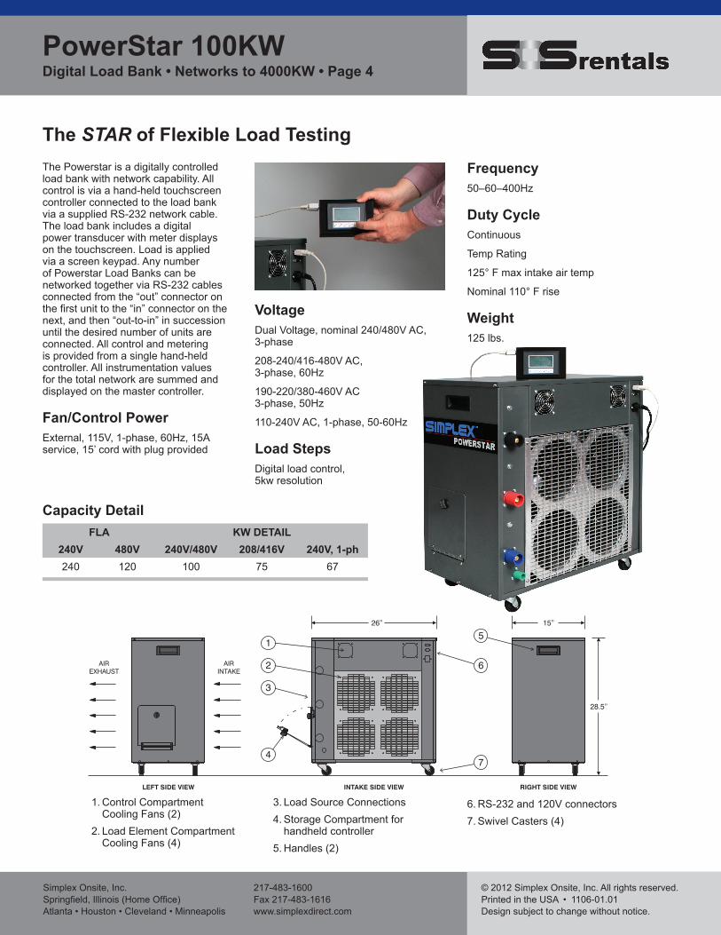
The STAR of Flexible Load Testing
VoltageDual Voltage, nominal 240/480V AC, 3-phase
208-240/416-480V AC,3-phase, 60Hz
190-220/380-460V AC3-phase, 50Hz
110-240V AC, 1-phase, 50-60Hz
Load StepsDigital load control,5kw resolution
The Powerstar is a digitally controlled load bank with network capability. All control is via a hand-held touchscreen controller connected to the load bank via a supplied RS-232 network cable. The load bank includes a digital power transducer with meter displays on the touchscreen. Load is applied via a screen keypad. Any number of Powerstar Load Banks can be networked together via RS-232 cables connected from the “out” connector on the fi rst unit to the “in” connector on the next, and then “out-to-in” in succession until the desired number of units are connected. All control and metering is provided from a single hand-held controller. All instrumentation values for the total network are summed and displayed on the master controller.
Fan/Control PowerExternal, 115V, 1-phase, 60Hz, 15A service, 15’ cord with plug provided
Frequency50–60–400Hz
Duty CycleContinuous
Temp Rating
125° F max intake air temp
Nominal 110° F rise
Weight125 lbs.
1. Control Compartment Cooling Fans (2)2. Load Element Compartment
Cooling Fans (4)
3. Load Source Connections4. Storage Compartment for handheld controller5. Handles (2)
6. RS-232 and 120V connectors7. Swivel Casters (4)
FLA KW DETAIL240V 480V 240V/480V 208/416V 240V, 1-ph240 120 100 75 67
Capacity Detail
PowerStar 100KW Digital Load Bank • Networks to 4000KW • Page 4
© 2012 Simplex Onsite, Inc. All rights reserved.Printed in the USA • 1106-01.01
Design subject to change without notice.
217-483-1600Fax 217-483-1616
www.simplexdirect.com
Simplex Onsite, Inc.Springfi eld, Illinois (Home Offi ce)
Atlanta • Houston • Cleveland • Minneapolis
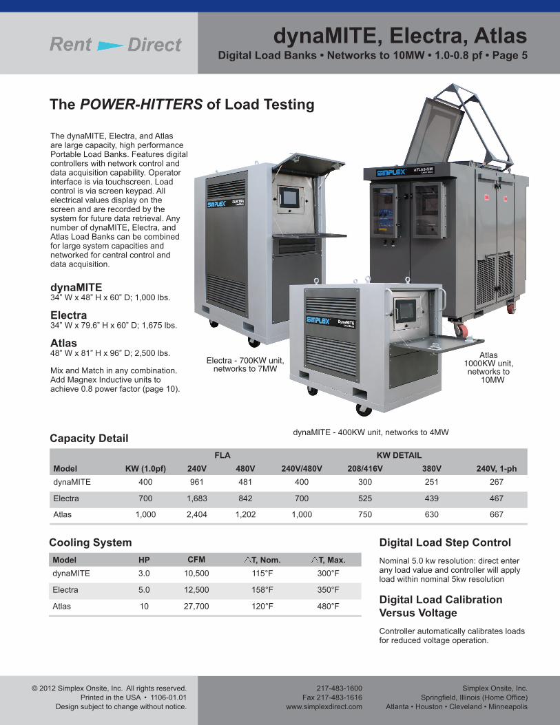
The POWER-HITTERS of Load Testing
The dynaMITE, Electra, and Atlas are large capacity, high performance Portable Load Banks. Features digital controllers with network control and data acquisition capability. Operator interface is via touchscreen. Load control is via screen keypad. All electrical values display on the screen and are recorded by the system for future data retrieval. Any number of dynaMITE, Electra, and Atlas Load Banks can be combined for large system capacities and networked for central control and data acquisition.
dynaMITE34” W x 48” H x 60” D; 1,000 lbs.
Electra34” W x 79.6” H x 60” D; 1,675 lbs.
Atlas48” W x 81” H x 96” D; 2,500 lbs.
Mix and Match in any combination. Add Magnex Inductive units to achieve 0.8 power factor (page 10).
Model KW (1.0pf)FLA KW DETAIL
240V 480V 240V/480V 208/416V 380V 240V, 1-phdynaMITE 400 961 481 400 300 251 267
Electra 700 1,683 842 700 525 439 467
Atlas 1,000 2,404 1,202 1,000 750 630 667
Capacity Detail
Model HP CFM T, Nom. T, Max.dynaMITE 3.0 10,500 115°F 300°F
Electra 5.0 12,500 158°F 350°F
Atlas 10 27,700 120°F 480°F
Cooling System Digital Load Step ControlNominal 5.0 kw resolution: direct enter any load value and controller will apply load within nominal 5kw resolution
Digital Load Calibration Versus VoltageController automatically calibrates loads for reduced voltage operation.
dynaMITE - 400KW unit, networks to 4MW
Electra - 700KW unit,networks to 7MW
Atlas1000KW unit,networks to
10MW
dynaMITE, Electra, AtlasDigital Load Banks • Networks to 10MW • 1.0-0.8 pf • Page 5
Simplex Onsite, Inc.Springfi eld, Illinois (Home Offi ce)Atlanta • Houston • Cleveland • Minneapolis
217-483-1600Fax 217-483-1616www.simplexdirect.com
© 2012 Simplex Onsite, Inc. All rights reserved.Printed in the USA • 1106-01.01Design subject to change without notice.
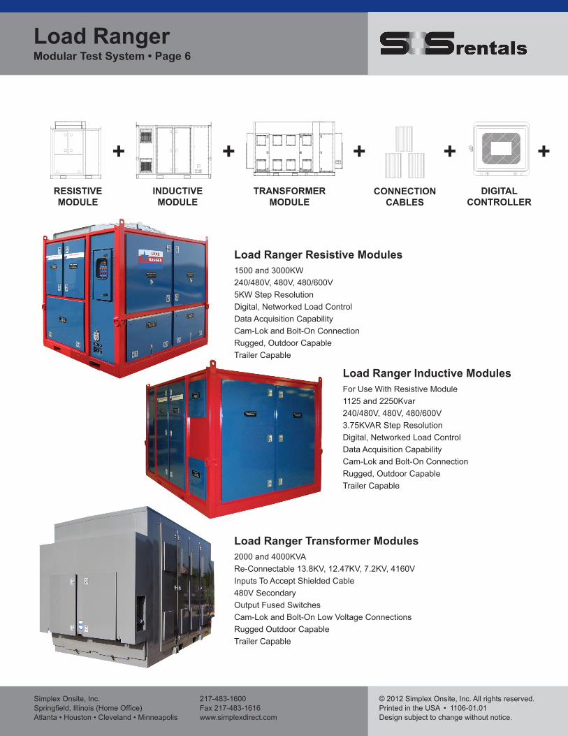
Load Ranger Inductive ModulesFor Use With Resistive Module1125 and 2250Kvar240/480V, 480V, 480/600V3.75KVAR Step ResolutionDigital, Networked Load ControlData Acquisition CapabilityCam-Lok and Bolt-On ConnectionRugged, Outdoor CapableTrailer Capable
Load Ranger Transformer Modules2000 and 4000KVARe-Connectable 13.8KV, 12.47KV, 7.2KV, 4160VInputs To Accept Shielded Cable480V SecondaryOutput Fused SwitchesCam-Lok and Bolt-On Low Voltage ConnectionsRugged Outdoor CapableTrailer Capable
Load Ranger Resistive Modules1500 and 3000KW 240/480V, 480V, 480/600V5KW Step ResolutionDigital, Networked Load ControlData Acquisition CapabilityCam-Lok and Bolt-On ConnectionRugged, Outdoor CapableTrailer Capable
RESISTIVEMODULE
+ +INDUCTIVEMODULE
TRANSFORMERMODULE
+CONNECTION
CABLESDIGITAL
CONTROLLER
+ +
Load Ranger Modular Test System • Page 6
© 2012 Simplex Onsite, Inc. All rights reserved.Printed in the USA • 1106-01.01
Design subject to change without notice.
217-483-1600Fax 217-483-1616
www.simplexdirect.com
Simplex Onsite, Inc.Springfi eld, Illinois (Home Offi ce)
Atlanta • Houston • Cleveland • Minneapolis
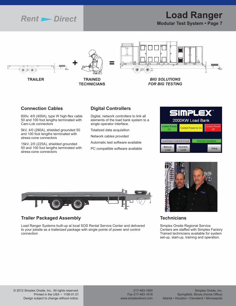
Connection Cables600v, 4/0 (400A), type W high-fl ex cable 50 and 100 foot lengths terminated with Cam-Lok connectors
5kV, 4/0 (280A), shielded grounded 50 and 100 foot lengths terminated with stress-cone connectors
15kV, 2/0 (225A), shielded grounded 50 and 100 foot lengths terminated with stress-cone connectors
Trailer Packaged AssemblyLoad Ranger Systems built-up at local SOS Rental Service Center and delivered to your jobsite as a trailerized package with single points of power and control connection
TechniciansSimplex Onsite Regional Service Centers are staffed with Simplex Factory Trained technicians available for system set-up, start-up, training and operation.
Digital ControllersDigital, network controllers to link all elements of the load bank system to a single operator interface.
Totalized data acquisition
Network cables provided
Automatic test software available
PC compatible software available
TRAINEDTECHNICIANS
=TRAILER
+BIG SOLUTIONS
FOR BIG TESTING
Load RangerModular Test System • Page 7
Simplex Onsite, Inc.Springfi eld, Illinois (Home Offi ce)Atlanta • Houston • Cleveland • Minneapolis
217-483-1600Fax 217-483-1616www.simplexdirect.com
© 2012 Simplex Onsite, Inc. All rights reserved.Printed in the USA • 1106-01.01Design subject to change without notice.
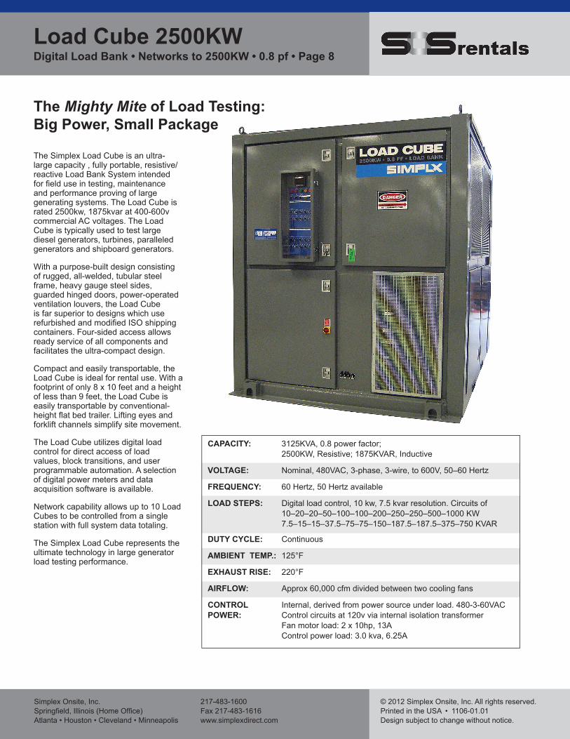
The Mighty Mite of Load Testing: Big Power, Small Package
The Simplex Load Cube is an ultra-large capacity , fully portable, resistive/reactive Load Bank System intended for fi eld use in testing, maintenance and performance proving of large generating systems. The Load Cube is rated 2500kw, 1875kvar at 400-600v commercial AC voltages. The Load Cube is typically used to test large diesel generators, turbines, paralleled generators and shipboard generators.
With a purpose-built design consisting of rugged, all-welded, tubular steel frame, heavy gauge steel sides, guarded hinged doors, power-operated ventilation louvers, the Load Cube is far superior to designs which use refurbished and modifi ed ISO shipping containers. Four-sided access allows ready service of all components and facilitates the ultra-compact design.
Compact and easily transportable, the Load Cube is ideal for rental use. With a footprint of only 8 x 10 feet and a height of less than 9 feet, the Load Cube is easily transportable by conventional-height fl at bed trailer. Lifting eyes and forklift channels simplify site movement.
The Load Cube utilizes digital load control for direct access of load values, block transitions, and user programmable automation. A selection of digital power meters and data acquisition software is available.
Network capability allows up to 10 Load Cubes to be controlled from a single station with full system data totaling.
The Simplex Load Cube represents the ultimate technology in large generator load testing performance.
CAPACITY: 3125KVA, 0.8 power factor; 2500KW, Resistive; 1875KVAR, Inductive
VOLTAGE: Nominal, 480VAC, 3-phase, 3-wire, to 600V, 50–60 Hertz
FREQUENCY: 60 Hertz, 50 Hertz available
LOAD STEPS: Digital load control, 10 kw, 7.5 kvar resolution. Circuits of 10–20–20–50–100–100–200–250–250–500–1000 KW 7.5–15–15–37.5–75–75–150–187.5–187.5–375–750 KVAR
DUTY CYCLE: Continuous
AMBIENT TEMP.: 125°F
EXHAUST RISE: 220°F
AIRFLOW: Approx 60,000 cfm divided between two cooling fans
CONTROL Internal, derived from power source under load. 480-3-60VACPOWER: Control circuits at 120v via internal isolation transformer Fan motor load: 2 x 10hp, 13A Control power load: 3.0 kva, 6.25A
Load Cube 2500KWDigital Load Bank • Networks to 2500KW • 0.8 pf • Page 8
© 2012 Simplex Onsite, Inc. All rights reserved.Printed in the USA • 1106-01.01
Design subject to change without notice.
217-483-1600Fax 217-483-1616
www.simplexdirect.com
Simplex Onsite, Inc.Springfi eld, Illinois (Home Offi ce)
Atlanta • Houston • Cleveland • Minneapolis
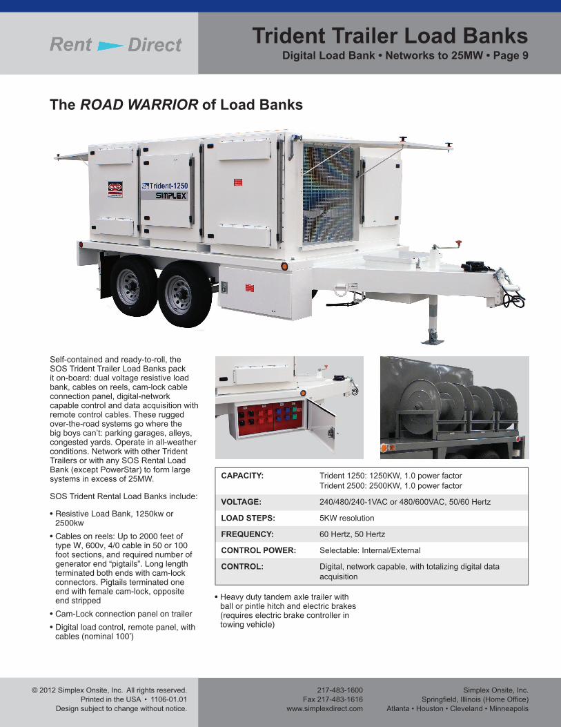
The ROAD WARRIOR of Load Banks
CAPACITY: Trident 1250: 1250KW, 1.0 power factor Trident 2500: 2500KW, 1.0 power factor
VOLTAGE: 240/480/240-1VAC or 480/600VAC, 50/60 Hertz
LOAD STEPS: 5KW resolution
FREQUENCY: 60 Hertz, 50 Hertz
CONTROL POWER: Selectable: Internal/External
CONTROL: Digital, network capable, with totalizing digital data acquisition
Self-contained and ready-to-roll, the SOS Trident Trailer Load Banks pack it on-board: dual voltage resistive load bank, cables on reels, cam-lock cable connection panel, digital-network capable control and data acquisition with remote control cables. These rugged over-the-road systems go where the big boys can’t: parking garages, alleys, congested yards. Operate in all-weather conditions. Network with other Trident Trailers or with any SOS Rental Load Bank (except PowerStar) to form large systems in excess of 25MW.
SOS Trident Rental Load Banks include:
• Resistive Load Bank, 1250kw or 2500kw
• Cables on reels: Up to 2000 feet of type W, 600v, 4/0 cable in 50 or 100 foot sections, and required number of generator end “pigtails”. Long length terminated both ends with cam-lock connectors. Pigtails terminated one end with female cam-lock, opposite end stripped
• Cam-Lock connection panel on trailer
• Digital load control, remote panel, with cables (nominal 100’)
• Heavy duty tandem axle trailer with ball or pintle hitch and electric brakes (requires electric brake controller in towing vehicle)
Trident Trailer Load BanksDigital Load Bank • Networks to 25MW • Page 9
Simplex Onsite, Inc.Springfi eld, Illinois (Home Offi ce)Atlanta • Houston • Cleveland • Minneapolis
217-483-1600Fax 217-483-1616www.simplexdirect.com
© 2012 Simplex Onsite, Inc. All rights reserved.Printed in the USA • 1106-01.01Design subject to change without notice.
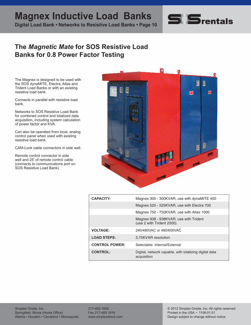
The Magnetic Mate for SOS Resistive Load Banks for 0.8 Power Factor Testing
The Magnex is designed to be used with the SOS dynaMITE, Electra, Atlas and Trident Load Banks or with an existing resistive load bank.
Connects in parallel with resistive load bank.
Networks to SOS Resistive Load Bank for combined control and totalized data acquisition, including system calculation of power factor and KVA.
Can also be operated from local, analog control panel when used with existing resistive load bank.
CAM-Lock cable connectors in side well.
Remote control connector in side well and 25’ of remote control cable (connects to communications port on SOS Resistive Load Bank).
CAPACITY: Magnex 300 - 300KVAR, use with dynaMITE 400
Magnex 525 - 525KVAR, use with Electra 700
Magnex 750 - 750KVAR, use with Atlas 1000
Magnex 938 - 938KVAR, use with Trident (use 2 with Trident 2500)
VOLTAGE: 240/480VAC or 480/600VAC
LOAD STEPS: 3.75KVAR resolution
CONTROL POWER: Selectable: Internal/External
CONTROL: Digital, network capable, with totalizing digital data acquisition
Magnex Inductive Load Banks Digital Load Bank • Networks to Resistive Load Banks • Page 10
© 2012 Simplex Onsite, Inc. All rights reserved.Printed in the USA • 1106-01.01
Design subject to change without notice.
217-483-1600Fax 217-483-1616
www.simplexdirect.com
Simplex Onsite, Inc.Springfi eld, Illinois (Home Offi ce)
Atlanta • Houston • Cleveland • Minneapolis
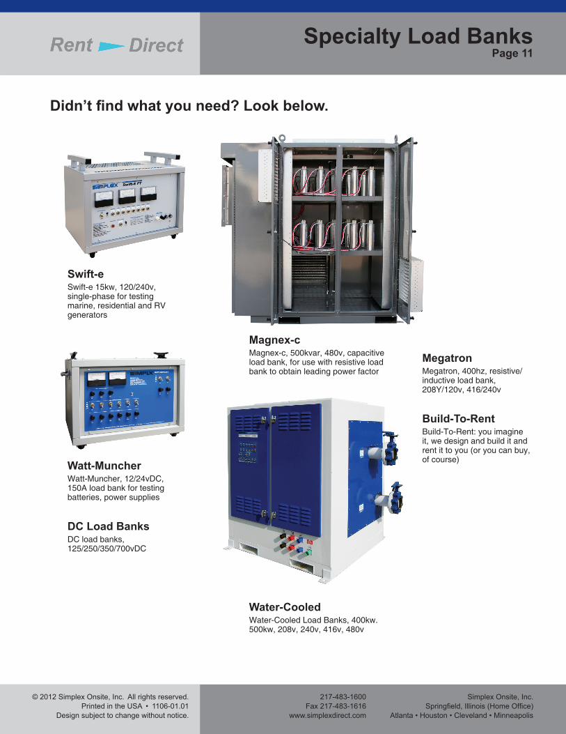
Didn’t fi nd what you need? Look below.
Swift-eSwift-e 15kw, 120/240v, single-phase for testing marine, residential and RV generators
Specialty Load BanksPage 11
Watt-MuncherWatt-Muncher, 12/24vDC, 150A load bank for testing batteries, power supplies
DC Load BanksDC load banks, 125/250/350/700vDC
Magnex-cMagnex-c, 500kvar, 480v, capacitive load bank, for use with resistive load bank to obtain leading power factor
Water-CooledWater-Cooled Load Banks, 400kw. 500kw, 208v, 240v, 416v, 480v
MegatronMegatron, 400hz, resistive/inductive load bank, 208Y/120v, 416/240v
Build-To-RentBuild-To-Rent: you imagine it, we design and build it and rent it to you (or you can buy, of course)
Simplex Onsite, Inc.Springfi eld, Illinois (Home Offi ce)Atlanta • Houston • Cleveland • Minneapolis
217-483-1600Fax 217-483-1616www.simplexdirect.com
© 2012 Simplex Onsite, Inc. All rights reserved.Printed in the USA • 1106-01.01Design subject to change without notice.
Rental AccessoriesPage 12
Sizing and Running CablesRental cables listed in this catalog should be operated at approximately 85% maximum of their open air current rating. Ampere ratings listed are the NEC free air ratings. Cables listed are suitable for wet or dry aboveground use and should be run in a well ventilated area. Keep cable splice points out of water. 3-phase cables must be of absolutely equal length, especially when multiple cables are run per phase. Run 3-phase cables in 3-phase groupings, ideally arrayed in a triangle, but at least side-by-side. Never separate phases into A-B-C clusters as this can lead to electromagnetically induced current imbalances, voltage drops and cable overheating.
Ground CablesRun at least 33% ground capacity. Connect ground cables to ground terminals or ground bar in the load bank. Connect the other end to the generator ground. Be sure that the generator is solidly grounded to earth ground. Avoid multiple earth grounds as this can lead to potential differences among the ground points with resultant circulating ground currents.
Heat and Airfl owThe user needs to appreciate how hot a load bank gets and how much hot air is produced. As a guide, temp rise (F) = KW x 3000/CFM. Load banks are heat producing devices and must be ventilated. Observe the CFM capacity of the load bank and be certain that equivalent air intake is provided. If operated indoors, be cautious to prevent recirculation of exhaust air and observe ambient temperatures. Do not operate vertical airfl ow load banks under a close ceiling. Maintain a max ambient of no more than 125°F. Load banks greater than 100kw (Powerstar 100) are ideally operated outdoors and extreme caution should be exercised in the 100-700kw range. Above 700kw, an indoor space would have to be voluminous and well ventilated. Indoors, note the presence of sprinkler heads as the load bank WILL ACTIVATE sprinklers very quickly. Outdoors, be observant of adjacent equipment, buildings, plantings. Operate in an area with clear sky above. Avoid putting the load bank in a virtual pit by surrounding it with tall walls or buildings. Space multiple load banks 4-6 feet apart, greater with larger units.
SafetyLoad banks are not inherently dangerous but there are dangers that exist with operation of load banks. This is a technical, industrial product and should only be set-up and operated by trained, technical personnel who are specifi cally authorized by the renter. Be certain that all equipment is properly grounded. Carefully check cables for wear and tear, insulation damage. Check all cam-lock connectors that connections are made sound and tight including both connector mating (the connector twist-tightens) and the cable within the connector. Be certain that cables are phased correctly. A circuit breaker or fuse set is required at the power source sized appropriately for the conductor run. Be sure to run adequate ampacity of cables. Check that generator voltage corresponds to load bank voltage. Check correct airfl ow direction and if it is necessary to reverse cooling fan direction, allow fan to fully stop before reversing. Provide the CFM required at an ambient not to exceed 125°F. Be observant of airfl ow restrictions and recirculation of airfl ow. Be careful that foreign objects are not drawn into cooling intakes. Do not operate indoor load banks in the rain. Observe common and accepted practices when operated high voltage electrical equipment. Note that load bank exterior, exhaust screens and other sheet metal parts can be very hot. Wear hearing protection as required.
Fundamentals of Load Bank Rentals cont’d from page 2
Rental Connection Cables600v, 4/0 (400A), type W high-fl ex cable50 and 100 foot lengthsTerminated with Cam-Lok connectors
5kV, 4/0 (280A), shielded grounded50 and 100 foot lengthsTerminated with stress-cone connectors
15kV, 2/0 (225A), shielded grounded50 and 100 foot lengthsTerminated with stress-cone connectors
Supplied as bulk cable or on reels
Digital Controllers and Data AcquisitionData acquisition package for Powerstar load bank system
Automatic test software
PC compatible test software
Trailer PackagingSystems built-up at local SOS Rental Service Center and delivered to your jobsite as a trailerized package with single points of power and control connection
TechniciansSimplex Onsite Regional Service Centers are staffed with Simplex Factory Trained technicians available for system set-up, start-up, training and operation.
Delivery and PickupYour load bank rental system delivered to your jobsite and picked up by SOS.