Embed Size (px)
Citation preview

Load Testing of Precast Concrete Plank By Peter Gorgas, E.I.T.
Figure A. Maximum load testing of new precast concrete floor plank system Overview Testing was performed in July 2012 at Northeast Precast LLC in Millville, N.J., to analyze the performance of a floor plank system under loading. The purpose of the test was to show that this system can handle above and beyond the typical design loads we work with, while offering advantages over other systems – advantages such as lighter weight and insulation, as Dr. Mahgoub’s article brings out.
Figure A shows maximum loading of the test plank and the midspan deflection with the weights stacked to the upper limit than could be reached safely with the test setup. Shown in Figure B, the plank is similar in design to a double-tee, but is very shallow and has four stems instead of two. It uses prestressed strands in the stems and mild reinforcing in the 11/8-in. thick flange.
Figure B – 8-ft wide prestressed plank
A typical piece is 8 ft wide. The last 2 in. on each end are solid concrete for a continuous bearing surface. For the purposes of this test, a smaller representative section was chosen. Two planks (with a length of 26 ft, 1 in.) were cast, with the cross section shown in Figure C.
Figure C – Section of test plank The planks were cast July 5, 2012, and had reached a compressive strength of 7,000 psi after two weeks (when the planks were initially loaded), and a compressive strength of 7,600 psi after three weeks (when the planks were loaded to failure). Each stem had a ½-in.-diameter strand stressed to 31 kips. The flange reinforcing consisted of 2-ft-long No. 3 bars at 18-in. O.C. For the test, two planks were placed side by side and a 2 in. topping was poured over them, so that the actual plank tested had the section shown in Figure D. The topping was 2 in. thick at the center of the plank, and thicker toward the ends due to the plank’s camber.
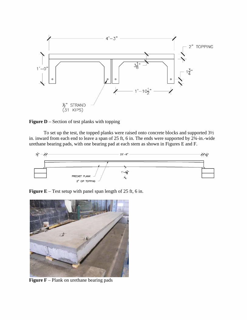
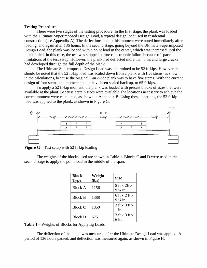
Figure D – Section of test planks with topping To set up the test, the topped planks were raised onto concrete blocks and supported 3½ in. inward from each end to leave a span of 25 ft, 6 in. The ends were supported by 2¾-in.-wide urethane bearing pads, with one bearing pad at each stem as shown in Figures E and F.
Figure E – Test setup with panel span length of 25 ft, 6 in.
Figure F – Plank on urethane bearing pads
Testing Procedure There were two stages of the testing procedure. In the first stage, the plank was loaded with the Ultimate Superimposed Design Load, a typical design load used in residential construction (see Appendix A). The deflections due to this moment were noted immediately after loading, and again after 136 hours. In the second stage, going beyond the Ultimate Superimposed Design Load, the plank was loaded with a point load in the center, which was increased until the plank failed. In this case, the test was stopped before catastrophic failure because of space limitations of the test setup. However, the plank had deflected more than 8 in. and large cracks had developed through the full depth of the plank. The Ultimate Superimposed Design Load was determined to be 52 ft-kips. However, it should be noted that the 52 ft-kip load was scaled down from a plank with five stems, as shown in the calculations, because the original 8-in.-wide plank was to have five stems. With the current design of four stems, the moment should have been scaled back up, to 65 ft-kips. To apply a 52 ft-kip moment, the plank was loaded with precast blocks of sizes that were available at the plant. Because certain sizes were available, the locations necessary to achieve the correct moment were calculated, as shown in Appendix B. Using these locations, the 52 ft-kip load was applied to the plank, as shown in Figure G.
Figure G – Test setup with 52 ft-kip loading The weights of the blocks used are shown in Table 1. Blocks C and D were used in the second stage to apply the point load in the middle of the span.
Block Type
Weight (lbs) Size
Block A 1156 5 ft × 2ft × 9 ¼ in.
Block B 1388 6 ft × 2 ft × 9 ¼ in.
Block C 1350 3 ft × 3 ft × 1 in.
Block D 675 3 ft × 3 ft × 6 in.
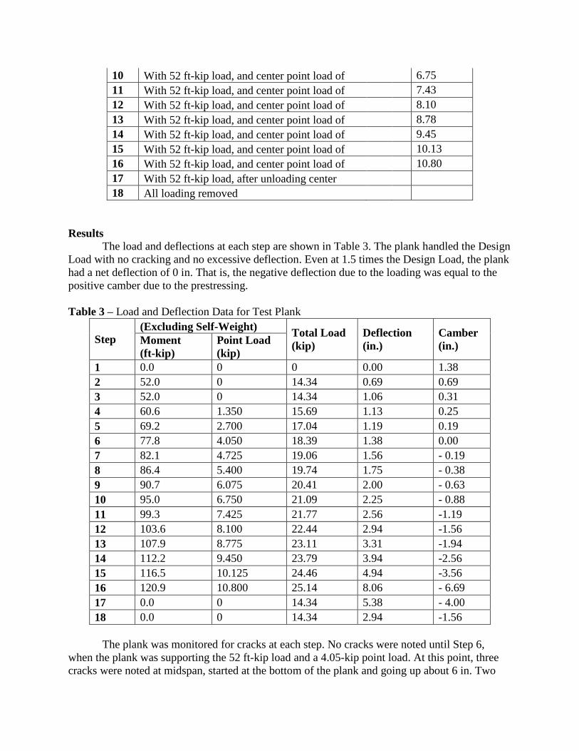
Table 1 – Weights of Blocks for Applying Loads The deflection of the plank was measured after the Ultimate Design Load was applied. A period of 136 hours passed, and deflection was measured again, as shown in Figure H.
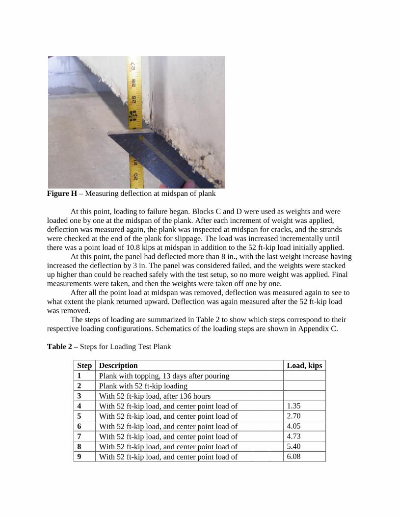
Figure H – Measuring deflection at midspan of plank At this point, loading to failure began. Blocks C and D were used as weights and were loaded one by one at the midspan of the plank. After each increment of weight was applied, deflection was measured again, the plank was inspected at midspan for cracks, and the strands were checked at the end of the plank for slippage. The load was increased incrementally until there was a point load of 10.8 kips at midspan in addition to the 52 ft-kip load initially applied. At this point, the panel had deflected more than 8 in., with the last weight increase having increased the deflection by 3 in. The panel was considered failed, and the weights were stacked up higher than could be reached safely with the test setup, so no more weight was applied. Final measurements were taken, and then the weights were taken off one by one. After all the point load at midspan was removed, deflection was measured again to see to what extent the plank returned upward. Deflection was again measured after the 52 ft-kip load was removed. The steps of loading are summarized in Table 2 to show which steps correspond to their respective loading configurations. Schematics of the loading steps are shown in Appendix C. Table 2 – Steps for Loading Test Plank
Step Description Load, kips 1 Plank with topping, 13 days after pouring 2 Plank with 52 ft-kip loading 3 With 52 ft-kip load, after 136 hours 4 With 52 ft-kip load, and center point load of
1.35
5 With 52 ft-kip load, and center point load of
2.70 6 With 52 ft-kip load, and center point load of
4.05
7 With 52 ft-kip load, and center point load of
4.73 8 With 52 ft-kip load, and center point load of
5.40
9 With 52 ft-kip load, and center point load of
6.08
10 With 52 ft-kip load, and center point load of
6.75 11 With 52 ft-kip load, and center point load of
7.43
12 With 52 ft-kip load, and center point load of
8.10 13 With 52 ft-kip load, and center point load of
8.78
14 With 52 ft-kip load, and center point load of
9.45 15 With 52 ft-kip load, and center point load of
10.13
16 With 52 ft-kip load, and center point load of
10.80 17 With 52 ft-kip load, after unloading center 18 All loading removed
Results The load and deflections at each step are shown in Table 3. The plank handled the Design Load with no cracking and no excessive deflection. Even at 1.5 times the Design Load, the plank had a net deflection of 0 in. That is, the negative deflection due to the loading was equal to the positive camber due to the prestressing. Table 3 – Load and Deflection Data for Test Plank
Step (Excluding Self-Weight) Total Load
(kip) Deflection (in.)
Camber (in.) Moment
(ft-kip) Point Load (kip)
1 0.0 0 0 0.00 1.38 2 52.0 0 14.34 0.69 0.69 3 52.0 0 14.34 1.06 0.31 4 60.6 1.350 15.69 1.13 0.25 5 69.2 2.700 17.04 1.19 0.19 6 77.8 4.050 18.39 1.38 0.00 7 82.1 4.725 19.06 1.56 - 0.19 8 86.4 5.400 19.74 1.75 - 0.38 9 90.7 6.075 20.41 2.00 - 0.63 10 95.0 6.750 21.09 2.25 - 0.88 11 99.3 7.425 21.77 2.56 -1.19 12 103.6 8.100 22.44 2.94 -1.56 13 107.9 8.775 23.11 3.31 -1.94 14 112.2 9.450 23.79 3.94 -2.56 15 116.5 10.125 24.46 4.94 -3.56 16 120.9 10.800 25.14 8.06 - 6.69 17 0.0 0 14.34 5.38 - 4.00 18 0.0 0 14.34 2.94 -1.56
The plank was monitored for cracks at each step. No cracks were noted until Step 6, when the plank was supporting the 52 ft-kip load and a 4.05-kip point load. At this point, three cracks were noted at midspan, started at the bottom of the plank and going up about 6 in. Two
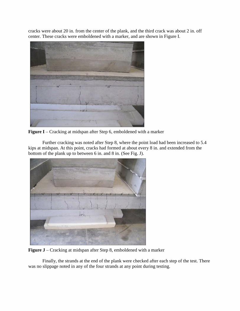
cracks were about 20 in. from the center of the plank, and the third crack was about 2 in. off center. These cracks were emboldened with a marker, and are shown in Figure I.
Figure I – Cracking at midspan after Step 6, emboldened with a marker
Further cracking was noted after Step 8, where the point load had been increased to 5.4 kips at midspan. At this point, cracks had formed at about every 8 in. and extended from the bottom of the plank up to between 6 in. and 8 in. (See Fig. J).
Figure J – Cracking at midspan after Step 8, emboldened with a marker
Finally, the strands at the end of the plank were checked after each step of the test. There was no slippage noted in any of the four strands at any point during testing.
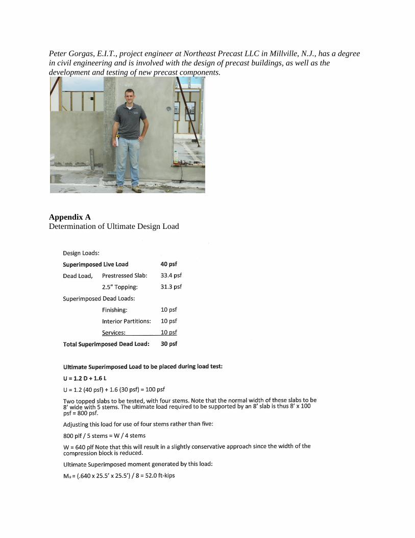
Peter Gorgas, E.I.T., project engineer at Northeast Precast LLC in Millville, N.J., has a degree in civil engineering and is involved with the design of precast buildings, as well as the development and testing of new precast components.
Appendix A Determination of Ultimate Design Load
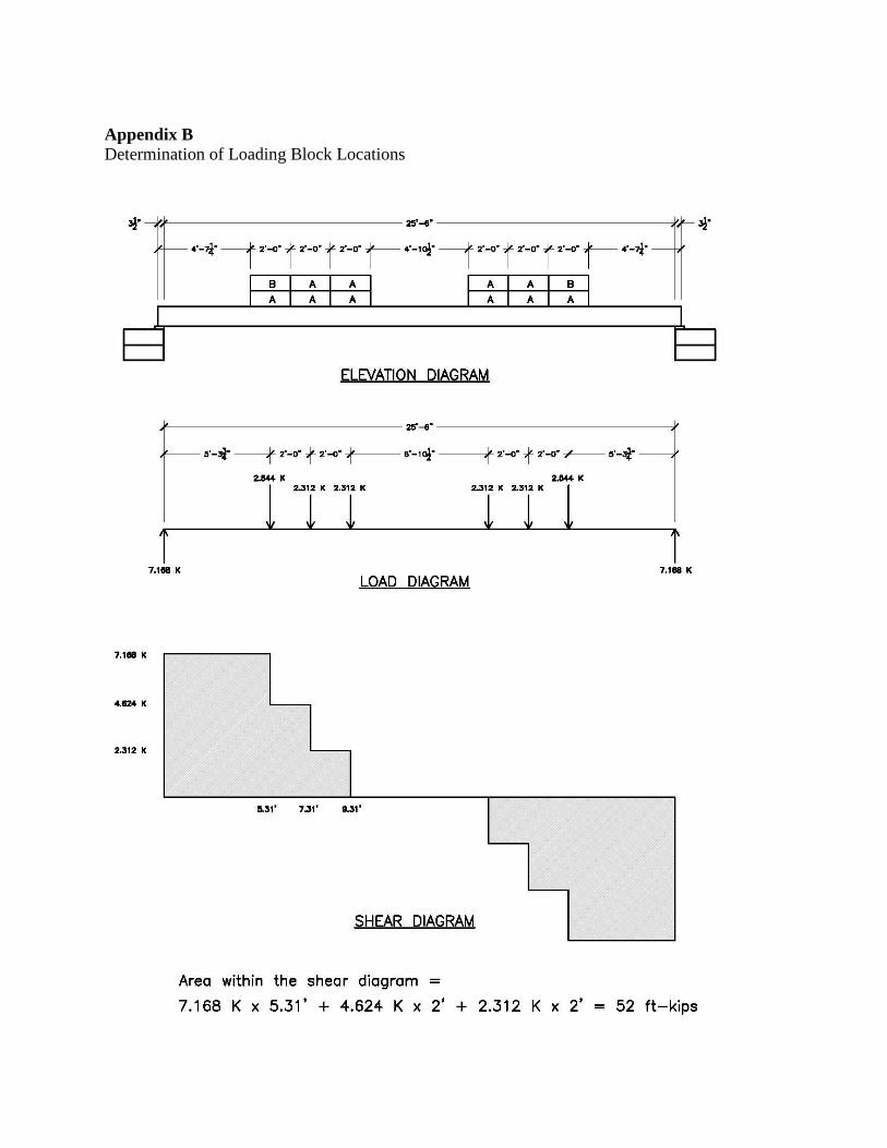
Appendix B Determination of Loading Block Locations
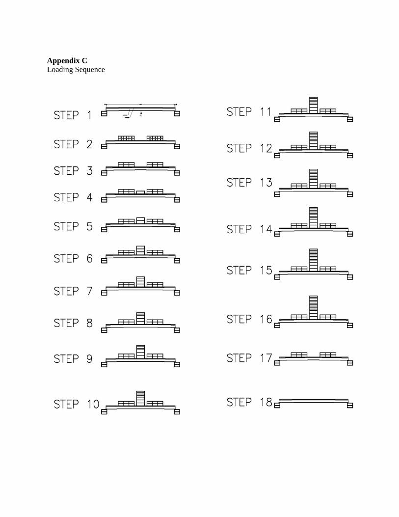
Appendix C Loading Sequence


![SECTION 034500 - PRECAST ARCHITECTURAL CONCRETE · Architectural precast concrete cladding [and load-bearing] units. ... PRECAST ARCHITECTURAL CONCRETE 034500 ... Architectural Cladding](https://img.pdfslide.net/doc/110x75/5ae006067f8b9a1c248cb77e/section-034500-precast-architectural-concrete-precast-concrete-cladding-and-load-bearing.jpg)