Embed Size (px)
Citation preview
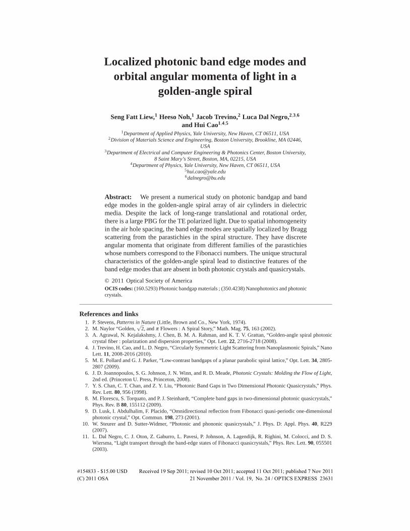
Localized photonic band edge modes andorbital angular momenta of light in a
golden-angle spiral
Seng Fatt Liew,1 Heeso Noh,1 Jacob Trevino,2 Luca Dal Negro,2,3,6
and Hui Cao1,4,5
1Department of Applied Physics, Yale University, New Haven, CT 06511, USA2Division of Materials Science and Engineering, Boston University, Brookline, MA 02446,
USA3Department of Electrical and Computer Engineering & Photonics Center, Boston University,
8 Saint Mary’s Street, Boston, MA, 02215, USA4Department of Physics, Yale University, New Haven, CT 06511, USA
[email protected]@bu.edu
Abstract: We present a numerical study on photonic bandgap and bandedge modes in the golden-angle spiral array of air cylinders in dielectricmedia. Despite the lack of long-range translational and rotational order,there is a large PBG for the TE polarized light. Due to spatial inhomogeneityin the air hole spacing, the band edge modes are spatially localized by Braggscattering from the parastichies in the spiral structure. They have discreteangular momenta that originate from different families of the parastichieswhose numbers correspond to the Fibonacci numbers. The unique structuralcharacteristics of the golden-angle spiral lead to distinctive features of theband edge modes that are absent in both photonic crystals and quasicrystals.
© 2011 Optical Society of AmericaOCIS codes: (160.5293) Photonic bandgap materials ; (350.4238) Nanophotonics and photoniccrystals.
References and links1. P. Stevens, Patterns in Nature (Little, Brown and Co., New York, 1974).2. M. Naylor “Golden,
√2, and π Flowers : A Spiral Story,” Math. Mag. 75, 163 (2002).
3. A. Agrawal, N. Kejalakshmy, J. Chen, B. M. A. Rahman, and K. T. V. Grattan, “Golden-angle spiral photoniccrystal fiber : polarization and dispersion properties,” Opt. Lett. 22, 2716-2718 (2008).
4. J. Trevino, H. Cao, and L. D. Negro, “Circularly Symmetric Light Scattering from Nanoplasmonic Spirals,” NanoLett. 11, 2008-2016 (2010).
5. M. E. Pollard and G. J. Parker, “Low-contrast bandgaps of a planar parabolic spiral lattice,” Opt. Lett. 34, 2805-2807 (2009).
6. J. D. Joannopoulos, S. G. Johnson, J. N. Winn, and R. D. Meade, Photonic Crystals: Molding the Flow of Light,2nd ed. (Princeton U. Press, Princeton, 2008).
7. Y. S. Chan, C. T. Chan, and Z. Y. Liu, “Photonic Band Gaps in Two Dimensional Photonic Quasicrystals,” Phys.Rev. Lett. 80, 956 (1998).
8. M. Florescu, S. Torquato, and P. J. Steinhardt, “Complete band gaps in two-dimensional photonic quasicrystals,”Phys. Rev. B 80, 155112 (2009).
9. D. Lusk, I. Abdulhalim, F. Placido, “Omnidirectional reflection from Fibonacci quasi-periodic one-dimensionalphotonic crystal,” Opt. Commun. 198, 273 (2001).
10. W. Steurer and D. Sutter-Widmer, “Photonic and phononic quasicrystals,” J. Phys. D: Appl. Phys. 40, R229(2007).
11. L. Dal Negro, C. J. Oton, Z. Gaburro, L. Pavesi, P. Johnson, A. Lagendijk, R. Righini, M. Colocci, and D. S.Wiersma, “Light transport through the band-edge states of Fibonacci quasicrystals,” Phys. Rev. Lett. 90, 055501(2003).
#154833 - $15.00 USD Received 19 Sep 2011; revised 10 Oct 2011; accepted 11 Oct 2011; published 7 Nov 2011(C) 2011 OSA 21 November 2011 / Vol. 19, No. 24 / OPTICS EXPRESS 23631
12. H. Vogel, “A better way to construct the sunflower head,” Math. Biosci. 44, 179 (1979).13. http://www.comsol.com
1. Introduction
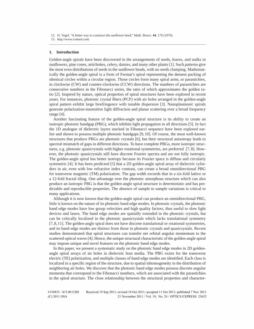
Golden-angle spirals have been discovered in the arrangements of seeds, leaves, and stalks insunflowers, pine cones, artichokes, celery, daisies, and many other plants [1]. Such patterns givethe most even distributions of seeds in the sunflower heads, with no seeds clumping. Mathemat-ically the golden-angle spiral is a form of Fermat’s spiral representing the densest packing ofidentical circles within a circular region. Those circles form many spiral arms, or parastichies,in clockwise (CW) and counter-clockwise (CCW) directions. The numbers of parastichies areconsecutive numbers in the Fibonacci series, the ratio of which approximates the golden ra-tio [2]. Inspired by nature, optical properties of spiral structures have been explored in recentyears. For instances, photonic crystal fibers (PCF) with air holes arranged in the golden-anglespiral pattern exhibit large birefringence with tunable dispersion [3]. Nanoplasmonic spiralsgenerate polarization-insensitive light diffraction and planar scattering over a broad frequencyrange [4].
Another fascinating feature of the golden-angle spiral structure is its ability to create anisotropic photonic bandgap (PBG), which inhibits light propagation in all directions [5]. In factthe 1D analogue of dielectric layers stacked in Fibonacci sequence have been explored ear-lier and shown to possess multiple photonic bandgaps [9, 10]. Of course, the most well-knownstructures that produce PBGs are photonic crystals [6], but their structural anisotropy leads tospectral mismatch of gaps in different directions. To have complete PBGs, more isotropic struc-tures, e.g. photonic quasicrystals with higher rotational symmetries, are preferred [7, 8]. How-ever, the photonic quasicrystals still have discrete Fourier spectra and are not fully isotropic.The golden-angle spiral has better isotropy because its Fourier space is diffuse and circularlysymmetric [4]. It has been predicted [5] that a 2D golden-angle spiral array of dielectric cylin-ders in air, even with low refractive index contrast, can create a broad omnidirectional PBGfor transverse magnetic (TM) polarization. The gap width exceeds that in a six-fold lattice ora 12-fold fractal tiling. One advantage over the photonic amorphous structure which can alsoproduce an isotropic PBG is that the golden-angle spiral structure is deterministic and has pre-dictable and reproducible properties. The absence of sample to sample variations is critical tomany applications.
Although it is now known that the golden-angle spiral can produce an omnidirectional PBG,little is known on the nature of its photonic band edge modes. In photonic crystals, the photonicband edge modes have low group velocities and high quality factors, thus useful to slow lightdevices and lasers. The band edge modes are spatially extended in the photonic crystals, butcan be critically localized in the photonic quasicrystals which lacks translational symmetry[7,8,11]. The golden-angle spiral does not have discrete translational or rotational symmetries,and its band edge modes are distinct from those in photonic crystals and quasicrystals. Recentstudies demonstrated that spiral structures can transfer net orbital angular momentum to thescattered optical waves [4]. Hence, the unique structural characteristic of the golden-angle spiralmay impose unique and novel features on the photonic band edge modes.
In this paper, we present a systematic study on the photonic band edge modes in 2D golden-angle spiral arrays of air holes in dielectric host media. The PBG exists for the transverseelectric (TE) polarization, and multiple classes of band edge modes are identified. Each class islocalized in a specific region of the structure, due to spatial inhomogeneity in the distribution ofneighboring air holes. We discover that the photonic band edge modes possess discrete angularmomenta that correspond to the Fibonacci numbers, which are associated with the parastichiesin the spiral structure. The close relationship between the structural properties and character-
#154833 - $15.00 USD Received 19 Sep 2011; revised 10 Oct 2011; accepted 11 Oct 2011; published 7 Nov 2011(C) 2011 OSA 21 November 2011 / Vol. 19, No. 24 / OPTICS EXPRESS 23632
istics of the photonic band edge modes is unveiled using the Fourier Bessel spatial analysis.The unique properties of the photonic band edge modes in the golden-angle spiral may lead toapplications in light emitting devices and optical sensors.
2. Structural analysis of the golden-angle spiral
The golden-angle spiral, also called the Vogel’s spiral, was first proposed by Vogel to simulatethe seeds distribution in a sunflower head [12]. The location of each seed or circle is specifiedby a simple generation rule and expressed in the polar coordinate (r,θ) as
r = b√
q , (1)
θ = qα , (2)
where q = 0,1,2, . . . is an integer, b is a constant scaling factor, α = 360◦/φ 2 ≈ 137.508◦ is anirrational number known as the “golden angle”, φ = [1+51/2]/2 = 1.6180339 . . . is the goldenratio. The value of φ is approached by the ratio of two consecutive numbers in the Fibonacciseries (1,2,3,5,8,13,21,34,55,89,144, . . .). With this generation rule, the qth circle is rotatedazimuthally by the angle α from the location of the (q− 1)th one, and also pushed radiallyaway from the origin by a distance Δr = b
(√q−√
q−1).
Figure 1(a) shows a golden-angle spiral that consists of N = 1000 circles. Visually there aremultiple families of spiral arms formed by the circles. Within each family, the spiral arms, alsocalled parastichies, are regularly spaced. Some of the families have parastichies all twisting inthe CW direction, and the others in the CCW direction. The families are all intertwined. Thenumber of parastichies in every family is a Fibonacci number [2].
The 2D spatial Fourier spectrum of the golden-angle spiral is shown in Fig. 1(b). It has a con-tinuous background, on top of which are discrete concentric rings. The isotropy of the Fourierspace reflects the structural isotropy. The diffuse background in the Fourier space indicates thegolden-angle spiral is not a quasicrystal, but has many more spatial frequency components [4].The radii of discrete rings correspond to the dominant spatial frequencies of the structure. Weextract the distance between neighboring particles d by performing the Delaunay triangulationon the spiral array. In Fig. 1(c), each line segment connects two neighboring circles, and itslength d is color coded. The statistical distribution of d in Fig. 1(d) is broad and non-Gaussian.d is normalized by d0, the most probable value of d where the distribution is peaked. d0 scaleslinearly with b, as shown in [4]. The broad distribution of d is consistent with the rich Fourierspectrum. The brightest ring in the Fourier space, which is also the smallest, has a radius closeto 2π/do. The non-uniform color distribution in Fig. 1(c) reveals the spatial variation of neigh-boring particles spacing in the spiral structure. This special type of spatial inhomogeneity isa distinctive feature of the golden-angle spiral, and it has a significant impact on its opticalresonances as will be shown later.
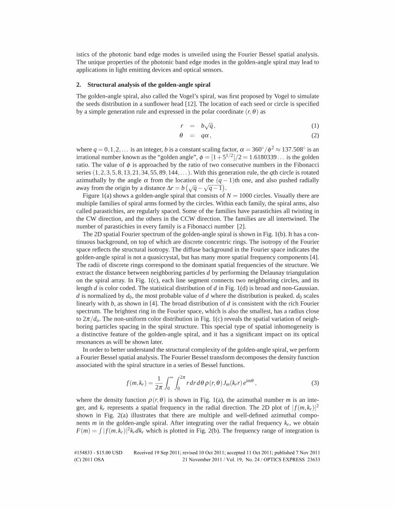
In order to better understand the structural complexity of the golden-angle spiral, we performa Fourier Bessel spatial analysis. The Fourier Bessel transform decomposes the density functionassociated with the spiral structure in a series of Bessel functions.
f (m,kr) =1
2π
∫ ∞
0
∫ 2π
0r drdθ ρ(r,θ)Jm(krr)eimθ , (3)
where the density function ρ(r,θ) is shown in Fig. 1(a), the azimuthal number m is an inte-ger, and kr represents a spatial frequency in the radial direction. The 2D plot of | f (m,kr)|2shown in Fig. 2(a) illustrates that there are multiple and well-defined azimuthal compo-nents m in the golden-angle spiral. After integrating over the radial frequency kr, we obtainF(m) =
∫ | f (m,kr)|2krdkr which is plotted in Fig. 2(b). The frequency range of integration is
#154833 - $15.00 USD Received 19 Sep 2011; revised 10 Oct 2011; accepted 11 Oct 2011; published 7 Nov 2011(C) 2011 OSA 21 November 2011 / Vol. 19, No. 24 / OPTICS EXPRESS 23633
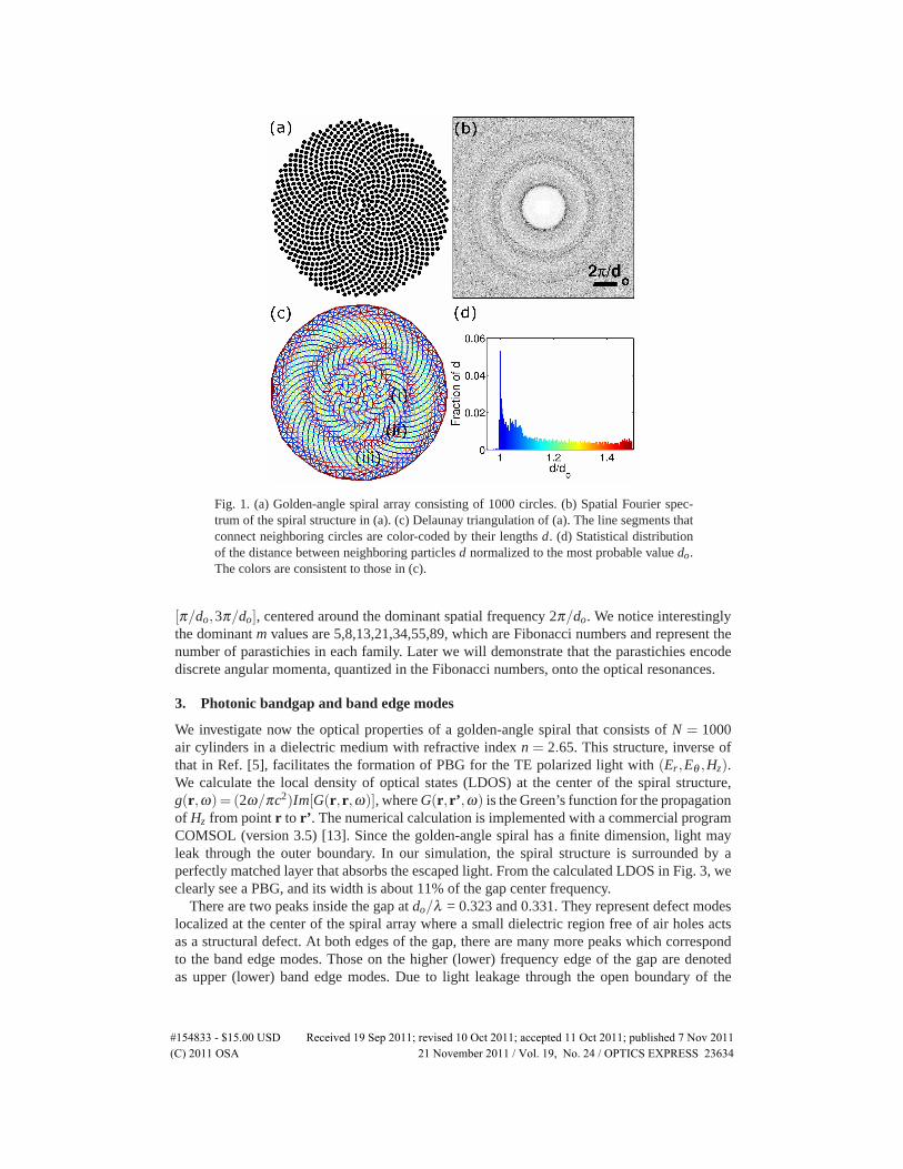
Fig. 1. (a) Golden-angle spiral array consisting of 1000 circles. (b) Spatial Fourier spec-trum of the spiral structure in (a). (c) Delaunay triangulation of (a). The line segments thatconnect neighboring circles are color-coded by their lengths d. (d) Statistical distributionof the distance between neighboring particles d normalized to the most probable value do.The colors are consistent to those in (c).
[π/do,3π/do], centered around the dominant spatial frequency 2π/do. We notice interestinglythe dominant m values are 5,8,13,21,34,55,89, which are Fibonacci numbers and represent thenumber of parastichies in each family. Later we will demonstrate that the parastichies encodediscrete angular momenta, quantized in the Fibonacci numbers, onto the optical resonances.
3. Photonic bandgap and band edge modes
We investigate now the optical properties of a golden-angle spiral that consists of N = 1000air cylinders in a dielectric medium with refractive index n = 2.65. This structure, inverse ofthat in Ref. [5], facilitates the formation of PBG for the TE polarized light with (Er,Eθ ,Hz).We calculate the local density of optical states (LDOS) at the center of the spiral structure,g(r,ω)= (2ω/πc2)Im[G(r,r,ω)], where G(r,r’,ω) is the Green’s function for the propagationof Hz from point r to r’. The numerical calculation is implemented with a commercial programCOMSOL (version 3.5) [13]. Since the golden-angle spiral has a finite dimension, light mayleak through the outer boundary. In our simulation, the spiral structure is surrounded by aperfectly matched layer that absorbs the escaped light. From the calculated LDOS in Fig. 3, weclearly see a PBG, and its width is about 11% of the gap center frequency.
There are two peaks inside the gap at do/λ = 0.323 and 0.331. They represent defect modeslocalized at the center of the spiral array where a small dielectric region free of air holes actsas a structural defect. At both edges of the gap, there are many more peaks which correspondto the band edge modes. Those on the higher (lower) frequency edge of the gap are denotedas upper (lower) band edge modes. Due to light leakage through the open boundary of the
#154833 - $15.00 USD Received 19 Sep 2011; revised 10 Oct 2011; accepted 11 Oct 2011; published 7 Nov 2011(C) 2011 OSA 21 November 2011 / Vol. 19, No. 24 / OPTICS EXPRESS 23634
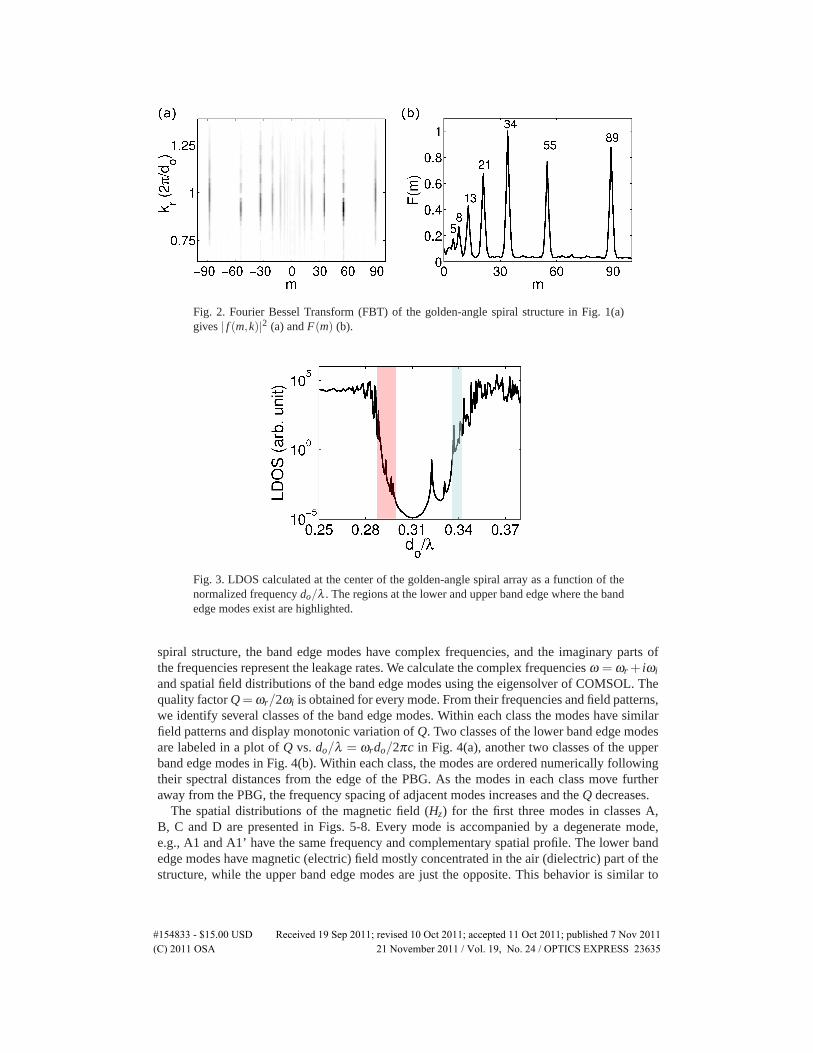
Fig. 2. Fourier Bessel Transform (FBT) of the golden-angle spiral structure in Fig. 1(a)gives | f (m,k)|2 (a) and F(m) (b).
Fig. 3. LDOS calculated at the center of the golden-angle spiral array as a function of thenormalized frequency do/λ . The regions at the lower and upper band edge where the bandedge modes exist are highlighted.
spiral structure, the band edge modes have complex frequencies, and the imaginary parts ofthe frequencies represent the leakage rates. We calculate the complex frequencies ω = ωr + iωi
and spatial field distributions of the band edge modes using the eigensolver of COMSOL. Thequality factor Q=ωr/2ωi is obtained for every mode. From their frequencies and field patterns,we identify several classes of the band edge modes. Within each class the modes have similarfield patterns and display monotonic variation of Q. Two classes of the lower band edge modesare labeled in a plot of Q vs. do/λ = ωrdo/2πc in Fig. 4(a), another two classes of the upperband edge modes in Fig. 4(b). Within each class, the modes are ordered numerically followingtheir spectral distances from the edge of the PBG. As the modes in each class move furtheraway from the PBG, the frequency spacing of adjacent modes increases and the Q decreases.
The spatial distributions of the magnetic field (Hz) for the first three modes in classes A,B, C and D are presented in Figs. 5-8. Every mode is accompanied by a degenerate mode,e.g., A1 and A1’ have the same frequency and complementary spatial profile. The lower bandedge modes have magnetic (electric) field mostly concentrated in the air (dielectric) part of thestructure, while the upper band edge modes are just the opposite. This behavior is similar to
#154833 - $15.00 USD Received 19 Sep 2011; revised 10 Oct 2011; accepted 11 Oct 2011; published 7 Nov 2011(C) 2011 OSA 21 November 2011 / Vol. 19, No. 24 / OPTICS EXPRESS 23635
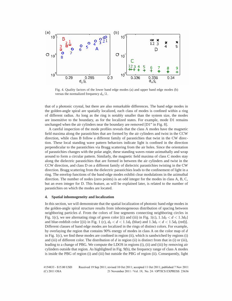
Fig. 4. Quality factors of the lower band edge modes (a) and upper band edge modes (b)versus the normalized frequency do/λ .
that of a photonic crystal, but there are also remarkable differences. The band edge modes inthe golden-angle spiral are spatially localized, each class of modes is confined within a ringof different radius. As long as the ring is notably smaller than the system size, the modesare insensitive to the boundary, as for the localized states. For example, mode D1 remainsunchanged when the air cylinders near the boundary are removed [D1” in Fig. 8].
A careful inspection of the mode profiles reveals that the class A modes have the magneticfield maxima along the parastichies that are formed by the air cylinders and twist in the CCWdirection, while class B follow a different family of parastichies that twist in the CW direc-tion. These local standing wave pattern behaviors indicate light is confined in the directionperpendicular to the parastichies via Bragg scattering from the air holes. Since the orientationof parastichies changes with the polar angle, these standing waves rotate azimuthally and wraparound to form a circular pattern. Similarly, the magnetic field maxima of class C modes stayalong the dielectric parastichies that are formed in between the air cylinders and twist in theCCW direction, and class D on a different family of dielectric parastichies twisting in the CWdirection. Bragg scattering from the dielectric parastichies leads to the confinement of light in aring. The envelop functions of the band edge modes exhibit clear modulations in the azimuthaldirection. The number of nodes (zero points) is an odd integer for the modes in class A, B, C,but an even integer for D. This feature, as will be explained later, is related to the number ofparastichies on which the modes are located.
4. Spatial inhomogeneity and localization
In this section, we will demonstrate that the spatial localization of photonic band edge modes inthe golden-angle spiral structure results from inhomogeneous distribution of spacing betweenneighboring particles d. From the colors of line segments connecting neighboring circles inFig. 1(c), we see alternating rings of green color [(i) and (iii) in Fig. 1(c), 1.1d0 < d < 1.3d0]and blue-reddish color [(ii) in Fig. 1 (c), d0 < d < 1.1d0 (blue) and 1.3d0 < d < 1.5d0 (red)].Different classes of band edge modes are localized in the rings of distinct colors. For example,by overlaying the region that contains 90% energy of modes in class A on the color map of din Fig. 1(c), we find these modes are confined in region (ii), which is sandwiched by regions (i)and (iii) of different color. The distribution of d in region (ii) is distinct from that in (i) or (iii),leading to a change of PBG. We compute the LDOS in regions (i), (ii) and (iii) by removing aircylinders outside that region. As highlighted in Fig. 9(b), the frequency range of class A modesis inside the PBG of region (i) and (iii) but outside the PBG of region (ii). Consequently, light
#154833 - $15.00 USD Received 19 Sep 2011; revised 10 Oct 2011; accepted 11 Oct 2011; published 7 Nov 2011(C) 2011 OSA 21 November 2011 / Vol. 19, No. 24 / OPTICS EXPRESS 23636
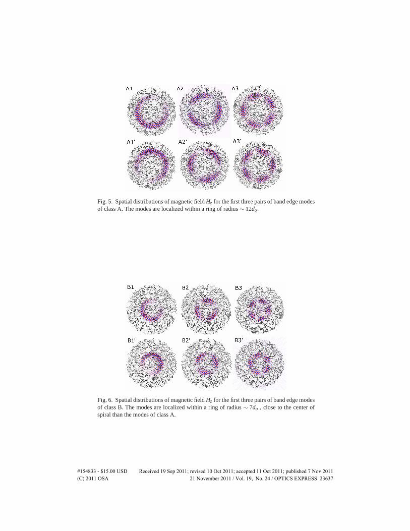
Fig. 5. Spatial distributions of magnetic field Hz for the first three pairs of band edge modesof class A. The modes are localized within a ring of radius ∼ 12do.
Fig. 6. Spatial distributions of magnetic field Hz for the first three pairs of band edge modesof class B. The modes are localized within a ring of radius ∼ 7do , close to the center ofspiral than the modes of class A.
#154833 - $15.00 USD Received 19 Sep 2011; revised 10 Oct 2011; accepted 11 Oct 2011; published 7 Nov 2011(C) 2011 OSA 21 November 2011 / Vol. 19, No. 24 / OPTICS EXPRESS 23637
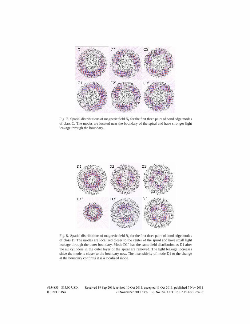
Fig. 7. Spatial distributions of magnetic field Hz for the first three pairs of band edge modesof class C. The modes are located near the boundary of the spiral and have stronger lightleakage through the boundary.
Fig. 8. Spatial distributions of magnetic field Hz for the first three pairs of band edge modesof class D. The modes are localized closer to the center of the spiral and have small lightleakage through the outer boundary. Mode D1” has the same field distribution as D1 afterthe air cylinders in the outer layer of the spiral are removed. The light leakage increasessince the mode is closer to the boundary now. The insensitivity of mode D1 to the changeat the boundary confirms it is a localized mode.
#154833 - $15.00 USD Received 19 Sep 2011; revised 10 Oct 2011; accepted 11 Oct 2011; published 7 Nov 2011(C) 2011 OSA 21 November 2011 / Vol. 19, No. 24 / OPTICS EXPRESS 23638
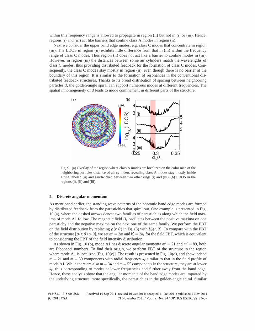
within this frequency range is allowed to propagate in region (ii) but not in (i) or (iii). Hence,regions (i) and (iii) act like barriers that confine class A modes in region (ii).
Next we consider the upper band edge modes, e.g. class C modes that concentrate in region(iii). The LDOS in region (ii) exhibits little difference from that in (iii) within the frequencyrange of class C modes. Thus region (ii) does not act like a barrier to confine modes in (iii).However, in region (iii) the distances between some air cylinders match the wavelengths ofclass C modes, thus providing distributed feedback for the formation of class C modes. Con-sequently, the class C modes stay mostly in region (ii), even though there is no barrier at theboundary of this region. It is similar to the formation of resonances in the conventional dis-tributed feedback structures. Thanks to its broad distribution of spacing between neighboringparticles d, the golden-angle spiral can support numerous modes at different frequencies. Thespatial inhomogeneity of d leads to mode confinement in different parts of the structure.
Fig. 9. (a) Overlay of the region where class A modes are localized on the color map of theneighboring particles distance of air cylinders revealing class A modes stay mostly insidea ring labeled (ii) and sandwiched between two other rings (i) and (iii). (b) LDOS in theregions (i), (ii) and (iii).
5. Discrete angular momentum
As mentioned earlier, the standing wave patterns of the photonic band edge modes are formedby distributed feedback from the parastichies that spiral out. One example is presented in Fig.10 (a), where the dashed arrows denote two families of parastichies along which the field max-ima of mode A1 follow. The magnetic field Hz oscillates between the positive maxima on oneparastichy and the negative maxima on the next one of the same family. We perform the FBTon the field distribution by replacing ρ(r,θ) in Eq. (3) with Hz(r,θ). To compare with the FBTof the structure [ρ(r,θ)> 0], we set m′ = 2m and k′r = 2kr for the field FBT, which is equivalentto considering the FBT of the field intensity distribution.
As shown in Fig. 10 (b), mode A1 has discrete angular momenta m′ = 21 and m′ = 89, bothare Fibonacci numbers. To find their origin, we perform FBT of the structure in the regionwhere mode A1 is localized [Fig. 10(c)]. The result is presented in Fig. 10(d), and show indeedm = 21 and m = 89 components with radial frequency kr similar to that in the field profile ofmode A1. While there are also m= 34 and m= 55 components in the structure, they are at lowerkr, thus corresponding to modes at lower frequencies and further away from the band edge.Hence, these analysis show that the angular momenta of the band edge modes are imparted bythe underlying structure, more specifically, the parastichies in the golden-angle spiral. Similar
#154833 - $15.00 USD Received 19 Sep 2011; revised 10 Oct 2011; accepted 11 Oct 2011; published 7 Nov 2011(C) 2011 OSA 21 November 2011 / Vol. 19, No. 24 / OPTICS EXPRESS 23639
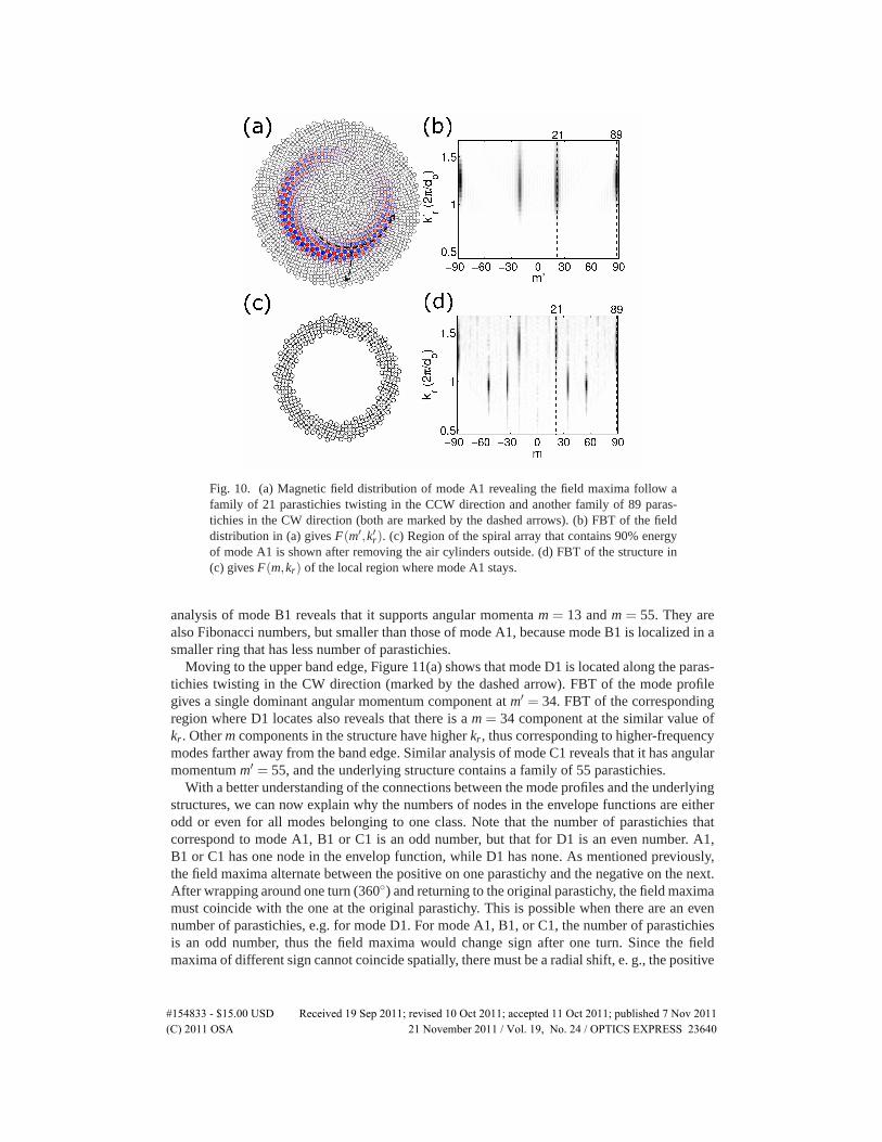
Fig. 10. (a) Magnetic field distribution of mode A1 revealing the field maxima follow afamily of 21 parastichies twisting in the CCW direction and another family of 89 paras-tichies in the CW direction (both are marked by the dashed arrows). (b) FBT of the fielddistribution in (a) gives F(m′,k′r). (c) Region of the spiral array that contains 90% energyof mode A1 is shown after removing the air cylinders outside. (d) FBT of the structure in(c) gives F(m,kr) of the local region where mode A1 stays.
analysis of mode B1 reveals that it supports angular momenta m = 13 and m = 55. They arealso Fibonacci numbers, but smaller than those of mode A1, because mode B1 is localized in asmaller ring that has less number of parastichies.
Moving to the upper band edge, Figure 11(a) shows that mode D1 is located along the paras-tichies twisting in the CW direction (marked by the dashed arrow). FBT of the mode profilegives a single dominant angular momentum component at m′ = 34. FBT of the correspondingregion where D1 locates also reveals that there is a m = 34 component at the similar value ofkr. Other m components in the structure have higher kr, thus corresponding to higher-frequencymodes farther away from the band edge. Similar analysis of mode C1 reveals that it has angularmomentum m′ = 55, and the underlying structure contains a family of 55 parastichies.
With a better understanding of the connections between the mode profiles and the underlyingstructures, we can now explain why the numbers of nodes in the envelope functions are eitherodd or even for all modes belonging to one class. Note that the number of parastichies thatcorrespond to mode A1, B1 or C1 is an odd number, but that for D1 is an even number. A1,B1 or C1 has one node in the envelop function, while D1 has none. As mentioned previously,the field maxima alternate between the positive on one parastichy and the negative on the next.After wrapping around one turn (360◦) and returning to the original parastichy, the field maximamust coincide with the one at the original parastichy. This is possible when there are an evennumber of parastichies, e.g. for mode D1. For mode A1, B1, or C1, the number of parastichiesis an odd number, thus the field maxima would change sign after one turn. Since the fieldmaxima of different sign cannot coincide spatially, there must be a radial shift, e. g., the positive
#154833 - $15.00 USD Received 19 Sep 2011; revised 10 Oct 2011; accepted 11 Oct 2011; published 7 Nov 2011(C) 2011 OSA 21 November 2011 / Vol. 19, No. 24 / OPTICS EXPRESS 23640
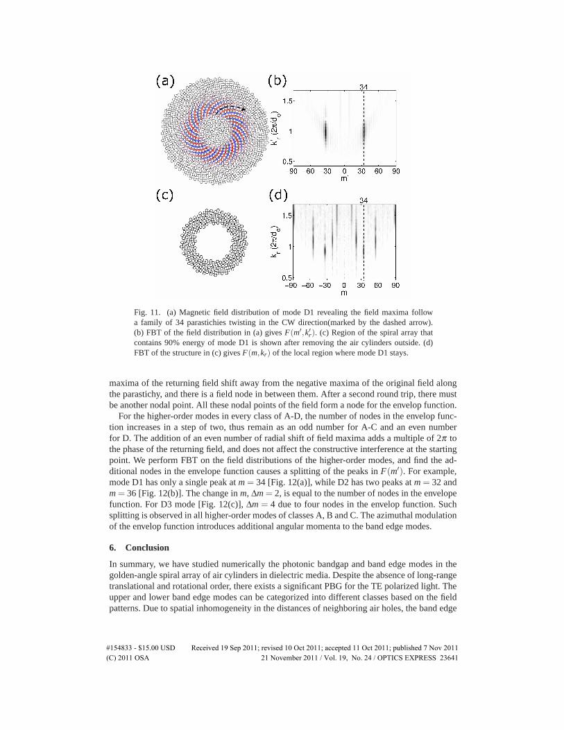
Fig. 11. (a) Magnetic field distribution of mode D1 revealing the field maxima followa family of 34 parastichies twisting in the CW direction(marked by the dashed arrow).(b) FBT of the field distribution in (a) gives F(m′,k′r). (c) Region of the spiral array thatcontains 90% energy of mode D1 is shown after removing the air cylinders outside. (d)FBT of the structure in (c) gives F(m,kr) of the local region where mode D1 stays.
maxima of the returning field shift away from the negative maxima of the original field alongthe parastichy, and there is a field node in between them. After a second round trip, there mustbe another nodal point. All these nodal points of the field form a node for the envelop function.
For the higher-order modes in every class of A-D, the number of nodes in the envelop func-tion increases in a step of two, thus remain as an odd number for A-C and an even numberfor D. The addition of an even number of radial shift of field maxima adds a multiple of 2π tothe phase of the returning field, and does not affect the constructive interference at the startingpoint. We perform FBT on the field distributions of the higher-order modes, and find the ad-ditional nodes in the envelope function causes a splitting of the peaks in F(m′). For example,mode D1 has only a single peak at m = 34 [Fig. 12(a)], while D2 has two peaks at m = 32 andm = 36 [Fig. 12(b)]. The change in m, Δm = 2, is equal to the number of nodes in the envelopefunction. For D3 mode [Fig. 12(c)], Δm = 4 due to four nodes in the envelop function. Suchsplitting is observed in all higher-order modes of classes A, B and C. The azimuthal modulationof the envelop function introduces additional angular momenta to the band edge modes.
6. Conclusion
In summary, we have studied numerically the photonic bandgap and band edge modes in thegolden-angle spiral array of air cylinders in dielectric media. Despite the absence of long-rangetranslational and rotational order, there exists a significant PBG for the TE polarized light. Theupper and lower band edge modes can be categorized into different classes based on the fieldpatterns. Due to spatial inhomogeneity in the distances of neighboring air holes, the band edge
#154833 - $15.00 USD Received 19 Sep 2011; revised 10 Oct 2011; accepted 11 Oct 2011; published 7 Nov 2011(C) 2011 OSA 21 November 2011 / Vol. 19, No. 24 / OPTICS EXPRESS 23641
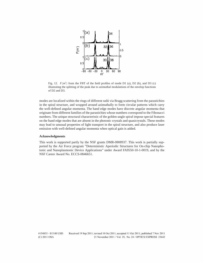
Fig. 12. F(m′) from the FBT of the field profiles of mode D1 (a), D2 (b), and D3 (c)illustrating the splitting of the peak due to azimuthal modulations of the envelop functionsof D2 and D3.
modes are localized within the rings of different radii via Bragg scattering from the parastichiesin the spiral structure, and wrapped around azimuthally to form circular patterns which carrythe well-defined angular momenta. The band edge modes have discrete angular momenta thatoriginate from different families of the parastichies whose numbers correspond to the Fibonaccinumbers. The unique structural characteristic of the golden-angle spiral impose special featureson the band edge modes that are absent in the photonic crystals and quasicrystals. These modesmay lead to unusual properties of light transport in the spiral structure, and also produce laseremission with well-defined angular momenta when optical gain is added.
Acknowledgments
This work is supported partly by the NSF grants DMR-0808937. This work is partially sup-ported by the Air Force program ”Deterministic Aperiodic Structures for On-chip Nanopho-tonic and Nanoplasmonic Device Applications” under Award FA9550-10-1-0019, and by theNSF Career Award No. ECCS-0846651.
#154833 - $15.00 USD Received 19 Sep 2011; revised 10 Oct 2011; accepted 11 Oct 2011; published 7 Nov 2011(C) 2011 OSA 21 November 2011 / Vol. 19, No. 24 / OPTICS EXPRESS 23642


![Inorganic Photonic Microspheres with Localized Concentric ......multifunctional zinc oxide and alumina are used as building materials of PC shell,[30] and are chemically grown onto](https://img.pdfslide.net/doc/110x75/60e68a6e1b271a24485fd9cc/inorganic-photonic-microspheres-with-localized-concentric-multifunctional.jpg)
![Localized photonic band edge modes and orbital angular ...tio [2]. Inspired by nature, optical properties of spiral structures have been explored in recent years. For instances, photonic](https://img.pdfslide.net/doc/110x75/5f02b4cd7e708231d4059a96/localized-photonic-band-edge-modes-and-orbital-angular-tio-2-inspired-by.jpg)


![Absolutely Local Occupied and Excited Molecular Orbitals ...€¦ · extremely localized molecular orbital (ELMO) theory [23], and one of the characteristics is the transferability](https://img.pdfslide.net/doc/110x75/6048feb5048dad414956efdd/absolutely-local-occupied-and-excited-molecular-orbitals-extremely-localized.jpg)