Embed Size (px)
Citation preview

LOGAN WATER ALLIANCE
PLANNING STUDY 90-11-37
ALFRED STREET PUMP STATION SPS02 STAGE 1 – UPGRADE OPTIONS STUDY
AUG-12

Document Number: 7600-000-REP-PL-8128
90-11-37 Alfred St Planning Study.doc.docx Date issued: 03/05/2012 Page 2 of 33 Rev: 1.0
Approval Register
Date
Project Manager Submitted 03/05/2012
Management Team Review
Program Review
Controlled Document – Change Register
Revision Section
Changed Change Description Initial Date
A All First release for LWA review AMcF 16/03/2012
0 All Final AS 03/05/2/012
1 All Final with formatting CT/CC 01/08/2012

Document Number: 7600-000-REP-PL-8128
Alfred St Planning Study Date issued: 03/05/2012 Page 3 of 33 Rev: 1.0
TABLE OF CONTENTS
1. EXECUTIVE SUMMARY .................................................................................................................... 5
2. INTRODUCTION ................................................................................................................................ 6
2.1 Scope of study .................................................................................................................................... 6
2.2 Purpose of this document ................................................................................................................... 7
2.3 Description of existing plant ................................................................................................................ 7
2.3.1 Pump station history .................................................................................................................. 8
2.4 Base assumptions used in this evaluation ....................................................................................... 10
2.4.1 SPS02 Power consumption estimate ...................................................................................... 10
3. OPTIONS OUTLINE ......................................................................................................................... 11
3.1 Option 1 – Refurbish existing line shaft pumps ................................................................................ 11
3.2 Option 2 – Replace existing pumps with dry well submersible pumps ............................................. 12
3.3 Examination of HV metering – applicable to both options ................................................................ 13
4. COST ESTIMATES .......................................................................................................................... 15
4.1 Option 1 – Capital costs ................................................................................................................... 15
4.1.1 Electrical ................................................................................................................................... 15
4.1.2 Mechanical ............................................................................................................................... 15
4.1.3 Civil .......................................................................................................................................... 16
4.2 Option 1 – Operating costs ............................................................................................................... 16
4.3 Option 2 – Capital costs ................................................................................................................... 17
4.3.1 Electrical ................................................................................................................................... 17
4.3.2 Mechanical ............................................................................................................................... 17
4.3.3 Civil .......................................................................................................................................... 17
4.4 Option 2 – Operating costs ............................................................................................................... 17
4.5 Whole-of-life cost comparison .......................................................................................................... 17
5. QUALITATIVE OPTIONS ANALYSIS ............................................................................................. 19
5.1 Option 1 ............................................................................................................................................ 19
5.1.1 Workplace health and safety.................................................................................................... 19
5.1.2 Capital cost .............................................................................................................................. 21
5.1.3 Operational cost ....................................................................................................................... 22
5.1.4 People ...................................................................................................................................... 23
5.1.5 Reliability .................................................................................................................................. 23
5.1.6 Maintainability .......................................................................................................................... 24
5.1.7 Limitations / Constraints ........................................................................................................... 25
Document Number: 7600-000-REP-PL-8128
Alfred St Planning Study Date issued: 03/05/2012 Page 4 of 33 Rev: 1.0
5.1.8 Environmental .......................................................................................................................... 25
5.2 Option 2 ............................................................................................................................................ 26
5.2.1 Workplace health and safety.................................................................................................... 26
5.2.2 Capital cost .............................................................................................................................. 27
5.2.3 Operational cost ....................................................................................................................... 28
5.2.4 People ...................................................................................................................................... 28
5.2.5 Reliability .................................................................................................................................. 29
5.2.6 Maintainability .......................................................................................................................... 29
5.2.7 Limitations / Constraints ........................................................................................................... 30
5.2.8 Environmental .......................................................................................................................... 31
6. MULTI-CRITERIA EVALUATION .................................................................................................... 32
6.1 MCE Results ..................................................................................................................................... 32
7. CONCLUSIONS ............................................................................................................................... 34
8. RECOMMENDATIONS .................................................................................................................... 35
TABLES
Table 2-1: Pumped volume and head for power consumption comparison ................................................ 11
Table 3-1: Assessment of HV metering with LV motors ............................................................................. 13
Table 4-1: Whole of life cost comparison .................................................................................................... 18
Table 4-2: Whole of life sensitivity analysis................................................................................................. 19
Table 6-1: MCE assessment criteria and weightings .................................................................................. 32
Table 6-2: MCE results................................................................................................................................ 33
APPENDICES
Appendix A-1 Electrical upgrade options
Appendix A-2 Electrical options assessment drawings
Appendix A-3 Electrical options study cost estimates
Appendix A-4 HV LV tariff analysis
Appendix B Capital cost estimate
Appendix C Operational cost estimate
Appendix D Pump drawing
Appendix E Multi-criteria evaluation
Appendix F Minutes from workshop
Document Number: 7600-000-REP-PL-8128
Alfred St Planning Study Date issued: 03/05/2012 Page 5 of 33 Rev: 1.0
1. EXECUTIVE SUMMARY
This study has been undertaken to determine the best option for upgrading the Alfred Street Wastewater
Pump Station (SPS02). The upgrade is necessary to replace failing and aged assets that are considered no
longer serviceable, in terms of operational reliability, and in terms of current safety standards. This study
exclusively examines the following options:
1. Option 1 – refurbish the existing main pump station line shaft pumps, pipework and valves and
replace the motors and electrical switchgear with either:
a. Low voltage (LV) motors and variable speed drives (VSD) or
b. 3.3 kV motor and 3.3 kV VSDs.
2. Option 2 – remove existing line shaft pumps, drives and associated steelwork and replace with low
voltage dry mounted submersible type pumps. Connecting pipework and valves will also need to be
replaced as required. Replace switchgear and VSDs in low voltage.
A stakeholder consultation process, in the form of a workshop, was conducted as part of this study to identify
the criteria used for evaluation of these two options. The identified criteria has been used to conduct a
qualitative analysis. This analysis has then been used to further inform a quantitative multi-criteria evaluation
(MCE) of these options. The identified criteria used for this evaluation is given below:
1. Workplace health and safety
2. Capital cost
3. Operational cost
4. People
5. Reliability
6. Maintainability
7. Limitations & constraints
8. Environmental
This study concludes from both the MCE and a whole-of-life cost perspective Option 2 is the preferred
option. The net present value (NPV) analysis scores for the developed electrical options favour a LV
refurbishment with the site changed to high voltage (HV) metering. Although Option 2 has a capital cost of
$2,469,400 which is $391,400 more expensive than Option 1a, Option 2 has an NPV $585,746 lower than
Option 1a. The Option 2 capital cost is $360,600 lower than Option 1b and a NPV $2,907,324 lower than
Option 1b.
Option 1b also has operating costs significantly higher than the LV options due to the need for specialist HV
certified electricians to perform maintenance.

Document Number: 7600-000-REP-PL-8128
Alfred St Planning Study Date issued: 03/05/2012 Page 6 of 33 Rev: 1.0
2. INTRODUCTION
2.1 Scope of study
The Alfred Street Wastewater Pump Station (SPS02) is nearing the end of its life for much of the mechanical
and electrical equipment (refer previous reports1). This study has been undertaken to determine the best
option for upgrading the current facility. This study is referred to as Stage 1 – Mechanical and Electrical
Options analysis. Stage 2 is development of a design solution and budgetary costs based upon the
recommendations of this Stage 1 options analysis.
The upgrade has been identified by Allconnex Water (PIF – QP-2201) as being necessary to replace failing
and aged assets that are considered no longer serviceable, in terms of operational reliability, and in terms of
current safety standards.
This Stage 1 options analysis has assessed the following major options based upon current and future
operational demand for the station:
1. Option 1 – refurbish the existing main pump station line shaft pumps, pipework and valves and
replace the motors and electrical switchgear with either:
a. Low voltage motors and VSDs (low voltage is 415 or 690 V); or
b. 3.3 kV motor and 3.3 kV VSDs.
2. Option 2 – Remove existing line shaft pumps, drives and associated steelwork and replace with low
voltage dry mounted submersible type pumps. Connecting pipework and valves will also need to be
replaced as required. Replace switchgear and VSDs in low voltage.
Both options 1 and 2 have been considered in the following aspects:
All necessary upgrade works associated with the existing electrical infrastructure to enable any or all
pumps (main and bypass pump stations) to be operated at any time of day;
The cost benefit of importing the site power at HV compared with LV and the associated tariff
analysis;
Compliance with WH&S legislation by improving operational site safety associated with the
mechanical pump and electrical switchgear infrastructure;
Improving the overall reliability and availability of the plant, whilst combating the effects of aggressive
and corrosive gases in the atmosphere; and
Preparation of an NPV analysis of both options covering a 25 year life-cycle.
1 LWA report 901039-S-REP-ME-4000 (mechanical assessment) and 901039-S-REP-EL-6000 (electrical
assessment) dated May 2010

Document Number: 7600-000-REP-PL-8128
Alfred St Planning Study Date issued: 03/05/2012 Page 7 of 33 Rev: 1.0
The original work description included an additional item as follows.
Development of an integrated control strategy that manages and co-ordinates both pump stations
(main and bypass pump stations) with a view to minimising pumping costs, down-stream flow
management (hydraulic loading versus system retention (septicity));
The integrated control strategy has been comprehensively covered in a third party report by SCADA
Engineering Pty Ltd2 so has not been addressed in this study.
2.2 Purpose of this document
This document summarizes the method of analysis undertaken and the results from the study. The intended
purpose is to identify the best option for progression into detail design and to provide sufficient background
information so the assessment is clear and justified.
This document is not intended to form the basis of budgetary allocation. The cost estimates have only been
performed for a comparison between options with a accuracy no greater than +/- 30%, not to ascertain the
true cost of the upgrade works.
Only the options detailed in the Scope of Study above have been considered. Other options including the
“do nothing” option have not been assessed.
2.3 Description of existing plant
The Alfred Street wastewater pump station is located on the west side of the Pacific Highway at Slacks
Creek, on the corner of Alfred Street and Nujooloo Road. The pumping station takes flows from its
designated catchment and pumps to the Loganholme WWTP. The site at Alfred Street contains both the
original pumping station, SPS02 and a newer Bypass Pumping Station, SPS069. A schematic of the station
and its associated rising mains is shown in Figure 2-1. The pump station under consideration here is the
original one, SPS02 and consists of a wet well and a dry well, with three vertical shaft split-case pumps
mounted in the base of the dry well. The 620 kW drive motors are located in the pump house at the top of
the dry well and the pumps are driven by vertical power shafts. The pumps are designated as Pump 1, Pump
2 and Pump 3.
During regular inflow periods a single pump is placed in operation, with each of the three pumps used on a
rotational basis to equalise the operating hours of each pump. During high inflow periods, Pump 1 is placed
in continuous operation and supplemented by either Pump 2 or Pump 3. Pumps 2 and 3 cannot be run
together as the pump 2 MCC is supplied via the pump 3 MCC. The pump 3 MCC is designed to carry the
load of one pump only.
2 Alfred Street SPS02 and SPS69 Waste Water Pump Stations – Control System Overview by SCADA
Engineering Pt Ltd dated 26/11/2011

Document Number: 7600-000-REP-PL-8128
Alfred St Planning Study Date issued: 03/05/2012 Page 8 of 33 Rev: 1.0
With the two pumps in high speed operation, the station has a capacity of approximately 2400L/s. The
motors of Pumps 1 and 2 are equipped with switchboard mounted soft starters; Pump 3 is fitted with an
integrated motor/VFD driver. The existing pumps have two speeds (high and low).
Two DN750 suction pipes draw from the wet well to a common suction manifold serving the three pumps.
The discharges of the pumps are cross connected and deliver to rising mains which discharge to the
Loganholme WWTP. The southern rising main is fitted with a manually operated bypass/recirculation line
that discharges back into the wet well.
The motor room and dry well is serviced by an overhead bridge crane that allows the motors and pumps to
be lifted. The crane capacity is 6.3 t safe working load. The crane does not extend outside the building and
there is no loading bay, so equipment must be lifted into the building by a mobile crane and then transferred
to the bridge crane for internal handling.
The dry well is ventilated by means of an extraction duct extending from the bottom of the dry well adjacent
to Pump 1 to the mezzanine level, where the extraction fan is fitted. A back-up diesel-powered generator is
located on site in its own specific enclosure adjacent to the pump station building. The generator has a name
plate capacity of 2200 kVA but has been tested to 2500 kVA. It generates in 240/415 V. This generator is
primarily used as a standby power source for the pump station but is also occasionally used by Energex to
feed power into the grid during exceptionally high demand periods.
A second, newer wastewater pump station SPS69 is also located on site. To date, SPS02 is the primary
pump station and SPS69 is the standby station. Current planning is to reverse these roles when the new
rising main is constructed.
A more comprehensive description of the infrastructure including photographs is contained in the previous
LWA report Mechanical Condition Assessment Alfred Street Sewage Pump Station.3
2.3.1 Pump station history
1984 – Pump station completed and entered into service with Pumps 1 and 2
1997 – Station capacity expanded with addition of Pump 3
2002 – Pump 2 refurbished by TKL
2006 – Pump 1 refurbished by Logan Water
2009 – Motor replaced on Pump 3, new replacement motor fitted with soft starter as per motors on
Pumps 1 and 2. Soft starter developed current problems and soon replaced with VFD
2011 – Pump 3 overhauled.
3 LWA report 901039-S-REP-ME-4000 dated May 2010.

Document Number: 7600-000-REP-PL-8128
Alfred St Planning Study Date issued: 03/05/2012 Page 9 of 33 Rev: 1.0
Figure 2-1: Schematic including proposed DN1200 rising main

Document Number: 7600-000-REP-PL-8128
Alfred St Planning Study Date issued: 03/05/2012 Page 10 of 58 Rev: 1.0
2.4 Base assumptions used in this evaluation
The following data are assumed to apply to all options evaluated.
1. There is a project currently underway to duplicate the rising main from Alfred Street SPS to the
Loganholme WWTP and to convert the current duty pumping station (the one under consideration
here) to the standby/wet weather pumping station. Design is complete but tendering and
construction is yet to start. This study is based on the assumption that this work will proceed and the
existing duty PS will become the back-up.
2. The general mode of operation pursuant to the above will be to operate the pumps for one period
during the day (peak power tariff) and for one period during the night (off-peak tariff) for a minimum
of 1 hour each run to change the volume in the line. These hours of operation will only be exceeded
when wet weather inflows exceed the capacity of the duty station (1400 L/s with the current pumps).
Refer to Section 2.4.1 for a more detailed discussion on power consumption estimation for this
study.
2.4.1 SPS02 Power consumption estimate
As SPS02 will become the standby pump station, it is not possible to use historical power consumption
figures for future cost estimation. During dry weather, the pump station will only operate twice a day and
pump only 2 megalitres through the two old rising mains to ensure their daily turn-over. Flow rate was
assumed at 600 L/s meaning it can pump this volume in just under an hour.
Wet weather will result in SPS02 coming on line only when SPS69 cannot keep up with inflows. It would be
possible to do a rigorous analysis of the flow split between the stations if historical data is available.
However, as a rigorous analysis is not within the current study scope, a simple analysis was undertaken
based on rainfall records. It was assumed that part time wet weather pumping would be required when
rainfall exceeds 10 mm per day and that full time pumping would be needed when it exceeds 30 mm per
day. Historically, there are an average of 22 days per year when rainfall is between 10 and 30 mm and 9
days per year when it exceeds 30. For the part time pumping, it was assumed the station pumps for 12
hours a day at 1200 L/s and for full time pumping, the assumption was 1200 L/s for 24 hours per day (or
2400 L/s for 12 hours per day).
The above assumptions yielded the following volumes to be pumped per year. Pump head varies as it was
assumed flow rate will vary, given that VSDs are to be installed. Power consumption is then simply a function
of volume, head and total (pump and electrical) efficiency.
Document Number: 7600-000-REP-PL-8128
Alfred St Planning Study Date issued: 03/05/2012 Page 11 of 58 Rev: 1.0
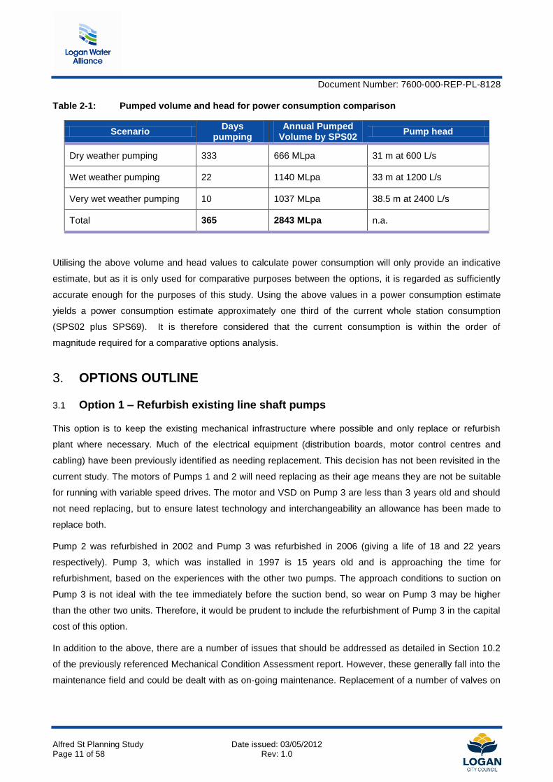
Table 2-1: Pumped volume and head for power consumption comparison
Scenario Days
pumping Annual Pumped
Volume by SPS02 Pump head
Dry weather pumping 333 666 MLpa 31 m at 600 L/s
Wet weather pumping 22 1140 MLpa 33 m at 1200 L/s
Very wet weather pumping 10 1037 MLpa 38.5 m at 2400 L/s
Total 365 2843 MLpa n.a.
Utilising the above volume and head values to calculate power consumption will only provide an indicative
estimate, but as it is only used for comparative purposes between the options, it is regarded as sufficiently
accurate enough for the purposes of this study. Using the above values in a power consumption estimate
yields a power consumption estimate approximately one third of the current whole station consumption
(SPS02 plus SPS69). It is therefore considered that the current consumption is within the order of
magnitude required for a comparative options analysis.
3. OPTIONS OUTLINE
3.1 Option 1 – Refurbish existing line shaft pumps
This option is to keep the existing mechanical infrastructure where possible and only replace or refurbish
plant where necessary. Much of the electrical equipment (distribution boards, motor control centres and
cabling) have been previously identified as needing replacement. This decision has not been revisited in the
current study. The motors of Pumps 1 and 2 will need replacing as their age means they are not be suitable
for running with variable speed drives. The motor and VSD on Pump 3 are less than 3 years old and should
not need replacing, but to ensure latest technology and interchangeability an allowance has been made to
replace both.
Pump 2 was refurbished in 2002 and Pump 3 was refurbished in 2006 (giving a life of 18 and 22 years
respectively). Pump 3, which was installed in 1997 is 15 years old and is approaching the time for
refurbishment, based on the experiences with the other two pumps. The approach conditions to suction on
Pump 3 is not ideal with the tee immediately before the suction bend, so wear on Pump 3 may be higher
than the other two units. Therefore, it would be prudent to include the refurbishment of Pump 3 in the capital
cost of this option.
In addition to the above, there are a number of issues that should be addressed as detailed in Section 10.2
of the previously referenced Mechanical Condition Assessment report. However, these generally fall into the
maintenance field and could be dealt with as on-going maintenance. Replacement of a number of valves on

Document Number: 7600-000-REP-PL-8128
Alfred St Planning Study Date issued: 03/05/2012 Page 12 of 58 Rev: 1.0
the discharge side of the pump is recommended, so the cost of this work has been included in the capital
work estimate to ensure fair comparison between the options.
Under Option 1, there are two sub-options. These are to replace the motors and MCCs with either low
voltage (as is the current situation) or with high voltage equipment. High voltage (as per AS3000:2007) is
defined as 1000 volts or greater. If HV is selected, then Pump 3 motor and VSD will also need replacing.
For both LV and HV power supply, there will be modifications required to the building to fit in the necessary
switchboards. If HV metering and/or HV drives are chosen, then additional works will be required in the yard
external to the building. This would be a new Energex HV metering substation and (if HV drives are chosen)
a new HV switch room. These are discussed in more detail later in the report.
Electrical Upgrade options
The study included examination of different refurbishment options;
three options 415Ai, 415Bii and 415Biii, utilising low voltage motors retaining the existing transformer
configuration and the current LV metering
three options 415Bi, 415Bii and 415Biii utilising low voltage motors retaining the existing transformer
configuration but with HV metering
two options 415Ci and 415Cii with low voltage motors utilising a single 11kV/415V supply
transformer and HV metering, and
four options 3300A, 3300B, 3300Ci and 3300Cii for high voltage motors with high voltage metering
The options are discussed in more detail in Appendices A1, A2, A3 and A4, with the cost estimates
summarised in Table 3-1 below.
3.2 Option 2 – Replace existing pumps with dry well submersible pumps
This option will require the replacement of all the pumps and motors with dry mount submersible
pumps/motor units at the base of the dry well. Much of the pipework and fittings, from the suction elbow to
the discharge manifold, will also need replacement. This is because the layout and sizes of the new pumps
suction and discharge will not align with that of the current pumps.
Modifications to the building structure will also be required to accommodate the electrical boards and to allow
installation and removal of the much larger pump and motor units.
As the pumps are sealed units with mechanical seals, gland flushing water will not be required.
A constraint for the selection of the pumps is the lifting capacity and clear hook height (above the motor floor)
of the current bridge crane. Modifications of the building and even replacement of the crane can be carried
out, but these costs are best avoided if possible.

Document Number: 7600-000-REP-PL-8128
Alfred St Planning Study Date issued: 03/05/2012 Page 13 of 58 Rev: 1.0
Three pump manufacturers were approached seeking suitable dry mount submersibles. Of these only one
(Xylem – Flygt) was able to offer a pump that was light enough for the existing crane to lift. Section 5.2.7.2
contains more discussion on the pump selection with respect to cranage.
Electrical Upgrade options
The preferred electrical upgrade options identified for Option 1, following the undertaking of the NPV
analysis, will be applicable for application under option 2.
3.3 Examination of HV metering – applicable to both options
A study was undertaken to determine if converting the site to HV metering would result in net cost benefits.
HV metering reduces the on-going electrical tariffs and charges, so, while there is additional capital outlay,
this can be off-set against an annual saving. Appendix A4 details the HV and LV tariff values used for the
tariff comparison in this assessment. Table 3-1 utilises the electrical cost estimates (exclusive of on-costs
and construction contingency) of the options outlined in section 3.1 and applies a NPV analysis utilising the
saving from conversion of the facility to a HV metered site.
Table 3-1: Assessment of HV metering with LV motors
Description Electrical
works capital cost
Saving with HV metering
Present Value
Net Present Cost Rank
Option 415Ai 415V LV metering $912,800 $0 $912,000 6
Option 415Aii 415V LV metering $920,300 $0
$920,000 7
Option 415Aiii 415V LV metering $1,052,900 $0 $1,053,000 8
Option 415Bi 415V HV metering $1,197,300 $30,197 -$452,882 $744,000 1
Option 415Bii 415V HV metering $1,204,800 $30,197 -$452,882 $752,000 2
Option 415Biii 415V HV metering $1,337,400 $30,197 -$452,882 $885,000 5
Option 415Ci 415V HV metering $1,222,400 $30,197 -$452,882 $770,000 3
Option 415Cii 415V HV metering $1,259,900 $30,197 -$452,882 $807,000 4
Option 3300A HV metering $1,552,000 $30,197 -$452,882 $1,099,000 9
Option 3300B HV metering $1,718,000 $30,197 -$452,882 $1,265,000 11
Option 3300Ci HV metering $2,454,000 $30,197 -$452,882 $2,001,000 12
Option 3300Cii HV metering $1,699,500 $30,197 -$452,882 $1,247,000 10
NPV parameters Period 25 years
Net effective Disc Rate 4.39%

Document Number: 7600-000-REP-PL-8128
Alfred St Planning Study Date issued: 03/05/2012 Page 14 of 58 Rev: 1.0
The net effective discount rate of 4.39% is established by reducing the LWA adopted discount rate of 9.35%
by an inflation rate of 4.75%.
LV Motor option
While option 415Bi achieved a higher rank than option 415Bii, due to a marginal cost advantage, option
415Bii does not have a restriction to the maintenance access to the LV drives.
It is therefore recommended that the option 415Bii be carried forward for further study for Option 1a.
HV Motor option
While options 3300A and 3300Cii achieved a higher rank than option 3300B they do not have permanent
generator power available to both pump stations. Via an informal inquiry placed into Energex, Energex
indicated they only had 2 off 1MVA 11kV generators neither of which would likely be available in an
emergency situation.
It is therefore recommended that option 3300B be carried forward for further study for Option 1b.
Overall NPV analysis
The overall NPV analysis scores utilising the electrical cost estimates favour the LV refurbishment options
with the site changed to HV metering. While these options have a higher initial capital cost they have the
lowest NPV.
It is therefore recommended that the option 415Bii be carried forward for further study for option 2.
Document Number: 7600-000-REP-PL-8128
Alfred St Planning Study Date issued: 03/05/2012 Page 15 of 58 Rev: 1.0
4. COST ESTIMATES
The cost estimates have only been performed for a comparison between options, not to ascertain the true
cost of the upgrade works. They could not be considered as any more accurate than +/-30% and caution
should be exercised is using the estimates as a basis for budgetary allocation.
4.1 Option 1 – Capital costs
The capital cost of Option 1a (utilising electrical option 415Bii) is estimated at $2.08million. For Option 1b
(utilising electrical option 3300B) this rises to $2.83million. The distribution of costs is briefly given below and
the full cost estimate is included in Appendix B.
4.1.1 Electrical
The following criteria apply to the electrical estimates for the financial models:
Cable CAPEX estimates have been based on typical per meter rates for HV and LV sub-mains.
Energex metering substation cost estimates are assumed to be exclusively at the owner’s costs and
are based on indicative costs applied by Energex to comparable installations. No formal application
has been made to Energex to undertake a cost study to provide accurate budget estimates for this
site.
Equipment unit costs were sourced from in-house information, previous project experience and with
major equipment cost estimates sourced from key supplier budget quotations.
The location of the Energex HV metering substation is selected to avoid the rising main thrust block
as detailed on available construction documentation. Additional costs may be applicable should the
installed thrust block location not match the as-construction drawing location and the actual location
impacts on the selected Energex HV metering substation location.
The electrical component of the works, inclusive of on-costs and construction contingency, is estimated at
$1.26 million for Option 1a and at $1.94 million for Option 1b.
4.1.2 Mechanical
For Option 1a and 1b, it was assumed that Pumps 1 and 2 would not need significant work given that they
were reconditioned a few years ago. An allowance of $105,000 was included in the capital cost for the
refurbishment of Pump 3.
For the Option 1a, the motor for Pump 3 may still be in good condition and suitable for continued use as it
was installed and converted to VFD in 2009. The motors of Pumps 1 and 2 will need to be replaced at a cost
of $84,000 each as they are nearing the end of their life and will not be suitable for running with VFDs.
However, for consistency amongst the equipment, an allowance has been made to replace all three motors
in the estimate.
Document Number: 7600-000-REP-PL-8128
Alfred St Planning Study Date issued: 03/05/2012 Page 16 of 58 Rev: 1.0
For the Option 1b, all motors will need to be replaced at a similar cost to the LV motors mentioned above.
The other mechanical item that is included in the capital expenditure is the replacement of six valves due to
inoperability or poor condition.
Overall, the mechanical component is estimated at $720,000 including contingencies and other on costs.
4.1.3 Civil
For both Options 1a and 1b a new HV metering substation will need to be built on the site. There will be a
small amount of civil work clearing and levelling the site and providing a substation slab and fencing.
For the Option 1a, internal walls will need to be demolished and new ones built to provide an enlarged switch
room separated from the dry well. A raised floor from galvanized steel is also required for the proposed
bottom entry and exit electrical cubicles. New doorways will be required and single flight stairs internally and
externally will be needed to access the raised floor. The wall between the switch room and the motor room
will need to be extended up to the roof to seal the switch room from fumes generated in the pump well. For
Option 1a, the civil works is estimated at $90,000.
For Option 1b, the internal building works are generally not required as a new HV MCC will be constructed
externally on site. The cost of the demountable switch room and conduits is estimated at $210,000.
4.2 Option 1 – Operating costs
The main cost will be power supply and consumption. This will account for approximately $170,000 a year
based on the reduced pumping hours envisaged. There is very little difference between the LV and HV
options. Power consumption is therefore not a cost differentiator.
Once Pump 3 is refurbished, the pump life until next refurbishment or replacement could be expected to be
20 years or more, especially given that this station will become the standby. However, this pump model is no
longer manufactured, so maintenance costs will be higher than for one that has spare parts readily available.
It is typical to allow an average annual maintenance cost of 5% of the capital cost. For these pumps which
will require parts to be specially cast and machined, an annual allowance of 15% of the capital cost has been
included.
The third operating cost is staff based. It is anticipated that keeping the existing pumps running will be more
labour intensive than new pumps would be. It has been suggested that one additional maintenance staff
member will be required, but it is highly unlikely that an additional full time staff member will be needed. It
seems reasonable to assume the additional maintenance would not be more than 1 day per week (or 9
weeks per year). Therefore, an allowance of 20% of an assumed staff cost of $200,000 p.a. has been
included.
For the Option 1b, either one of the existing electricians would need to be trained and certified in HV works
or an additional electrician (staff member or contractor on call) would be required. Having a contractor on call
has been assumed at the annual cost of $100,000.

Document Number: 7600-000-REP-PL-8128
Alfred St Planning Study Date issued: 03/05/2012 Page 17 of 58 Rev: 1.0
So, in summary, the annual operating costs used in this study are as follows;
Option 1a $254,000; Option 1b $354,000
A break-down of the operating costs is included in Appendix C.
4.3 Option 2 – Capital costs
The capital cost of Option 2 (utilising electrical option 415Bii), inclusive of on-costs and construction
contingency, is estimated at $2.47 million. The distribution of costs is briefly given below and the full cost
estimate is included in Appendix B.
4.3.1 Electrical
The provisions outlined in section 4.1 apply equally to Option 2. The electrical cost will be similar to Option
1a. The cost of motors is included in the mechanical component.
4.3.2 Mechanical
The main cost for this option is the supply of the dry-mount submersible pump-motor units at about $150,000
each. Due to the differing suction size and differing discharge size and orientation, much of the pipework
adjoining the pumps will need to be replaced. The framework supporting the existing drive shafts will also
need removal from the well.
Overall, the capital cost of the mechanical works for this option is approximately $1,070,000.
4.3.3 Civil
The only civil works that are additional to that required for Option 1a is the raising of the bridge crane to
accommodate the tall pump-motor units. It has been assumed at this stage that this is a relatively straight
forward job as the crane only needs to go up about 300 mm and that there is room to do this without raising
the roof. If this assumption proves to be false, then there will be additional cost resulting. The civil works cost
is estimated at $120,000.
4.4 Option 2 – Operating costs
As stated previously, power costs are about the same for all options. In terms of maintenance costs, the cost
to maintain the new current model pumps has been assumed at 5% of the purchase cost per annum. No
additional staff (mechanical or electrical) should be required for this option as the power is LV and the pumps
will be serviced off-site.
The annual operating cost for Option 2 is estimated at $191,000.
4.5 Whole-of-life cost comparison
The three options were evaluated on a whole of life basis using net present value calculations. The life was
set at 25 years and the effective discount rate set at 4.39%( LWA discount rate of 9.35% less inflation rate of

Document Number: 7600-000-REP-PL-8128
Alfred St Planning Study Date issued: 03/05/2012 Page 18 of 58 Rev: 1.0
4.75%). The life is as given in the project brief and differs from the standard 40 years adopted in other LWA
planning studies. The 9.35% discount rate is based on the standard numbers used in the LWA for planning
purposes.
The following table shows the comparison amongst the options. Option 2 proves to be the lowest whole-of-
life cost despite having a higher capital cost than option 1a.
Table 4-1: Whole of life cost comparison
Option 1a - Existing pumps, new motors and MCC in LV
Effective Discount Rate 4.39% Life 25
Capital Cost $2,078,000
Annual O&M Cost $253,848
NPV $6,052,233
Option 1b - Existing pumps, new motors and MCC in HV
Effective Discount Rate 4.39%
Capital Cost $2,830,000
Annual O&M Cost $354,103
NPV $8,373,811
Option 2 - New dry mount submersibles and MCC in LV
Effective Discount Rate 4.39%
Capital Cost $2,469,400
Annual O&M Cost $191,434
NPV $5,466,487
Notes
9.35% Discount rate is from LWA planning spreadsheet based on Cardno report. Inflation rate allowance is 4.75%.
A sensitivity analysis was also carried out to determine how sensitive the results were to the parameters.
The altered parameters were a discount rate of 8% down from 9.35%, life basis of 15 years down from 25
years and removal of the allowance of additional maintenance staff from the operating costs.
Document Number: 7600-000-REP-PL-8128
Alfred St Planning Study Date issued: 03/05/2012 Page 19 of 58 Rev: 1.0
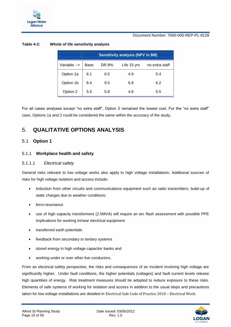
Table 4-2: Whole of life sensitivity analysis
Sensitivity analysis (NPV in $M)
Variable --> Base DR 8% Life 15 yrs no extra staff
Option 1a 6.1 6.5 4.9 5.4
Option 1b 8.4 9.0 6.8 6.2
Option 2 5.5 5.8 4.6 5.5
For all cases analyses except “no extra staff”, Option 2 remained the lowest cost. For the “no extra staff”
case, Options 1a and 2 could be considered the same within the accuracy of the study.
5. QUALITATIVE OPTIONS ANALYSIS
5.1 Option 1
5.1.1 Workplace health and safety
5.1.1.1 Electrical safety
General risks relevant to low voltage works also apply to high voltage installations. Additional sources of
risks for high voltage isolation and access include:
Induction from other circuits and communications equipment such as radio transmitters; build-up of
static charges due to weather conditions;
ferro-resonance
use of high capacity transformers (2.5MVA) will require an arc flash assessment with possible PPE
implications for working in/near electrical equipment
transferred earth potentials
feedback from secondary or tertiary systems
stored energy in high voltage capacitor banks and
working under or over other live conductors.
From an electrical safety perspective, the risks and consequences of an incident involving high voltage are
significantly higher. Under fault conditions, the higher potentials (voltages) and fault current levels release
high quantities of energy. Risk treatment measures should be adopted to reduce exposure to these risks.
Elements of safe systems of working for isolation and access in addition to the usual steps and precautions
taken for low voltage installations are detailed in Electrical Safe Code of Practice 2010 – Electrical Work.

Document Number: 7600-000-REP-PL-8128
Alfred St Planning Study Date issued: 03/05/2012 Page 20 of 58 Rev: 1.0
Electrical Safe Code of Practice 2010 – Electrical Work provides practical advice to discharge electrical
safety obligations. Including ways to identify and manage exposure to risks of injury and property damage
caused directly or indirectly, by electricity.
Isolation of and access to all areas containing high voltage equipment shall only be undertaken by personnel
specifically trained/instructed and authorized to undertake such works.
5.1.1.2 Confined space
According to AS2865-2009 Section 1.5.5, the pumps’ dry well is considered a confined space. The standard
stipulates that enough access openings should be provided to facilitate the retrieval of injured personnel from
the space. The current design does not allow for such provisions as it blocks the top access to the well
leaving limited space for verbal communication and spare parts handling.
Furthermore, the line shafts support structure further limits accessibility by the overhead crane to the well,
which would increase the hazards in handling spare parts and conducting repair work.
5.1.1.3 Working at heights
Maintenance of line shafts bearings requires working at heights; adequate platforms installed to facilitate
personnel access are currently fitted. Nonetheless, the access platforms do not eliminate the hazard of
working at heights due to the bearings locations and taking into account the frequency at which these
bearings need to be maintained, inspected and repaired.
5.1.1.4 Rotating machinery
Exposed rotating parts are a potential hazard to personnel. These could be grouped into two categories; the
first is the pumps’ couplings which can be accessed unintentionally while working on the dry well floor and
could be the higher risk category. The second is the line shaft bearings and parts and is a lesser risk
category due to guards being fitted.
If option 1 is adopted, then risk mitigation measures to reduce the potential hazard of these two categories
should be implemented. As a minimum, a guard must be installed to the pump drive shaft coupling.
5.1.1.5 Hazardous atmospheres
The condition assessment report compiled in 2010 noted that wastewater leaks were present in the pipework
and from the pump sealing glands, resulting in obnoxious gas generation. These gases are considered a
hazard to both human and material. They could cause asphyxiation to personnel accessing the plant and will
also accelerate equipment and material corrosion.
If Option 1 is adopted, then ventilation of the plant needs to be revisited as discussed in the asset condition
assessment report.

Document Number: 7600-000-REP-PL-8128
Alfred St Planning Study Date issued: 03/05/2012 Page 21 of 58 Rev: 1.0
5.1.1.6 Flooding risk
There is no difference between the options with respect to flooding from an external source (stormwater
flooding). Also, there is little difference between the options when it comes to flooding of the dry well from
pipe break. For Option 1, the motors and main electrical equipment are kept up at the motor room level and
will not be affected by the dry well filling.
5.1.1.7 Accessibility
Currently, the pumps, motors and shafts are lifted into the motor room by a mobile crane. From here the
internal bridge crane lifts and lowers the equipment into place. To lift out the pumps, the motors and drive
shafts must first be removed. This is time consuming but not inherently unsafe if correct procedures are
followed. The crane has a 3 metre clearance to the floor which gives ample room to move the equipment
around. This procedure does not need to change with proposed option 1.
5.1.1.8 Compartment segregation
It is necessary to seal/separate the electrical switch room from the dry well to minimise the effect of moisture
and corrosive H2S gasses on electrical components and equipment.
Compartment segregation can be achieved by using one of the following methods:
Extension of the switch room/drywell room separating wall to the roof line
Installation of a ceiling above the switch room
Introduction of positively pressurized ventilation system in conjunction with one of the two above
methods
Provision of a dedicated separate switch room building
The first of these alternatives has been adopted for costing purposes.
5.1.2 Capital cost
5.1.2.1 Pump cooling
The existing ventilation system appears to be adequate for the electric motors’ cooling. No capital
expenditure is expected if Option 1a or 1b is adopted. Some minor modifications might be necessary to
improve system performance but the cost of this is expected to be insignificant in relation to the scope of
options 1a or 1b.
5.1.2.2 IP/Ex rating of pump
The expected types of gases present in the pump station atmosphere are limited to the likes of hydrogen
sulfide, carbon dioxide and sulfur and nitrogen oxides: no hydrocarbons have been noticed or measured

Document Number: 7600-000-REP-PL-8128
Alfred St Planning Study Date issued: 03/05/2012 Page 22 of 58 Rev: 1.0
previously. These gases are not considered explosive, so no special explosion proof or similar electrical
equipment categories are required.
5.1.2.3 Accessibility
The existing bridge crane adequately services the dry well and this will continue to be the case with Option 1.
Drive shaft bearings are currently accessed by fixed walkways and this will continue.
5.1.2.4 Leveraging cost of existing assets
Although Pump 3 needs refurbishing, Pumps 1 and 2 will have many years of serviceable life before needing
refurbishment or replacement. The value of these existing assets will be retained with Option 1. The standby
generator is relatively new and will continue to be of use for the LV option. However, the HV alternative
renders this generator superfluous unless SPS69 is kept on LV supply. If the whole site is converted to HV,
then Energex may be interested in purchasing or leasing the generator to allow grid feed-in during high
demand times. An alternative would be to put in a step-up transformer and retain the generator.
Option 1a makes best use of existing assets while option 1b is somewhat worse due to the generator
redundancy.
5.1.3 Operational cost
5.1.3.1 Energy cost
The energy costs used to determine operation expenditure are based on the energy tariff and demand
criteria outlined in Appendix A4. There is little difference amongst all three options in terms of energy
demand, so this is not a differentiator.
5.1.3.2 Mechanical parts
Replacement parts, especially for the pumps in this option, are not available anymore from the pumps’
manufacturer due to their age. Parts due for replacement are specially manufactured at specialty
engineering workshops. As these parts are ordered as ‘one-off’, their cost is usually higher. There is also
additional maintenance team labour time involved. For these reasons, Option 1 will be more costly in terms
of mechanical parts than Option 2.
5.1.3.3 Labour
In addition to the labour cost required to specially manufacture repair parts for the pumps, maintenance
requirements are also relatively higher. The cost is due to the number of components requiring regular
attention, despite the fact that maintenance activities can be carried out on site. These activities include
attending to line shaft bearings, pumps’ glands, steel structure supporting the line shafts, etc.
5.1.3.4 Pump cooling
No additional operational cost is expected for this option. Refer discussion in section 5.1.2.1

Document Number: 7600-000-REP-PL-8128
Alfred St Planning Study Date issued: 03/05/2012 Page 23 of 58 Rev: 1.0
5.1.3.5 Carbon tax
A carbon tax allowance has not been considered in the financial calculations within this report as currently it
is unclear as to whom the tax will be applicable and as to how the penalties will be applied. However, it is
expected that there will be little difference between the options with respect to a carbon tax.
5.1.4 People
5.1.4.1 Availability of staff
Allconnex Water personnel are currently not qualified to undertake high voltage works. High voltage
connections and disconnections are currently undertaken by a contractor.
Pipework and pumps maintenance and repair is a daily routine the current staff is very familiar with; hence,
there are no staff availability issues regarding this area.
5.1.4.2 Training of staff
Installation of high voltage equipment will require employing new staff specialized in the trade. Plumbers and
pipework fitters can carry a limited license to undertake low voltage work; however, undertaking the required
training to carryout high voltage work is not common in the local workforce.
5.1.4.3 In-house knowledge
In-house knowledge dealing with the current pumps and their drive systems is readily available. On the other
hand, high voltage experience is an exotic theme that has to be either outsourced or introduced.
5.1.4.4 Succession planning
This issue cannot be qualified at that stage; plumbing and pipework in the pump station is an in-house
knowledge shared between an adequate number of staff members, which secures succession. To the
contrary, there is no high voltage in-house knowledge and the trade will have to be introduced.
5.1.4.5 Staff retention
Refurbishing the existing system will provide the existing workforce with a familiar environment. However, we
do not believe that they will agree to undertake high voltage training as carryout high voltage work is not
common in the local workforce.
5.1.5 Reliability
5.1.5.1 Redundancy
The options study has been undertaken with a view to allowing the main and by-pass pump stations to be
able to be operated electrically independently subject to network capacity limitations.
Document Number: 7600-000-REP-PL-8128
Alfred St Planning Study Date issued: 03/05/2012 Page 24 of 58 Rev: 1.0
The proposed Energex HV metering substation utilises a ring main unit and 1 high voltage meter for the HV
metering options. This configuration allows the site to maintain the current arrangement of having 2
independent points of supply from separate Energex substations.
The standby generation supply existing capacity was maintained for each option. Option 3300A investigated
the lower cost scenario of having generator supply only to the by-pass pumps station. Option 3300Cii
investigated the option of having a 11kV generator connection cubicle for use of a transportable transformer.
5.1.5.2 Interchangeability
Keeping the existing out-of-date pumps means that they are not interchangeable with current models and
need to be specially serviced. This means that a new pump cannot be brought in quickly and changed over
in the event of a catastrophic failure.
5.1.5.3 Pump cooling
Cooling requirements in this option are limited to the motors at ground level. The dry well does not require
any cooling. The current installed system is proven to be reliable and meets the pump station requirements.
If high-voltage motors are adopted and their variable speed drives require additional ventilation, the current
system will have to be reconfigured and augmented. This should not change the current ventilation system
reliability.
5.1.5.4 Flood risk
Flooding of the dry well does not present a serious issue to the pumps as the motors are located up on the
motor floor. Seals and bearings on the pump and drive shafts would need to be inspected and
repacked/replaced after the water is pumped out. For this reason, there would be a longer period out of
service following a flood than for Option 2.
5.1.6 Maintainability
5.1.6.1 On-site versus off-site maintenance
This option will not change the manner in which maintenance activities are conducted and its level. No
improvement or depreciation is expected.
5.1.6.2 Ability to do low-level maintenance using in-house staff
All low level maintenance works are currently carried out on site. High voltage motors might require extra
measures, i.e. disconnecting power from pumps, to allow low level maintenance activities.
5.1.6.3 Clearing chokes
This is a feature of the current pumps and is adequate for the purpose; no additional activities are required to
implement other similar feature.

Document Number: 7600-000-REP-PL-8128
Alfred St Planning Study Date issued: 03/05/2012 Page 25 of 58 Rev: 1.0
5.1.7 Limitations / Constraints
5.1.7.1 Building envelope
The building envelop does not present a constraint for this option. HV metering gear and HV switch room
(Option 1b) would be located external to the building.
5.1.7.2 Cranage
The current crane is suitable for Options 1a and 1b.
5.1.7.3 Structural issues
There are no structural issues identified with Option 1a and 1b. Some internal walls will need to be built or
demolished for Option 1a, but this does not present significant difficulty or cost.
5.1.7.4 Site restrictions
The site is reasonably constrained but there are two gates meaning vehicles accessing the pump house do
not need to turn around. The new HV metering yard and HV switch room (Option 1b) will fit on the site while
leaving adequate room for vehicular movements.
5.1.7.5 Power supply
Via an informal enquiry placed into Energex, Energex indicated that it is likely the existing network has
sufficient capacity available to run all three by-pass and main pump station pumps simultaneously. Formal
engagement of Energex to perform a load study is outside the scope of works for this stage of the options
study.
A risk does exist that the network may not have sufficient capacity to run all pumps simultaneously.
5.1.7.6 Noise
Refurbishment of the current system – whether high-voltage or low-voltage – will not increase the level of
noise above the current level except for the transformers noise. If high-voltage motors are adopted and their
variable speed drives require additional ventilation, extra noise level will be experienced. Nonetheless,
adequate attenuation could mitigate the issue.
5.1.8 Environmental
5.1.8.1 Reuse of plant
For the 415V option it is proposed to reuse the following existing electrical equipment associated with the
main pump station:
Standby 2250 kW diesel generator and associated manual transfer switch
Energex RMUs and transformers.
Document Number: 7600-000-REP-PL-8128
Alfred St Planning Study Date issued: 03/05/2012 Page 26 of 58 Rev: 1.0
It is proposed to retain the existing by-pass pump station electrical installation including the existing Energex
11 kV RMU and transformer.
Upon the site becoming a HV metered site the existing Energex RMUs and transformers can be transferred
to Allconnex Water after payment of the Energex calculated residual equipment value in lieu of Allconnex
Water providing new equipment.
5.1.8.2 Carbon footprint
There is little difference between the options with respect to power consumption, so this is not a
differentiating factor. Therefore, the differentiation in the carbon footprint will be governed by the greenhouse
gasses produced in manufacturing new plant and structures.
Option 1a reuses the existing pumps and one of the existing motors, so should inherently have a smaller
carbon footprint than Option 2.
The only other apparent difference among the options is that the HV option will require the removal of the
only significant trees on site to build the HV switch room.
5.2 Option 2
5.2.1 Workplace health and safety
5.2.1.1 Electrical safety
Refer section 5.1.1.1
5.2.1.2 Confined space
According to AS2865-2009 Section 1.5.5, the pumps’ dry well is considered a confined space. The standard
stipulates that enough access openings should be provided to facilitate the retrieval of injured personnel from
the space. The drywell submersible pumps option will allow for such provisions as it will clear the top access
to the well from any installed equipment and furthermore, remove the line shafts support structure.
5.2.1.3 Working at heights
Working at heights will be limited to the handling of the pumps when they are being installed or removed.
These events are considered infrequent, major operations rather than frequent maintenance activities.
5.2.1.4 Rotating machinery
All rotating parts will be enclosed inside the pump-motor assembly; no potential hazard to personnel from
rotating equipment is envisaged. All rotating elements will be enclosed with restricted access.
Document Number: 7600-000-REP-PL-8128
Alfred St Planning Study Date issued: 03/05/2012 Page 27 of 58 Rev: 1.0
5.2.1.5 Hazardous atmospheres
Given that the pumps and much of the pipework and fittings will be replaced in this option, the leakage of
wastewater into the well will be eliminated or greatly reduced. Therefore, the likelihood of the generation of a
hazardous atmosphere is greatly reduced compared with Option 1.
5.2.1.6 Flooding risk
For Option 2, the motors and cables leading to the motors are fully submersible, so no damage should occur
if the well floods. Therefore, this is not a differentiator between the options.
5.2.1.7 Accessibility
The pump/motor units are over 3 metres high, so there is little clearance below the bridge crane. The units
would need to be lifted into the motor room (by mobile crane) in a horizontal orientation. The bridge crane
would then need to stand it upright before it is lowered down the well. Tilting heavy equipment from
horizontal to vertical needs to be done carefully, to ensure the load does not swing. If the operator of the
bridge crane is not experienced, this could present a considerable hazard to safety. The structure could be
modified and the crane rails extended to outside the building, but that would not eliminated the risk as the
pump/motor unit will travel to site on the back of a truck in the horizontal position.
Please note: It could be argued that option 1 is less safe as there needs to be multiple lifts to remove a
pump. These multiple lifts are the motor and each segment of drive shaft. Each lift has a small risk
associated with it, so multiple lifts increase the overall exposure. However, it is felt that the heavy, tall
submersible pump/motors units for option 2 present more risk due to the nature of the lifts and the very
constrained (vertically) lifting environment.
5.2.1.8 Compartment segregation
The comments for Option 1a apply equally to Option 2. Refer section 5.1.1.8.
5.2.2 Capital cost
5.2.2.1 Pump cooling
Drywell submersible pumps use the pumped fluid to remove the heat generated by the drive motor; i.e. no
extra external cooling is required. The existing ventilation system could be dedicated to the VSD units.
5.2.2.2 IP/Exd rating of pump
The expected types of gases present in the pump station atmosphere are limited to the likes of hydrogen
sulfide, carbon dioxide and sulfur and nitrogen oxides; no hydrocarbons were noticed or measured before.
These gases are not considered explosive; thus, no special explosion proof or similar electrical equipment
categories are required.

Document Number: 7600-000-REP-PL-8128
Alfred St Planning Study Date issued: 03/05/2012 Page 28 of 58 Rev: 1.0
5.2.2.3 Accessibility
The bridge crane will have sufficient lifting capacity for the chosen pumps but will need to be raised in the
order of 300 mm to accommodate the height of the new pumps.
5.2.2.4 Leveraging cost of existing assets
As all pumps, motors and electrical equipment (and much of the pipework and fittings adjacent to the pumps)
are to be replaced; this option does not score well in terms of getting the most benefit from the existing
assets.
5.2.3 Operational cost
5.2.3.1 Energy cost
Refer Section 5.1.3.1
5.2.3.2 Mechanical parts
Spare parts for the new equipment should be readily available for at least the next 15 years. The supplier
should warrant their equipment for at least the first 2 years; this should eliminate the unscheduled
maintenance and repair cost. After the warranty period, the cost of parts is not expected to be as high as for
the current pumps.
5.2.3.3 Labour
Due to the configuration of the drywell submersible pumps, all maintenance and repair works will be carried
in a certified depot; this should reduce the load on the onsite personnel and thus cost. The labour cost
required to maintenance the existing line shafts components is eliminated.
5.2.3.4 Pump cooling
No additional operational cost is expected for this option. Refer discussion in section 5.1.3.4
5.2.3.5 Carbon tax
Comments for Option 1 apply equally to this option.
5.2.4 People
5.2.4.1 Availability of staff
Pipework and pumps maintenance and repair is a daily routine the current staff is very familiar with; hence,
there are no staff availability issues regarding this area. Plumbers and pipework fitters employed by
Allconnex Water mostly carries a limited license to undertake low voltage work connections and
disconnections.

Document Number: 7600-000-REP-PL-8128
Alfred St Planning Study Date issued: 03/05/2012 Page 29 of 58 Rev: 1.0
5.2.4.2 Training of staff
No extra staff training will be required; in-house knowledge is available for this option. Similar pumps
installed in Chetwynd St treatment plant are currently attended to by the same staff.
5.2.4.3 In-house knowledge
In-house knowledge dealing with drywell submersible pumps is readily available as discussed in the previous
subsection.
5.2.4.4 Succession planning
No succession planning is required as in-house knowledge is shared between an adequate number of staff
members.
5.2.4.5 Staff retention
The drywell submersible pumps option will provide the existing workforce with a familiar environment. Staff
retention would not be considered an issue in this case.
5.2.5 Reliability
5.2.5.1 Redundancy
Electrical Supply
Refer to section 5.1.5.1
5.2.5.2 Interchangeability
Option 2 rates higher than Option 1 as this option uses all new equipment to ensure interchangeability.
5.2.5.3 Pump cooling
Cooling requirements in this option are limited to providing an acceptable indoor environment. The current
installed system will be retained as it proved to be reliable and meets the pump station requirements. Minor
modifications might be required which will not affect the system reliability.
5.2.5.4 Flood risk
As the pumps and motors are submersible, the flooding of the well does not present much of a problem to
this option.
5.2.6 Maintainability
5.2.6.1 On-site versus off-site maintenance
This option should allow more maintenance activities to be conducted on site together with its level of
complexity. Nonetheless, special working area might be necessary to carry out such activities.

Document Number: 7600-000-REP-PL-8128
Alfred St Planning Study Date issued: 03/05/2012 Page 30 of 58 Rev: 1.0
5.2.6.2 Ability to do low-level maintenance using in-house staff
Undertaking low and medium level activities will be possible with the drywell submersible pumps as
conducted on other Allconnex Water sites.
5.2.6.3 Clearing chokes
This is a feature that can be specified for the proposed pumps if deemed required by Allconnex Water.
5.2.7 Limitations / Constraints
5.2.7.1 Building envelope
It is anticipated that the new equipment can be accommodated within the existing building envelope. The
only remaining risk is that the crane raising (see below) cannot be accommodate and that the roof will need
to be lifted slightly.
5.2.7.2 Crane
The chosen pump is 3060mm high from the base flange to the top of the lifting eye. The bridge crane on site
has a maximum hook clearance from the motor floor of 3000 to 3100 mm (approximate site measure).
Therefore, it is not practical to use the crane in its current configuration with the chosen pump. Possibilities
for rectifying the situation are:
1. Attempt to obtain a shorter motor that will fit in. Going to a higher voltage may reduce the motor
height but would require a special build for both the motor and the electrical equipment powering it.
2. Raise the crane running beams by 200 to 300 mm to ensure clearance. This may be possible
without lifting the roof but a detailed site measure would be required to confirm this.
3. Raise the roof and crane rails by say, 1000 mm to give plenty of clearance. Raising the roof may
require planning and building approval.
4. Cut a slot in the concrete motor room floor (and possibly in the well wall) to extend the end of the
current lifting void to the outside of the building. The crane rails would then need to be extended out
the side of the building so the crane could lift the pump to the vertical outside and then travel it in
through the slot before lowering it down the well. External posts (on piles to rock) would be needed
to support the ends of the new crane beams and possibly strengthening of the floor. Sealing/vermin
proofing the building wall through which the crane travels would also present considerable
challenges.
The second crane modification option is the most preferred and has been included in the cost estimate.
5.2.7.3 Structural issues
Provided the bridge crane can be raised sufficiently, there are no structural issues with this option.
Document Number: 7600-000-REP-PL-8128
Alfred St Planning Study Date issued: 03/05/2012 Page 31 of 58 Rev: 1.0
5.2.7.4 Site restrictions
This is the same as Option 1a so is not a differentiator.
5.2.7.5 Power supply
The comments on Option 1 apply equally to Option 2.
5.2.7.6 Noise
Refurbishment of the current system will, most likely, decrease the level of noise below the current level
since the amount of air required will be reduced significantly.
5.2.8 Environmental
5.2.8.1 Reuse of plant
For the 415V option it is proposed to reuse the following existing electrical equipment associated with the
main pump station:
Standby 2250 kW diesel generator and associated manual transfer switch
Energex RMUs and transformers.
It is proposed to retain the existing by-pass pump station electrical installation including the existing Energex
11 kV RMU and transformer.
Upon the site becoming a HV metered site the existing Energex RMUs and transformers can be transferred
to Allconnex Water. This will occur after payment of the Energex calculated residual equipment value in lieu
of Allconnex Water providing new equipment.
5.2.8.2 Carbon footprint
As discussed previously Option 1 will have a better carbon footprint than Option 2 as three pumps and one
motor are to be retained.

Document Number: 7600-000-REP-PL-8128
Alfred St Planning Study Date issued: 03/05/2012 Page 32 of 58 Rev: 1.0
6. MULTI-CRITERIA EVALUATION
A multi-criteria evaluation (MCE) was undertaken to determine the preferred option. This is a method of
including all relevant factors in a comparison amongst options, not just comparing on cost. The relevant
assessment criteria and ratings are shown in tabulated form in Appendix E.
The assessment criteria were developed in a workshop of all relevant stakeholders. The workshop also
ranked the developed criteria relative to each other to determine how important each was with respect to
each other. The minutes of the meeting (including a list of attendees) are included in Appendix F.
With the criteria set and rankings set in the workshop, the relative weightings were determined using a
paired comparison matrix. This provides a methodical way to assign weights rather than just arbitrarily
picking weightings. Each assessment criterion is compared with all others and scores assigned as to the
degree of preference one has over the other. The matrix is given in Appendix E and the table below shows
the resulting weightings applied to the criteria in the MCE.
Table 6-1: MCE assessment criteria and weightings
MCE assessment criteria and weightings
A Work health and safety 23.0%
B Limitations and constraints 21.0%
C Capital costs 12.0%
D Operational costs 12.0%
E People 12.0%
F Reliability 7.0%
G Maintainability 7.0%
H Environmental 6.0%
Total
100.00%
6.1 MCE Results
There were eight criteria developed by the workshop and each had a number of sub-criteria. Each sub-
criterion was given a score ranging from 1 (very poor) to 10 (excellent). The scores for all sub-criteria were
then multiplied by the previously developed weighting and then summed to give an overall score for the
option.

Document Number: 7600-000-REP-PL-8128
Alfred St Planning Study Date issued: 03/05/2012 Page 33 of 58 Rev: 1.0
The following table shows the scores of each option against the criteria. A full break-down showing individual
scores for each sub-criterion is given in Appendix E. Results show that Option 2 scored the highest by a fair
margin, followed by Option 1a.
The areas in which Option 2 was significantly superior are Workplace Health & Safety and Operational
Costs. Option 1b was significantly worse in the criterion of People due to need for HV licenced electricians to
perform any maintenance on the HV MCC and motors. Option 2 was behind in “Limitations and constraints”
and “Environmental” due to the difficulty in fitting the new pumps in the building and due to the fact that
buying all new equipment must have a larger carbon footprint than reusing existing equipment.
Table 6-2: MCE results
Opt 1a – Refurbished
pumps with LV Opt 1b – Refurbished
pumps with HV Opt 2 –
submersibles
Workplace health & safety 86 86 152
Limitations and constraints 105 91 87
Capital costs 72 69 60
Operational costs 48 46 72
People 86 24 91
Reliability 42 44 51
Maintainability 35 23 44
Environmental 42 36 21
Total 517 419 579
Document Number: 7600-000-REP-PL-8128
Alfred St Planning Study Date issued: 03/05/2012 Page 34 of 58 Rev: 1.0
7. CONCLUSIONS
This study was undertaken to examine the following options:
1. Option 1 – refurbish the existing main pump station line shaft pumps, pipework and valves and
replace the motors and electrical switchgear with either:
a. Low voltage (LV) motors and variable speed drives (VSD) or
b. 3.3 kV motor and 3.3 kV VSDs.
2. Option 2 – remove existing line shaft pumps, drives and associated steelwork and replace with low
voltage dry mounted submersible type pumps. Connecting pipework and valves will also need to be
replaced as required. Replace switchgear and VSDs in low voltage.
The study has revealed that the preferred option for refurbishment of the Alfred Street sewage pumping
station (SPS02) is Option 2. The study also revealed that there was considerable operating cost savings to
be made if the whole site is changed over to HV metering, due to the lower HV tariffs that apply.
The capital cost of Option 2 is estimated at approximately $2.47 million, which is more expensive than
Option 1a at $2.08 million. However, Option 2 has the lowest whole-of-life cost due to its lower operating
cost. Option 2 also came first in the multi criteria assessment by a fair margin.
Alfred St Planning Study
Alfred St Planning Study Date issued: 03/05/2012 Page 35 of 58 Rev: 1.0
8. RECOMMENDATIONS
From both the MCE and a whole-of-life cost perspective Option 2 (with 415Bii configuration) is the preferred
option.
The first design task that should be undertaken is a detailed site measure-up to confirm that the crane
beams can be lifted sufficiently to allow the installation and removal of the submersible pumps, without
having to lift the roof of the building. Should the roof need lifting, then the MCE and cost estimates can be
revisited, but it is expected that the additional capital cost will not change the outcome of this study.
It is recommended that Option 2 with configuration 415Bii be carried forward for further study.
It is also recommended that the following be undertaken:
Undertaking a detailed site measure-up to confirm that the submersible pumps can be removed with
a crane without having to remove the roof of the building.
Detailed design be undertaken to produce construction drawings and specifications
Pumps and motors be changed to dry-mount submersibles and LV MCC and cabling be replaced
Site changed to HV metering
Alfred St Planning Study
Alfred St Planning Study Date issued: 03/05/2012 Page 36 of 58 Rev: 1.0

Alfred St Planning Study
Alfred St Planning Study Date issued: 03/05/2012 Rev: 1.0
Appendix A-1 Electrical upgrade options

Alfred St Planning Study
Alfred St Planning Study Date issued: 03/05/2012 Rev: 1.0
Electrical Upgrade options
Multiple electrical refurbishment options were developed in 415V, 690V and 3.3kV configurations. Site
layouts and single line diagrams of the developed options are given in Appendix A2. A descriptive summary
of each of the options developed is as follows.
415V Electrical Upgrade options
The investigation into 415V options was broken down into three basic categories:
Installation of new equipment within the existing building
Installation of new equipment in a new building
HV or LV metering of the site power
415A options
Three variations of the 415A option were investigated. Electrically, the variations on the 415A option are all
identical and as such share the same electrical block diagram which is shown below.
Figure A1-1: 415A option block diagram
The three variations of the 415A option are outlined below.
Alfred St Planning Study
Alfred St Planning Study Date issued: 03/05/2012 Rev: 1.0
Option 415Ai
This option incorporates the following:
LV metering is retained along with existing Energex transformers and ring main units
Existing generator and associated manual transfer switch are retained
Existing switchboards are removed
Existing variable speed drive and motor associated with pump No. 3 are assumed to be retained and
reused
Existing pump hall/switch room wall is partially demolished and new wall built to extend the available
switch room space.
The existing and new switch room walls are sealed to the underside off the roof or ceiling installed in
conjunction with mechanical ventilation to reduce the likely hood of moisture or H2S gases affecting
the new switchboards
Provision of new entry and exit doors
Provision of new switchboards, 2 off top entry variable speed drives and 2 off 415V motors
While this option is viable, the space between the variable speed drives restricts the maintenance to one
drive at a time. Refer to appendix A2 for drawings relevant to option 415Ai.
Option 415Aii
This option incorporates the following:
LV metering is retained along with existing Energex transformers and ring main units
Existing generator and associated manual transfer switch are retained
Existing switchboards are removed
Existing variable speed drive and motor associated with pump No. 3 are assumed to be retained and
reused
Existing pump hall/switch room wall is partially demolished and new wall built to extend the available
switch room space
The existing and new switch room walls are sealed to the underside off the roof or ceiling installed in
conjunction with mechanical ventilation to reduce the likely hood of moisture or H2S gases affecting
the new switchboards
Provision of new entry and exit doors
Provision of new switchboards, 2 off bottom entry variable speed drives and 2 off 415V motors
Alfred St Planning Study
Alfred St Planning Study Date issued: 03/05/2012 Rev: 1.0
Provision of a raised computer floor to allow bottom entry cabling for the variable speed drives
Refer to appendix A2 for drawings relevant to option 415Aii.
Option 415Aiii
This option incorporates the following:
LV metering is retained along with existing Energex transformers and ring main units
Existing generator and associated manual transfer switch are retained
Existing switchboards are removed
Existing variable speed drive and motor associated with pump No. 3 are assumed to be retained and
reused
The existing and new switch room walls are sealed to the underside off the roof or ceiling installed in
conjunction with mechanical ventilation to reduce the likely hood of moisture or H2S gases affecting
the new switchboards
Provision of new switchboards, 2 off bottom entry variable speed drives and 2 off motors
Provision of a new purpose built transportable switch room
Refer to appendix A2 for drawings relevant to option 415Aiii.
415B option
Three variations of the 415B option were investigated. Electrically, the variations on the 415B option are all
identical and as such share the same electrical block diagram which is shown below.

Alfred St Planning Study
Alfred St Planning Study Date issued: 03/05/2012 Rev: 1.0
Figure A1-2: 415B option block diagram
The three variations of the 415B option are outlined below.
Option 415Bi
This option incorporates all features of option 415Ai with the following modifications:
Conversion of the site to a HV metered facility
Purchase of existing 11kV ring main units and transformers from Energex
Refer to appendix A2 for drawings relevant to option 415Bi.
Option 415Bii
This option incorporates all features of option 415Aii with the following modifications:
Conversion of the site to a HV metered facility
Purchase of existing 11kV ring main units and transformers from Energex
Refer to appendix A2 for drawings relevant to option 415Bii.
Option 415Biii
This option incorporates all features of option 415Aiii with the following modifications:
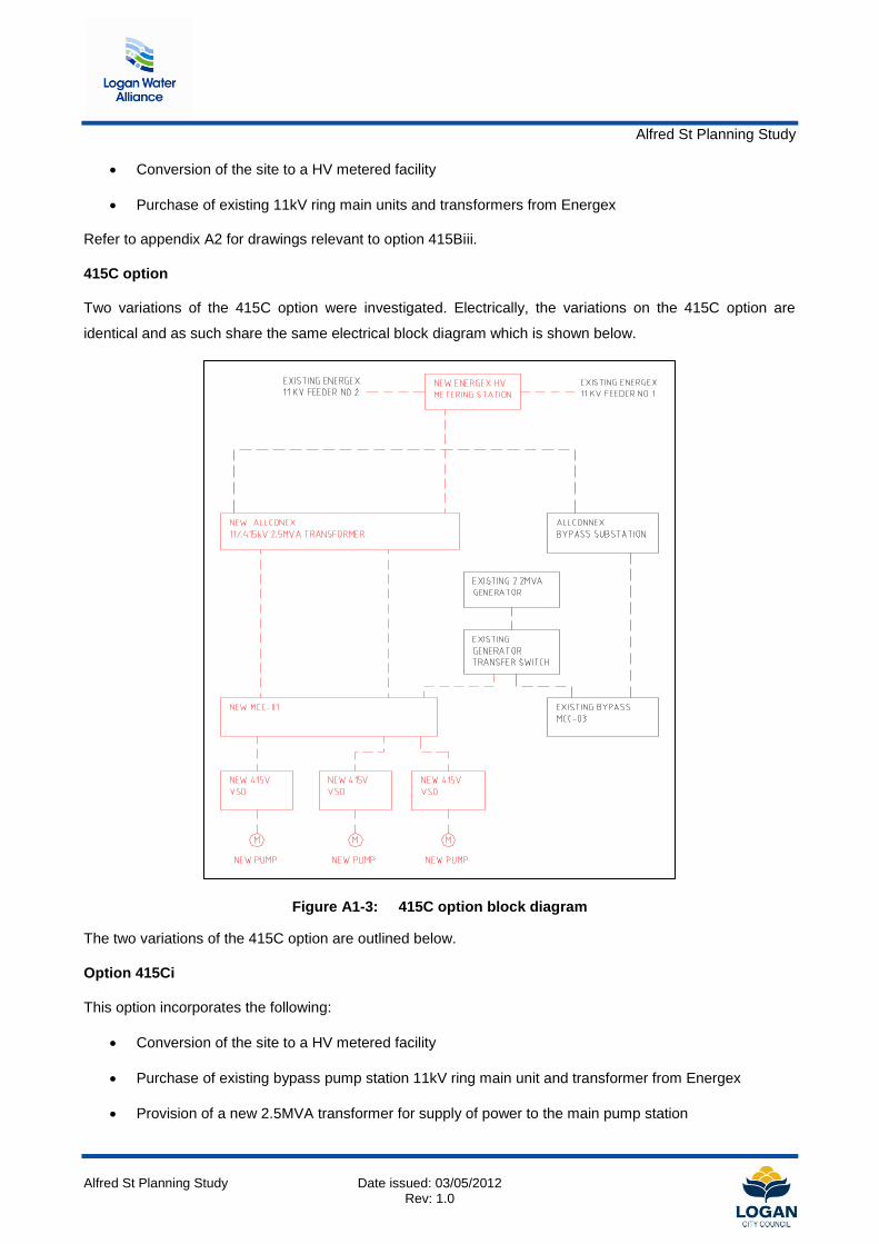
Alfred St Planning Study
Alfred St Planning Study Date issued: 03/05/2012 Rev: 1.0
Conversion of the site to a HV metered facility
Purchase of existing 11kV ring main units and transformers from Energex
Refer to appendix A2 for drawings relevant to option 415Biii.
415C option
Two variations of the 415C option were investigated. Electrically, the variations on the 415C option are
identical and as such share the same electrical block diagram which is shown below.
Figure A1-3: 415C option block diagram
The two variations of the 415C option are outlined below.
Option 415Ci
This option incorporates the following:
Conversion of the site to a HV metered facility
Purchase of existing bypass pump station 11kV ring main unit and transformer from Energex
Provision of a new 2.5MVA transformer for supply of power to the main pump station

Alfred St Planning Study
Alfred St Planning Study Date issued: 03/05/2012 Rev: 1.0
Existing generator and associated manual transfer switch are retained
Existing switchboards are removed
Existing variable speed drive and motor number 3 are assumed to be retained and reused
The existing switch room walls are sealed to the underside off the roof or ceiling installed in
conjunction with mechanical ventilation to reduce the likely hood of moisture or H2S gases affecting
the new switchboards
Provision of new entry and exit doors
Provision of new switchboards, 2 off top entry variable speed drives and 2 off motors
While this option is viable, the space between the variable speed drives restricts the maintenance to one
drive at a time.
Refer to appendix A2 for drawings relevant to option 415Ci.
Option 415Cii
This option incorporates the following:
Conversion of the site to a HV metered facility
Purchase of existing bypass pump station 11kV ring main unit and transformer from Energex
Provision of a new 2.5MVA transformer for supply of power to the main pump station
Existing generator and associated manual transfer switch are retained
Existing switchboards are removed
Existing variable speed drive and motor number 3 are assumed to be retained and reused
The existing switch room walls are sealed to the underside off the roof or ceiling installed in
conjunction with mechanical ventilation to reduce the likely hood of moisture or H2S gases affecting
the new switchboards
Provision of new entry and exit doors
Provision of new switchboards , 2 off top entry variable speed drives and 2 off
Provision of a raised computer floor to allow bottom entry cabling for the variable speed drives
Refer to appendix A2 for drawings relevant to option 415Cii.
690V Electrical Upgrade options
The investigation into 690V options was discounted early for the following reasons:
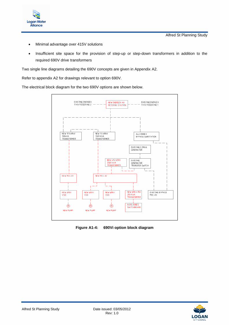
Alfred St Planning Study
Alfred St Planning Study Date issued: 03/05/2012 Rev: 1.0
Minimal advantage over 415V solutions
Insufficient site space for the provision of step-up or step-down transformers in addition to the
required 690V drive transformers
Two single line diagrams detailing the 690V concepts are given in Appendix A2.
Refer to appendix A2 for drawings relevant to option 690V.
The electrical block diagram for the two 690V options are shown below.
Figure A1-4: 690Vi option block diagram

Alfred St Planning Study
Alfred St Planning Study Date issued: 03/05/2012 Rev: 1.0
Figure A1-5: 690Vii option block diagram
3300V Electrical Upgrade options
The investigation into 3300V options was broken down into three basic categories:
No generator backup for the main pump station
Generator back up via a step-up transformer for the main pump station
11kV generator standby supply
Refer to appendix A2 for drawings relevant to option 3300V.
The three variations of the 3300V option are outlined below.

Alfred St Planning Study
Alfred St Planning Study Date issued: 03/05/2012 Rev: 1.0
Option 3300A
This option incorporates the following:
Conversion of the site to a HV metered facility
Purchase of existing bypass pump station 11kV ring main unit and transformer from Energex
Existing generator and associated manual transfer switch are retained
Existing switchboards are removed
Provision of new switchboards and bottom entry variable speed drives
Provision of a new purpose built transportable switch room
Refer to appendix A2 for drawings relevant to option 3300A. The electrical block diagram for the 3300A
option is shown below.
Figure A1-6: 3300A option block diagram
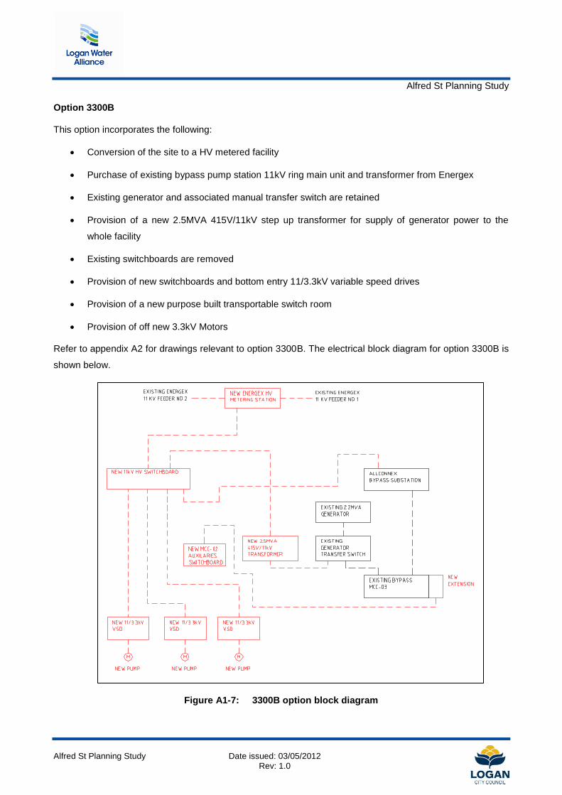
Alfred St Planning Study
Alfred St Planning Study Date issued: 03/05/2012 Rev: 1.0
Option 3300B
This option incorporates the following:
Conversion of the site to a HV metered facility
Purchase of existing bypass pump station 11kV ring main unit and transformer from Energex
Existing generator and associated manual transfer switch are retained
Provision of a new 2.5MVA 415V/11kV step up transformer for supply of generator power to the
whole facility
Existing switchboards are removed
Provision of new switchboards and bottom entry 11/3.3kV variable speed drives
Provision of a new purpose built transportable switch room
Provision of off new 3.3kV Motors
Refer to appendix A2 for drawings relevant to option 3300B. The electrical block diagram for option 3300B is
shown below.
Figure A1-7: 3300B option block diagram

Alfred St Planning Study
Alfred St Planning Study Date issued: 03/05/2012 Rev: 1.0
Option 3300Ci
This option incorporates the following:
Conversion of the site to a HV metered facility
Purchase of existing bypass pump station 11kV ring main unit and transformer from Energex
Existing generator and associated manual transfer switch are removed
Provision of a new 2.25MVA 11kV standby generator
Existing switchboards are removed
Provision of new switchboards and bottom entry 11/3.3kV variable speed drives
Provision of a new purpose built transportable switch room
Provision of off new 3.3kV Motors
Refer to appendix A2 for drawings relevant to option 3300Ci. The electrical block diagram for option 3300Ci
is shown below.
Figure A1-8: 3300Ci option block diagram
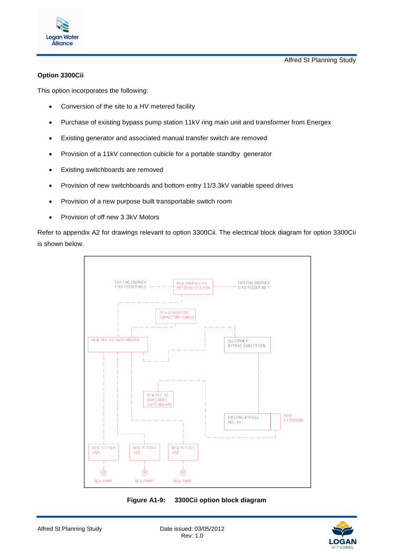
Alfred St Planning Study
Alfred St Planning Study Date issued: 03/05/2012 Rev: 1.0
Option 3300Cii
This option incorporates the following:
Conversion of the site to a HV metered facility
Purchase of existing bypass pump station 11kV ring main unit and transformer from Energex
Existing generator and associated manual transfer switch are removed
Provision of a 11kV connection cubicle for a portable standby generator
Existing switchboards are removed
Provision of new switchboards and bottom entry 11/3.3kV variable speed drives
Provision of a new purpose built transportable switch room
Provision of off new 3.3kV Motors
Refer to appendix A2 for drawings relevant to option 3300Cii. The electrical block diagram for option 3300Cii
is shown below.
Figure A1-9: 3300Cii option block diagram
Alfred St Planning Study
Alfred St Planning Study Date issued: 03/05/2012 Rev: 1.0
Appendix A-2 Electrical options assessment drawings

PRELIMINARY

PRELIMINARY
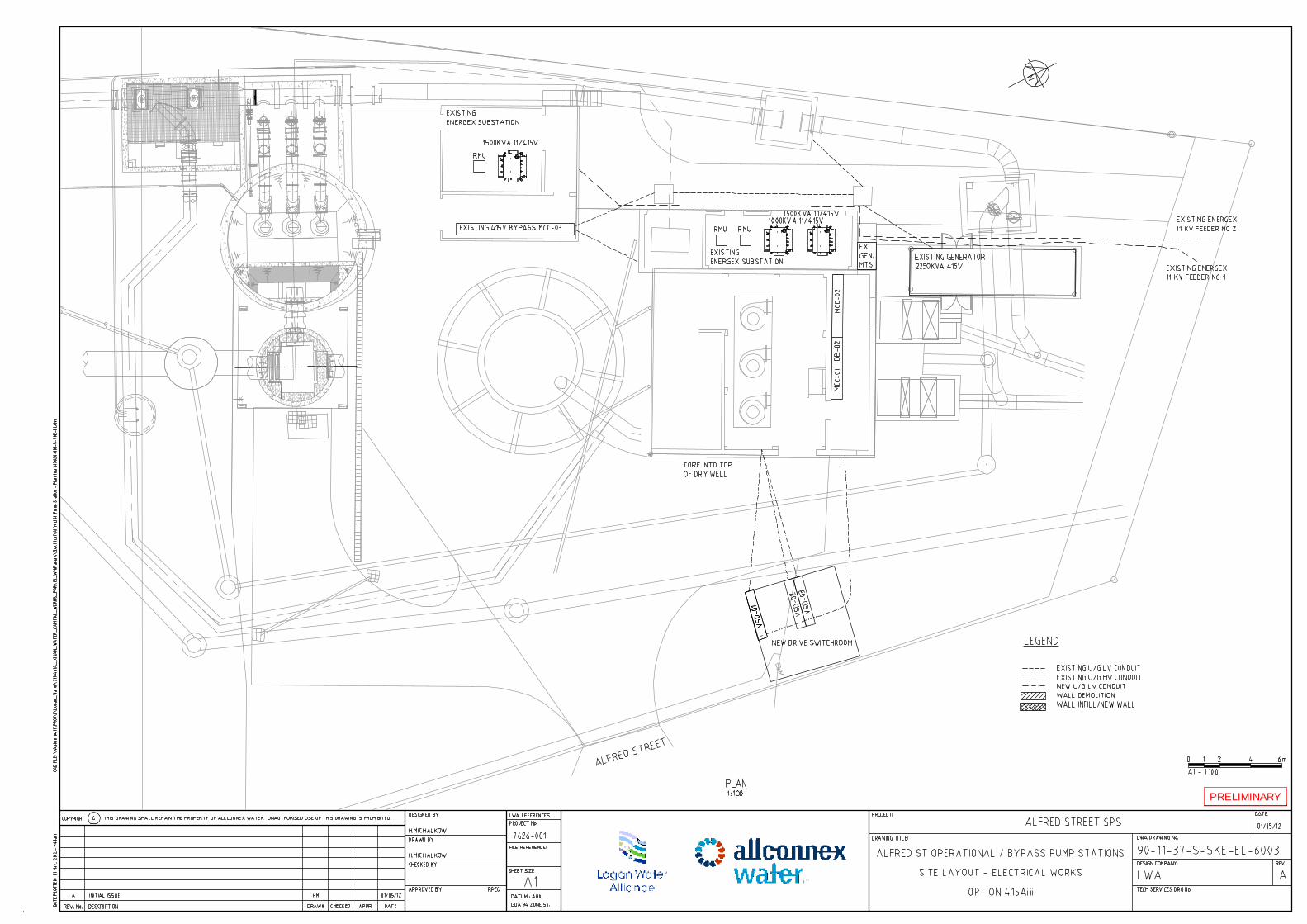
PRELIMINARY

PRELIMINARY

PRELIMINARY

PRELIMINARY

PRELIMINARY

PRELIMINARY

PRELIMINARY

PRELIMINARY
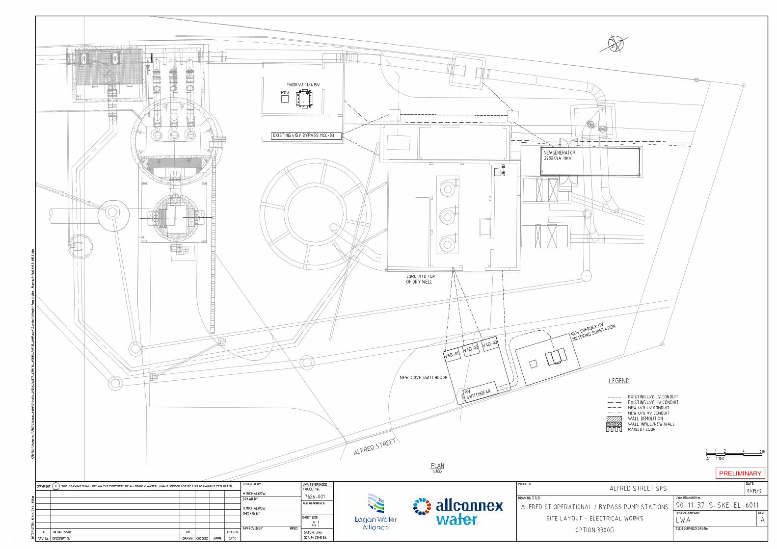
PRELIMINARY

PRELIMINARY

PRELIMINARY

PRELIMINARY

PRELIMINARY

PRELIMINARY

PRELIMINARY

PRELIMINARY

PRELIMINARY
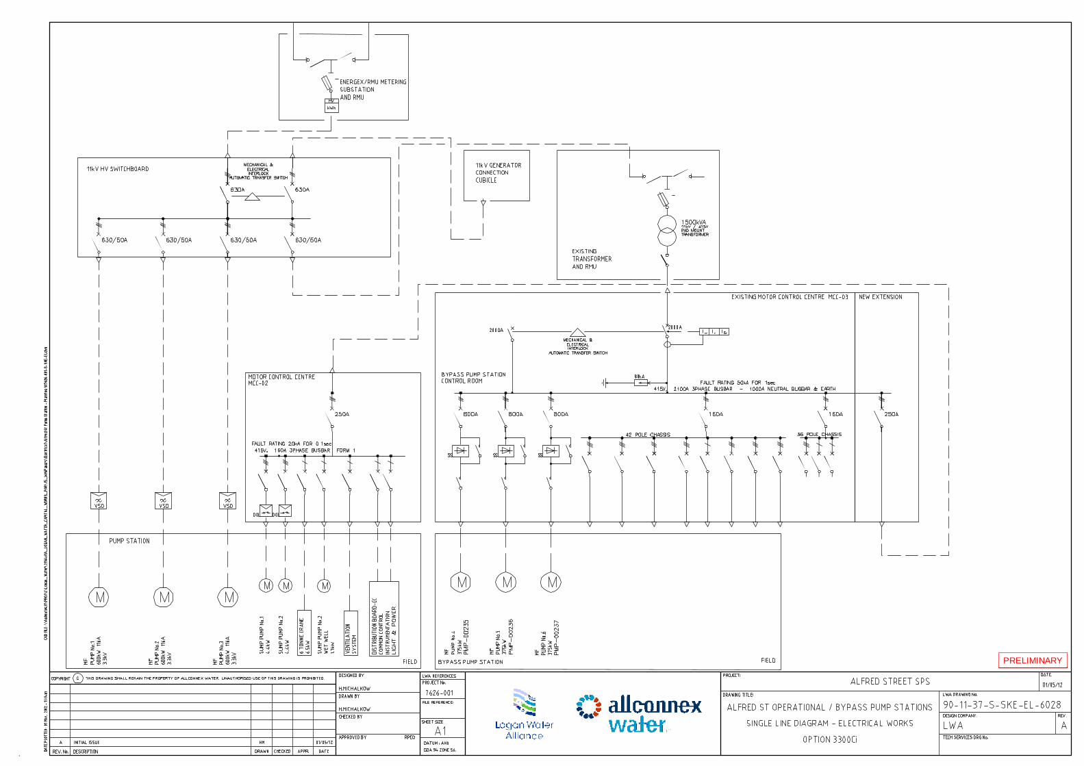
PRELIMINARY

PRELIMINARY
Alfred St Planning Study
Alfred St Planning Study Date issued: 03/05/2012 Rev: 1.0
Appendix A-3 Electrical options study cost estimates

Option 415Ai 415V LV metering
Item No. Description Unit Quantity Rate Amount Total1 .1 .0 Energex works
.1 .1
.1 .2
.1 .31 .2 .1
.2 .2 600kW 415V each 3 $105,000 315,000$
.2 .3 Deliver and install the above equipment lot 1 10% 31,500$ 346,500$ 1 .3 .0
.3 .1 2500A breaker each 3 $20,000 60,000$
.3 .2 Deliver and install the above equipment lot 1 20% 12,000$
.3 .3 Auto transfer with interlocks each 1 $10,000 10,000$
.3 .4 Deliver and install the above equipment lot 1 20% 2,000$
.3 .5 1250A breaker each 2 $15,000 30,000$
.3 .6 Deliver and install the above equipment lot 1 20% 6,000$
.3 .7 250A breaker each 1 $2,000 2,000$
.3 .8 Deliver and install the above equipment lot 1 20% 400$
.3 .9 Panel work/busbars m² 9 $2,500 22,500$ 144,900$ 1 .4 .1
.4 .1 36 pole db each 1 $5,000 5,000$
.4 .2 Deliver and install the above equipment lot 1 20% 1,000$ 6,000$ 4
1 .5 .0.5 .1 1250A breaker each 2 $15,000 30,000$ .5 .2 Deliver and install the above equipment lot 1 20% 6,000$ .5 .3 Panel work/busbars m² 5 $2,500 12,500$ 48,500$
1 .5 .1.5 .2 MCC 01 feeder 4/Ø 400mm² lot 10 $400 4,000$ .5 .3 MCC 02 feeder 5/Ø 400mm² lot 10 $500 5,000$ .5 .4 VSD-01 feeder 3/Ø 400mm² lot 12 $300 3,600$ .5 .5 VSD-02 feeder 3/Ø 400mm² lot 8 $300 2,400$ .5 .6 VSD-03 feeder 3/Ø 400mm² lot 10 $300 3,000$ .5 .7 Generator feeder 5/Ø 400mm² lot 8 $500 4,000$ .5 .8 MTR-01 feeder 415V lot 10 $300 3,000$ .5 .9 MTR-02 feeder 415V lot 15 $300 4,500$ .5 .10 MTR-03 feeder 415V lot 20 $300 6,000$ 35,500$
1 .6 .1 /m 12 $500 6,000$ 6,000$ 1 .7 .1 /m 12 $2,000 24,000$ 24,000$ 1 .8 .1 /m 6 $400 2,400$ 2,400$ 1 .9 .1 /m 8 $1,500 12,000$ 12,000$ 1 .10 .1 /m 1 $35,000 35,000$ 35,000$ 1 .11 .1
.11 .1 600kW each 3 $70,000 210,000$
.11 .2 Deliver and install the above equipment lot 1 20% 42,000$ 252,000$
SUBTOTAL $912,800
*Assumes No motor or VSD are retained
VSD*
MCC02
DB02
LV cables
Motors*
Sealing of roomDemolition of old board/cables
Demolition of old wallBuilding of new wall
MCC01
Ventillation allowance

Option 415Aii 415V LV metering
Item No. Description Unit Quantity Rate Amount Total1 .1 .0 Energex works
.1 .1
.1 .2
.1 .31 .2 .1
.2 .2 600kW 415V each 3 $100,000 300,000$
.2 .3 Deliver and install the above equipment lot 1 10% 30,000$ 330,000$ 1 .3 .0
.3 .1 2500A breaker each 3 $20,000 60,000$
.3 .2 Deliver and install the above equipment lot 1 20% 12,000$
.3 .3 Auto transfer with interlocks each 1 $10,000 10,000$
.3 .4 Deliver and install the above equipment lot 1 20% 2,000$
.3 .5 1250A breaker each 2 $15,000 30,000$
.3 .6 Deliver and install the above equipment lot 1 20% 6,000$
.3 .7 250A breaker each 1 $2,000 2,000$
.3 .8 Deliver and install the above equipment lot 1 20% 400$
.3 .9 Panel work/busbars m² 9 $2,500 22,500$ 144,900$ 1 .4 .1
.4 .1 36 pole db each 1 $5,000 5,000$
.4 .2 Deliver and install the above equipment lot 1 20% 1,000$ 6,000$ 4
1 .5 .0.5 .1 1250A breaker each 2 $15,000 30,000$ .5 .2 Deliver and install the above equipment lot 1 20% 6,000$ .5 .3 Panel work/busbars m² 5 $2,500 12,500$ 48,500$
1 .5 .1.5 .2 MCC 01 feeder 4/Ø 400mm² lot 10 $400 4,000$ .5 .3 MCC 02 feeder 5/Ø 400mm² lot 10 $500 5,000$ .5 .4 VSD-01 feeder 3/Ø 400mm² lot 7.5 $300 2,250$ .5 .5 VSD-02 feeder 3/Ø 400mm² lot 10 $300 3,000$ .5 .6 VSD-03 feeder 3/Ø 400mm² lot 12.5 $300 3,750$ .5 .7 Generator feeder 5/Ø 400mm² lot 8 $500 4,000$ .5 .8 MTR-01 feeder 415V lot 15 $300 4,500$ .5 .9 MTR-02 feeder 415V lot 15 $300 4,500$ .5 .10 MTR-03 feeder 415V lot 15 $300 4,500$ 35,500$ 5
1 .6 .1 /m 12 $500 6,000$ 6,000$ 1 .7 .1 /m 12 $2,000 24,000$ 24,000$ 1 .8 .1 /m 6 $400 2,400$ 2,400$ 1 .9 .1 /m 8 $1,500 12,000$ 12,000$ 1 .10 .1 /m 24 $1,000 24,000$ 24,000$ 1 .11 .1 /m 1 $35,000 35,000$ 35,000$ 1 .12 .1
.12 .1 600kW each 3 $70,000 210,000$
.12 .2 Deliver and install the above equipment lot 1 20% 42,000$ 252,000$
SUBTOTAL $920,300
*Assumes No motor or VSD are retained
Motors*
VSD*
MCC02
DB02
MCC01
LV cables
Demolition of old board/cablesSealing of roomDemolition of old wallBuilding of new wallRaised floorVentillation allowance

Option 415Aiii 415V LV metering
Item No. Description Unit Quantity Rate Amount Total1 .1 .0 Energex works
.1 .1
.1 .2
.1 .31 .2 .1
.2 .2 600kW 415V each 3 $100,000 300,000$
.2 .3 Deliver and install the above equipment lot 1 10% 30,000$ 330,000$ 1 .3 .0
.3 .1 2500A breaker each 3 $20,000 60,000$
.3 .2 Deliver and install the above equipment lot 1 20% 12,000$
.3 .3 Auto transfer with interlocks each 1 $10,000 10,000$
.3 .4 Deliver and install the above equipment lot 1 20% 2,000$
.3 .5 1250A breaker each 2 $15,000 30,000$
.3 .6 Deliver and install the above equipment lot 1 20% 6,000$
.3 .7 250A breaker each 1 $2,000 2,000$
.3 .8 Deliver and install the above equipment lot 1 20% 400$
.3 .9 Panel work/busbars m² 9 $2,500 22,500$ 144,900$ 1 .4 .1
.4 .1 36 pole db each 1 $5,000 5,000$
.4 .2 Deliver and install the above equipment lot 1 20% 1,000$ 6,000$ 4
1 .5 .0.5 .1 1250A breaker each 2 $15,000 30,000$ .5 .2 Deliver and install the above equipment lot 1 20% 6,000$ .5 .3 Panel work/busbars m² 5 $2,500 12,500$ 48,500$
1 .5 .1.5 .2 MCC 01 feeder 4/Ø 400mm² lot 20 $400 8,000$ .5 .3 MCC 02 feeder 5/Ø 400mm² lot 10 $500 5,000$ .5 .4 VSD-01 feeder 4/Ø 400mm² lot 30 $400 12,000$ .5 .5 VSD-02 feeder 4/Ø 400mm² lot 37.5 $400 15,000$ .5 .6 VSD-03 feeder 4/Ø 400mm² lot 37.5 $400 15,000$ .5 .7 Generator feeder 5/Ø 400mm² lot 8 $500 4,000$ .5 .8 MTR-01 feeder 415V lot 25 $300 7,500$ .5 .9 MTR-02 feeder 415V lot 30 $300 9,000$ .5 .10 MTR-03 feeder 415V lot 35 $300 10,500$ 86,000$
1 .6 .1 /m 350 $50 17,500$ 17,500$ 1 .6 .1 /m 12 $2,000 24,000$ 24,000$ 1 .6 .1 /m² 36 $4,000 144,000$ 144,000$ 1 .7 .1
.7 .1 600kW each 3 $70,000 210,000$
.7 .2 Deliver and install the above equipment lot 1 20% 42,000$ 252,000$
SUBTOTAL $1,052,900
*Assumes No motor or VSD are retained
Demountable switchrooomSealing of roomu/g conduits
VSD*
MCC02
DB02
MCC01
LV cables
Motors*

Option 415Bi 415V HV metering
Item No. Description Unit Quantity Rate Amount Total1 .1 .0 Energex works
.1 .1 RMU metering substation each 1 $112,000 112,000$
.1 .2 Substation civil section each 1 $25,000 25,000$
.1 .3 11kV cable /m 1 $25,000 25,000$
.1 .4 Residual value of existing Energex equipment /m 6 $10,000 60,000$ 222,000$
1 .2 .1 /m 125 $500 62,500$ 62,500$
1 .3 .1 VSD*.3 .2 600kW 415V each 3 $105,000 315,000$ .3 .3 Deliver and install the above equipment lot 1 10% 31,500$ 346,500$
1 .4 .0.4 .1 2500A breaker each 3 $20,000 60,000$ .4 .2 Deliver and install the above equipment lot 1 20% 12,000$ .4 .3 Auto transfer with interlocks each 1 $10,000 10,000$ .4 .4 Deliver and install the above equipment lot 1 20% 2,000$ .4 .5 1250A breaker each 2 $15,000 30,000$ .4 .6 Deliver and install the above equipment lot 1 20% 6,000$ .4 .7 250A breaker each 1 $2,000 2,000$ .4 .8 Deliver and install the above equipment lot 1 20% 400$ .4 .9 Panel work/busbars m² 9 $2,500 22,500$ 144,900$
1 .5 .1.5 .1 36 pole db each 1 $5,000 5,000$ .5 .2 Deliver and install the above equipment lot 1 20% 1,000$ 6,000$ 5
1 .6 .0.6 .1 1250A breaker each 2 $15,000 30,000$ .6 .2 Deliver and install the above equipment lot 1 20% 6,000$ .6 .3 Panel work/busbars m² 5 $2,500 12,500$ 48,500$
1 .6 .1.6 .2 MCC 01 feeder 4/Ø 400mm² lot 10 $400 4,000$ .6 .3 MCC 02 feeder 5/Ø 400mm² lot 10 $500 5,000$ .6 .4 VSD-01 feeder 3/Ø 400mm² lot 12 $300 3,600$ .6 .5 VSD-02 feeder 3/Ø 400mm² lot 8 $300 2,400$ .6 .6 VSD-03 feeder 3/Ø 400mm² lot 10 $300 3,000$ .6 .7 Generator feeder 5/Ø 400mm² lot 8 $500 4,000$ .6 .8 MTR-01 feeder 415V lot 10 $300 3,000$ .6 .9 MTR-02 feeder 415V lot 15 $300 4,500$ .6 .10 MTR-03 feeder 415V lot 20 $300 6,000$ 35,500$
1 .7 .1 /m 12 $500 6,000$ 6,000$ 1 .8 .1 /m 12 $2,000 24,000$ 24,000$ 1 .9 .1 /m 6 $400 2,400$ 2,400$ 1 .10 .1 /m 8 $1,500 12,000$ 12,000$ 1 .11 .1 /m 1 $35,000 35,000$ 35,000$ 1 .12 .1
.12 .1 600kW each 3 $70,000 210,000$
.12 .2 Deliver and install the above equipment lot 1 20% 42,000$ 252,000$ SUBTOTAL $1,197,300
*Assumes No motor or VSD are retained
Motors*
Sealing of roomDemolition of old wallBuilding of new wall
11kV cable
MCC02
DB02
MCC01
LV cables
Demolition of old board/cables
Ventillation allowance

Option 415Bii 415V HV metering
Description Unit Quantity Rate Amount Total1 .1 .0 Energex works
.1 .1 RMU metering substation each 1 $112,000 112,000$
.1 .2 Substation civil section each 1 $25,000 25,000$
.1 .3 11kV cable /m 1 $25,000 25,000$
.1 .4 Residual value of existing Energex equipment /m 6 $10,000 60,000$ 222,000$
1 .2 .1 /m 125 $500 62,500$ 62,500$
1 .2 .1.2 .2 600kW 415V each 3 $100,000 300,000$ .2 .3 Deliver and install the above equipment lot 1 10% 30,000$ 330,000$
1 .3 .0.3 .1 2500A breaker each 3 $20,000 60,000$ .3 .2 Deliver and install the above equipment lot 1 20% 12,000$ .3 .3 Auto transfer with interlocks each 1 $10,000 10,000$ .3 .4 Deliver and install the above equipment lot 1 20% 2,000$ .3 .5 1250A breaker each 2 $15,000 30,000$ .3 .6 Deliver and install the above equipment lot 1 20% 6,000$ .3 .7 250A breaker each 1 $2,000 2,000$ .3 .8 Deliver and install the above equipment lot 1 20% 400$ .3 .9 Panel work/busbars m² 9 $2,500 22,500$ 144,900$
1 .4 .1.4 .1 36 pole db each 1 $5,000 5,000$ .4 .2 Deliver and install the above equipment lot 1 20% 1,000$ 6,000$ 4
1 .5 .0.5 .1 1250A breaker each 2 $15,000 30,000$ .5 .2 Deliver and install the above equipment lot 1 20% 6,000$ .5 .3 Panel work/busbars m² 5 $2,500 12,500$ 48,500$
1 .5 .1.5 .2 MCC 01 feeder 4/Ø 400mm² lot 10 $400 4,000$ .5 .3 MCC 02 feeder 5/Ø 400mm² lot 10 $500 5,000$ .5 .4 VSD-01 feeder 3/Ø 400mm² lot 7.5 $300 2,250$ .5 .5 VSD-02 feeder 3/Ø 400mm² lot 10 $300 3,000$ .5 .6 VSD-03 feeder 3/Ø 400mm² lot 12.5 $300 3,750$ .5 .7 Generator feeder 5/Ø 400mm² lot 8 $500 4,000$ .5 .8 MTR-01 feeder 415V lot 15 $300 4,500$ .5 .9 MTR-02 feeder 415V lot 15 $300 4,500$ .5 .10 MTR-03 feeder 415V lot 15 $300 4,500$ 35,500$ 55
1 .6 .1 /m 12 $500 6,000$ 6,000$ 1 .7 .1 /m 12 $2,000 24,000$ 24,000$ 1 .8 .1 /m 6 $400 2,400$ 2,400$ 1 .9 .1 /m 8 $1,500 12,000$ 12,000$ 1 .10 .1 /m 24 $1,000 24,000$ 24,000$ 1 .11 .1 /m 1 $35,000 35,000$ 35,000$ 1 .12 .1
.12 .1 600kW each 3 $70,000 210,000$
.12 .2 Deliver and install the above equipment lot 1 20% 42,000$ 252,000$
SUBTOTAL $1,204,800
Demolition of old wall
Motors*
Building of new wallRaised floor
VSD*
MCC02
DB02
MCC01
LV cables
Ventillation allowance
Item No.
11kV cable
Demolition of old board/cablesSealing of room

Option 415Biii 415V HV metering
Item No. Description Unit Quantity Rate Amount Total1 .1 .0 Energex works
.1 .1 RMU metering substation each 1 $112,000 112,000$
.1 .2 Substation civil section each 1 $25,000 25,000$
.1 .3 11kV cable /m 1 $25,000 25,000$
.1 .4 Residual value of existing Energex equipment /m 6 $10,000 60,000$ 222,000$
1 .1 .1 /m 125 $500 62,500$ 62,500$
1 .2 .1.2 .2 600kW 415V each 3 $100,000 300,000$ .2 .3 Deliver and install the above equipment lot 1 10% 30,000$ 330,000$
1 .3 .0.3 .1 2500A breaker each 3 $20,000 60,000$ .3 .2 Deliver and install the above equipment lot 1 20% 12,000$ .3 .3 Auto transfer with interlocks each 1 $10,000 10,000$ .3 .4 Deliver and install the above equipment lot 1 20% 2,000$ .3 .5 1250A breaker each 2 $15,000 30,000$ .3 .6 Deliver and install the above equipment lot 1 20% 6,000$ .3 .7 250A breaker each 1 $2,000 2,000$ .3 .8 Deliver and install the above equipment lot 1 20% 400$ .3 .9 Panel work/busbars m² 9 $2,500 22,500$ 144,900$
1 .4 .1.4 .1 36 pole db each 1 $5,000 5,000$ .4 .2 Deliver and install the above equipment lot 1 20% 1,000$ 6,000$ 4
1 .5 .0.5 .1 1250A breaker each 2 $15,000 30,000$ .5 .2 Deliver and install the above equipment lot 1 20% 6,000$ .5 .3 Panel work/busbars m² 5 $2,500 12,500$ 48,500$
1 .5 .1.5 .2 MCC 01 feeder 4/Ø 400mm² lot 20 $400 8,000$ .5 .3 MCC 02 feeder 5/Ø 400mm² lot 10 $500 5,000$ .5 .4 VSD-01 feeder 4/Ø 400mm² lot 30 $400 12,000$ .5 .5 VSD-02 feeder 4/Ø 400mm² lot 37.5 $400 15,000$ .5 .6 VSD-03 feeder 4/Ø 400mm² lot 37.5 $400 15,000$ .5 .7 Generator feeder 5/Ø 400mm² lot 8 $500 4,000$ .5 .8 MTR-01 feeder 415V lot 25 $300 7,500$ .5 .9 MTR-02 feeder 415V lot 30 $300 9,000$ .5 .10 MTR-03 feeder 415V lot 35 $300 10,500$ 86,000$
1 .6 .1 /m 350 $50 17,500$ 17,500$ 1 .6 .1 /m 12 $2,000 24,000$ 24,000$ 1 .6 .1 /m² 36 $4,000 144,000$ 144,000$ 1 .7 .1
.7 .1 600kW each 3 $70,000 210,000$
.7 .2 Deliver and install the above equipment lot 1 20% 42,000$ 252,000$
SUBTOTAL $1,337,400
*Assumes No motor or VSD are retained
Sealing of roomDemountable switchrooom
11kV cable
VSD*
MCC02
DB02
MCC01
LV cables
u/g conduits
Motors*
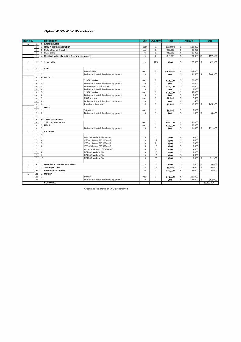
Option 415Ci 415V HV metering
Item No. Description Unit Quantity Rate Amount Total1 .1 .0 Energex works
.1 .1 RMU metering substation each 1 $112,000 112,000$
.1 .2 Substation civil section each 1 $25,000 25,000$
.1 .3 11kV cable /m 1 $25,000 25,000$
.1 .4 Residual value of existing Energex equipment /m 2 $15,000 30,000$ 192,000$
1 .2 .1 /m 125 $500 62,500$ 62,500$
1 .3 .1 VSD*.3 .2 600kW 415V each 3 $105,000 315,000$ .3 .3 Deliver and install the above equipment lot 1 10% 31,500$ 346,500$
1 .4 .0.4 .1 3200A breaker each 2 $25,000 50,000$ .4 .2 Deliver and install the above equipment lot 1 20% 10,000$ .4 .3 Auto transfer with interlocks each 1 $10,000 10,000$ .4 .4 Deliver and install the above equipment lot 1 20% 2,000$ .4 .5 1250A breaker each 3 $15,000 45,000$ .4 .6 Deliver and install the above equipment lot 1 20% 9,000$ .4 .7 250A breaker each 1 $2,000 2,000$ .4 .8 Deliver and install the above equipment lot 1 20% 400$ .4 .9 Panel work/busbars m² 7 $2,500 17,500$ 145,900$
1 .5 .1.5 .1 36 pole db each 1 $5,000 5,000$ .5 .2 Deliver and install the above equipment lot 1 20% 1,000$ 6,000$ 5
1 .6 .0.6 .1 2.5MVA transformer each 1 $90,000 90,000$ .6 .2 RMU each 1 $20,000 20,000$ .6 .3 Deliver and install the above equipment lot 1 10% 11,000$ 121,000$
1 .7 .1.7 .2.7 .3 MCC 02 feeder 5/Ø 400mm² lot 10 $500 5,000$ .7 .4 VSD-01 feeder 3/Ø 400mm² lot 12 $300 3,600$ .7 .5 VSD-02 feeder 3/Ø 400mm² lot 8 $300 2,400$ .7 .6 VSD-03 feeder 3/Ø 400mm² lot 10 $300 3,000$ .7 .7 Generator feeder 5/Ø 400mm² lot 8 $500 4,000$ .7 .8 MTR-01 feeder 415V lot 10 $300 3,000$ .7 .9 MTR-02 feeder 415V lot 15 $300 4,500$ .7 .10 MTR-03 feeder 415V lot 20 $300 6,000$ 31,500$
1 .8 .1 /m 12 $500 6,000$ 6,000$ 1 .9 .1 /m 12 $2,000 24,000$ 24,000$ 1 .10 .1 /m 1 $35,000 35,000$ 35,000$ 1 .11 .1
.11 .1 600kW each 3 $70,000 210,000$
.11 .2 Deliver and install the above equipment lot 1 20% 42,000$ 252,000$ SUBTOTAL $1,222,400
*Assumes No motor or VSD are retained
Motors*
Sealing of room
11kV cable
MCC02
DB02
2.5MVA substation
LV cables
Demolition of old board/cables
Ventillation allowance

Option 415Cii 415V HV metering
Item No. Description Unit Quantity Rate Amount Total1 .1 .0 Energex works
.1 .1 RMU metering substation each 1 $112,000 112,000$
.1 .2 Substation civil section each 1 $25,000 25,000$
.1 .3 11kV cable /m 1 $25,000 25,000$
.1 .4 Residual value of existing Energex equipment /m 6 $10,000 60,000$ 222,000$
1 .2 .1 /m 125 $500 62,500$ 62,500$
1 .2 .1.2 .2 600kW 415V each 3 $100,000 300,000$ .2 .3 Deliver and install the above equipment lot 1 10% 30,000$ 330,000$
1 .3 .0.3 .1 3200A breaker each 2 $25,000 50,000$ .3 .2 Deliver and install the above equipment lot 1 20% 10,000$ .3 .3 Auto transfer with interlocks each 1 $10,000 10,000$ .3 .4 Deliver and install the above equipment lot 1 20% 2,000$ .3 .5 1250A breaker each 3 $15,000 45,000$ .3 .6 Deliver and install the above equipment lot 1 20% 9,000$ .3 .7 250A breaker each 1 $2,000 2,000$ .3 .8 Deliver and install the above equipment lot 1 20% 400$ .3 .9 Panel work/busbars m² 7 $2,500 17,500$ 145,900$
1 .4 .1.4 .1 36 pole db each 1 $5,000 5,000$ .4 .2 Deliver and install the above equipment lot 1 20% 1,000$ 6,000$ 4
1 .5 .0.5 .1 2.5MVA transformer each 1 $90,000 90,000$ .5 .2 RMU each 1 $20,000 20,000$ .5 .3 Deliver and install the above equipment lot 1 10% 11,000$ 121,000$
1 .6 .1.6 .2.6 .3 MCC 02 feeder 5/Ø 400mm² lot 10 $500 5,000$ .6 .4 VSD-01 feeder 3/Ø 400mm² lot 7.5 $300 2,250$ .6 .5 VSD-02 feeder 3/Ø 400mm² lot 10 $300 3,000$ .6 .6 VSD-03 feeder 3/Ø 400mm² lot 12.5 $300 3,750$ .6 .7 Generator feeder 5/Ø 400mm² lot 8 $500 4,000$ .6 .8 MTR-01 feeder 415V lot 15 $300 4,500$ .6 .9 MTR-02 feeder 415V lot 15 $300 4,500$ .6 .10 MTR-03 feeder 415V lot 15 $300 4,500$ 31,500$ 66
1 .7 .1 /m 12 $500 6,000$ 6,000$ 1 .8 .1 /m 12 $2,000 24,000$ 24,000$ 1 .9 .1 /m 24 $1,000 24,000$ 24,000$ 1 .10 .1 /m 1 $35,000 35,000$ 35,000$ 1 .11 .1
.11 .1 600kW each 3 $70,000 210,000$
.11 .2 Deliver and install the above equipment lot 1 20% 42,000$ 252,000$
SUBTOTAL $1,259,900
*Assumes No motor or VSD are retained
Motors*
Raised floor
11kV cable
VSD*
MCC02
DB02
2.5MVA substation
LV cables
Demolition of old board/cablesSealing of room
Ventillation allowance

Option 3300A HV metering
Description Unit Quantity Rate Amount Total1 .1 .0 Energex works
.1 .1 RMU metering substation each 1 $112,000 112,000$
.1 .2 Substation civil section each 1 $25,000 25,000$
.1 .3 11kV cable /m 1 $25,000 25,000$
.1 .4 Residual value of existing Energex equipment /m 2 $15,000 30,000$ 192,000$
1 .1 .1 /m 100 $500 50,000$ 50,000$
1 .2 .1.2 .2 600kW 3300V each 3 $200,000 600,000$ .2 .3 Deliver and install the above equipment lot 1 10% 60,000$ 660,000$
1 .3 .0.3 .1 MCC03 extension each 1 $10,000 10,000$ .3 .2 Deliver and install the above equipment lot 1 10% 1,000$ .3 .3 submain DB-02 feeder lot 30 $200 6,000$ 17,000$
1 .4 .1.4 .1 36 pole db each 1 $5,000 5,000$ .4 .2 Deliver and install the above equipment lot 1 20% 1,000$ 6,000$ 4
1 .5 .0.5 .1 630A breaker each 5 $30,000 150,000$ .5 .2 Deliver and install the above equipment lot 1 20% 30,000$ 180,000$ .5 .3
1 .6 .1.6 .2 VSD-01 feeder 11kV lot 10 $400 4,000$ .6 .3 VSD-02 feeder 11kV lot 10 $400 4,000$ .6 .4 VSD-03 feeder 11kV lot 10 $400 4,000$ .6 .5 MTR-01 feeder 3.3kV lot 20 $400 8,000$ .6 .6 MTR-02 feeder 3.3kV lot 25 $400 10,000$ .6 .7 MTR-03 feeder 3.3kV lot 30 $400 12,000$ 42,000$
1 .7 .1 /m 60 $50 3,000$ 3,000$ 1 .8 .1 /m 12 $500 6,000$ 6,000$ 1 .9 .1
.9 .1 600kW each 3 $70,000 210,000$
.9 .2 Deliver and install the above equipment lot 1 20% 42,000$ 252,000$ 1 .10 .1 /m² 36 $4,000 144,000$ 144,000$
SUBTOTAL $1,552,000
Item No.
u/g conduitsDemolition of old board/cables
11kV cable
VSD
Main pumpstation LV supply
DB02
HV switchboard
Cables
Motors*
Demountable switchrooom

Option 3300B HV metering
Item No. Description Unit Quantity Rate Amount Total1 .1 .0 Energex works
.1 .1 RMU metering substation each 1 $112,000 112,000$
.1 .2 Substation civil section each 1 $25,000 25,000$
.1 .3 11kV cable /m 1 $25,000 25,000$
.1 .4 Residual value of existing Energex equipment /m 2 $15,000 30,000$ 192,000$
1 .1 .1 11kV cable (inc 50m for generator transformer) /m 150 $500 75,000$ 75,000$
1 .2 .1.2 .2 600kW 3300V each 3 $200,000 600,000$ .2 .3 Deliver and install the above equipment lot 1 10% 60,000$ 660,000$
1 .3 .0.3 .1 MCC03 extension each 1 $10,000 10,000$ .3 .2 Deliver and install the above equipment lot 1 10% 1,000$ .3 .3 submain DB-02 feeder lot 30 $200 6,000$ 17,000$
1 .4 .1.4 .1 36 pole db each 1 $5,000 5,000$ .4 .2 Deliver and install the above equipment lot 1 20% 1,000$ 6,000$ 4
1 .5 .0.5 .1 630A breaker each 6 $30,000 180,000$ .5 .2 Deliver and install the above equipment lot 1 20% 36,000$ 216,000$ .5 .3
1 .6 .0.6 .1 2.5MVA transformer each 1 $90,000 90,000$ .6 .2 -$ .6 .3 Deliver and install the above equipment lot 1 10% 9,000$ 99,000$
1 .7 .1.7 .2 VSD-01 feeder 11kV lot 10 $400 4,000$ .7 .3 VSD-02 feeder 11kV lot 10 $400 4,000$ .7 .4 VSD-03 feeder 11kV lot 10 $400 4,000$ .7 .5 MTR-01 feeder 3.3kV lot 20 $400 8,000$ .7 .6 MTR-02 feeder 3.3kV lot 25 $400 10,000$ .7 .7 MTR-03 feeder 3.3kV lot 30 $400 12,000$ .7 .8 Generator feeder 5/Ø 400mm² lot 10 $500 5,000$ 47,000$
1 .8 .1 /m 80 $50 4,000$ 4,000$ 1 .9 .1 /m 12 $500 6,000$ 6,000$ 1 .10 .1
.10 .1 600kW each 3 $70,000 210,000$
.10 .2 Deliver and install the above equipment lot 1 20% 42,000$ 252,000$ 1 .11 .1 /m² 36 $4,000 144,000$ 144,000$
SUBTOTAL $1,718,000
VSD
Main pumpstation LV supply
DB02
HV switchboard
Cables
u/g conduitsDemolition of old board/cables
Demountable switchrooom
2.5MVA substation
Motors*
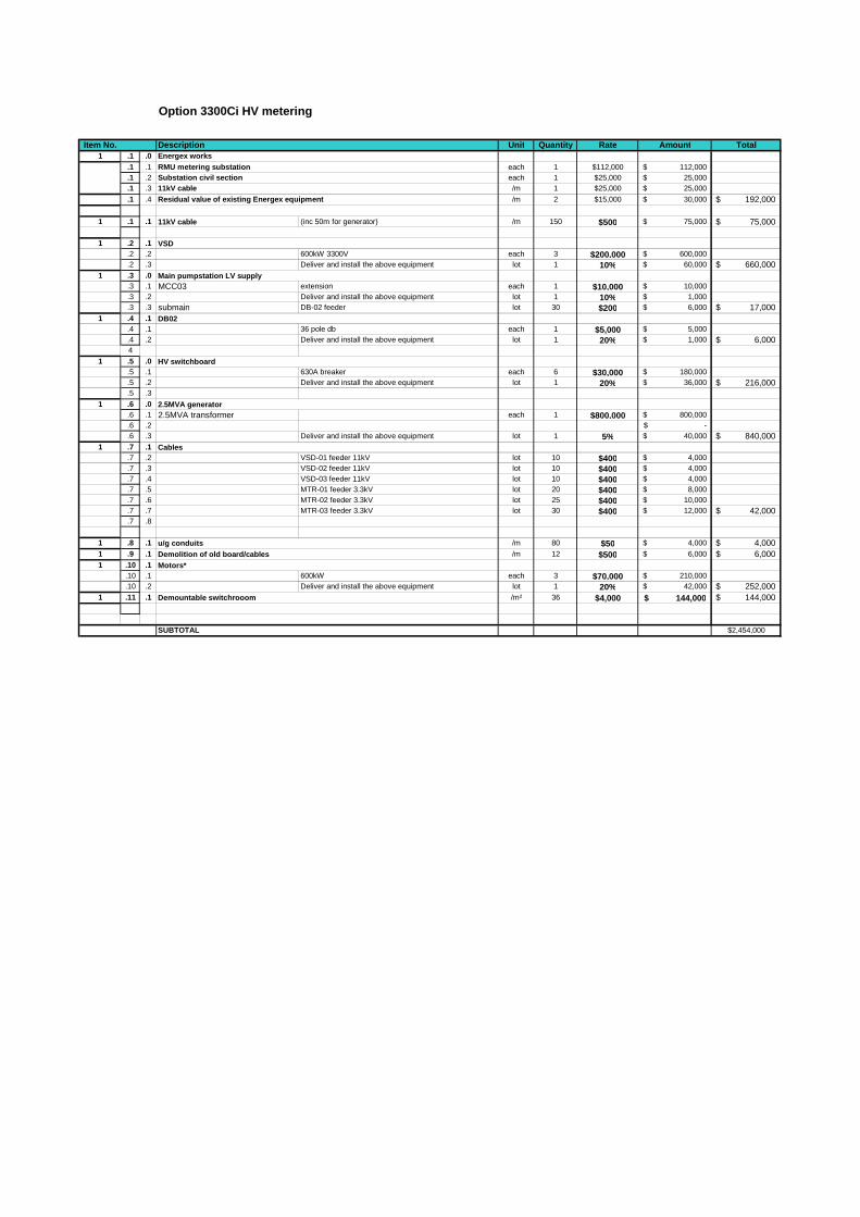
Option 3300Ci HV metering
Item No. Description Unit Quantity Rate Amount Total1 .1 .0 Energex works
.1 .1 RMU metering substation each 1 $112,000 112,000$
.1 .2 Substation civil section each 1 $25,000 25,000$
.1 .3 11kV cable /m 1 $25,000 25,000$
.1 .4 Residual value of existing Energex equipment /m 2 $15,000 30,000$ 192,000$
1 .1 .1 11kV cable (inc 50m for generator) /m 150 $500 75,000$ 75,000$
1 .2 .1.2 .2 600kW 3300V each 3 $200,000 600,000$ .2 .3 Deliver and install the above equipment lot 1 10% 60,000$ 660,000$
1 .3 .0.3 .1 MCC03 extension each 1 $10,000 10,000$ .3 .2 Deliver and install the above equipment lot 1 10% 1,000$ .3 .3 submain DB-02 feeder lot 30 $200 6,000$ 17,000$
1 .4 .1.4 .1 36 pole db each 1 $5,000 5,000$ .4 .2 Deliver and install the above equipment lot 1 20% 1,000$ 6,000$ 4
1 .5 .0.5 .1 630A breaker each 6 $30,000 180,000$ .5 .2 Deliver and install the above equipment lot 1 20% 36,000$ 216,000$ .5 .3
1 .6 .0.6 .1 2.5MVA transformer each 1 $800,000 800,000$ .6 .2 -$ .6 .3 Deliver and install the above equipment lot 1 5% 40,000$ 840,000$
1 .7 .1.7 .2 VSD-01 feeder 11kV lot 10 $400 4,000$ .7 .3 VSD-02 feeder 11kV lot 10 $400 4,000$ .7 .4 VSD-03 feeder 11kV lot 10 $400 4,000$ .7 .5 MTR-01 feeder 3.3kV lot 20 $400 8,000$ .7 .6 MTR-02 feeder 3.3kV lot 25 $400 10,000$ .7 .7 MTR-03 feeder 3.3kV lot 30 $400 12,000$ 42,000$ .7 .8
1 .8 .1 /m 80 $50 4,000$ 4,000$ 1 .9 .1 /m 12 $500 6,000$ 6,000$ 1 .10 .1
.10 .1 600kW each 3 $70,000 210,000$
.10 .2 Deliver and install the above equipment lot 1 20% 42,000$ 252,000$ 1 .11 .1 /m² 36 $4,000 144,000$ 144,000$
SUBTOTAL $2,454,000
u/g conduitsDemolition of old board/cables
VSD
Main pumpstation LV supply
DB02
HV switchboard
2.5MVA generator
Cables
Motors*
Demountable switchrooom

Option 3300Cii mod HV metering
Item No. Description Unit Quantity Rate Amount Total1 .1 .0 Energex works
.1 .1 RMU metering substation each 1 $112,000 112,000$
.1 .2 Substation civil section each 1 $25,000 25,000$
.1 .3 11kV cable /m 1 $25,000 25,000$
.1 .4 Residual value of existing Energex equipment /m 2 $15,000 30,000$ 192,000$
1 .1 .1 11kV cable (inc 50m for generator) /m 175 $500 87,500$ 87,500$
1 .2 .1.2 .2 600kW 3300V each 3 $200,000 600,000$ .2 .3 Deliver and install the above equipment lot 1 10% 60,000$ 660,000$
1 .3 .0.3 .1 MCC03 extension each 1 $10,000 10,000$ .3 .2 Deliver and install the above equipment lot 1 10% 1,000$ .3 .3 submain DB-02 feeder lot 30 $200 6,000$ 17,000$
1 .4 .1.4 .1 36 pole db each 1 $5,000 5,000$ .4 .2 Deliver and install the above equipment lot 1 20% 1,000$ 6,000$ 4 6kVA 2 hour UPS lot 2 $20,000 40,000$ 40,000$
1 .5 .0.5 .1 630A breaker each 6 $30,000 180,000$ .5 .2 Deliver and install the above equipment lot 1 20% 36,000$ 216,000$ .5 .3
1 .6 .0.6 .1.6 .2 400A 11 kV connection box each 1 $30,000 30,000$ .6 .3 Deliver and install the above equipment lot 1 10% 3,000$ 33,000$
1 .7 .1.7 .2 VSD-01 feeder 11kV lot 10 $400 4,000$ .7 .3 VSD-02 feeder 11kV lot 10 $400 4,000$ .7 .4 VSD-03 feeder 11kV lot 10 $400 4,000$ .7 .5 MTR-01 feeder 3.3kV lot 20 $400 8,000$ .7 .6 MTR-02 feeder 3.3kV lot 25 $400 10,000$ .7 .7 MTR-03 feeder 3.3kV lot 30 $400 12,000$ 42,000$ .7 .8
1 .8 .1 /m 80 $50 4,000$ 4,000$ 1 .9 .1 /m 12 $500 6,000$ 6,000$ 1 .10 .1
.10 .1 600kW each 3 $70,000 210,000$
.10 .2 Deliver and install the above equipment lot 1 20% 42,000$ 252,000$ 1 .11 .1 /m² 36 $4,000 144,000$ 144,000$
SUBTOTAL $1,699,500
VSD
Main pumpstation LV supply
DB02
HV switchboard
2.5MVA generator connection box
Cables
u/g conduitsDemolition of old board/cablesMotors*
Demountable switchrooom
Alfred St Planning Study
Alfred St Planning Study Date issued: 03/05/2012 Rev: 1.0
Appendix A-4 HV LV tariff analysis

Alfred St Planning Study
Alfred St Planning Study Date issued: 03/05/2012 Rev: 1.0
Examination of HV metering
A study was undertaken to determine if converting the site to HV metering was going to be cost beneficial.
HV metering reduces the on-going electrical tariffs and charges, so, while there is a capital outlay, this can
be off-set against an annual saving.
The study utilised the following assumptions:
The peak maximum demand for the study was based on the January 2012 peak maximum demand
of 1197.4 kW was used as the maximum demand for each of the 12 months.
The annual energy use was based on the 2011 energy use of the existing facility at 1340816kWh.
The energy charge was based on the current EMI peak and off peak rates.
The environmental charges were based on the current 2011-2012 charges
The Network charges were based on the current Energex 2011-2012 published tariff schedule
The AEMO fees were based on the current 2011-2012 fees
The distribution loss factors (DLF) was based on the AEMO published 2011-2012 DLF for 11 kV bus
connected and LV bus connected values
The MLF was based on the current site MLF.
Metering charges were base d on current meter charges.
The application of the above charges generated a comparative annual electricity charges as follows:
Annual electricity cost based on LV tariff $264,839.99
Annual electricity cost based on HV tariff $234,642.93
Difference $30,197.06

LV metering pricing detailsCharges Usage Unit price months Loss Factor Total Price
EnergyQLD Peak 646376 4.7777 c/kWh 1.06492 $32,886.76QLD Off Peak 694439.6 2.2703 c/kWh 1.06492 $16,789.38
EnvironmentalGECs 1340816 0.0591 c/kWh $792.42LRECs 1340816 0.3957 c/kWh 1.0466 $5,552.85SRECs 1340816 0.9532 c/kWh 1.0466 $13,376.23
NetworkService charge 356 41.75 $/Day $14,863.00Energy 1340816 1.376 c/kWh $18,449.62Demand 1197.4 10.942 $/kW/Mth 12 $157,223.41
MarketAEMO Ancillary Fee 1340816 0.0432 c/kWh 1.0466 $606.22AEMO Market Fee 1340816 0.0392 c/kWh 1.0466 $550.09
Metering and otherMetering 1250 $/meter/annum $3,750.00Total $264,839.99
Peak 7.6441 c/kWh $175,836.41off peak 5.1367 c/kWhAverage 6.808384 c/kWh

HV metering pricing detailsCharges Usage Unit price months Loss Factor Total Price
EnergyQLD Peak 646376 4.7777 c/kWh 1.041517 $32,164.04QLD Off Peak 694439.6 2.2703 c/kWh 1.041517 $16,420.42
EnvironmentalGECs 1340816 0.0591 c/kWh $792.42LRECs 1340816 0.3957 c/kWh 1.0236 $5,430.82SRECs 1340816 0.9532 c/kWh 1.0236 $13,082.28
NetworkService charge 356 46.52 $/Day $16,561.12Energy 1340816 1.362 c/kWh $18,261.91Demand 1197.4 8.929 $/kW/Mth 12 $128,299.02
MarketAEMO Ancillary Fee 1340816 0.0432 c/kWh 1.0236 $592.90AEMO Market Fee 1340816 0.0392 c/kWh 1.0236 $538.00
Metering and otherMetering 1250 $/meter/annum $2,500.00Total $234,642.93
Peak 7.6301 c/kWh $147,360.14off peak 5.1227 c/kWhAverage 6.794384 c/kWh

Alfred St Planning Study
Alfred St Planning Study Date issued: 03/05/2012 Rev: 1.0
Appendix B Capital cost estimate

Alfred St SPS02 Upgrade study Project No. 2114484AConcept study Client Ref. 0Cost Estimation Date: 30-Apr-12
Option 1a - Existing pumps, new motors and MCC in LVITEM DESCRIPTION QTY. UNIT RATE AMOUNT
1 Establishment and general costs 5% 71,000$ Electrical
2 New HV metering 1 item 222,000$ 222,000$ 3 11 kV cabling 125 m 500$ 62,500$ 4 Demolition of old board/cables 12 m 500$ 6,000$ 5 VSD - 600 kW 415V - supply 3 each 100,000$ 300,000$ 6 VSD - install 10% each 300,000$ 30,000$ 7 MCC01 1 item 48,500$ 48,500$ 8 MCC02 1 item 144,900$ 144,900$ 9 DB02 1 item 6,000$ 6,000$
10 LV cabling 1 item 35,500$ 35,500$ Mechanical
11 Referbish Pumps 1 item 105,000$ 105,000$ 12 New pump motors - supply and install 3 each 84,000$ 252,000$ 13 Ventillation for switchboards 1 item 35,000$ 35,000$ 14 Small services (lights, power, water) 1 item 25,000$ 25,000$ 15 Replace valves 6 No. 13,000$ 78,000$
Civil16 Sealing of room 12 m 2,000$ 24,000$ 17 Demolition of old wall 6 m 400$ 2,400$ 18 Building of new wall 24 sq.m 500$ 12,000$ 19 Raised floor 24 sq.m 1,000$ 24,000$
Subtotal 1,483,800$ 20 Construction contingency 20% 297,000$ 21 Design, Project management & supervision 20% 297,000$
Total 2,078,000$
\\Apbnefps01\proj\L\Logan_Water\2114461A_LOGAN_WATER_CAPITAL_WORKS_PAR\05_WrkPapers\Electrical\Alfred St Pump Station - Planning Study 90-11-37\Cost estimate B.xls Printed: 3/05/2012 2:53 PM Page: 1 of 3

Option 1b - Existing pumps, new motors and MCC in HVITEM DESCRIPTION QTY. UNIT RATE AMOUNT
1 Establishment and general costs 5% 96,000$ Electrical
2 New HV metering 1 item 192,000$ 192,000$ 3 11 kV cabling 150 m 500$ 75,000$ 4 Demolition of old board/cables 12 m 500$ 6,000$ 5 VSD - 600 kW 415V - supply 3 each 200,000$ 600,000$ 6 VSD - install 10% each 600,000$ 60,000$ 7 2.5 MVA transformer and RMU 1 item 99,000$ 99,000$ 8 LV supply 1 item 17,000$ 17,000$ 9 HV switchboard 1 item 216,000$ 216,000$
10 DB02 1 item 6,000$ 6,000$ 11 HV cabling 1 item 47,000$ 47,000$
Mechanical12 Referbish Pumps 1 item 105,000$ 105,000$ 13 New pump motors - supply and install 3 each 84,000$ 252,000$ 14 Small services (lights, power, water) 1 item 25,000$ 25,000$ 15 Replace valves 6 No. 13,000$ 78,000$
Civil16 u/g conduits 80 m $50 4,000$ 17 Demountable switch room 36 sq.m $4,000 144,000$ 18 Building of new wall sq.m -$ 19 Raised floor sq.m -$
Subtotal 2,022,000$
Construction contingency 20% 404,000$ Design, investigation and supervision 20% 404,000$ Total 2,830,000$
\\Apbnefps01\proj\L\Logan_Water\2114461A_LOGAN_WATER_CAPITAL_WORKS_PAR\05_WrkPapers\Electrical\Alfred St Pump Station - Planning Study 90-11-37\Cost estimate B.xls Printed: 3/05/2012 2:53 PM Page: 2 of 3

Option 2 - New dry mount submersibles and MCC in LVITEM DESCRIPTION QTY. UNIT RATE AMOUNT
1 Establishment and general costs 5% 84,000$ Electrical
2 New HV metering 1 item 222,000$ 222,000$ 3 11 kV cabling 125 m 500$ 62,500$ 4 Demolition of old board/cables 12 m 500$ 6,000$ 5 VSD - 600 kW 415V - supply 3 each 100,000$ 300,000$ 6 VSD - install 10% each 300,000$ 30,000$ 7 MCC01 1 item 48,500$ 48,500$ 8 MCC02 1 item 144,900$ 144,900$ 9 DB02 1 item 6,000$ 6,000$
10 LV cabling 1 item 35,500$ 35,500$ Mechanical
11 Dry mount submersible pumps and motors 3 each 151,500$ 454,500$ 12 New suction elbows 3 each 3,500$ 10,500$ 13 Remove shafts and support steel work 96 hrs 100$ 9,600$
14New discharge pipes (incl bends, check and stop valves) 3 each 15,000$ 45,000$
15 New discharge mainfold 1 item 20,000$ 20,000$ 16 Labour cost to install pumps and fittings 640 hrs 100$ 64,000$ 17 Ventillation for switchboards 1 item 35,000$ 35,000$ 18 Small services (lights, power, water) 1 item 25,000$ 25,000$ 19 Replace valves 6 No. 13,000$ 78,000$
Civil20 Sealing of room 12 m 2,000$ 24,000$ 21 Demolition of old wall 6 m 400$ 2,400$ 22 Building of new wall 24 sq.m 500$ 12,000$ 23 Raised floor 24 sq.m 1,000$ 24,000$ 24 Raise crane rail beams 1 item 20,000$ 20,000$
-$ Subtotal 1,763,400$
Construction contingency 20% 353,000$ Design, investigation and supervision 20% 353,000$ Total 2,469,400$
\\Apbnefps01\proj\L\Logan_Water\2114461A_LOGAN_WATER_CAPITAL_WORKS_PAR\05_WrkPapers\Electrical\Alfred St Pump Station - Planning Study 90-11-37\Cost estimate B.xls Printed: 3/05/2012 2:53 PM Page: 3 of 3

Alfred St Planning Study
Alfred St Planning Study Date issued: 03/05/2012 Rev: 1.0
Appendix C Operational cost estimate

Alfred St SPS02 Upgrade study Project No. 2114484AConcept study Client Ref. 0Cost Estimation Date: 30-Apr-12
Per annum operating costs
Option 1a - Existing pumps, new motors and MCC in LVDESCRIPTION QTY. UNIT RATE AMOUNTPower 1 Item 168,398$ Pump maintenance (average annual) 15% capex 303,000$ 45,450$ SPS operators (additional over base case) 0.2 item 200,000$ 40,000$ Other??? -$
Total 253,848$
Option 1b - Existing pumps, new motors and MCC in HVDESCRIPTION QTY. UNIT RATE AMOUNTPower 1 kWhr 168,653$ Pump maintenance 15% capex 303,000$ 45,450$ SPS operators (additional over base case) 0.7 item 200,000$ 140,000$ Other??? -$
Total 354,103$
Option 2 - New dry mount submersibles and MCC in LVDESCRIPTION QTY. UNIT RATE AMOUNTPower 339744 kWhr 0.09$ 168,709$ Pump maintenance 5% capex 454,500$ 22,725$ SPS operators (additional over base case) 0 item 200,000$ -$ Other??? -$
Total 191,434$
\\Apbnefps01\proj\L\Logan_Water\2114461A_LOGAN_WATER_CAPITAL_WORKS_PAR\05_WrkPapers\Electrical\Alfred St Pump Station - Planning Study 90-11-37\Cost estimate B.xls Printed: 3/05/2012 2:56 PM Page: 1 of 1

Alfred St Planning Study
Alfred St Planning Study Date issued: 03/05/2012 Rev: 1.0
Appendix D Pump drawing

Alfred St Planning Study
Alfred St Planning Study Date issued: 03/05/2012 Rev: 1.0
Appendix E Multi-criteria evaluation

Multi-criteria decision analysis spreadsheet Date:
Raw RoundedB C D E F G H I J Score % Score1B 1C 1D 1E 1F 1G 1H A Work health and safety 28 23.1% 23.0%2A 2A 4A 4A 4A 6A 6A
1C 1D 1E 1F 1G 1H B Limitations and constraints 25 20.7% 21.0%2B 2B 4B 4B 6B 6B
1D 1E 1F 1G 1H C Capital costs 15 12.4% 12.0%1C 2C 2C 4C 4C
1E 1F 1G 1H D Operational costs 15 12.4% 12.0%2D 2D 4D 4D
1F 1G 1H E People 14 11.6% 12.0%2E 4E 4E
1G 1H F Reliability 9 7.4% 7.0%2F 2F
1H G Maintainability 8 6.6% 7.0%How 6 Major Preference 2GImportant: H Environmental 7 5.8% 6.0%
4 Medium PreferenceI
2 Minor PreferenceJ
1 Equal preference121 100.00% 100.00%
Paired comparison matrix scoring process1. Raw scores are determined by comparing A to B, A to C …., B to C… etc.2. The compared criteria each commence with a score of 1 (e.g. 1A, 1B when comparing A to B)3. The workshop participants are asked to agree which criterial has a preference, and if so is it minor, medium, major etc4. The preferred criteria is then given a score of 1, 2, 3 or 4 respectively5. Raw scores are automatically calculated6. Workshop participants agree on the nearest rounded scores
08/03/12
A
B
C
D
I
J
E
F
G
H
\\Apbnefps01\proj\L\Logan_Water\2114461A_LOGAN_WATER_CAPITAL_WORKS_PAR\05_WrkPapers\Electrical\Alfred St Pump Station - Planning Study 90-11-37\MCE LWA Alfred St PS Rev A.xls Printed: 16/03/12 9:06 AM Page: 1 of 1

Alfred St Pump Station Project No.Options analysis Client Ref.
Multi-criteria decision analysis spreadsheet Date: 08-Mar-12
Poor Fair Good V. Good Excellent Poor Fair Good V. Good Excellent Poor Fair Good V. Good Excellent
Code Sub# Sub-criteria Crit Wt Sub %% Sub% 1 2 3 4 5 6 7 8 9 10 1 2 3 4 5 6 7 8 9 10 1 2 3 4 5 6 7 8 9 10
A A1 Electrical safety 23.0% 12.5% 2.9% 6 17 5 14 6 17
A A2 Confined space 23.0% 12.5% 2.9% 2 6 2 6 4 12
A A3 Working at heights 23.0% 12.5% 2.9% 3 9 3 9 6 17
A A4 Rotating machinery 23.0% 12.5% 2.9% 2 6 2 6 9 26
A A5 Hazardous H2S gas indoor 23.0% 12.5% 2.9% 4 12 4 12 7 20
A A6 Flooding risk 23.0% 12.5% 2.9% 7 20 7 20 9 26
A A7 Accessibility 23.0% 12.5% 2.9% 2 6 2 6 7 20
A A8 Compartment segregation 23.0% 12.5% 2.9% 4 12 86 5 14 86 5 14 152
B B1 Building envelope 21.0% 16.6% 3.5% 6 21 4 14 3 10
B B2 Craneage 21.0% 16.6% 3.5% 2 7 2 7 5 17
B B3 Structural issues 21.0% 17.0% 3.6% 5 18 5 18 3 11
B B4 Site restrictions 21.0% 16.6% 3.5% 5 17 4 14 5 17
B B5 Power supply 21.0% 16.6% 3.5% 7 24 7 24 7 24
B B6 Noise 21.0% 16.6% 3.5% 7 24 105 6 21 91 7 24 87
C C1 Pump cooling 12.0% 25.0% 3.0% 5 15 5 15 6 18
C C2 IP/EXD rating of pumps 12.0% 25.0% 3.0% 7 21 7 21 8 24
C C3 Crane accessibility 12.0% 25.0% 3.0% 5 15 5 15 4 12
C C4 Leveraging cost of existing assets 12.0% 25.0% 3.0% 7 21 72 6 18 69 2 6 60
D D1 Energy cost 12.0% 20.0% 2.4% 5 12 5 12 5 12
D D2 Mechanical parts 12.0% 20.0% 2.4% 2 5 3 7 8 19
D D3 Labour 12.0% 20.0% 2.4% 3 7 1 2 6 14
D D4 Pump cooling 12.0% 20.0% 2.4% 5 12 5 12 6 14
D D5 Carbon tax 12.0% 20.0% 2.4% 5 12 48 5 12 46 5 12 72
E E1 Availability of staff 12.0% 20.0% 2.4% 8 19 2 5 8 19
E E2 Training of staff 12.0% 20.0% 2.4% 8 19 1 2 8 19
E E3 Inhouse knowledge 12.0% 20.0% 2.4% 8 19 1 2 8 19
E E4 Succession planning 12.0% 20.0% 2.4% 4 10 4 10 8 19
E E5 Staff retention 12.0% 20.0% 2.4% 8 19 86 2 5 24 6 14 91
F F1 Redundancy 7.0% 25.0% 1.8% 6 11 6 11 7 12
F F2 Interchangeability 7.0% 25.0% 1.8% 6 11 7 12 7 12
F F3 Pump cooling 7.0% 25.0% 1.8% 5 9 5 9 6 11
F F4 Flooding risk 7.0% 25.0% 1.8% 7 12 42 7 12 44 9 16 51
G G1 Onsite vs offsite 7.0% 33.0% 2.3% 3 7 3 7 7 16
G G2 Inhouse maintenance 7.0% 33.0% 2.3% 7 16 2 5 7 16
G G3 Clearing chokes 7.0% 34.0% 2.4% 5 12 35 5 12 23 5 12 44
H H1 Reuse of plant 6.0% 50.0% 3.0% 8 24 6 18 2 6
H H2 Carbon footprint 6.0% 50.0% 3.0% 6 18 42 6 18 36 5 15 21
100.0% 517 419 579
Sub-tot
TotalOption 1a - Refurb LV
Ranking - 2
Option 1b - Refurb HV
Sub-tot
Total
Ranking - 3
Option 2 - Dry well submersibles
Sub-tot
Total
Ranking - 1
\\Apbnefps01\proj\L\Logan_Water\2114461A_LOGAN_WATER_CAPITAL_WORKS_PAR\05_WrkPapers\Electrical\Alfred St Pump Station - Planning Study 90-11-37\MCE LWA Alfred St PS Rev A.xls Printed: 16/03/12 9:07 AM Page: 1 of 1

Alfred St Planning Study
Alfred St Planning Study Date issued: 03/05/2012 Rev: 1.0
Appendix F Minutes from workshop

Meeting Minutes 001-MIN-90-11-37
Meeting Minutes Date issued: 18/01/2012 Page 1 of 4 Rev: 1.0
MEETING AGENDA
MEETING Planning Study Workshop - Alfred Street Mechanical and Electrical Refurbishments
MEETING No. 001 / 90-11-37
DATE 24 January 2012
START TIME 10:00AM END TIME 12:00PM
LOCATION Safety Room, Level 1 City Road, Beenleigh
CHAIRMAN Alan McFadyen MINUTE TAKER Chris Tanos
ATTENDEES / APOLOGIES
Present = Yes Name Abbr
1 Alan McFadyen AM
2 Anthony Domanti AD
3 Appiah Raveenthiran AR
4 Christopher Tanos CT
5 David Thomas DT
6 David Kent DK
7 Geoffrey Loy GL
8 Ian Cameron IC
9 Lester Bridgham LB
10 Nikki Marian NM
11 Saumuel Elyas SE
12 Uttam Saha US
13 William Hutchings WH
AGENDA
1 Introductions
2 Outline of workshop workflow
3 Alfred St Station Background – current operation and key issues
4 Objective of planning study
5 Scope of options under consideration
6 Evaluation criteria
7 Summary of workshop outcome and process going forward
8 Workshop close
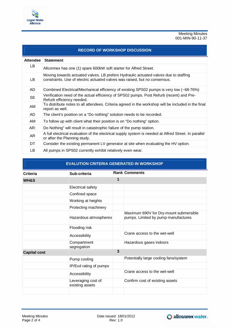
Meeting Minutes 001-MIN-90-11-37
Meeting Minutes Date issued: 18/01/2012 Page 2 of 4 Rev: 1.0
RECORD OF WORKSHOP DISCUSSION
Attendee Statement LB
Allconnex has one (1) spare 600kW soft starter for Alfred Street.
LB Moving towards actuated valves. LB prefers Hydraulic actuated valves due to staffing constraints. Use of electric actuated valves was raised, but no consensus.
AD Combined Electrical/Mechanical efficiency of existing SPS02 pumps is very low (~68-76%)
SE Verification need of the actual efficiency of SPS02 pumps. Post Refurb (recent) and Pre-Refurb efficiency needed.
AM To distribute notes to all attendees. Criteria agreed in the workshop will be included in the final report as well.
AD The client’s position on a “Do nothing” solution needs to be recorded.
AM To follow up with client what their position is on “Do nothing” option.
AR: Do Nothing” will result in catastrophic failure of the pump station.
AR A full electrical evaluation of the electrical supply system is needed at Alfred Street. In parallel or after the Planning study.
DT Consider the existing permanent LV generator at site when evaluating the HV option.
LB All pumps in SPS02 currently exhibit relatively even wear.
EVALUTION CRITERIA GENERATED IN WORKSHOP
Criteria Sub-criteria Rank Comments
WH&S 1
Electrical safety
Confined space
Working at heights
Protecting machinery
Hazardous atmospheres Maximum 690V for Dry-mount submersible
pumps. Limited by pump manufactures
Flooding risk
Accessibility Crane access to the wet-well
Compartment segregation
Hazardous gases indoors
Capital cost 3
Pump cooling Potentially large cooling fans/system
IP/Exd rating of pumps
Accessibility Crane access to the wet-well
Leveraging cost of existing assets
Confirm cost of existing assets
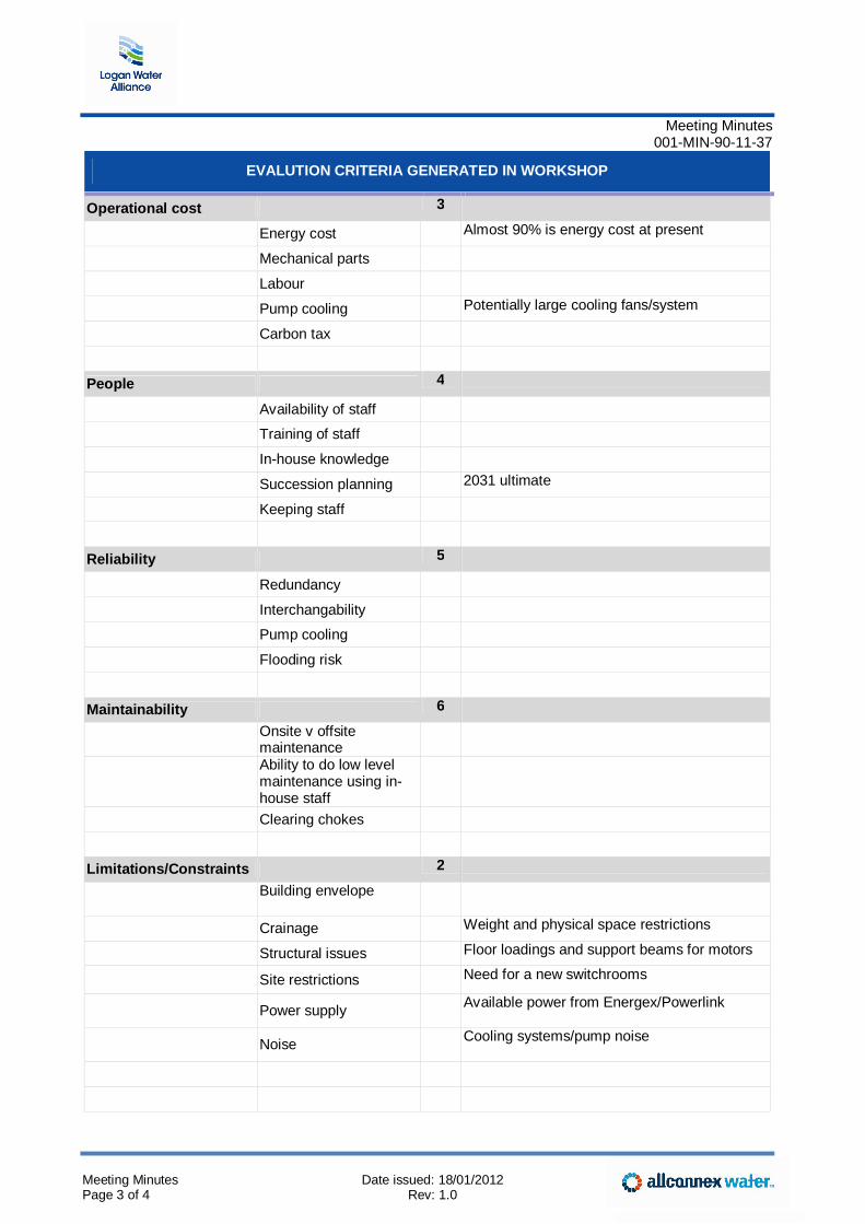
Meeting Minutes 001-MIN-90-11-37
Meeting Minutes Date issued: 18/01/2012 Page 3 of 4 Rev: 1.0
EVALUTION CRITERIA GENERATED IN WORKSHOP
Operational cost 3
Energy cost Almost 90% is energy cost at present
Mechanical parts
Labour
Pump cooling Potentially large cooling fans/system
Carbon tax
People 4
Availability of staff
Training of staff
In-house knowledge
Succession planning 2031 ultimate
Keeping staff
Reliability 5
Redundancy
Interchangability
Pump cooling
Flooding risk
Maintainability 6
Onsite v offsite maintenance
Ability to do low level maintenance using in-house staff
Clearing chokes
Limitations/Constraints 2
Building envelope
Crainage Weight and physical space restrictions
Structural issues Floor loadings and support beams for motors
Site restrictions Need for a new switchrooms
Power supply Available power from Energex/Powerlink
Noise Cooling systems/pump noise
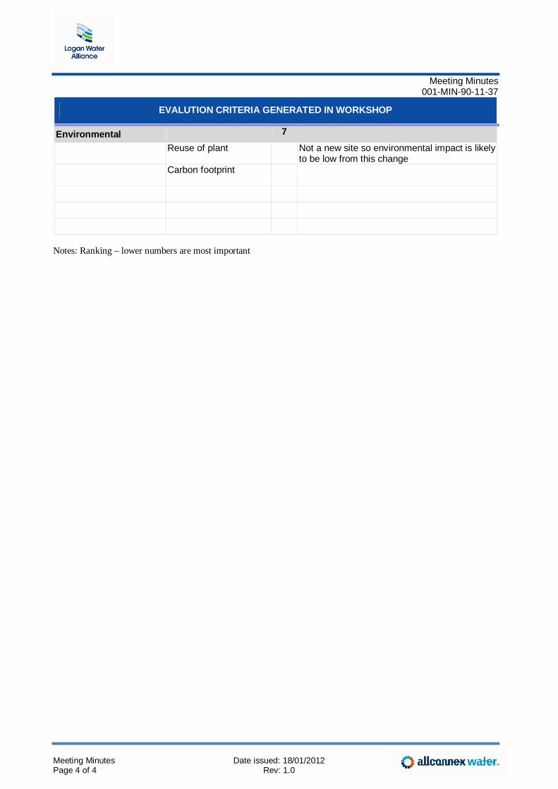
Meeting Minutes 001-MIN-90-11-37
Meeting Minutes Date issued: 18/01/2012 Page 4 of 4 Rev: 1.0
EVALUTION CRITERIA GENERATED IN WORKSHOP
Environmental 7
Reuse of plant
Not a new site so environmental impact is likely to be low from this change
Carbon footprint
Notes: Ranking – lower numbers are most important