Embed Size (px)
Citation preview
1
Logistics Report
Project: Humpty Doo.
9063
Flown for
Acacia Minerals Ltd
2
CONTENTS
SPECIFICATIONS FOR AIRBORNE GEOPHYSICAL SURVEY
SURVEY AREA .................................................................................................................... 3
CALIBRATION .................................................................................................................... 6
IN-FIELD VERIFICATION AND PROCESSING ............................................................. 8
NAVIGATION AND POSITIONING ............................................................................... 9
DIURNAL MONITOR ......................................................................................................... 9
DAILY REPORTS OF AIRCRAFT VH-AVN .................................................................. 10
AIRCRAFT AND SURVEY INSTRUMENTATION
AIRCRAFT VH – VH-AVN ............................................................................................... 11
SURVEY INSTRUMENTATION ...................................................................................... 12
MAGNETOMETER AND COMPENSATOR ................................................................... 12
RADAR ALTIMETER ....................................................................................................... 12
BAROMETRIC ALTIMETER .......................................................................................... 12
DATA ACQUISITION SYSTEM ....................................................................................... 12
NAVIGATION EQUIPMENT ........................................................................................... 13
BASE STATION MAGNETOMETER .............................................................................. 13
GAMMA RAY SPECROMETER SYSTEM ..................................................................... 13
CONTACT INFORMATION ............................................................................................ 14
3
SPECIFICATIONS FOR AIRBORNE GEOPHYSICAL SURVEY SURVEY AREA
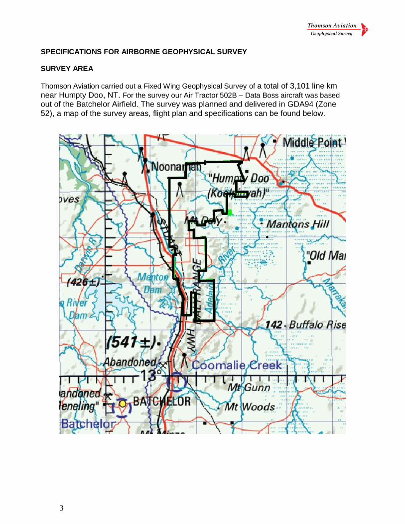
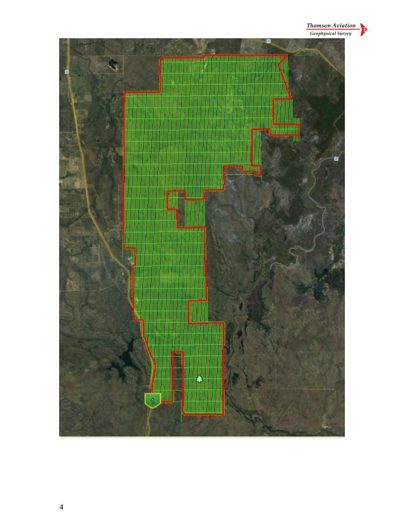
Thomson Aviation carried out a Fixed Wing Geophysical Survey of a total of 3,101 line km near Humpty Doo, NT. For the survey our Air Tractor 502B – Data Boss aircraft was based
out of the Batchelor Airfield. The survey was planned and delivered in GDA94 (Zone 52), a map of the survey areas, flight plan and specifications can be found below.
4
5
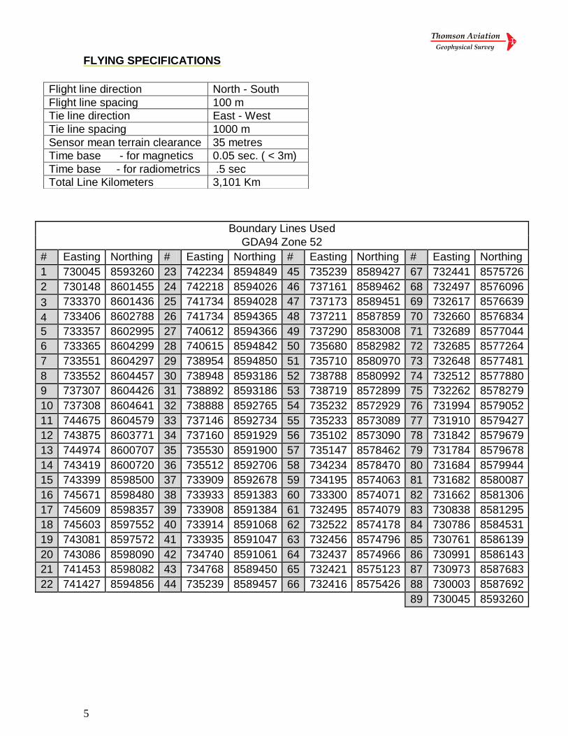
FLYING SPECIFICATIONS
Boundary Lines Used
GDA94 Zone 52
# Easting Northing # Easting Northing # Easting Northing # Easting Northing
1 730045 8593260 23 742234 8594849 45 735239 8589427 67 732441 8575726
2 730148 8601455 24 742218 8594026 46 737161 8589462 68 732497 8576096
3 733370 8601436 25 741734 8594028 47 737173 8589451 69 732617 8576639
4 733406 8602788 26 741734 8594365 48 737211 8587859 70 732660 8576834
5 733357 8602995 27 740612 8594366 49 737290 8583008 71 732689 8577044
6 733365 8604299 28 740615 8594842 50 735680 8582982 72 732685 8577264
7 733551 8604297 29 738954 8594850 51 735710 8580970 73 732648 8577481
8 733552 8604457 30 738948 8593186 52 738788 8580992 74 732512 8577880
9 737307 8604426 31 738892 8593186 53 738719 8572899 75 732262 8578279
10 737308 8604641 32 738888 8592765 54 735232 8572929 76 731994 8579052
11 744675 8604579 33 737146 8592734 55 735233 8573089 77 731910 8579427
12 743875 8603771 34 737160 8591929 56 735102 8573090 78 731842 8579679
13 744974 8600707 35 735530 8591900 57 735147 8578462 79 731784 8579678
14 743419 8600720 36 735512 8592706 58 734234 8578470 80 731684 8579944
15 743399 8598500 37 733909 8592678 59 734195 8574063 81 731682 8580087
16 745671 8598480 38 733933 8591383 60 733300 8574071 82 731662 8581306
17 745609 8598357 39 733908 8591384 61 732495 8574079 83 730838 8581295
18 745603 8597552 40 733914 8591068 62 732522 8574178 84 730786 8584531
19 743081 8597572 41 733935 8591047 63 732456 8574796 85 730761 8586139
20 743086 8598090 42 734740 8591061 64 732437 8574966 86 730991 8586143
21 741453 8598082 43 734768 8589450 65 732421 8575123 87 730973 8587683
22 741427 8594856 44 735239 8589457 66 732416 8575426 88 730003 8587692
89 730045 8593260
Flight line direction North - South
Flight line spacing 100 m
Tie line direction East - West
Tie line spacing 1000 m
Sensor mean terrain clearance 35 metres
Time base - for magnetics 0.05 sec. ( < 3m)
Time base - for radiometrics .5 sec
Total Line Kilometers 3,101 Km
6
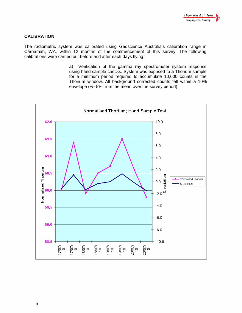
CALIBRATION
The radiometric system was calibrated using Geoscience Australia’s calibration range in Carnamah, WA, within 12 months of the commencement of this survey. The following calibrations were carried out before and after each days flying:
a) Verification of the gamma ray spectrometer system response using hand sample checks. System was exposed to a Thorium sample for a minimum period required to accumulate 10,000 counts in the Thorium window. All background corrected counts fell within a 10% envelope (+/- 5% from the mean over the survey period).
7
b) A Test Line was flown at the same height as the survey specified height to verify magnetometer, spectrometer and barometric altimeter baselines. The test line was flown over a repeatable line of five kilometers and was flown in either direction. The test line Thorium window counts fell within a 10% envelope (+/- 5% of the mean over the survey period).
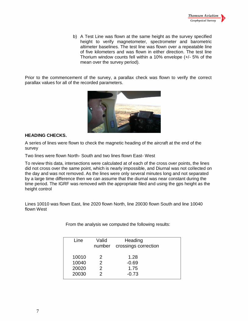
Prior to the commencement of the survey, a parallax check was flown to verify the correct parallax values for all of the recorded parameters.
HEADING CHECKS.
A series of lines were flown to check the magnetic heading of the aircraft at the end of the survey
Two lines were flown North- South and two lines flown East- West
To review this data, intersections were calculated at of each of the cross over points, the lines did not cross over the same point, which is nearly impossible, and Diurnal was not collected on the day and was not removed. As the lines were only several minutes long and not separated by a large time difference then we can assume that the diurnal was near constant during the time period. The IGRF was removed with the appropriate filed and using the gps height as the height control
Lines 10010 was flown East, line 2020 flown North, line 20030 flown South and line 10040 flown West
From the analysis we computed the following results:
Line Valid Heading number crossings correction 10010 2 1.28 10040 2 -0.69 20020 2 1.75 20030 2 -0.73
8
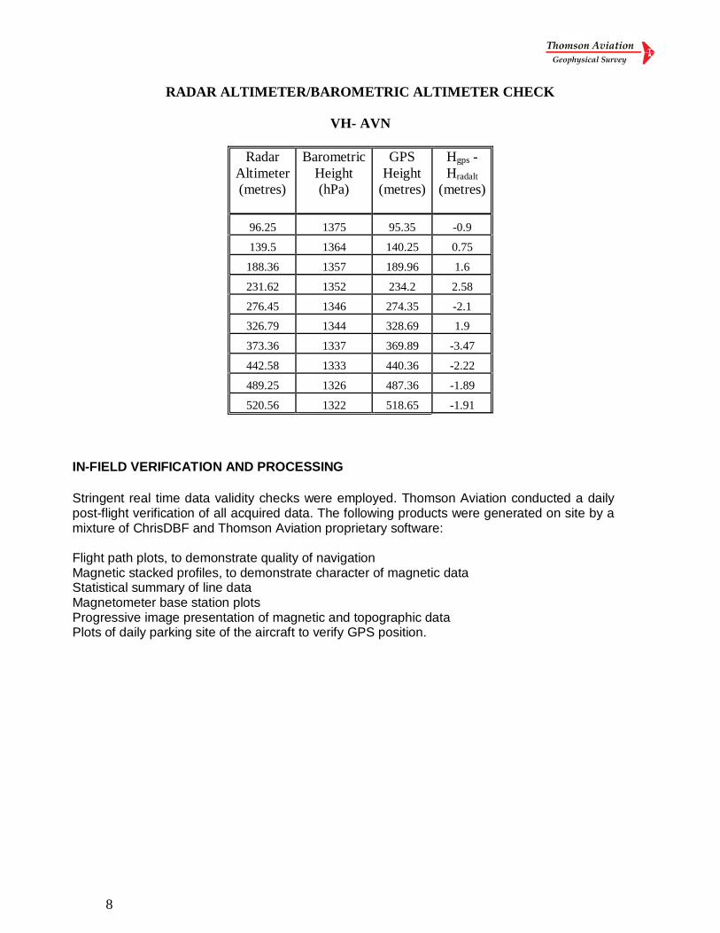
RADAR ALTIMETER/BAROMETRIC ALTIMETER CHECK
VH- AVN
Radar
Altimeter
(metres)
Barometric
Height
(hPa)
GPS
Height
(metres)
Hgps -
Hradalt
(metres)
96.25 1375 95.35 -0.9
139.5 1364 140.25 0.75
188.36 1357 189.96 1.6
231.62 1352 234.2 2.58
276.45 1346 274.35 -2.1
326.79 1344 328.69 1.9
373.36 1337 369.89 -3.47
442.58 1333 440.36 -2.22
489.25 1326 487.36 -1.89
520.56 1322 518.65 -1.91
IN-FIELD VERIFICATION AND PROCESSING
Stringent real time data validity checks were employed. Thomson Aviation conducted a daily post-flight verification of all acquired data. The following products were generated on site by a mixture of ChrisDBF and Thomson Aviation proprietary software: Flight path plots, to demonstrate quality of navigation Magnetic stacked profiles, to demonstrate character of magnetic data Statistical summary of line data Magnetometer base station plots Progressive image presentation of magnetic and topographic data Plots of daily parking site of the aircraft to verify GPS position.
9
NAVIGATION AND POSITIONING
Navigation was by electronic means using a mobile Novatel OEMV-1 VBS receiver to provide flight guidance to the pilot as well as recording the flight path for subsequent processing. Differential GPS data was obtained in real time using static GPS data obtained from the “Omnistar” wide area GPS service. Position relative to the survey line was displayed to the pilot by a system proprietary to Thomson Aviation which has proven highly effective. Under normal circumstances differential GPS is expected to yield positional accuracies in the order of 5 metres RMS or better.
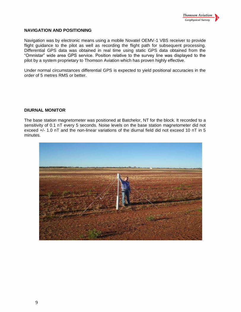
DIURNAL MONITOR The base station magnetometer was positioned at Batchelor, NT for the block. It recorded to a sensitivity of 0.1 nT every 5 seconds. Noise levels on the base station magnetometer did not exceed +/- 1.0 nT and the non-linear variations of the diurnal field did not exceed 10 nT in 5 minutes.
10
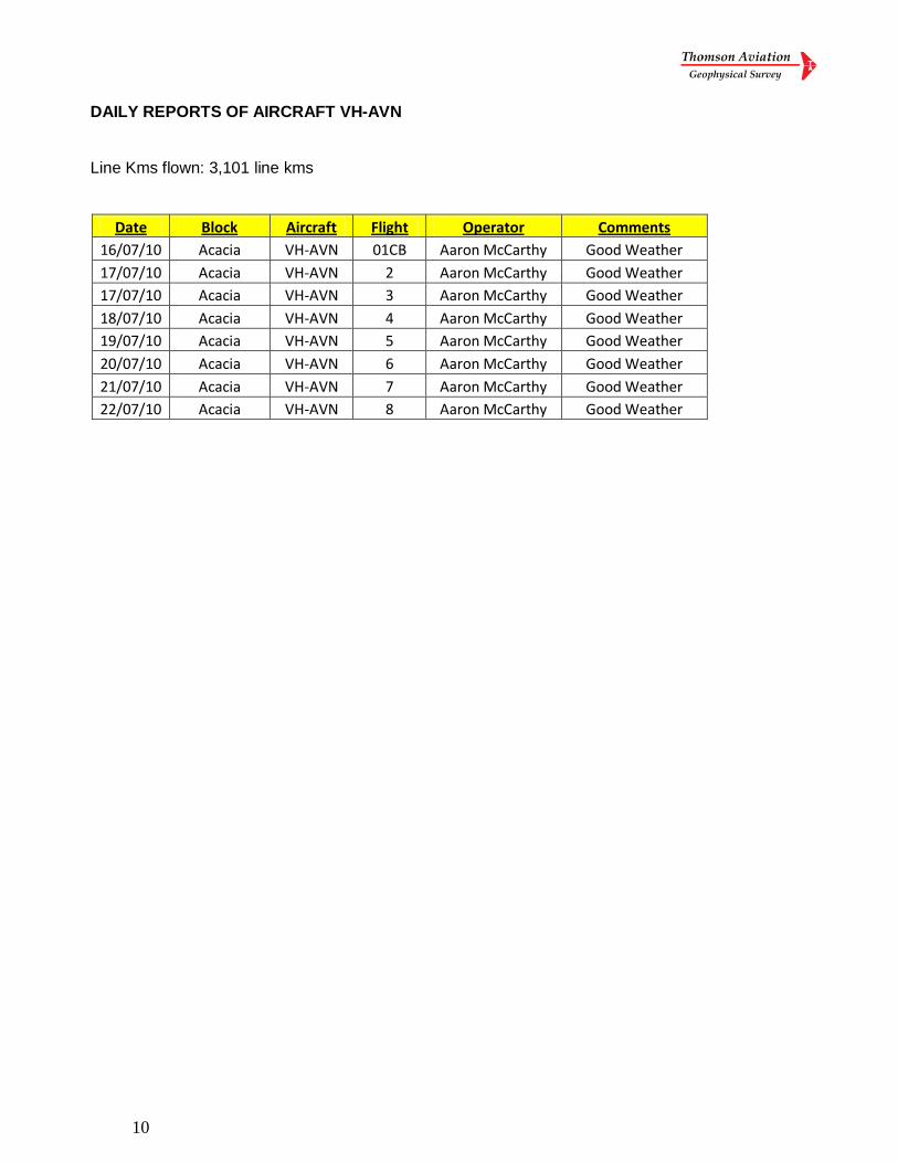
DAILY REPORTS OF AIRCRAFT VH-AVN
Line Kms flown: 3,101 line kms
Date Block Aircraft Flight Operator Comments
16/07/10 Acacia VH-AVN 01CB Aaron McCarthy Good Weather
17/07/10 Acacia VH-AVN 2 Aaron McCarthy Good Weather
17/07/10 Acacia VH-AVN 3 Aaron McCarthy Good Weather
18/07/10 Acacia VH-AVN 4 Aaron McCarthy Good Weather
19/07/10 Acacia VH-AVN 5 Aaron McCarthy Good Weather
20/07/10 Acacia VH-AVN 6 Aaron McCarthy Good Weather
21/07/10 Acacia VH-AVN 7 Aaron McCarthy Good Weather
22/07/10 Acacia VH-AVN 8 Aaron McCarthy Good Weather
11
AIRCRAFT AND SURVEY INSTRUMENTATION
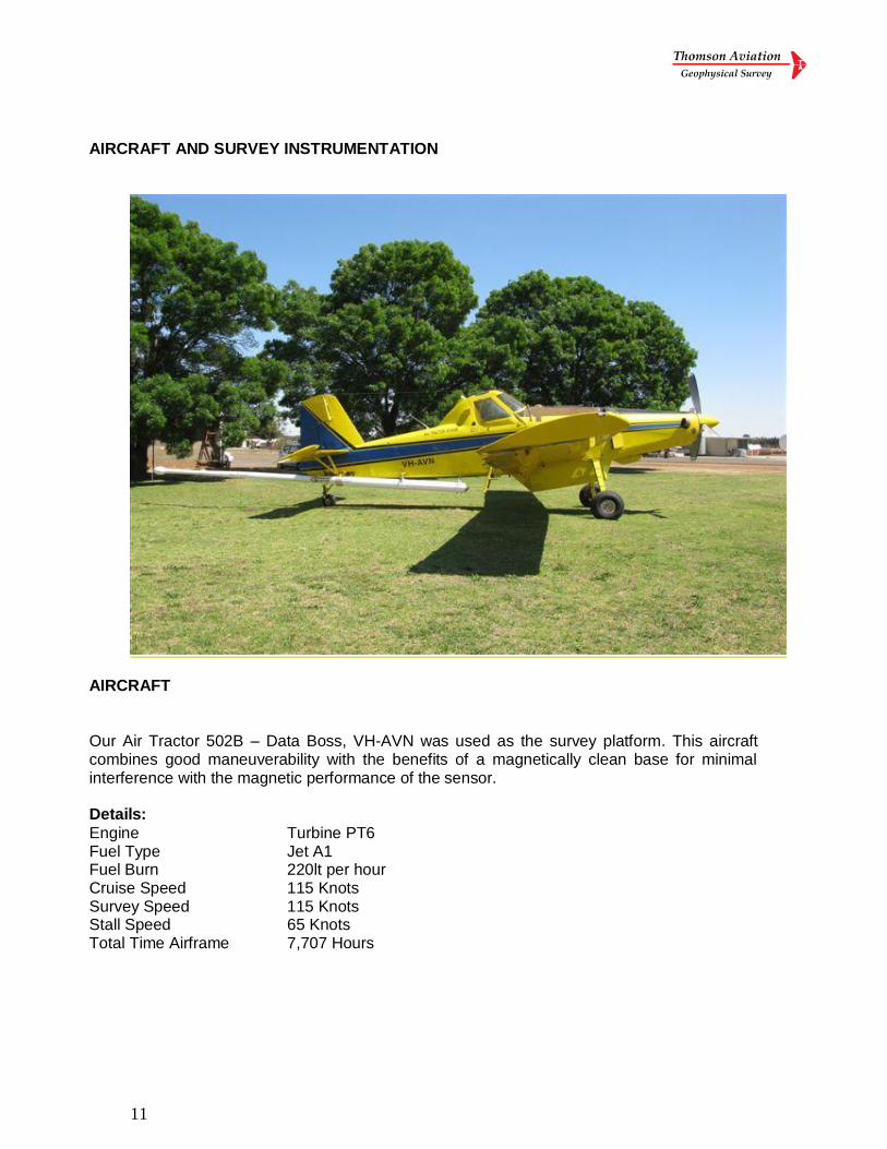
AIRCRAFT
Our Air Tractor 502B – Data Boss, VH-AVN was used as the survey platform. This aircraft combines good maneuverability with the benefits of a magnetically clean base for minimal interference with the magnetic performance of the sensor. Details:
Engine Turbine PT6 Fuel Type Jet A1 Fuel Burn 220lt per hour Cruise Speed 115 Knots Survey Speed 115 Knots Stall Speed 65 Knots Total Time Airframe 7,707 Hours
12
SURVEY INSTRUMENTATION
MAGNETOMETER AND COMPENSATOR
The Geometrics G822A Magnetometer is a highly sensitive unit incorporating an optically pumped sensor. The constant harmonic frequency from the sensor is proportional to the surrounding scalar magnetic field. This frequency is resolved by the Counter / Processor which provided the magnetic field to a nominal accuracy of 0.01nT at 20 times per second both in analog and digital forms. The sensor and pre-amp are stinger mounted, attached to the rear of the aircraft.
A Pico Envirotec MMS-4 processor was used to correct, in real time, for the magnetic interference caused by the aircraft itself and the effects of it maneuvering in the earth’s magnetic field. The signal from the magnetometer is preserved without aliasing or phase distortion. The raw uncompensated data was also recorded. RADAR ALTIMETER
A King KR 495B Radar Altimeter was used, this unit is a high resolution, short pulse ratio altitude system designed for automatic continuous operation over a wide variation of terrain, target reflectivity, weather and aircraft altitude. The radar altimeter indicator provided a terrain clearance display from 0 – 650 metres (0 – 2,000 feet) above ground. BAROMETRIC ALTIMETER
Barometric pressure was recorded using a Vaisela pressure transducer with a range of 600 to 1600 Hpa and a resolution of 0.04 Hpa (equivalent to 0.4 metres). The sensor was calibrated to the height given by the GPS. DATA ACQUISITION SYSTEM
The GeOZ_DAS digital data acquisition system recorded all system parameters to removable Flash Cards and provided both pilot guidance and error reporting diagnostics for the pilot or operator. Data was transferred to a field computer for both verification and archiving prior to being shipped to the processing centre.
13
NAVIGATION EQUIPMENT
The GPS receiver was a Novatel OEMV-1VBS 12 channel parallel tracking receiver capable of providing sub-metre resolution at five times per second. The GPS receiver was integrated within the GeOZ-DAS acquisition unit. BASE STATION MAGNETOMETER
Two Geometrics G-856 magnetometers with analog and digital recording were used as diurnal monitors and run continuously during the survey periods. GAMMA RAY SPECROMETER SYSTEM Two Radiations Solutions Inc. RSX-4 Gamma detector systems delivered high-resolution spectral information from 0.33 MeV to 3.0 MeV. In addition, the five primary regions of interest; Total Count, Potassium, Uranium, Thorium and Cosmic were provided. The Gamma Ray Spectrometer was interfaced to a NaI (Tl) crystal detector pack with a total volume of 33 litres (2048 cubic inches). The detector packs embody the latest techniques whereby the elimination of dead time in the counting process yields up to 30% more counts over competing systems. Superior calibration facilities included the visual real time monitoring of full spectrum data and in flight monitoring of gain drift relative to the selected isotope window, to ensure that long-term data quality was maintained. Enhancement of the spectrometer data was achieved by noise reduction techniques (NASVD or MNF), followed by dead time correction, energy calibration, cosmic/aircraft background correction and atmospheric radon removal all applied to the 256 channel data. Spectral stripping, height correction and conversion to radio-element concentrations were then applied prior to gridding and microlevelling.
14
Contact Information Paul Rogerson, Director
Thomson Aviation Pty Limited ABN 88 125 552 132
Main Office: Hanger 14, Griffith Airport, 2680, Australia. Phone: 02 6964 9487 Fax: 02 6962 2992 Mobile: 0427 681484 (Paul Rogerson) Email: [email protected] Postal address: PO Box 1845 Griffith NSW, 2680