Embed Size (px)
Citation preview
SMC-TR-06-09 AEROSPACE REPORT NO.TR-2006(1550)-i
Long-Term Storage of the Solar Arraysfor the Defense Meteorological SatelliteProgram (DMSP) 5D3 Spacecraft
(6.3) Environmental Testing and Space Systems
10 February 2006
Prepared by
E. J. SIMBURGERElectronics and Photonics LaboratoryLaboratory OperationsThe Aerospace Corporation
W. L. BUNSELMEYERLockheed Martin Space Systems CompanySunnyvale, CA 94088
Prepared for
SPACE AND MISSILE SYSTEMS CENTERAIR FORCE SPACE COMMAND2430 E. El Segundo BoulevardLos Angeles Air Force Base, CA 90245
Engineering and Technology Group
APPROVED FOR PUBLIC RELEASE;THE A O1 DISTRIBUTION UNLIMITED
CORORAIO
El Se u d ,C lf r i
This report was submitted by The Aerospace Corporation, El Segundo, CA 90245-4691, under Con-tract No. FA8802-04-C-0001 with the Space and Missile Systems Center, 2430 E. El SegundoBlvd., Los Angeles Air Force Base, CA 90245. It was reviewed and approved for The AerospaceCorporation by B. Jaduszliwer, Principal Director, Electronics and Photonics Laboratory; and P. H.Mak, Principal Director, Meteorological Satellite Systems. Lt. Col. John Varljen, Chief, Satellitesystems Division, was the cognizant officer for the program.
This report has been reviewed by the Public Affairs Office (PAS) and is releasable to the NationalTechnical Information Service (NTIS). At NTIS, it will be available to the general public, includingforeign nationals.
This technical report has been reviewed and is approved for publication. Publication of this reportdoes not constitute Air Force approval of the report's findings or conclusions. It is published onlyfor the exchange and stimulation of ideas.
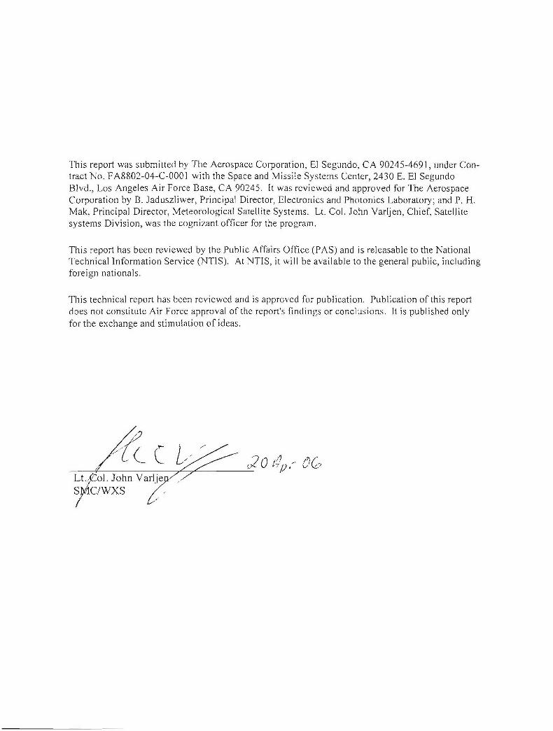
Form ApprovedREPORT DOCUMENTATION PAGE 0MB No. 0704-0188
Public reporting burden for this collection of information is estimated to average 1 hour per response, including the time for reviewing instructions, searching existing data sources,gathering and maintaining the data needed, and completing and reviewing this collection of information. Send comments regarding this burden estimate or any other aspect of thiscollection of information, including suggestions for reducing this burden to Department of Defense, Washington Headquarters Services, Directorate for Information Operations andReports (0704-0188), 1215 Jefferson Davis Highway, Suite 1204, Arlington, VA 22202-4302. Respondents should be aware that notwithstanding any other provision of law, no personshall be subject to any penalty for failing to comply with a collection of information if it does not display a currently valid OMB control number. PLEASE DO NOT RETURN YOUR FORMTO THE ABOVE ADDRESS.
1. REPORT DATE (DD-MM-YYYY) 2. REPORT TYPE 3. DATES COVERED (From - To)10-02-2006
4. TITLE AND SUBTITLE 5a. CONTRACT NUMBERFA8802-04-C-000 1
Long-Term Storage of the Solar Arrays for the Defense Meteorological Satellite 5b. GRANT NUMBERProgram (DMSP) 5D3 Spacecraft
5c. PROGRAM ELEMENT NUMBER
6. AUTHOR(S) 5d. PROJECT NUMBER
E. J. Simburger and W. L. Bunselmeyer 5e. TASK NUMBER
5f. WORK UNIT NUMBER
7. PERFORMING ORGANIZATION NAME(S) AND ADDRESS(ES) 8. PERFORMING ORGANIZATION
REPORT NUMBER
The Aerospace CorporationLaboratory OperationsEl Segundo, CA 90245-4691 TR-2006(1550)-i
9. SPONSORING / MONITORING AGENCY NAME(S) AND ADDRESS(ES) 10. SPONSOR/MONITOR'S ACRONYM(S)Space and Missile Systems Center SMCAir Force Space Command2450 E. El Segundo Blvd. 11. SPONSOR/MONITOR'S REPORTLos Angeles Air Force Base, CA 90245 NUMBER(S)
SMC-TR-06-0912. DISTRIBUTION/AVAILABILITY STATEMENT
Approved for public release; distribution unlimited.
13. SUPPLEMENTARY NOTES
14. ABSTRACT
Lockheed Martin built the United States Air Force's DMSP 5D-3 Spacecraft. The satellite was designed for a missionthat consists of two years of ground storage and 45 days of prelaunch checkout, followed by 3-1/2 years of operational life.The 5D-3 spacecraft will operate in a circular, sun-synchronous orbit with an inclination of 98.7' at an altitude of 458 nmi.The build of five 5D-3 spacecraft was completed in 1997. The first 5D-3 satellite, designated F-16, was launched on Oct-ober 18, 2003 after six years of storage.
The next 5D-3 DMSP, designated F-17, is scheduled to be launched in 2006. The remaining three satellites will belaunched roughly every two years to maintain the two-satellite DMSP constellation. The final DMSP satellite may not belaunched until 2012, after 16 years of storage!
Thus, the Air Force is concerned about the age of the DMSP spacecraft hardware and possible age-related degradationof the hardware. This report examines how well the solar arrays for the 5D-3 spacecraft withstood the extended storage atthe Lockheed Martin plant located in Sunnyvale California.
15. SUBJECT TERMS
Solar arrays, Silicon photovoltaic technology, Space systems, Long-term storage
16. SECURITY CLASSIFICATION OF: 17. LIMITATION 18. NUMBER 19a. NAME OFOF ABSTRACT OF PAGES RESPONSIBLE PERSON
Ed Simburgera. REPORT b. ABSTRACT c. THIS PAGE 19b. TELEPHONE NUMBER
(include area code)UNCLASSIFIED UNCLASSIFIED UNCLASSIFIED (310)336-7186
Standard Form 298 (Rev. 8-98)Prescribed by ANSI Std. 239.18
Contents
1. D escription of the 5D -3 Solar A rrays .............................................................................................. 1
2. Results of I-V Testing of the DMSP S-17 Solar Array ................................................................. 5
3 . C o n c lu sio n s ....................................................................................................................................... 7
Figures
1. Photo of deployed solar array for DMSP S-17 spacecraft ....................................................... 1
2. Artist's rendition of DMSP 5D-3 spacecraft on orbit with deployed solar array .................. 1
3. DMSP 16-20 peak solar array capacity in June at the end of five years on orbit .................. 2
4. DMSP 16-20 peak solar array capacity in December to the end of five years on orbit ........ 2
5. Sample schematic for each of 70 solar array circuits .............................................................. 3
6 . I-V C urves for C ircuit 4 Panel A t ............................................................................................ 5
7 . I-V C urve for C ircuit 4A Panel A l ........................................................................................... 6
8 . I-V C urve for C ircuit 4 B Panel A l ........................................................................................... 6
Table
1. Summary of I-V Characteristic Test Results Summary .......................................................... 5
iii
1. Description of the 5D-3 Solar Arrays
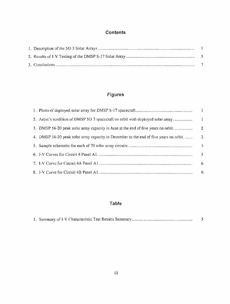
The solar array includes ten flat structurally identical solar cell panels. The ten panels are assembledinto two five packs that are attached to the solar array boom. When deployed, the two five packs arepositioned into a single plane symmetrical around the solar-array boom, as shown in Figure 1.
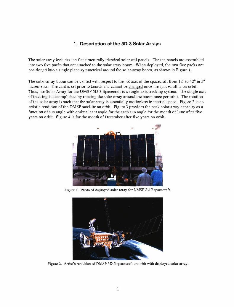
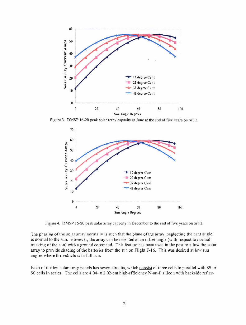
The solar-array boom can be canted with respect to the +Z axis of the spacecraft from 120 to 420 in 50increments. The cant is set prior to launch and cannot be changed once the spacecraft is on orbit.Thus, the Solar Array for the DMSP 5D-3 Spacecraft is a single-axis tracking system. The single axisof tracking is accomplished by rotating the solar array around the boom once per orbit. The rotationof the solar array is such that the solar array is essentially motionless in inertial space. Figure 2 is anartist's rendition of the DMSP satellite on orbit. Figure 3 provides the peak solar array capacity as afunction of sun angle with optimal cant angle for the each sun angle for the month of June after fiveyears on orbit. Figure 4 is for the month of December after five years on orbit.
-7
Figure 1. Photo of deployed solar array for DMSP S-17 spacecraft.
Figure 2. Artist's rendition of DMSP 5D-3 spacecraft on orbit with deployed solar array.
I
60
a50E
. 40/
S30
< 20 9" 12 degree Cant- 22 degree Cant
S"0 32 degree Cant10 42 degree Cant
0 20 40 60 80 100Sun Angle Degrees
Figure 3. DMSP 16-20 peak solar array capacity in June at the end of five years on orbit.
70
60'
E< 50
P 40
S30 12 degree Cani"i 22 degree Cant•- 20 '
332 degree Cant(A 10-42 degree Cantl0
0 20 40 60 80 100Sun Angle Degrees
Figure 4. DMSP 16-20 peak solar array capacity in December to the end of five years on orbit.
The phasing of the solar array normally is such that the plane of the array, neglecting the cant angle,is normal to the sun. However, the array can be oriented at an offset angle (with respect to normaltracking of the sun) with a ground command. This feature has been used in the past to allow the solararray to provide shading of the batteries from the sun on Flight F-16. This was desired at low sunangles where the vehicle is in full sun.
Each of the ten solar array panels has seven circuits, which consist of three cells in parallel with 89 or90 cells in series. The cells are 4.04- x 2.02-cm high-efficiency N-on-P silicon with backside reflec-
2
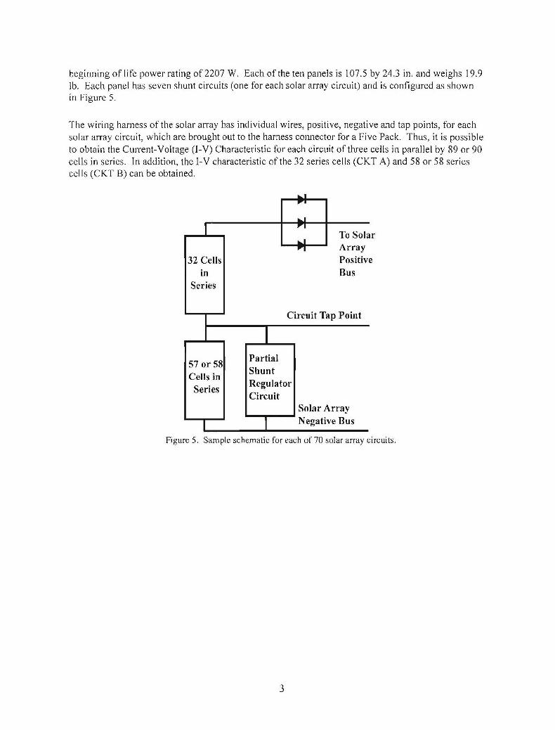
beginning of life power rating of 2207 W. Each of the ten panels is 107.5 by 24.3 in. and weighs 19.9lb. Each panel has seven shunt circuits (one for each solar array circuit) and is configured as shownin Figure 5.
The wiring harness of the solar array has individual wires, positive, negative and tap points, for eachsolar array circuit, which are brought out to the harness connector for a Five Pack. Thus, it is possibleto obtain the Current-Voltage (I-V) Characteristic for each circuit of three cells in parallel by 89 or 90cells in series. In addition, the I-V characteristic of the 32 series cells (CKT A) and 58 or 58 seriescel Is (CKT B) can be obtained.
To Solar
Soa Array32 Cells Positive
in BusSeries
Circuit Tap Point
5 Partial57 or 58 Sh nCellsies Regulator
Series CircuitSolar Array
S Negative Bus
Figure 5. Sample schematic for each of 70 solar array circuits.
3
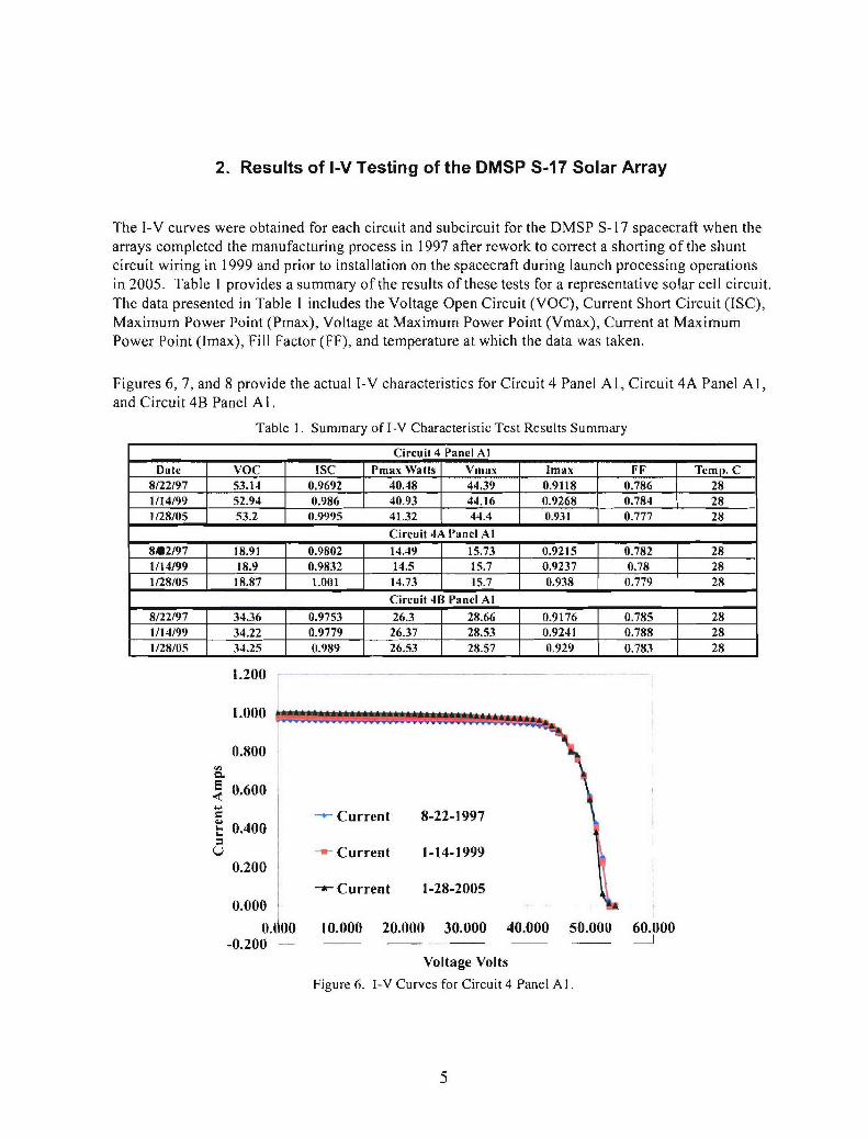
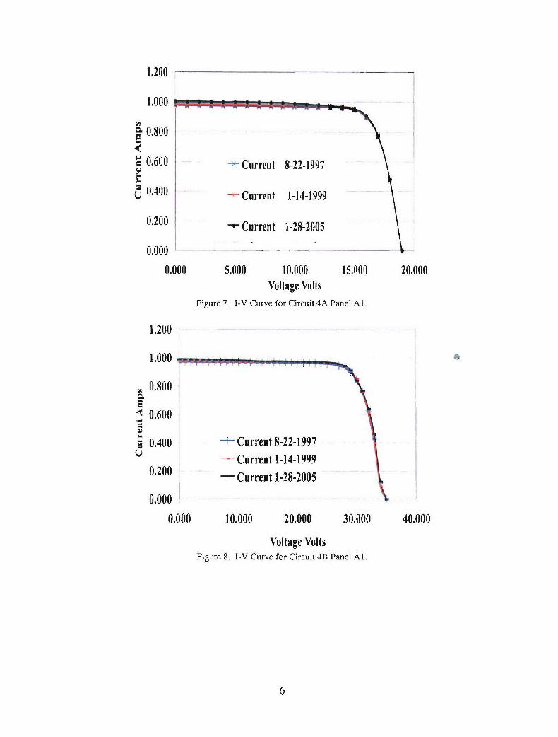
2. Results of I-V Testing of the DMSP S-17 Solar Array
The I-V curves were obtained for each circuit and subcircuit for the DMSP S-17 spacecraft when thearrays completed the manufacturing process in 1997 after rework to correct a shorting of the shuntcircuit wiring in 1999 and prior to installation on the spacecraft during launch processing operationsin 2005. Table I provides a summary of the results of these tests for a representative solar cell circuit.The data presented in Table 1 includes the Voltage Open Circuit (VOC), Current Short Circuit (ISC),Maximum Power Point (Pmax), Voltage at Maximum Power Point (Vmax), Current at MaximumPower Point (Imax), Fill Factor (FF), and temperature at which the data was taken.
Figures 6, 7, and 8 provide the actual I-V characteristics for Circuit 4 Panel Al, Circuit 4A Panel A],and Circuit 4B Panel Al.
Table 1. Summary of I-V Characteristic Test Results Summary
Circuit 4 Panel A]Date VOC ISC Pmax Watts Vmax Imax FF Temp. C
8/22/97 53.14 0.9692 40.48 44.39 0.9118 0.786 281/14/99 52.94 0.986 40.93 44.16 0.9268 0.784 281/28/05 53.2 0.9995 41.32 44.4 0.931 0.777 28
Circuit 4A Panel Al8*2/97 18.91 0.9802 14.49 15.73 0.9215 0.782 281/14/99 18.9 0.9832 14.5 15.7 0.9237 0.78 281/28/05 18.87 1.001 14.73 15.7 0.938 0.779 28
Circuit 4B Panel Al8/22/97 34.36 0.9753 26.3 28.66 0.9176 0.785 281/14/99 34.22 0.9779 26.37 28.53 0.9241 0.788 281/28/05 34.25 0.989 26.53 28.57 0.929 0.783 28
1.200
0.800CL
E 0.600
"- Current 8-22-1997S0.400Si - Current 1-14-1999
0.200 I
-- Current 1-28-20050.000
0.1 00 10.000 20.000 30.000 40.000 50.000 60.000-0.200 __ _ -
Voltage Volts
Figure 6. I-V Curves for Circuit 4 Panel A 1.
5
1.200
1.000
0.800
• 0.600 Current 8-22-1997
U 0.400 -Current 1-14-1999
0.200 -.- Current 1-28-2005
0.000
0.000 5.000 10.000 15.000 20.000Voltage Volts
Figure 7. I-V Curve for Circuit 4A Panel Al.
1.200
1.000
0.800E< 0.600
. 0.400 Current 8-22-1997SCurrent 1-14-1999
0.200 - Current 1-28-2005
0.000
0.000 10.000 20.000 30.000 40.000
Voltage VoltsFigure 8. I-V Curve for Circuit 4B Panel Al.
3. Conclusions
The tests performed to date on the DMSP S-17 solar array do not show any degradation over theperiod of time that the array was in storage. A method has been demonstrated whereby I-V curves ofthe individual 70 circuits taken over the period of time in storage are compared to determine thehealth of the solar arrays after extended storage periods.
7
LABORATORY OPERATIONS
The Aerospace Corporation functions as an "architect-engineer" for national security programs, specializing inadvanced military space systems. The Corporation's Laboratory Operations supports the effective and timelydevelopment and operation of national security systems through scientific research and the application ofadvanced technology. Vital to the success of the Corporation is the technical staffs wide-ranging expertise andits ability to stay abreast of new technological developments and program support issues associated with rapidlyevolving space systems. Contributing capabilities are provided by these individual organizations:
Electronics and Photonics Laboratory: Microelectronics, VLSI reliability, failure analysis,solid-state device physics, compound semiconductors, radiation effects, infrared and CCDdetector devices, data storage and display technologies; lasers and electro-optics, solid-statelaser design, micro-optics, optical communications, and fiber-optic sensors; atomic frequencystandards, applied laser spectroscopy, laser chemistry, atmospheric propagation and beamcontrol, L[DAR/LADAR remote sensing; solar cell and array testing and evaluation, batteryelectrochemistry, battery testing and evaluation.
Space Materials Laboratory: Evaluation and characterizations of new materials andprocessing techniques: metals, alloys, ceramics, polymers, thin films, and composites;
development of advanced deposition processes; nondestructive evaluation, component failureanalysis and reliability: structural mechanics, fracture mechanics, and stress corrosion; analysisand evaluation of materials at cryogenic and elevated temperatures; launch vehicle fluidmechanics, heat transfer and flight dynamics; aerothermodynamics; chemical and electricpropulsion; environmental chemistry; combustion processes; space environment effects onmaterials, hardening and vulnerability assessment; contamination, thermal and structuralcontrol; lubrication and surface phenomena. Microelectromechanical systems (MEMS) forspace applications; laser micromachining; laser-surface physical and chemical interactions;micropropulsion: micro- and nanosatellite mission analysis; intelligent microinstruments formonitoring space and launch system environments.
Space Science Applications Laboratory: Magnetospheric, auroral and cosmic-ray physics,wave-particle interactions, magnetospheric plasma waves; atmospheric and ionospheric physics,density and composition of the upper atmosphere, remote sensing using atmospheric radiation;solar physics, infrared astronomy, infrared signature analysis; infrared surveillance, imaging andremote sensing; multispectral and hyperspectral sensor development; data analysis andalgorithm development; applications of multispectral and hyperspectral imagery to defense, civilspace, commercial, and environmental missions; effects of solar activity, magnetic storms andnuclear explosions on the Earth's atmosphere, ionosphere and magnetosphere; effects ofelectromagnetic and particulate radiations on space systems; space instrumentation, design,fabrication and test; environmental chemistry, trace detection; atmospheric chemical reactions,atmospheric optics, light scattering, state-specific chemical reactions, and radiative signatures ofmissile plumes.
THE AEROSPACECORPORATION
2350 F El Segundo BoutevardEl Segundo, California 90245-4691
USA.