Embed Size (px)
Citation preview

Long wavelength IlnAs/lnGaSb infrared detectors: Optimization of carrier lifetimes
C. H. Grein Physics Department, University of Illinois at Chicago, Chicago, Illinois 60607-7059
P. M. Young, M. E. Flatt6,a1 and H. Ehrenreich Division of Applied Sciences, Harvard University, Cambridge, Massachusetts 02138
(Received 28 June 1995; accepted for publication 7 September 1995)
The performance characteristics of type-II InAs/InXGal-,Sb superlattices for long and very long-wave infrared detection are discussed. This system promises benefits in this wavelength range over conventional technology based on Hg,,,Cd,Te, in part because of suppressed band-to-band Auger recombination rates which lead to improved values of detectivity. The formalism for calculating Auger rates in superlattices is developed and the physical origin of Auger suppression in these systems is discussed. Accurate K.p band structures are used to obtain radiative, electron- electron, hole-hole, and band-to-band Auger rules, as well as shallow trap level assisted Auger recombination rates for photodiodes. Theoretical limits for high temperature operation of ideal photovoltaic detectors are presented and compared with HgCdTe. 0 1995 American Institute of Physics.
I. INTRODUCTION
The search for novel infrared detector materials is moti- vated by the need to increase background limited operating temperatures, thereby reducing or eliminating bulky and ex- pensive coolers. Increasing minority carrier lifetimes relative to bulk Hgt-,Cd,Te (MCT), the industry standard, will re- sult in increased detectivities at the same operating tempera- ture, or the same detectivity at a higher operating tempera- ture. Carrier lifetimes can be increased by “band structure engineering” heterosttuctures to suppress or eliminate Auger recombination pathways, often the dominant recombination mechanism in long wavelength IR, (LWJR, approximately 8-12 pm) and very long wavelength IR (VLWIR, approxi- mately 12-20 ,um) semiconductor-based detectors. This ar- ticle focuses on devices operating in the latter range requir- ing sharply tuned, very small band gaps that are difficult to achieve with the required uniformity in MCT and in which nonradiative Auger recombination is particularly important.
Subband gaps in the band structure of a quantum well or superlattice (SL) at the right energies can markedly reduce the available phase space for these Auger processes. Auger recombination suppression in a heterostructure was first con- sidered by Jiang, Teich, and Wang,‘,” who provided guide- lines for Auger suppression in InGaSb and InGaAs quantum wells,’ and later showed that the Auger rates in some MCT quantum wells are smaller than in MCT bulk.” However, their guidelines are only valid for much simplified parabolic bands, whereas heterostructure bands are highly nonpara- bolic. They further simplified their numerical calculations by assuming infinite barriers, parabolic bands, and momentum- independent momentum matrix elements. The results re- ported in this article rely on none of these simplifying ap- proximations.
“)Present address: Department of Physics and Astronomy, University of Iowa, Iowa City, Iowa 52242.
A system that shows great promise for permitting the suppression of Auger recombination in the VLWIR range is the strained-layer type-II InAs/In,Gat -,Sb SL.3,4 For this SL the band gap comes about because of carrier confinement of electrons and holes in the InAs and InGaSb layers, respec- tively, rather than from purely chemical composition as in MCT. The gap is therefore more highly controllable. This SL is typically grown on a GaSb substrate so that the InAs lay- ers are under slight biaxial tension and the alloy layers are under significant biaxial compression (up to 2%). Figure 1 illustrates the quantum confinement effects and those associ- ated with strain: the heavy-hole (HH) edge lies above the light-hole (LH) edge in the alloy layers in which the holes are confined. As a consequence, the highest SL LH band lies significantly below the SL HH band. This effect will be seen to lead to the suppression of Auger recombination.
This article provides a detailed description of the Auger theory in a form that is applicable to SLs, a physical discus- sion of how band structure optimization suppresses Auger processes in specific important cases, and a comparison of wide-ranging calculated results for the Auger lifetime 7 and the detectivity D” in both InAs/InGaSb SLs and bulk MCT. Some of these results have been presented before in frag- mentary form in relatively inaccessible conference proceed- ings. This article presents them in a unified way and thereby provides context and physical insight that can be seen as a guide to the band structure engineering required to optimize material properties. A detailed account of the generalized band formalism5 calculations5v6 *
used for this and our previous is in preparation.7
II. QUALITATIVE FEATURES OF BANDS AND AUGER RATES
SL electronic band structures were calculated employing an 8 band SL K-p formalism,5T6 with the input parameters given in Table I. Recent calculations employing 14 bands indicate that errors introduced with the employment of this
J. Appl. Phys. 78 (12), 15 December 1995 0021-8979/95/78( 12)/7143/1 O/$6.00 Q 1995 American Institute of Physics 7143

Energy
I
C
HH :::
In& . InGaSb
I HH
BIG. 1. Band alignment in InAs/In,Gat-,Sb type-II superlattices. Electrons are confined to InAs layers; and holes to In,Ga,-,Sb layers. Lattice mis- matches between these layers result in strain splitting of the LH and HH bands.
smaller basis set are small7 The bands are found to be highly nonparabolic. and the momentum matrix elements show strong dispersion. These realistic bands and matrix elements are used in the present lifetime calculations. The band struc- tures of three representative SLs, all with 11 pm gaps, are plotted in Fig. 2 in the in-plane (II) and growth-axis (I) di- rections. The first, 39.8 A InAs/ A Ina,~Ga,,$b [Fig. 2(a)], has been optimized to suppress Auger recombination when pdoped. The second, 41 A InAs/ %, In0,25Ga0.7sSb [Fig. 2(b)], is under experimental investigation.4 The third, 40.25 A InAs A In0,z,Gau7,Sb [Fig. 2(c)], has been optimized to suppress Auger recombination when n doped. Plots of the momentum matrix elements, illustrating their strong disper- sion, are also included in Fig. 2.
In an infrared detector, photons create electron-hole pairs. These pairs are typically created away from the p-n
junction depletion layer and must diffuse there to be sepa- rated and collected. During the diffusion, radiative and non- radiative recombination processes of these and thermal electron-hole pairs may contribute to the signal noise and reduce the carrier collection efficiency. Of particular impor- tance in high-quality VLWIR detectors is Auger recombina- tion. The Auger processes which primarily influence detector performance involve the scattering of two carriers (either two electrons or two holes) into unoccupied states. In Fig. 3(a), for example, the electron-hole pair (1,l’) decays nonradia- tively by an Auger process involving a screened Coulomb interaction which produces transition (2,2’). We find that the dominant band-to-band recombination transitions involving hole-hole collisions in the 11-19 pm SLs discussed in Sec. V are AM-7 transition. Typical AM-7 transitions in the LWIR regime are illustrated in Figs. 3(a) and 3(b) for bulk HgCdTe and InAslInGaSb. They involve two holes in the HI-I band, an electron in the lowest conduction band (C), and an elec- tron in the valence band immediately below the HH band (usually the LH band). One HH recombines with a conduc- tion electron and the other is excited to the valence band immediately below the HH band.
The dominant transitions involving electron-electron collisions are found to be AM-l, involving two electrons and an unoccupied state in the lowest conduction band, and a nonequilibrium hole in the HI-I band. Typical AM-l transi- tions in bulk HgCdTe and InAs/InGaSb SLs are illustrated in Figs. 4(a) and 4(b). One conduction electron recombines with a HH, and the other electron is excited to a higher state in the conduction band.
AM-7 Auger rates in bulk MCT have been calculated by Casselman,* Beattie,’ and Young et a2.i’ These results agree within a factor of 3 with each other and will be compared with SL rates in the final section. Our calculations of Auger rates in SLs are far more intensive numerically since they
TABLE I. Input values for K.p band structure calculations of InAs/InGaSb superlattices and bulk HgCdTe. Notes: All values are at T=O K. Hydrostatic deformation potentials of the valence bands are neglected. All parameters for IncuGac,sSb are linearly interpolated from InSb and GaSb unless otherwise noted in the InauGae7sSb column. The superlattice is assumed to be grown on a GaSb substrate.
Lattice constant (A) a deformation potential (eV)b b deformation potential (eV)b cI1 (10” dyn cm-‘) ct2 (10” dyn cm-*)* Energy gap (eV) Spin orbit splitting A (eV) m& in (100) direction” rnz averaged” 2/m[ P’$& (eV)b Valence band offset (eV)g Index of refraction na Dielectric constant &*
GaSb
6.096 --7.2 -1.8
8.834 4.023
0.758
0.042
InSb
6.479 -7.7 -2.0
6.918 3.788
0.803
IllAS
6.058 -5.8 -1.8
8.329 4.526 0.4180 0.38 0.4 0.022
Irb.z@odb
0.5913
0.35d
I~sb.z@mSb
22.8' 0.560 3.5
12.25
Hg,Cd, -,Te
o.114c 0.95 0.6
lS.Of
3.5 12.25
aReference 22. bReference 23. ‘Reference 24. dReference 25. eMomentum matrix element deduced from rnr of InAs and GaSb. ‘Reference 26. Qives best agreement with measured gaps (Ref. 27).
7144 J. Appt. Phys., Vol. 78, No. 12, 15 December 1995 Grein et a/.

s D
s
s L E 6’ x s
3 =g
(a) 39.8A InAs 5A In,,Ga,,$b
2.0
1.5
1.0
0.5
0.0
-x./d 0 n/d -nld Q Ir/d
011) .. (c)’ ; 41 A lnAsl25A In,,,Ga&b 4O.25A lnAs/32A In,,,Ga&b
1.5
1.0
0.5
0.0
-Ir/d 0 Idd
FG. 2. Band structures E,(K) and energies IP~,,(K)j2/ m = 1 (L,K~~~~IL’,K)I*I~ for 41 A InAs/ 8, In,,,Ga,,,,Sb, 39.8 A InAs/ 8, h.,Ga,,,Sb, and 40.25 A InAs/ A J&.~G%.&b superlattices shown as a functions of 41 and K, . The origin of the energy scale is defined as the valence band (rs) edge of GaSb. The label L-L’ indicates the transition corresponding to I&,,(K)12/m. The superlattice growth axis is along the I direction.
involve the full nonparabolic band structure and momentum- dependent matrix elements.
In SLs the widths of the two constituent layers are com- parable, and both affect the band structure. Thus two param- eters can be varied independently rather than the single one of a quantum well. The remainder of this section provides guidance for selecting optimal band structures.
We fist discuss recombination processes in p-type ma- terial. The bands of the 39.8 rf InAs/ A Ina,Gaa,6Sb SL, shown in Fig. 2(a), have been optimized to suppress p-type Auger processes (AM-7). The strain in the InGaSb layer splits the LH and HJ5 degeneracy and forces the second high- est valence subband (LHl) to lie almost twice the fundamen- tal gap below the highest subband (HHl) in the in-plane direction. In such a band structure, momentum and energy conservation preclude electrons at the conduction band mini- mum from recombining with holes at the valence band maxi- mum. Instead, the dominant Auger processes involves an initial-state hole located far away from the zone center in the in-plane direction, approximately 200 meV below the top of the valence band. Such a process is shown in Fig. 3(b). Since this region of the Brillouin zone (BZ) contains few holes, Auger rates can be suppressed by orders of magnitude in optimized band structures. As the temperature increases the holes spread out over larger regions of the BZ, and the mechanism just discussed for suppressing Auger rates is less
J. Appl. Phys., Vol. 78, No. 12, 15 December 1995
effective. Due to the large HHl-LHl splitting relative to the energy gap along the growth-axis direction, energy conser- vation considerations imply that Auger transitions with crys- tal momentum changes oriented dominantly along that direc- tion occur with negligible probability. In contrast, in bulk MCT both holes involved in AM-7 transitions are in regions of high occupation close to the zone center [see Fig. 3(a)] because there is no strain splitting. Hence AM-7 is not sup- pressed in MCT.
For comparison, Fig. 2(b) shows the band structure of the experimentally studied 41 A InAs/ A J.nazsGa,-&b. The strain in the InGaSb layer is less than in the optimized system, so the HHl-LHl splitting away from zone center in the in-plane direction is only slightly greater than the funda- mental gap. Hence AM-7 Auger transitions can occur with both holes closer to the zone center, resulting in larger re- combination rates than for the optimized SL. Nevertheless, the Auger rate of this system is predicted to be smaller than that of MCT, as will be seen in the final section of this article.
For a given fundamental gap, the layer widths which provide maximal suppression of the AM-7 Auger rate of a p-doped InAs/In,,~,Ga0,6SbSL can be determined from Fig. 5. The fundamental gap E, and the zone center HHl-LHl splitting AE, are shown as a function of layer widths L of InGaSb and InAs. Note that in the favorable region
Grein et a/. 7145

ia)
BULK
k I \
@I \I
C
STRAINED SL
E
L I<r
PIG. 3. Comparison of p-type Auger recombination transitions in buk Hg, -x Cd,Te and InAslLn,Gat -,Sb superlattices. Part (a) corresponds to the band structure of Hga,$d,,,Te showing a dominant AM-7 transition. Part (b) corresponds to the in-plane band structure of a 39.8 A InAs/15 A In,,,Ga,,sSb strained superIattice showing the suppression of p-type Auger recombination due to one hole being forced into a region of low occupation by energy and crystal momentum conservation. Both systems (a) and (b) have an energy gap of 0.114 eV (11 pm). Part (c) corresponds to the in- plane band structure of a 0.354 eV (3.5 pm) 16.7 8, InAs/35- %, Ina&ac7sSb superlattice, which p-type Auger recombination less reduced as in (b) because the bands permit recombination transitions to occur with both holes in regions of relatively high occupation.
E,< AE,. In order to use Fig. 5, one finds the layer width combinations which give the correct gap, and then chooses the one with the greatest LHl-HH1 splitting. Evidently this region occurs toward the right-hand side of Fig. 5, which corresponds to smaller LInGaSb . Note also that the energy gap is a weak function of the InGaSb layer widths due to the confinement of JZH to these layers and the flat dispersion of the HHl band. Figure 5 makes it possible to design InAsl
(a) BULK
E
L- k
04
HH2
STRAINED SL
C
HHl
KL HH2
PIG. 4. Comparison of n-type Auger recombination transitions in bulk Hgt -,Cd,Te and InAslln,Ga, -,Sb superlattices. Part (a) is the band struc- ture of Hga,&da,,,Te showing a dominant AM-1 transition. Part (b) shows the in-plane (II) and growth-axis (I) band structures of a 40.25 A InAs/32 8, In,,Ga,&b strained superlattice (11 pm energy gap). The II plot shows the suppression of n-type Auger recombination due to the hole being forced into a region of low occupation by energy and crystal momentum conservation. The I plot shows that the conservation requirements prohibit Auger transi- tions involving purely growth-axis crystal momentum changes.
IirGaSb SLs with energy gaps of less than 0.2 eV, corre- sponding to wavelengths greater than 6 m that suppress AM-7 transitions.
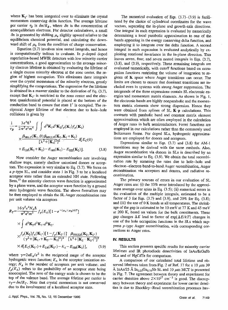
To further explore the effects of the valence band split- ting on the lifetime, consider the situation in which the split- ting AE, between the uppermost valence band HI31 and the next highest valence band H’ (LHl in the case of LAIR and VLWIR SLs) is greater than the band gap. The lifetime en- hancement resulting from reduced Auger recombination is illustrated in Fig. 6 for the case of an approximate model for the InAs/In,Ga,-,Sb SLs. The model assumes that the H’ band is flat in the in-plane direction, that there is no valence band with zero in-plane momentum exactly E, below the top of HHl, and that there is no K dependence of the transition matrix elements. Even though it only approximates the actual recombination physics, the model serves as a useful guide for examining the behavior of the lifetime as a function of the splitting of the valence bands and the energy gap. Figure 6 plots Q- as a function of both E, corresponding to 11 ,um or 0.114 eV and Al?,- E, (assumed to be positive). It demon- strates that the hole-hole Auger lifetime varies exponentially with AEv, the splitting between HI31 and H’. The lifetime is enhanced by approximately ten orders of magnitude if the splitting relative to the energy gap is increased from 0 to 0.15 eV, without changing the energy gap. Such a dramatic sup- pression may change hole-hole Auger recombination in the
7146 J. Appt. Phys., Vol. 78, No. 12, 15 December 1995 Grein et a/.
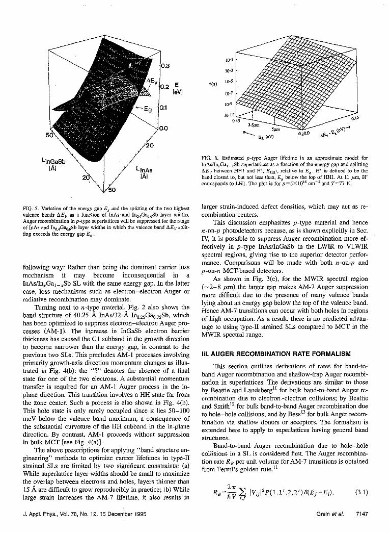
LlnA.s IA1
FIG. 5. Variation of the energy gap Es and the splitting of the two highest valence bands A& as a function of InAs’and Iq,4Ga&3b layer widths. Auger recombination in p-type superlatfices will be suppressed for the range of InAs and Ino,4Ga+eSb layer widths in which the valence band AE, split- ting exceeds the energy gap E, .
following way: Rather than being the dominant carrier loss mechanism it may become inconsequential in a InAslIn,Ga,-,Sb SL with the same energy gap. In the latter case, loss mechanisms such as electron-electron Auger or radiative recombination may dominate.
Turning next to n-type material, Fig. 2 also shows the band structure of 40.25 fL InAs A Ino,zsGa+,75Sb, which has been optimized to suppress electron-electron Auger pro- cesses (AM-l). The increase in InGaSb electron barrier thickness has caused the Cl subband in the growth direction to become narrower than the energy gap, in contrast to the previous two SLs. This precludes AM-l processes involving primarily growth-axis direction momentum changes as illus- trated in Fig. 4(b): the “?” denotes the absence of a final state for one of the two electrons. A substantial momentum transfer is required for an AM-l Auger process in the in- plane diiection. This transition involves a HH state far from the zone center. Such a process is also shown in Fig. 4(b). This hole state is only rarely occupied since it lies 50-100 meV below the valence band maximum, a consequence of the substantial curvature of the E&I-l subband in the in-plane direction. By contrast, AM-l proceeds without suppression in bulk MCT [see Fig. 4(a)].
The above prescriptions for applying “band structure en- gineering” methods to optimize carrier lifetimes in type-11 strained SLs are limited by two significant constraints: (a) While superlattice layer widths should be small to maximize the overlap between electrons and holes, layers thinner than 15 A are difficult to grow reproducibly in practice; (b) While large strain increases the AM-7 lifetime, it also results in
FIG. 6. Estimated p-type Auger lifetime in an approximate model for InAs/In,Ga, -,Sb superlattices as a function of the energy gap and splitting AEv between HHl and H’, E,t, relative to E, . H’ is defined to be the band closest to, but not less than, E, below the top of HHl. At 11 pm, H’ corresponds to LHl. The plot is for p=5X lOI cmW3 and T=77 K.
larger strain-induced defect densities, which may act as re- combination centers.
This discussion emphasizes p-type material and hence n-on-p photodetectors because, as is shown explicitly in Sec. IV, it is possible to suppress Auger recombination more ef- fectively in P-type InAs/InGaSb in the LWIR to VLWIR spectral regions, giving rise to the superior detector perfor- mance. Comparisons will be made with both n-on-p and p-on-n MCT-based detectors.
As shown in Fig. 3(c), for the MWIR spectral region (-2-8 ,um) the larger gap makes AM-7 Auger suppression more difficult due to the presence of many valence bands lying about an energy gap below the top of the valence band. Hence AM-7 transitions can occur with both holes in regions of high occupation. As a result, there is no predicted advan- tage to using type-II strained SLs compared to MCT in the MWIR spectral range.
III. AUGER RECOMBINATION RATE FORMALISM
This section outlines derivations of rates for band-to- band Auger recombination and shallow-trap Auger recombi- nation in superlattices. The derivations are similar to those by Beattie and Landsbergl’ for bulk band-to-band Auger re- combination due to electron-electron collisions; by Beattie and Smith’2 for bulk band-to-band Auger recombination due to hole-hole collisions; and by Bess13 for bulk Auger recom- bination via shallow donors or acceptors. The formalism is extended here to apply to superlattices having general band structures.
Band-to-band Auger recombination due to hole-hole collisions in a SL is considered first. The Auger recombina- tion rate R, per unit volume for AM-7 transitions is obtained from Fermi’s golden rule,‘l-
R =2” ~ IV,l”P(1,1’,2,2’jS(Ef-Ei), ’ tiv i,f
(3.1)
J. Appl. Phys., Vol. 78, No. 12, 15 December 1995 Grein et al. 7147

where V is the crystal volume; i denotes the initial states 1 and 2 as labeled in Fig. 3; f denotes the final states 1’ and 2’; V, is the matrix element of the screened Coulomb potential interaction between holes 1 and 2; P( 1,l ‘,a,?,‘) is a statistical weight function giving the occupation probabilities for the involved states; and Ei and Ef are the total energies of the initial and final states, respectively.
The matrix element Vif in Eq. (3.1) is expressed in terms of Slater determinant SL states as
Vif=
-4~hkPXrdAd e2 exp [-A[r,-i-,1]
h-l-4
(3.2) where AZ1=Ai2= 1 when holes 1 and 2 have the same spin; A2i=1 and A12=0 when holes 1 and 2 have opposite spin which is preserved in the transition; Azi=O and Atz= 1 when holes 1 and 2 have opposite spin which is changed in the transition; X is the reciprocal screening length, approximated by the Debye fornil X=(47~e*[n+p]l~kT)~“, where n and p are the electron and hole concentrations; and E is the static dielectric constant of the barrier layers. The SL wave func- tions are expanded in the (L,K) basis
I
q&(K,r)=(r(LK)= -& z CL(K,G)ei(KfG)‘r, (3.3)
where (K} and (G} are the sets of SL wave vectors and reciprocal lattice vectors, respectively.
After substituting Eq. (3.3) into Eq. (3.2), the integrals over rl and r, are performed analytically. Umklapp processes are neglected in the summations over the G’s. The neglect of Umklapp processes is a good approximation in Auger rate calculations for narrow gap bulk semiconductors’1~‘2*1s be- cause transitions occur near the zone center, resulting in only weak contributions from Umklapp processes. In narrow gap SLs the same argument applies to transitions with dominant in-plane crystal momentum changes. However, the neglect of Umklapp processes will result in more significant overesti- mates of lifetimes for transitions which primarily change the growth-axis crystal momentum, due to the short length of the Brillouin zone in that direction. In-plane crystal momentum changes dominate the Auger transitions in the superlattices discussed in Sec. V.
In analogy to the work of Antoncik and Landsberg,16 tirst-order SL K.p perturbation theory is employed to evalu- ate the overlaps of the SL wave function expansion coeffi- cients C,(K,G) at different points in K space. For example,
CE(Klf ,G)~(K,-K,~).ZG,C,(K~~ ,G’)pC&(KI, ,G’) &H(K,J)-EL(K~~)
,
where m is the free electron mass. This permits the square of the screened Coulomb matrix element to be expressed in terms of SL momentum matrix elements.
X S(K,-K,,+K,-K,,), (3.5)
where ,&Lt(K,K’)=I(L’K’[(K-K’).plLK’)(2/[EL(K’) -E1,~(K’>]2. The average over spins, involving summing over all possible terms involving different combinations of AiZ and A?,, has been approximated in a manner similar to that described by Sugimura,14 resulting in a possible error in lV,12 of ?33%. It is assumed in Eq. (3.5) that electron 2’ is in the LH band, but an equivalent expression remains correct if an electron in another valence band is involved instead.
The statistical weight function P(1,1’,2,2’) provides the appropriate weight for the net recombination, namely the dif- ference between Auger and impact ionization recombination rates. The Auger recombination rate is proportional to
f,(K,).f,(K~lf,(K,~)[l-.~~f,(Kz~)l, (3.6a)
and the impact ionization rate, its inverse process, is propor- tional to
7148 J. Appl. Phys., Vol. 78, No. 12, 15 December 1995
(3.4)
where f,, and .fP are electron and hole Fermi functions, re- spectively, with the corresponding quasichemical potentials f~+ and ph. Hence the net recombination rate is proportional to the difference of Eqs. (3.6a) and (3.6b),
XL1 -f,W24. (3.6~)
Energy conservation requires that electron 2’ be at least an energy gap below the top of the valence band. It is very improbable to find a hole this deep in the valence band, so 1 -fP (Ky ) is approximated by 1.
Inserting Eqs. (3.5) and (3.6~) into Eq. (3.1) yields
3e4Fi3 RB= 8T6E2m4 (1 -&Pe’~k)~kT)
x d3K2d3K,_lf,(Kl)f,(K22)f,(K1 + ~-KY) +I,~(K, ,K,+K,- K2r)~HH,LH(K2,K2r)
[h2+]K2,-K#]’
X flE&K1+K2-K2r)iELH(K2r)-Em(K1)
-4dK2j1, (3.7)
Grein et al.
where K,r has been integrated over to eliminate the crystal momentum conserving delta function. The average lifetime per carrier ?-B is 6nlRB, where Sn is the concentration of nonequilibrium electrons. For detector calculations, a small Sn is generated by shifting p,e sliglitly upward relative to the equilibrium chemical potential, and calculating the down- ward shift of & from the condition of charge conservation.
Equation (3.7) involves nine nested integrals, and hence is computationally tedious to evaluate. In p-doped doped superlattice-based MWIR detectors with low minority carrier concentrations, a good approximation to the average minor- ity electron lifetime is obtained by evaluating the lifetime of a single excess minority electron at the zone center, the re- gion of highest occupation. This eliminates three integrals over the crystal momentum of the minority electron, greatly simplifying the computations. The expression for the lifetime is obtained in a manner similar to the derivation of Eq. (3.7), except that K,! is restricted to the zone center and the elec- tron quasichemical potential is placed at the bottom of the conduction band to ensure that state 1’ is occupied. The re- ciprocal Auger lifetime of that electron due to hole-hole collisions is given by
‘ELH(KI~.K~)-EHH(KI)-EHH(K~)I. (3.8)
Now consider the Auger recombination rate involving shallow traps, namely shallow unionized donors or accep- tors. The expression is very similar to Eq. (3.7). We focus on a p-type SL, and consider state 1 in’Fig. 3 to be a localized acceptor state rather than an extended HH state. Following Bess,t3 the minority electron wave function is approximated by a plane wave, and the acceptor wave function by a ground state hydrogenic wave function. The above formalism may be then employed to obtain the SL Auger recombination rate per unit volume via acceptors
R T
= 16yse4N,h, n5E2m2 f,(E,)[ 1 -e-(PeTPk)lkT]
x d3K2d3Kltd3K2, I
~S[E,(K~~)+ELH(K~~>-E,-E,(K~)I, (3.9)
where y=2&,Je2 is the reciprocal range of the acceptor hydrogenic wave function; E, is the acceptor ionization en- ergy; NA is the number of acceptors per unit volume; and f,(E,) refers to the probability of an acceptor state being unoccupied. The zero of the energy scale is chosen to be the top of the valence band. The average lifetime per carrier is rT= &l/R,. Note that crystal momentum is not conserved due to the involvement of a localized acceptor state.
The numerical evaluation of Eqs. (3.7)-(3.9) is facili- tated by the choice of cylindrical coordinates for the wave vectors, separating the in-plane and growth-axis directions. One integral in each expression is evaluated by numerically determining a local parabolic approximation to one of the bands appearing in the energy conserving delta function, and employing it to integrate over the delta function. A second integral in each expression is evaluated analytically by ex- ploiting rotational invariance in the in-plane direction. This leaves seven, four, and seven nested integrals in Eqs. (3.7), (3.8). and (3.9), respectively. These remaining integrals are evaluated numerically, with cutoff functions based on occu- pation functions restricting the volume of integration to re- gions of K space where Auger transitions can occur. The limits are chosen to ensure that dominant transitions are in- cluded even in systems with strong Auger suppression. The integrands of the three expressions contain SL electronic en- ergies and momentum matrix elements. As shown in Fig. 1, the electronic bands are highly nonparabolic and the momen- tum matrix elements show strong dispersion. Hence they were obtained from splines of SL K.p calculations. This contrasts with parabolic band and constant matrix element approximations which are often employed in the calculation of Auger rates in bulk semiconductors. Fermi functions are employed in our calculations rather than the commonly used Boltzmann forms. For doped SLs, hydrogenic approxima- tions are employed for donors and acceptors.
Expressions similar to Eqs. (3.7) and (3.8) for AM-l transitions may be derived with the same methods. Also, Auger recombination via donors in SLs is described by an expression similar to Eq. (3.9). We obtain the total recombi- nation rate by summing the rates due to hole-hole and electron-electron band-to-band Auger recombination, Auger recombination via acceptors and donors, and radiative re- combination.
The primary sources of errors in our evaluation of SL Auger rates are: (i) the 33% error introduced by the approxi- mate average over spins in Eq. (3.5); (ii) numerical errors in the evaluation of the multiple integrals, estimated to be a factor of 3 for Eqs. (3.7) and (3.9), and 20% for Eq. (3.8); and (iii) the use of 0 K bands at all temperatures. The shrink- age of the gap is estimated to be 10 meV at 77 K and 45 meV at 200 K, based on values for the bulk constituents. These gap changes AE lead to factor of exp[AElkT] changes in one of the hole occupation functions in the SLs which sup- press p-type Auger recombination, with corresponding cor- rections to Auger rates.
IV. RESULTS
This section presents specific results for minority carrier lifetimes and IR photodiode detectivities of InAs/InGaSb SLs and of HgCdTe for comparison.
A comparison of our calculated total lifetime and ob- served lifetimes taken from Fig. 2 of Ref. 17 for a 10 ,um 39 A InAs. A Inaz5Gat,&b SL and 10 pm MCT is presented in ‘Fig. 7. The agreement between theory and experiment for carrier densities above 2X10i7 cmw3 is good. The discrep- ancy between theory and experiment for lower carrier densi- ties is due to Shockley-Read recombination processes hav-
J. Appl. Phys., Vol. 78, No. 12, 15 December 1995 Grein et a/. 7149

10-7t \ f
InAs-Gas.~sI~.&b SL
T=77K
**, Hgi-,Cd,Te
*\
;;y;; 1 , , , , , ,,,, “yy.;,;*, ,j , , ( , , ,,,, 1016 lo’a- 1017 10’8
n (cme3)
F[G. 7. Comparison of measured and calculated carrier lifetimes of a 39 A InAs/25 A Ina,Gaa$b superlattice (10 pm energy gap) as a function of carrier density (see Fig. 2 of Ref. 17).
ing a ~6x10~~ s which are not taken into account in the present calculations for ideal samples. These results are im- portant because they represent the first direct comparison be- tween theory and experiment for the systems considered here. They therefore provide confidence in the predictions made below. These results also confirm that SL carrier life- times in this system may be up to two orders of magnitude longer than in MCT with the same energy gap and carrier concentrations.
Total minority carrier lifetimes of the 11 ,um systems whose band structures have been discussed with Fig. 2 are shown in Fig. 8. The two p-type systems [Figs. 2(a) and 2(b)] have NA= lOI7 cm-3 and the n-type system [Fig. 2(c)] has ND= 1o17 cm-s. Minority carrier lifetimes for bulk HgCdTe with doping levels of NA= 1017 cmm3 and ND = lOi cme3 are also shown for comparison. These results are ob- tained by summing recombination rates due to band to band Auger processes, and those involving shallow traps, in addi- tion to radiative processes. The radiative lifetimes were cal- culated following Ref. 18. Radiative processes yield a life- time r,d -lop5 s for temperatures below about 100 K for lOI cm -3 doping for both SLs and MCT. Further, r,d goes approximately inversely as the majority carrier density, in contrast to the Auger lifetime which has an approximate in- verse square dependence. Comparison between the two 39.8/E SL 7)s corresponding to doping levels of lOI and 1Ol7 cme3 respectively, illustrate the dominant dependence on rrad for’T<lOO K. The increase of NA from 1015 to 1Or7 cme3 results in a corresponding two order of magnitude de- crease m Trad. By contrast, the decrease in r from -low5 to -lO-9 s in the two MCT samples shows that Auger pro- cesses are significant even in this low temperature range. The dominance of radiative recombination in the SLs considered here, arising -from Auger suppression, explains their rela- tively larger 7)s. Although it is not obvious from the calcu-
IO4
10”
2% .g 1o’7 al 5
10d
39.8/15 SL, N,=lO”cmJ - 39.8115 SL, N,=l O”cmJ ----- 40.25132 SL N =10’7cm3 - 41125 SL, Ni=12cmd ---- HgCdTe, N,=lO”cmJ --- HgCdTe, N,=lO’%nJ
lo* _------__ I --------_-__-_______________________ 1 O”O I I
5 7 9 11 13 15 1000/T(K)
FIG. 8. Calculated minority carrier lifetimes of 41 A InAs/ A InessGac7sSb (acceptor concentration 10t7. cme3), 39.8 A InAs/ A Ina4GaaaSb (acceptor concentration of 1OL7 cmw3), and 40.25 8, InAs/ 8, InO,,Gaa~,Sb (donor concentration ~of lOI cmm3) superlattices, and bulk Hga7aCd0,s,Te (donor concentration of 10” cm-‘) as a function of recipro- cal temperature.
lated temperature dependence, Auger processes dominate in the SLs above about 100 K. The overall behavior with tem- perature is determined by the distribution function of the carriers.
Lifetime gains due to Auger suppression in the SLs translate into improved detectivities D* shown in Fig. 9. The diffusion-limited specific detectivities obtained from the equations D * = ( 7/2/z v)( TJn.,L,) ‘I2 for n-on-p photo- diodes (P-type material), and D* = ( 77/2/z v) (~~lp~.L~) “’ for p-on-n photodiodes (n-type material)” are plotted versus 1000/Z’. Here 7 is the quantum efficiency given by $l,ppqz,pp+ * 17 ” where a is the absorption coefficient
1014 I
41/25 SL, N,=lO”cm” - 39.8/l 5 SL, N,=l Oi7cmJ ----- 40.2.5/32 SL, N,=10’7cm” --- HgCdTe, N,=lO”cm’ ---- HgCdTe, N,=lO”cm
i 5 7 9 11 13 15
1000/T(K)
FIG. 9. Calculated diffusion-limited detectivities D* for the four systems of Fig. 8 plotted as a function of reciprocal temperature.
7150 J. Appl. Phys., Vol. 78, No. 12, 15 December 1995 Grein et al.

lo4 N.4 0” cm4 j
i// //’ / .’
I/ I ’ - 13pm45/24SL
I’/ ~ 15 I.rm 47lZ6 SL
--- ---- 19 17 pm pm 50126 46130 SL SL 1
5 10 15 20 25 1 ooo/TK)
FIG. 10. Calculated minority carrier lifetimes of 13 pm 45 8, InAs/ A Iq&a,,,,$b, 15 pm 47 8, In&l26 fi I )&,,Sb,
1 17 pm 48 A InAs 8,
I~,Ga&Sb, and 19 ,um 50 A InAs/ In,-,,.,Ga+,$b, all with an acceptor concentration of IO” cm-‘, as a function of reciprocal temperature.
taken to be a=2000 cm-’ in the systems considered here. The minority carrier diffusion length, Lf,,p} = JG, is determined by the diffusion constant Df,,,j= (kT/e)p{,,p~, where ,q, = 1 X 10³ and ,up = 10 cm’/V s for the InAsiInGaSb SLs and is taken from experimentally determined values21 as a function of T and x for Hg,Cdti,Te. Note that LI,,~~ is proportional to rm so that D” is proportional to rt’4. Calcu- lated detectivities are theoretical upper bounds due to the neglect of other recombination mechanisms such as Shockley-Read. We find that intersubband absorption may be neglected due to the comparatively low carrier concentra- tions. The Arrhenius behavior of the curves results from the exponential dependence of D” on the minority density n,, 0: e-Es12kBT for n-on-p diodes. The value of D” at 1000/T =9, or 110 K, is a factor of 4.5 greater for the best SL as compared to the best HgCdTe sample shown in Pig. 9.
These improvements result from the lower minority car- rier concentrations present in the more heavily doped SL, which reduce the noise current. This effect outweighs the concomitant decrease in lifetime. In MCT by contrast the dominance of Auger recombination causes a far larger de crease in lifetime which is roughly the same for the same doping level, that outweighs the noise suppression.
Figure 10 examines the corresponding quantities for VL- WIR devices in the 13-19 ,um range. It shows the calculated total minority carrier lifetimes in 45 A InAs/24 A Inu~Ga,,$b with an energy gap of 13 pm, 47 A InAsl26 A In,,Gaa&3b with an energy gap of 15 pm, 48 A InAs/ 8, In,,G%,Sb with an energy gap of 17 pm, and 50 A InAs/28 A In,,G~$b with an energy gap of 19 pm, all doped with N A = lOI5 cmv3. Band-to-band Auger recombination suppres- sion again causes the radiative recombination to dominate the lifetimes for temperatures below about 100 K. The shal- low trap assisted Auger recombination rate is greater than the band to band processes in the narrower gap materials and is comparable to the radiative recombination rate because the phase space available for these processes is larger. The
J. Appl. Phys., Vol. 78, No. 12, 15 December 1995
1014
10IJ
-lo-
3 -g 10” E s
‘n 1o’O
loo
1O8
/.’ f.’
f A // // X.0 ,Y ---- - - --- 15 19 13 17 gm pm pm pm 50128 47126 45124 48130 SL SL SL SL
FIG 11. Calculated diffusion-limited detectivities D* for the four systems of Fig. 10 plotted as a function of reciprocal temperature.
steady decrease in the lifetimes with decreasing gap at fixed temperature is due to the increasing thermal carrier concen- trations. Note that Fig. 10 plots detectivities to lower tem- peratures in order to maintain a detectivity scale similar to that in Fig. 8. Diffusion-limited detectivities for n-on-p pho- rodiodes composed of these SLs are presented in Fig. 11. The D* s at 80 K vary between about 5X 101t and 5X 10” cm Hz”~/w with wavelength increasing from 13 to 19 pm. Since the band gap in type II SLs is determined by confinement energies as contrasted to chemical composition in bulk MCT, and since layer widths can be grown with very high accu- racy, it would appear that SLs of the sort discussed might well be uniquely qualified for this wavelength range.
V. SUMMARY
InAs/In,Ga, -,Sb SLs have been examined for potential infrared detector applications in the 1 l- 19 pm wavelength range. Band structure engineering methods are predicted to suppress band-to-band Auger recombination processes in both p- and n-doped material. Specifically, Auger rates are suppressed in p-type material by increasing the lattice mis- match through increasing x. The resulting strain splitting of the highest two valence bands limits available phase space for Auger transitions. By contrast, n-type materials are less advantageous because the Auger suppression achieved by in- creasing the In,GaI-,Sb layer widths, thereby flattening the lowest conduction band, is far less effective than the band structure adjustments possible in the valence bands. The sup- pression, particularly in the p-doped type-II superlattices, is large enough that these materials make better device candi- dates than HgCdTe in the long wavelength range (>ll pm).
ACKNOWLEDGMENTS
We are grateful to Richard H. Miles for many helpful discussions. This work was supported by the U.S. Advanced Research Projects Agency (ARPA) through the U.S. Office of Naval Research (ONR) Contract No. N00014-93-1-0549.
Grein et al. 7151

‘Y. Jiang, M. C. Teich, and W. I. Wang, Appl. Phys. Lett. 57, 2922 (1990). ‘Y. Bang, M. C. Teich, and W. I. Wang, J. Appl. Phys. 69, 6869 (1991). ‘C. Mailhiot and D. L. Smith, J. Vat. Sci. Technol. A7, 445 (1989). ‘D. H. Chow, R. H. Miles, J. N. Schulman, D.A. Collins, andT. C. McGill,
Semicond. Sci. Technol. 6, C47 (1991). ‘N. F. Johnson, H. Ehrenreich, P M. Hui, and I? M. Young, Phys. Rev. B
41, 3655 (1990). 6P. M. Young, Ph.D. thesis, Harvard University, 1993. ‘M. E. Flatte, P M. Young, L. H. Peng. and H. Ehrenreich (unpublished). *T. N. Casselman, I. Appl. Phys. 52, 848 (1981). 9A. R. Beattie, Semicond. Sci. Technol. 2, 281 (1987). The 0.4 ns lifetime
is an extrapolation from a doping level of 10” cmm3, based on the as- sumption that the Auger lifetime is inversely proportional to the square of the majority carrier density.
“P M. Young, C 7b, 4774 (1993).
H. Grein, IL Ehrenreich, and R. H. Miles, J. Appl. Phys.
‘t A. R. Beattie and P. T. Landsberg, Proc. R. Sot. London Ser. A 249, 16 (1959).
“A. R. Beattie and G. Smith, Phys. Status Solidi 19, 577 (1967). “L. Bess, Phys. Rev. 105, 1469 (1957). t4k Sugimura, J. Appl. Phys. 51, 4405 (1980).
7152 J. Appl. Phys., Vol. 78, No. 12, 15 December 1995
“P. T. Landsberg, Solid State Electron. 30, 1107 (1987). j6E. Antoncik and P. T. Landsberg, Proc. Phys. Sot. 82, 337 (1963). “E. R Youngdale et al., Appl. Phys. Lett. 64, 3160 (1994). ‘*C. IL Grein, P. M. Young, and H. Ehrenreich, J. Appl. Phys. 76, 1940
(1994). t9M. A. Kin& and S. R. Borrello, Infrared Phys. 15, 111 (1974). “OM. B. Reine, A. K. Sood, and T. I. Tredwell, in Semiconductors and
Semimetals, edited by R. K. Willardson and A. C. Beer (Academic, New York, 1981), Vol. 18, p. 201.
“M. W. Scott, J. Appl. Phys. 43, 1055 (1972). nSemiconductors: Group IV Elements and III-V Compounds, and Semicon-
ductors: Other than Group IV Elements and Ill-V Compounds, edited by 0. Madelung (Springer, New York, 1991).
23A. Blacha, H. Presting, and M. Cardona, Phys. Status Solidi B 126, 11 (1984).
%M. H. Weiler, in Semiconductors and Semimetals, edited by R. K. WiI- lardson and A. C. Beer (Academic, New York, 1981), Vol. 16.
‘jG. Bastard, Acta Electron. 25, 147 (1983). %R. Dornhaus and G. Nimtz, in Narrow-Gap Semiconductors, edited by G.
Hijhler (Springer, New York, 1983). “R. H Miles et al., Appl. Phys. Lett. 57, 801 (1990).
Grein et al.