Embed Size (px)
Citation preview

1
LOOKING FORWARD TO SOME NEW MISTAKES –
PLANNING THE SECOND NEWCASTLE – FASSIFERN RAILWAY
Garry Glazebrook
Figure 1: Non-streamlined Pacific 3830 departing Newcastle Station in 1966.
Photo: Robert Kingsford-Smith
1 Introduction
The Layout design Special Interest Group’s (LDSIG) motto is to “make only new mistakes”. This
seemed to me too good an invitation to turn down! So having got my first Newcastle – Fassifern
layout fully operational (though with the scenery and structures only 20% completed), I have begun
planning a bigger layout on which I could avoid the mistakes of the past, and create some new ones.
A previous article covered the planning of my first layout (LDJSIG journal no 47, Summer 2012;
http://www.ldsig.org/publications/journal). In addition, an article in the OPSIG journal (Vol XVIII No
3, July 2012, p27-33; www.opsig.org) described how I developed “compressed timetables” based on
the actual working timetables for the NSW railway in the Newcastle area in the mid 1960s.
Since then my wife and I have semi-retired and purchased “a small house with a large shed
attached” in the southern highlands, about an hour and a half south of Sydney. The rainfall patterns
and rich volcanic soil means you can grow almost anything – ideal for my wife’s gardening skills.
Nearby are wineries, beautiful beaches and mountains, not to mention the NSW Rail Steam
museum. What more could one wish for!

2
This article covers how I am approaching the design of my second layout. Although the article
follows the nice, logical approach outlined in the diagram on the left of Figure 2, the actual process
has been more like that on the right – a lot more intuitive, iterative and chaotic!
Figure 2: The Design Process
The article is arranged as follows:
Section 2 describes the lessons I learnt from my first layout
Section 3 covers some ideas drawn from other people’s layouts
Section 4 sets out the objectives, opportunities and constraints for my new layout
Section 5 develops the overall track scheme
Section 6 establishes the operating requirements and design standards
Section 7 details the layout design elements to be included
Section 8 develops six alternative design options which looked promising
Section 9 evaluates them against the objectives, and selects the preferred design
Section 10 discusses how I selectively compressed the Port Waratah-BHP steel mill complex
Section 11 presents some brief conclusions
Subsequent articles are planned to explore operational aspects in more detail, including:
Paperless Freight Car Forwarding
Signal and Point Control for one-man, small group and large operating sessions
Coal and freight train movements and servicing locomotives at Broadmeadow
3
2 Lessons from my First Layout
I think one can learn both from success and from failure. Might as well start with the good news!
Things that worked out as planned
My first layout has given me a lot of satisfaction, along with occasional headaches. I particularly
enjoyed designing the layout around a combination of “layout design elements” based on prototype
scenes, and an operations plan based on the actual train timetables which made the prototype such
an interesting place for rail fans in the 1960’s.
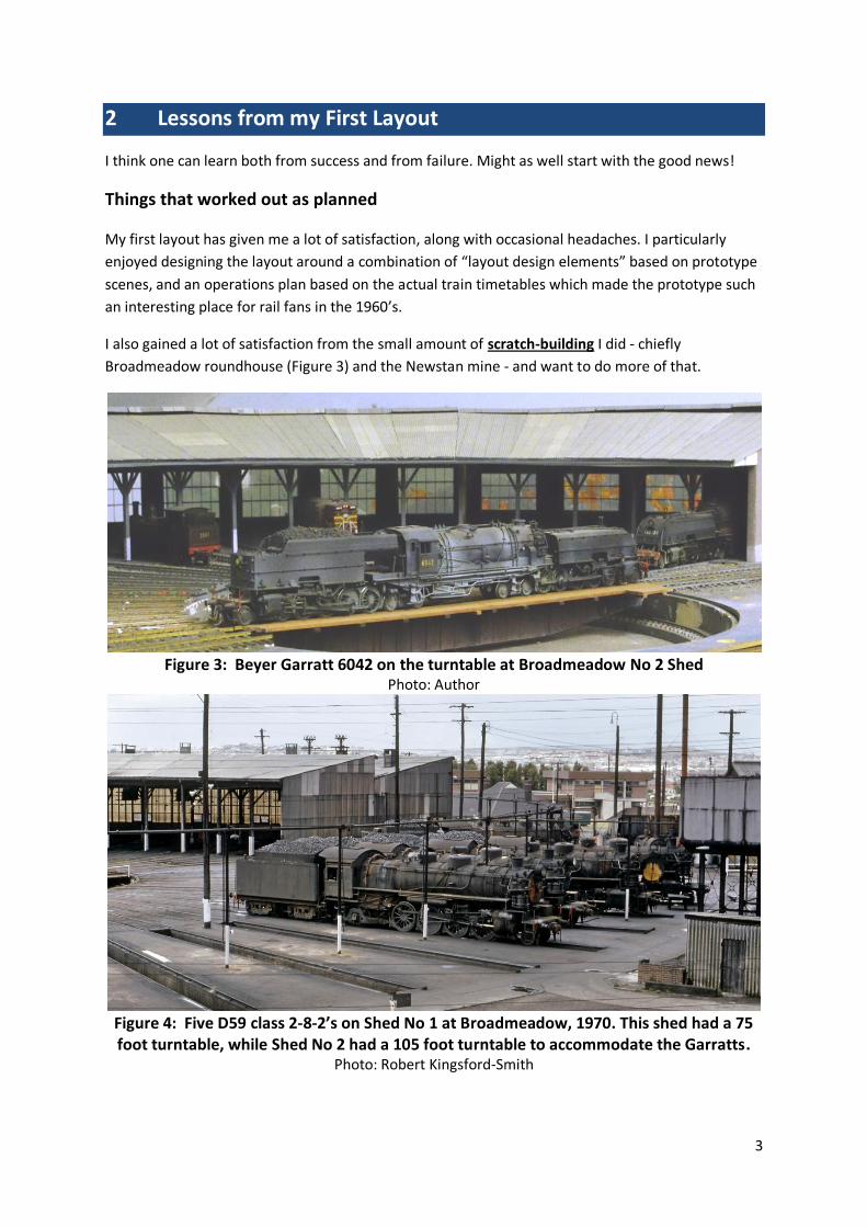
I also gained a lot of satisfaction from the small amount of scratch-building I did - chiefly
Broadmeadow roundhouse (Figure 3) and the Newstan mine - and want to do more of that.
Figure 3: Beyer Garratt 6042 on the turntable at Broadmeadow No 2 Shed
Photo: Author
Figure 4: Five D59 class 2-8-2’s on Shed No 1 at Broadmeadow, 1970. This shed had a 75 foot turntable, while Shed No 2 had a 105 foot turntable to accommodate the Garratts.
Photo: Robert Kingsford-Smith

4
The current layout height of about 1100 mm (44 inches) was governed by the sloping walls of the
attic and has worked reasonably well. Use of a variable height chair allows me to get to track level
for better viewing angles. However higher would be better.
When designing my first layout, I was particularly concerned at the difficulties of reaching the tracks
for construction and maintenance. In the end I was fairly satisfied with the level of access I managed
to achieve, using tricks like a hinged peninsula for Newcastle City and a lift up section at
Broadmeadow. Cleaning track and re-railing trains etc has proven to been manageable, although
there are still some places which are hard to reach.
More recently, I also really started to enjoy operating the layout with friends. This was actually
something I hadn’t really envisaged in the original design, but it got me more seriously into
operations. In particular, I developed a “selectively compressed” version of the actual working
timetable for 1965. I have also developed a car card system which manages to do away with waybills
but achieves the same results.
Figure 5: Operating Session on my current layout, August 2013
(Photos: Laurie Moses)
The author (right) and Laurie Moses during an operating session on the current Newcastle –
Fassifern Railway
Operations can be a lot of fun! Or at least Alistair Gilmour thinks so.
One of my colleagues, Marcus Amman, talked me early on into DCC using the NCE system. This has
also worked out very well (with his help). I found that DCC with wireless throttles enabled multiple
trains to be operated simultaneously, even on a small layout with complex trackage and junctions.
For example a four hour section of the timetable (see fig 6) between midday and 4pm includes
around 20 trains, not counting light engine movements, ranging from local and express passenger
trains to interstate and fast fruit express freights, steel freights, general freights, “pick-up” and “trip”
trains (local freights) and a variety of coal trains.
Three or even four trains are in operation simultaneously at times. This timetable has been run in
two actual hours with three – four operators. As might be imagined this gets pretty challenging in
such a small space (the layout room is 12 feet by 17 feet)!

5
Figure 6: Section of Timetable, 12 – 4pm
Things needing improvement
However there were also things about the current layout that are less than ideal, and which I
wanted to avoid in the new layout.
The chief limitation of the current layout is lack of space for operators. Three is really the desirable
limit, and even that is a squeeze. Since starting my first layout my circle of colleagues has expanded
(along with their waistlines). I wanted the new layout to be able to accommodate more people for
operating sessions, both for the social benefits and for the operating possibilities.
A second limitation is the short length of mainline run. The Newcastle Flyer takes only about 3-4
minutes of real time (9-12 minutes on the 3:1 timetable) to run from Newcastle to Sydney staging,
even when operated at fairly slow speeds. This is an inevitable limitation of a layout built in a small
attic (200 square feet), where the sloping walls precluded a double deck configuration.
The third problem has been unreliable operation. The complexity of the current track plan in such a
small space has necessitated very fine tolerances in terms of horizontal and vertical curvature, and
includes sections of track where both occur together. In addition, whilst my sub-roadbed system of a
sandwich of 3 mm medium density fibreboard, 10mm foam and 3 mm cork worked out well in terms
of being lightweight and sound absorbing, as well as allowing track to be pinned down, it has tended
to sag slightly over time and is not as rigid as one would like. Hence a lot of time has been spent in
fine-tuning the track, including making very small adjustments, to produce reliable operation. This
task is still not finished.

6
A fourth lesson was that I had perhaps sacrificed aisle widths too much in favour track space. This
creates problems for operators getting past each other without becoming too intimate! Physical
access becomes more and more important the older one gets, and getting under the layout to
install point motors or to maintain wiring has been a real issue at times.
My staging capacity, while reasonable, is still too tight. This means very careful design of the
timetable was necessary to ensure two trains don’t end up on the same track at the same time!
The final area needing improvement was the need for additional spaces other than for the layout
and operators. In particular I wanted:
a heavy workshop area screened from the main railway room so I could avoid covering
everything in dust every time I cut some timber
a crew lounge area; and
space for visitors to view the layout without getting in the way of operations.
The final consideration was comfort. Sydney has a very pleasant and mild climate, but things can
nevertheless get too hot in the Attic in summer. The Southern Highlands on the other hand can get
pretty cold in winter (at least for us wimps in Australia) with many nights below zero (Centigrade).
My new layout space would need both heating and possibly air conditioning, as well as excellent
lighting, carpets and other creature comforts.
3 Lessons from Other Layouts
As an avid reader of Model Railroader over the years, as well as Great Model Railroads, Model
Railroad Planning, specialist books on layout design and the OPSIG and LDSIG journals, I have
managed to pick up numerous tips over the years. Equally important have been the ideas, advice
and insights gleaned from my modelling colleagues in Australia as well as from some renowned
modellers I have been privileged to meet in the US. Here are some of the lessons I’ve picked up:
Staging
I think it was probably John Armstrong and Tony Koester who have done the most to highlight the
importance of staging and the many options available with the motto “you can never have enough
staging”. The only layout I’ve seen where this might seriously be challenged is David Parks’ amazing
“Cumberland West” layout, with 2,600 feet of hidden staging capable of storing 70 50-car trains!
While many people seem to have developed highly reliable hidden staging systems with videos or
track occupancy devices to keep track of the trains I decided it was desirable to keep my staging as
easily accessible as possible, in part to allow easy swapping in and out of steel, timber and other
“visible” loads. I also decided to use reversing loops to enable trains to enter staging and then return
without having to back up or to swap locos or brake vans (cabooses). This is important given that
some trains will be used more than once in a six hour (two hour real time) operating session.
Scenery and Imagination
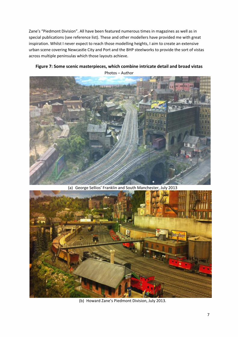
I love urban scenes, and have been lucky to see some of the greatest scenic models ever built,
including George Sellios’ “Franklin and South Manchester”, John Pryke’s “New Haven” and Howard
7
Zane’s “Piedmont Division”. All have been featured numerous times in magazines as well as in
special publications (see reference list). These and other modellers have provided me with great
inspiration. Whilst I never expect to reach those modelling heights, I aim to create an extensive
urban scene covering Newcastle City and Port and the BHP steelworks to provide the sort of vistas
across multiple peninsulas which those layouts achieve.
Figure 7: Some scenic masterpieces, which combine intricate detail and broad vistas
Photos – Author
(a) George Sellios’ Franklin and South Manchester, July 2013
(b) Howard Zane’s Piedmont Division, July 2013.

8
Layout height, depth and backdrops
Having seen some layouts with benchwork which is 1.3 metres (52 inches) or more above ground, I
decided that this adds greatly to realism whilst also making it easier to get under the layout during
construction or maintenance. This also means backdrops and narrow shelves can be much more
effective. A great example is Pelle Soeberg’s Daneville layout (Soeberg, 2012) which achieves
unbelievable realism even with narrow desert scenes.
Aisle Widths and other Parameters
My own layout proved the limitations of narrow aisles. But how wide need they be? Experience
operating on other layouts suggests 90 cm (36 inches) or more is desirable to allow operators to pass
easily, although 80 cm can be wide enough for short distances. Where there is definitely one-way
traffic, “pinch points” can be 60 cm (2 feet) or even less provided there are no easily breakable
scenery items on the edge. Some modellers have decided to err on the side of generosity with aisle
widths – one layout I visited recently was Dan Vandermaus’s “S” gauge B&O layout, where he
deliberately decided to keep the track plan simple to allow lots of space for operators, making it a
delight to run trains. The Model Railway Club layout in Union, New Jersey, goes one step further in
providing extensive high level aisles purely for visitors.
Figure 8: Space for Operators and Visitors is a key consideration
Photo: Author
The author’s wife, Heather, operating on Dan
Vandermause’s layout, July 2013 View of the MRC Layout from elevated visitor aisles. New extensions in foreground. July 2013
One thing I was worried about when designing my first layout was curve radius. I was forced to use
curves as small as 65 cm (26 inches) on the mainline, and I expected this to be a visual if not an
operational problem. However I discovered that NSW prototype rolling stock can usually negotiate
such curves and while much wider curves certainly look much better they aren’t essential if
superelevation and transition curves are used. I therefore settled on 70 cm (28 inches) as the
minimum radius for visible mainline track, with 75 cm (30 inches) preferable, together with
transition curves wherever possible.
Operations

9
I have operated on a number of larger layouts in Australia, including Marcus Ammann’s Short North
(http://www.members.optusnet.com.au/nswmn/) and Alistair Gilmore’s ambitious Junee layout.
Both of these are large-scale home layouts of around 600 – 1,000 square feet based on the NSW
prototype and capable of handling eight or more operators.
I have also been lucky enough to attend operating sessions on a number of US layouts, including the
Model Railroad Club layout in Union, New Jersey, Seth Neumann’s layout in the San Jose area, and
twice on David Parks’ Cumberland West layout, where up to 20 operators operate a complex
timetable with a despatcher, staging manager, tower operators, road and yard crews (indeed I
believe David recently had a joint B&O / Western Maryland operating session with 30 operators!).
These experiences highlighted the fun and comradeship to be had from successfully simulating
prototypical operations on large, complex layouts. They also underline the level of investment
required to achieve reliability and realism, both in track, equipment, signalling (if game enough) and
timetabling. My new layout is therefore designed to try to emulate the operating fun of some of
these layouts.
Figure 9: Operations on Large Layouts
(All Photos by Author)
Operating Session (Western Maryland) at David
Parks’ Cumberland West Layout – July 2013. Operating Session at Alistair Gilmore’s Main
South Layout, Sydney, September 2013
4 Objectives, Opportunities and Constraints
Key Objectives
Unlike some modellers who choose entirely new themes for their second or subsequent layouts, I
simply decided to build a bigger and hopefully better version of the first layout. I am reassured by
Pelle Soeberg’s recent book on “Rebuilding a Layout from A to Z” that I am not completely insane, or
at least that the jury is still out!
My overall aim is simply to indulge in more planning, building and operating, all of which I enjoy.
However I also wanted multi-person operations and more industrial landscapes such as steelworks
and port areas. My key design goals for Layout No 2 are set out below:

10
Figure 10: Key Objectives
Opportunities and Constraints
The new space is a solid steel frame shed on a concrete base, approximately 9.8 by 7.2 metres
internally (32 feet by 23 feet). This is large enough to do some serious damage, not least to the
wallet! The shed has two roller doors for car access, and a side door. There are no internal pillars. So
far this is looking perfect!
However there is one serious constraint – my wife wants the shed to actually double as a garage! I
know this will strike you as entirely unreasonable, and indeed most of my rail buddies have
expressed similar views. But real life always involves some constraints, and I find the layout design
exercise much more meaningful and satisfying when there are some constraints to overcome.
Figure 11: Opportunities and Constraints
(a) The shed, from the house
(b) Options for car
11
There are two basic options for the car space - on the right front or the left front as you face the
shed (See figure 11). Either option would eat up around a quarter of the space available for the
layout, leaving approximately 580 sq ft (52 sq m), or almost 3 times the space for my existing layout
which is 204 sq ft (17 feet by 12).
However I realised that including the car might not be the problem I thought it would be, because it
opens up possibilities for multiple use of the car space as a workshop and also as a crew lounge. In
addition, raising the layout height opens up the possibility of having part of the layout and / or a
workbench above the bonnet of the car.
Fitting the layout around the car means careful thought had to be given to the actual dimensions of
the car. I’ve always wanted to own a 2010 Subaru outback, so its dimensions were carefully
calculated and this turned out to be critical to the viability of potential designs, as will become
clearer later. We usually keep our cars for 15 years or so, which is the expected lifespan of this
project, so as long as we keep doing that there is no problem! Alternatively the layout will be the
constraint on any future car purchase, a nice twist on the current situation.
I think layout design always involves tradeoffs between operational, aesthetic and practical
considerations, even when this is not always evident. The balance between these objectives will
depend on your preferences – are you operationally driven and quite happy with running trains on
“plywood central”; are you more interested in aesthetics, wanting to create believable scenes to
recreate your memories of the prototype; or are you a practical kind of guy who enjoys it when
things actually work?
In my case I was equally driven by operations and aesthetics in designing my first layout, but hadn’t
fully considered some of the practical aspects. So for the next layout I’m aiming to give equal
balance to all three areas.
The design process then becomes trying to achieve the best overall compromise between what can
sometimes be conflicting objectives, within the space and other constraints. I find the challenge of
doing this a real source of satisfaction.
5 Overall Track Scheme
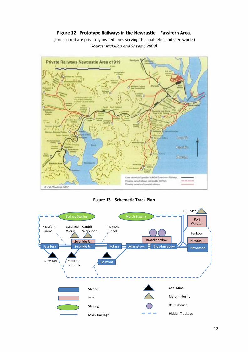
The area to be modelled was the same as for the previous layout - see Figure 12 below. The track
scheme is directly based on the prototype with selective compression. Quite a few stations were left
out, but the order of the stations modelled was the same as in reality, as was the relative location of
key elements such as the climb up to Tickhole tunnel from both Sulphide Junction and from Kotara.
The two main changes from the first layout were the addition of Port Waratah and BHP steelworks,
and the addition of the Belmont branch line. This line was one of many private coal lines in the
Newcastle region serving the dozens of mostly underground mines which infested the area. Indeed
most of Newcastle and its suburbs lie on top of coal deposits, and are affected by subsidence.
12
Figure 12 Prototype Railways in the Newcastle – Fassifern Area.
(Lines in red are privately owned lines serving the coalfields and steelworks)
Source: McKillop and Sheedy, 2008)
Figure 13 Schematic Track Plan

13
6 Operating Requirements and Standards
Staging and Track Capacity
In addition to the key visible parts of the layout, I needed a number of staging tracks to support
operation. Conceptually these were divided between:
“Sydney Staging” south of Fassifern
“North Staging” representing everywhere north of Islington Junction, which is where the
branch to Port Waratah comes off the main line
Staging tracks for the Belmont Branch, of which only a short section would actually be
modelled, as well as staging tracks representing the Stockton Borehole mine.
As with the previous layout, I plan to operate on a “loads in – empties out” basis for coal trains.
Hence the mines at Newstan, Stockton Borehole and Belmont branch needed to be connected via
hidden track to Port Waratah, which in the prototype is where loaded coal trains terminated (see
figure 13). Port Waratah thus needed to operate as a “through” destination rather than as a
terminus. This meant that the Port Waratah LDE if located on a peninsula would need to include a
loop track. As it turned out, this is ideal for accommodating the BHP steel works within the loop, as
will emerge in the detailed designs.
Newcastle would continue to be operated as per the prototype – as a terminus, since it handled
mostly passenger trains, and since I wanted to include the light engine movements between
Newcastle and Broadmeadow loco depot. This meant that Newcastle LDE could be accommodated
on a peninsula.
The design of the main staging tracks for “Sydney Staging” and “North Staging” proved difficult.
Ideally I wanted both to be double-ended with a return loop. This would allow trains entering
Sydney Staging, representing trains headed for Sydney or points south, to be automatically turned
and ready to return to Newcastle. This was particularly important since these trains were mostly
hauled by steam locos, rather than diesels, and I wanted to avoid use of a hidden turntable to turn
the locos if possible. On the other hand most trains headed for North Staging were diesel hauled by
the mid 1960’s making it easier for them to be turned; hence a return loop for North Staging was not
as important. One final option was to link North Staging and Sydney Staging. This would allow trains
to operate continuously in a clockwise (southbound) or anti-clockwise (northbound) direction,
obviating the need to turn engines etc. Whilst useful for some operations, this is less like the
prototype, and I decided this was not essential.
Finally I estimated I needed a total of around 43-45 staging and “on-layout” tracks to accommodate
my expected rolling-stock fleet of 32 train “sets”, including:
10 passenger trains (two long distance air-conditioned train sets; one long distance mail
train; one “Newcastle Flyer” set; three sets for Newcastle – Gosford and Newcastle –
Maitland services; and two 3 to 5 car sets plus one two-car diesel-hydraulic set for local
suburban services from Newcastle to Toronto and Belmont.

14
10 “unit” coal trains (four bogie hopper sets for Newstan Mine – Port Waratah and Wangi
Power station services; four 4-wheel sets for Belmont – BHP and Stockton Borehole – Port
Waratah services; and two steel hopper BHP sets for dedicated coking coal traffic to BHP)
Around 12 freight train “sets” including Interstate Express, Fast Fruit Express, Fast Livestock,
Steel train, Ore train, General Freight trains, “Pick up” and local “Trip” trains.
Standards
In addition to considering the track schema, LDE’s and operational issues it is also important to set
out the standards to be used. In this case, experience with my first layout has proved invaluable. For
example I also discovered that my two “Eureka” Garratts could just handle a train of 17 coal hoppers
loaded with real coal, plus brake van (as we call them) on the 2.5% Fassifern Bank – the same as the
prototype (these trains weight 1200 tonnes (1320 US tons) excluding the Garratts which added a
further 520 tonnes (570 US tons).
So my train lengths and maximum gradients would remain the same as in my first layout. This helped
govern the design of yards and passing tracks. Actual gradients used on the visible parts of the layout
will be the same as on the prototype. However I decided that vertical curves should occur on straight
sections of track wherever possible.
My current layout had used Peco Code 100 and Code 75 track, but I wanted to move to Code 83 and
Code 70 track for the new layout, since it is closer to the prototype and because there is such a wide
range of points available in Walthers (Shinohara), including curved points, double slips etc. Much as
the idea of hand laid track appeals, there are 200 points on the new layout!
Table 1: Standards for the New Layout
Minimum Radius Minimum Aisle widths
Hidden Track 65 cm (26 inches) one way “pinch point” 55 cm (22 inches)
Visible Branchline 70 cm (28 inches) one-way aisle 60 cm (30 inches)
Visible Mainline 75 cm (30 inches) two way “pinch point” 80 cm (32 inches)
Points (Turnouts) two way aisle 90 cm (36 inches)
Mainline No 6 Other Dimensions
Yards, Industrial No 5 Main Layout height 1.3 m (52 inches)
Maximum Gradient 2.5% (1 in 40) Max reach from edge 80 cm (32 inches)
Maximum Train Length 3.5 m (12 feet)
7 Layout Design Elements
As with the previous layout, I wanted to include a number of key layout design elements:
Newcastle station, city centre and port
Broadmeadow yard, station and locomotive terminal (with two roundhouses)
The climb up to Tickhole tunnel and down to Sulphide Junction
The Sulphide Junction / Cockle Creek area, including the Cardiff Workshops, the Sulphide
Works and branch line to Stockton Borehole colliery

15
Fassifern and the branch to Newstan colliery
The Belmont branch with the Belmont colliery (a new element).
Port Waratah and BHP Steelworks (a new element)
Newcastle Station, City Centre and Port
This layout design element had already been included in my current layout. My main objectives for
the new layout were to include:
slightly longer platforms at Newcastle to allow full length trains to operate (See Fig. 1)
a larger city centre at Newcastle, in particular to include the Catholic Cathedral.
an expanded port area and associated freight yard at Civic.
Figure 14: “Standard Goods” 2-8-0 no 5133 has just arrived at Civic Yard from
Broadmeadow on a “Trip Train” or local freight.
Photo: Robert Kingsford-Smith
Fortunately the compact nature of the prototype, where the main line runs very close to the Hunter
River and Newcastle Port (see Figure 14), and where Newcastle station is sandwiched between the
City Centre and the River (See Figure 1), means that it is possible to model the area in a finite space
whilst keeping many of the geometries similar to the real thing. This in fact is one of the key
attractions of the area from a modelling perspective.
Broadmeadow Yard, Station and Locomotive Depot
Again, these had been included in the existing layout. However I wanted the new LDE to be closer to
the prototype, in particular to include:
both roundhouses
16
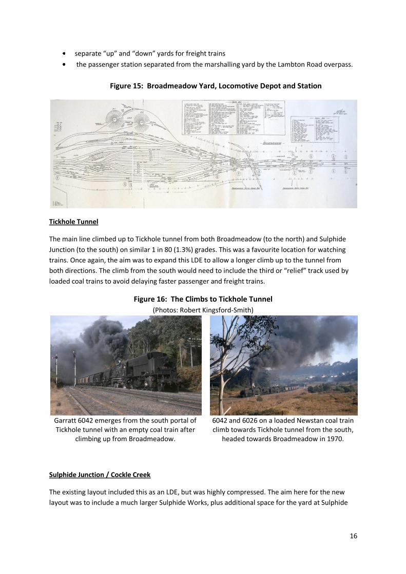
separate “up” and “down” yards for freight trains
the passenger station separated from the marshalling yard by the Lambton Road overpass.
Figure 15: Broadmeadow Yard, Locomotive Depot and Station
Tickhole Tunnel
The main line climbed up to Tickhole tunnel from both Broadmeadow (to the north) and Sulphide
Junction (to the south) on similar 1 in 80 (1.3%) grades. This was a favourite location for watching
trains. Once again, the aim was to expand this LDE to allow a longer climb up to the tunnel from
both directions. The climb from the south would need to include the third or “relief” track used by
loaded coal trains to avoid delaying faster passenger and freight trains.
Figure 16: The Climbs to Tickhole Tunnel
(Photos: Robert Kingsford-Smith)
Garratt 6042 emerges from the south portal of Tickhole tunnel with an empty coal train after
climbing up from Broadmeadow.
6042 and 6026 on a loaded Newstan coal train climb towards Tickhole tunnel from the south,
headed towards Broadmeadow in 1970.
Sulphide Junction / Cockle Creek
The existing layout included this as an LDE, but was highly compressed. The aim here for the new
layout was to include a much larger Sulphide Works, plus additional space for the yard at Sulphide

17
Junction and the branch leading from Cockle Creek across the creek to Stockton Borehole and other
coal mines.
Figure 17: Scenes near Sulphide Junction
5920 at Sulphide Junction, 1972. (Photo: Robert Kingsford-Smith)
5408 plus 6042 double-head a general freight train in 1972, north of Sulphide Junction. (Photo: Robert
Kingsford-Smith)
Figure 18: Sulphide Junction Track Plan
Newstan Colliery and Fassifern Bank
These were key “signature elements”, as explained in the article on the first layout, but had been
highly compressed in my current layout.
The actual arrangements at Fassifern as they were in the 1960’s are shown in Figures 9, showing the
branch to Toronto served by diesel railmotors and local passenger trains powered by C30 4-6-4 tank
locomotives, as well as the branch to Newstan Colliery. Empty coal trains arrived at Fassifern from
Port Waratah and then backed into Newstan; loaded coal trains backed out onto the main line from
the Newstan branch, then propelled forwards up the bank. The Newstan mine had a three track
yard, a large overhead coal bin for loading trains, a range of administrative, workshop, pit head and
other structures which all make great modelling subjects.

18
Figure 19 Newstan Mine track arrangements, 1960’s
Source: Attenborough (2002)
Figures 20 and 21 show scenes at Newstan and the top of the Fassifern bank
Figure 20 Garratts at Newstan Colliery Figure 21 Garratt on empty coal train at top of Fassifern Bank
Source: Attenborough (2004) Source: Attenborough (2004)
I therefore wanted the new layout to include a much better representation of this area, specifically:
Fassifern station, including the curved platform for the Toronto Branch
A longer Fassifern Bank, including the signature cutting at the top of the bank
More visible trackage and space for buildings at Newstan Colliery (coal mine), as well as
hidden tracks connecting the mine to Port Waratah. The aim was for an empty coal train to
back under the coal loading bins to the hidden track, where it would be replaced by a loaded
coal train which had been forwarded from Port Waratah via the hidden staging track (see
figure 13).
Belmont Branch
As shown on Figure 12 there were a number of privately owned branch railways operating in the
Newcastle area. One of these was the Belmont branch, which headed south from Adamstown just
19
south of Broadmeadow, and served a number of collieries which provided coking coal for the BHP
steel works. In the mid 1960’s, the line generated a significant number of coal trains of 4-wheel
hopper cars mainly hauled by “Standard Goods” locomotives, together with a few suburban
passenger trains hauled by 4-6-4 tank locomotives. From the mid 1960’s coal traffic began to be
taken over by 48-class light weight Co-Co diesel electric locos, bogie steel hopper wagons were
introduced, and passenger traffic declined.
Modelling this single line coal branch would therefore provide additional variety in operations, and
would be a new element as it wasn’t included in the current layout.
However space was expected to be limited, so I decided to include only one station and coal mine on
the route, with the remainder of the line represented by staging.
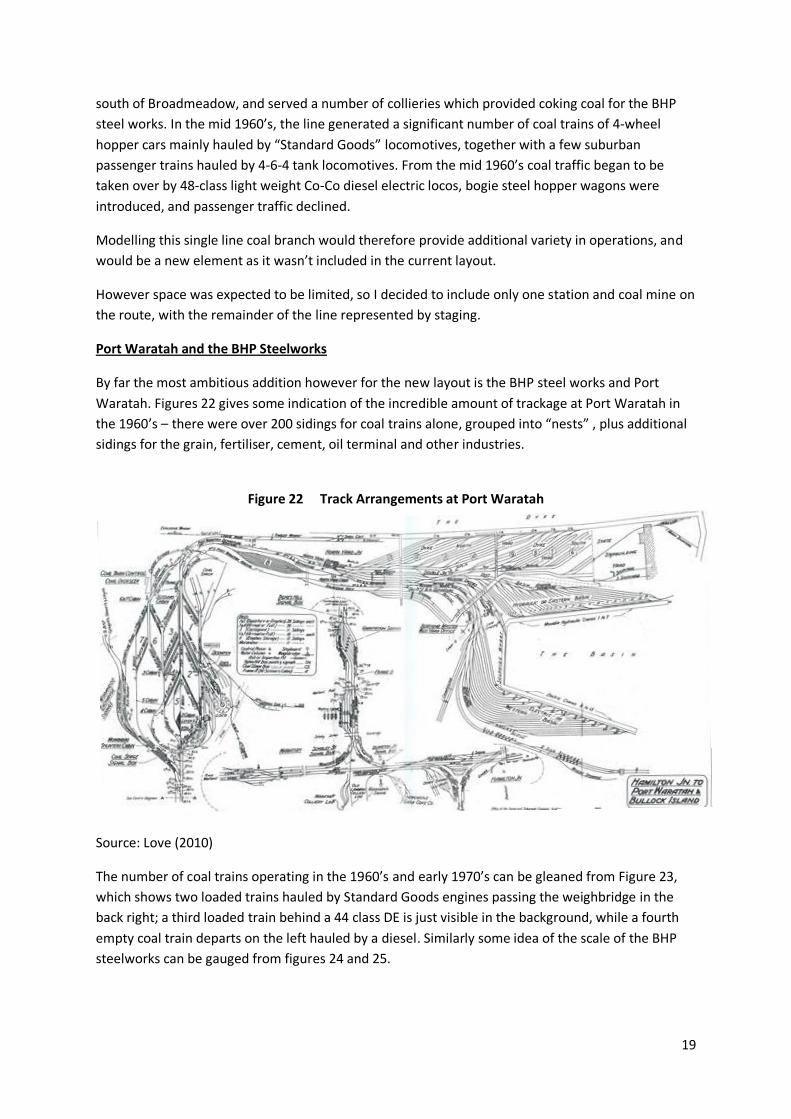
Port Waratah and the BHP Steelworks
By far the most ambitious addition however for the new layout is the BHP steel works and Port
Waratah. Figures 22 gives some indication of the incredible amount of trackage at Port Waratah in
the 1960’s – there were over 200 sidings for coal trains alone, grouped into “nests” , plus additional
sidings for the grain, fertiliser, cement, oil terminal and other industries.
Figure 22 Track Arrangements at Port Waratah
Source: Love (2010)
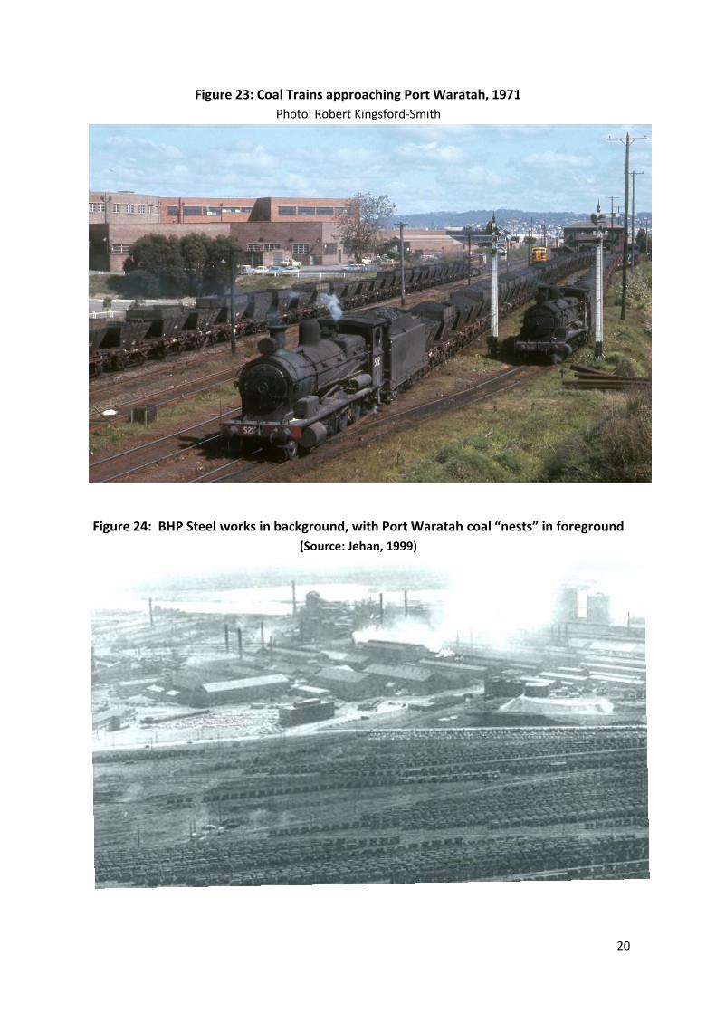
The number of coal trains operating in the 1960’s and early 1970’s can be gleaned from Figure 23,
which shows two loaded trains hauled by Standard Goods engines passing the weighbridge in the
back right; a third loaded train behind a 44 class DE is just visible in the background, while a fourth
empty coal train departs on the left hauled by a diesel. Similarly some idea of the scale of the BHP
steelworks can be gauged from figures 24 and 25.
20
Figure 23: Coal Trains approaching Port Waratah, 1971
Photo: Robert Kingsford-Smith
Figure 24: BHP Steel works in background, with Port Waratah coal “nests” in foreground
(Source: Jehan, 1999)
21
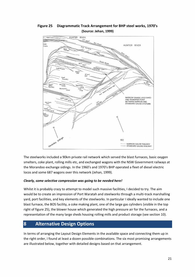
Figure 25 Diagrammatic Track Arrangement for BHP steel works, 1970’s
(Source: Jehan, 1999)
The steelworks included a 90km private rail network which served the blast furnaces, basic oxygen
smelters, coke plant, rolling mills etc, and exchanged wagons with the NSW Government railways at
the Morandoo exchange sidings. In the 1960’s and 1970’s BHP operated a fleet of diesel electric
locos and some 687 wagons over this network (Jehan, 1999).
Clearly, some selective compression was going to be needed here!
Whilst it is probably crazy to attempt to model such massive facilities, I decided to try. The aim
would be to create an impression of Port Waratah and steelworks through a multi-track marshalling
yard, port facilities, and key elements of the steelworks. In particular I ideally wanted to include one
blast furnace, the BOS facility, a coke making plant, one of the large gas cylinders (visible in the top
right of figure 25), the blower house which generated the high pressure air for the furnaces, and a
representation of the many large sheds housing rolling mills and product storage (see section 10).
8 Alternative Design Options
In terms of arranging the Layout Design Elements in the available space and connecting them up in
the right order, I found at least a dozen possible combinations. The six most promising arrangements
are illustrated below, together with detailed designs based on that arrangement.

22
Option 1
Figure 26(a): Option 1 Concept
This was one of my early designs, with the car space (and workshop) on the right hand side facing the garage doors (top right of diagram). Access to the layout is from the garage via a lift up / drop down section containing Adamstown station. Broadmeadow runs along the lower side, eliminating the side door and one of the two garage doors. Newcastle and Port Waratah are on peninsulas, with the harbour between them on a drop down section to create an aisle for additional access. The main staging is open on the left hand wall. Sulphide Junction and the workbench are located above the bonnet of the car.
Figure 26(b): Option 1 Detailed Design

23
Option 2
Figure 27(a): Option 2 Concept
This option switches the car space and garage to the lower right (i.e. left hand garage door), allowing the side door to the shed to be used. Broadmeadow is now on a diagonal, with the locomotive depot over the bonnet of the car, and somewhat restricted space for the car’s front door to be opened. Overall run length is less than option A, but aisle space is somewhat less restricted. The garage doubles as a visitor space / crew lounge area. The north staging is open (on the left hand wall) but the Sydney staging tracks are under the Newcastle peninsula or alternatively under Broadmeadow.
Figure 27(b): Option 2 Detailed Design

24
Option 3
Figure 28(a): Option 3 Concept
Option 3 is an entirely different design. While the car is in the same location as for Option 2, Broadmeadow is shifted to be along the top wall, Newcastle and Port Waratah are shifted, and the main staging is now located under the steelworks building (this is designed as a tall shed, with an open side facing the car space, allowing access underneath to the tracks, which are mostly at a level below the tracks in Port Waratah). There is space for a long peninsula on the left, enabling a long run for the main line. Access to the layout is via the garage door, with a removable section of track adjacent to the roller door. The side door to the shed is no longer usable, and there is no workbench.
Figure 28(b): Option 3 Detailed Design

25
Option 4
Figure 29(a): Option 4 Concept
This is yet another quite different layout. Broadmeadow has been shifted to the middle of the shed, and the main staging to the lower wall (with hinged reversing loops which drop down when the car is removed). Port Waratah and the steelworks are now along the back wall rather than on a peninsula. This arrangement reproduces the two triangle junctions between Broadmeadow and Port Waratah. However it requires some compression of Broadmeadow. Access to the main operating areas is somewhat difficult, and two lift up / drop down sections would be needed. The bench work would have to be very high to enable the second roundhouse to be above the car’s front windscreen.
Figure 29(b): Option 4 Detailed Design

26
Option 5
Figure 30(a): Option 5 Concept
This option is a variant of Option 2, with some subtle changes to the design of Broadmeadow by re-arranging the tracks between there and Sulphide Junction. There is now ample space for both Newcastle and Port Waratah and more space for Broadmeadow with a more prototypical track arrangement. This also includes a longer mainline run than Option 2 but retains the open staging for the north staging yard, with Sydney staging under Newcastle. As with most of the other options, the drop-down Newcastle harbour allows access when required to the tracks at Port Waratah and Newcastle Port. If necessary, the layout can be operated with the car still in the garage.
Figure 30(b): Option 5 Detailed Design

27
Option 6
Figure 31(a): Option 6 Concept
The final option is similar to Option 5, but switches the car space back to the right hand door (but not the workshop). This allows a long main line run with a longer peninsula, allowing an extra station (Cardiff) to be included. However it requires a 2.7 m long section of the layout behind the roller door to be removable in order for the car to enter the garage. The car would have to be removed to allow operations. Whilst producing significant operator space, the workshop area and visitor space is somewhat cramped.
Figure 31(b): Option 6 Detailed Design

28
9 Selecting the Best Design
Choosing the “best” design is always ultimately a subjective process. However I found it useful to
attempt to undertake a semi “rational” analysis based on the objectives identified earlier.
Accordingly, I converted these into criteria and measures, evaluated each of the six options based on
these, and then gave a score for each option. I then calculated the total weighted score for each
option based on operational, aesthetic and practical criteria, as suggested by one of my colleagues,
Derek Cullen.
In some cases it was possible to use objective measures, such as the length of mainline run or the
number of staging tracks. In others, particularly for the aesthetic criteria, I simply scored each of the
options out of 10, with my favourite option given a score of 10. In doing this I considered such
aspects as how closely the track plan followed the prototype in terms of location and the direction of
curves. For example:
- the climb up to Tickhole tunnel, where I did some of my train watching as a youth, has a
particular resonance and so trying to achieve the “feel” of this area was important.
- Similarly it was important to include the curve at the top of Fassifern Bank, where the
Garratts struggled over the last part of the climb, and to have enough space to replicate the
deep sandstone cutting at that location.
- Newcastle station was also a key element, and all options aimed to get a reasonably faithful
representation of the tracks and platforms in this location.
- Finally Broadmeadow was also a key aesthetic element, especially the relationships between
the passenger station, the marshalling yard and the locomotive roundhouses.
The table and graph below shows my how I assessed the design options against my own criteria.
Figure 32: Comparison of the Options
29
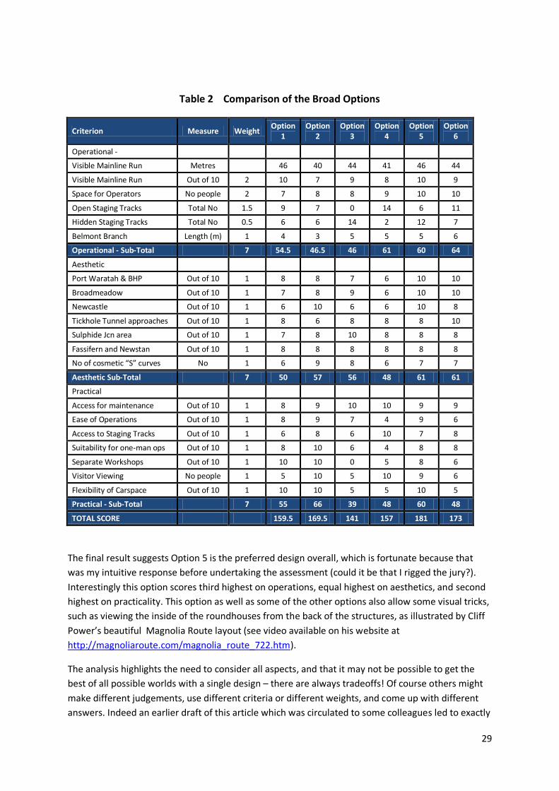
Table 2 Comparison of the Broad Options
Criterion Measure Weight Option
1 Option
2 Option
3 Option
4 Option
5 Option
6
Operational -
Visible Mainline Run Metres 46 40 44 41 46 44
Visible Mainline Run Out of 10 2 10 7 9 8 10 9
Space for Operators No people 2 7 8 8 9 10 10
Open Staging Tracks Total No 1.5 9 7 0 14 6 11
Hidden Staging Tracks Total No 0.5 6 6 14 2 12 7
Belmont Branch Length (m) 1 4 3 5 5 5 6
Operational - Sub-Total 7 54.5 46.5 46 61 60 64
Aesthetic
Port Waratah & BHP Out of 10 1 8 8 7 6 10 10
Broadmeadow Out of 10 1 7 8 9 6 10 10
Newcastle Out of 10 1 6 10 6 6 10 8
Tickhole Tunnel approaches Out of 10 1 8 6 8 8 8 10
Sulphide Jcn area Out of 10 1 7 8 10 8 8 8
Fassifern and Newstan Out of 10 1 8 8 8 8 8 8
No of cosmetic “S” curves No 1 6 9 8 6 7 7
Aesthetic Sub-Total 7 50 57 56 48 61 61
Practical
Access for maintenance Out of 10 1 8 9 10 10 9 9
Ease of Operations Out of 10 1 8 9 7 4 9 6
Access to Staging Tracks Out of 10 1 6 8 6 10 7 8
Suitability for one-man ops Out of 10 1 8 10 6 4 8 8
Separate Workshops Out of 10 1 10 10 0 5 8 6
Visitor Viewing No people 1 5 10 5 10 9 6
Flexibility of Carspace Out of 10 1 10 10 5 5 10 5
Practical - Sub-Total 7 55 66 39 48 60 48
TOTAL SCORE 159.5 169.5 141 157 181 173
The final result suggests Option 5 is the preferred design overall, which is fortunate because that
was my intuitive response before undertaking the assessment (could it be that I rigged the jury?).
Interestingly this option scores third highest on operations, equal highest on aesthetics, and second
highest on practicality. This option as well as some of the other options also allow some visual tricks,
such as viewing the inside of the roundhouses from the back of the structures, as illustrated by Cliff
Power’s beautiful Magnolia Route layout (see video available on his website at
http://magnoliaroute.com/magnolia_route_722.htm).
The analysis highlights the need to consider all aspects, and that it may not be possible to get the
best of all possible worlds with a single design – there are always tradeoffs! Of course others might
make different judgements, use different criteria or different weights, and come up with different
answers. Indeed an earlier draft of this article which was circulated to some colleagues led to exactly
30
that response! As a result I came up with some new designs following that feedback, one of which
was the current winning design, Option 5. Overall, the analysis has been instructive, and for
someone as obsessed with layout design as myself, a lot of fun! Indeed I figure I’ve already got 30%
of the fun of the whole exercise before I’ve even started building!
10 Selectively Compressing Port Waratah and BHP Steelworks
One final comment is worth adding. As mentioned, over the last few years I have become
increasingly fascinated by the possibilities of modelling steelworks. This was initially stimulated by
Bernard Kempinski’s excellent book “The Model Railroader’s Guide to Steel Mills”, as well as by a
tour of the last remaining blast furnace in operation at Port Kembla in 2012, by the detailed articles
on rail operations at steel mills in the OPSIG journal, and by research into the Newcastle steelworks.
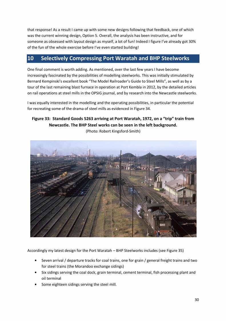
I was equally interested in the modelling and the operating possibilities, in particular the potential
for recreating some of the drama of steel mills as evidenced in Figure 34.
Figure 33: Standard Goods 5263 arriving at Port Waratah, 1972, on a “trip” train from
Newcastle. The BHP Steel works can be seen in the left background.
(Photo: Robert Kingsford-Smith)
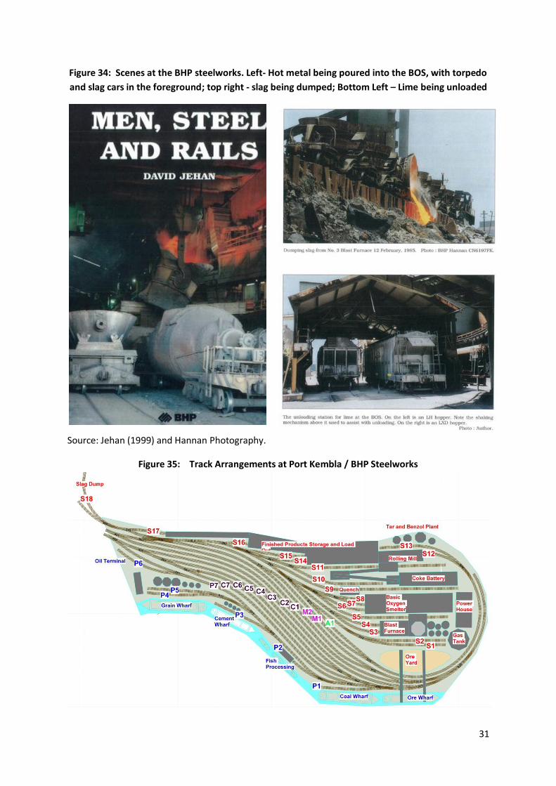
Accordingly my latest design for the Port Waratah – BHP Steelworks includes (see Figure 35)
Seven arrival / departure tracks for coal trains, one for grain / general freight trains and two
for steel trains (the Morandoo exchange sidings)
Six sidings serving the coal dock, grain terminal, cement terminal, fish processing plant and
oil terminal
Some eighteen sidings serving the steel mill.
31
Figure 34: Scenes at the BHP steelworks. Left- Hot metal being poured into the BOS, with torpedo
and slag cars in the foreground; top right - slag being dumped; Bottom Left – Lime being unloaded
Source: Jehan (1999) and Hannan Photography.
Figure 35: Track Arrangements at Port Kembla / BHP Steelworks
32
The Port Waratah yard tracks are allocated as follows:
Track A1 is the priority shunting track for internal steelworks movements
Tracks M1 and M2 are the Morandoo exchange sidings where wagons are exchanged
between the steelworks private lines and the NSW government railways
Tracks C1 to C7 are coal train yard tracks
Track P7 is the arrival / departure / shunting track for the Port Waratah sidings
This design supports a wide variety of switching assignments within the steelworks (see Table 3) and
with the Morandoo exchange sidings. There are thirteen separate switching assignments plus an
equivalent number of empty moves. This would keep an operator fairly busy, especially with priority
movements such as the transfer of hot metal and slag from the blast furnace.
Table 3: Steelworks Switching Moves (Loaded cars)
Type From To Wagon Type
Limestone to Blast Furnace Morandoo (M1, M2) High Line (S1) Limestone Hopper
Coke to Blast Furnace Morandoo (M1, M2) High line (S2) Coke Hopper
Cokeworks to Blast Furnace Coke Quencher (S9) High Line (S2) BHP Coke Hopper
Coal to Cokeworks Morandoo (M1, M2) Cokeworks (S11) Coal Hopper
Molten Iron to BOS Blast Furnace (S3, S4) BOS (S6) Torpedo Cars
Blast Furnace Slag to Slag Dump Blast Furnace (S5) Slag Dump (S18) Slag Dump Car
Scrap Steel to BOS Morandoo (M1, M2) BOS (S7) Gondola
Steel to Rolling Mill BOS (S8) Rolling Mill (S12) Ingot Cars
Tar Products for export Tar/Benzol Plant (S13) Morandoo (M1,2) Tank Cars
Flat Steel to export Finished products (S14) Morandoo (M1,2) Special Wagons
Steel Slab for export Finished products (S15) Morandoo (M1,2) Flat wagons
Specialty steel for export Finished products (S16) Morandoo (M1,2) Vans
Coil Steel to export Finished products (S17) Morandoo (M1,2) Open wagons, Coil Wagons
Port Waratah itself also has a range of sidings:
P1 is for the coal wharf for export coal
P2 serves the fish processing plant adjacent to the fishing fleet
P3 serves the cement wharf (inbound cement)
P4 and P5 serve the grain wharf (outbound)
P6 serves the oil terminal (inbound)
This supports significant switching options in addition to the extensive yard operations at
Broadmeadow, and the additional operations at Newcastle, Sulphide Junction, Fassifern and the
various on-line industries (for example there are four such industries between Newcastle / Port
Waratah and Broadmeadow), as well as the three visible coal mines, Cardiff workshops and the
Sulphide Works. Altogether the layout will have over 50 industry sidings.
33
10 Conclusion
Explaining the thinking behind the design of my second Newcastle – Fassifern layout has been a lot
of fun as well as instructive, in that it forced me to consider some of the practical aspects alongside
the aesthetic and operational ones. The real fun will begin in 2014 when the shed is ready for
occupancy! Until then I’ll probably keep tinkering with the designs, and it’s always possible I’ll come
up with an entirely new option!
Any feedback or suggestions from similarly afflicted layout designers are always welcome. I can be
contacted on [email protected].
Acknowledgements
I’d like to acknowledge thanks to all the people at LDSIG and OPSIG who have further encouraged me
in what is an obsession within an obsession! - in particular Byron Henderson, David Parks, Seth
Neuman and Chuck Catania whom I met on a visit to the 2011 NMRA convention, as well a number of
others in the US including John Pryke, Howard Zane, George Sellios, Dan Vandermause, Scott Dunlap
and Jeff Taylor who I have met on various trips and who have provided inspiration and ideas. I would
also like thank my many colleagues in Australia including Marcus Amman, Alistair Gilmour, Erik
Bennett, Laurie Moses, Allan Garbutt, Phil Collins, Jack Russell, Derek Cullen, John Bryan, Josh
Beveridge, George Bambery (who is building a 30 foot by 40 foot layout based on the Fassifern –
Broadmeadow area), David Latham, Ray Love, Ray Pilgrim and others who have helped me with
comments, taken part in operating sessions on my own or their layouts or provided helpful feedback
on this article. I would also like to especially thank Robert Kingsford-Smith and David Jehan who very
generously provided many of the prototype photos which appear in the article. Finally I would like to
thank my wife who has indulged my obsessions in this area over many years, including agreeing to
relocate to the southern highlands.
REFERENCES
Peter Attenborough (2002): “The Short North . Wyong – Fassifern”. Byways of Steam 20, Eveleigh
Press.
Peter Attenborough (2004): “The Short North. Fassifern-Newcastle”. Byways of Steam 22, Eveleigh
Press.
David Jehan (1999): “Men, Steel and Rails” the Operations of the BHP Newcastle System from the
Introduction of Diesel Traction to the Closure of Primary Steelmaking in 199”. ISBN 1 87663 409 X.
Published by the BHP Rod, Bar and Wire Division in association with the Light Railway research
Society of Australia – NWS Division.
Bernard Kempinski (2010): “The Model Railroader’s Guide to Steel Mills”. Kalmbach Books. ISBN 978-
0-89024-751-8.
Ray Love (2010): “The Steam Locomotive Depots in NSW. Depot No 20: Port Waratah”. Byways of
Steam No 27. Eveleigh Press. ABN 70 000 558 574.

34
Robert McKillop and David Sheedy (2008): “Our Region, Our Railway. The Hunter and the Great
Northern Railway 1857 – 2007”, Australian Railway Historical Society. NWS Division.
Ron Preston (2000): “The Railways of New South Wales – In Steam: Short North”. Orion Fine Arts.
ISBN 0 9577825 4 3.
John Pryke (2000): “Building city scenery for your model railroad”. Kalmbach Books. ISBN 0-98024-
343-3.
Pelle Soeberg (2012): “Rebuilding a Layout from A to Z. Building a better layout the second time
around”. Kalmbach Books. ISBN 978-0-89024-817-1


![Looking back and looking forward[1]](https://img.pdfslide.net/doc/110x75/5559ad0dd8b42aa4288b511b/looking-back-and-looking-forward1.jpg)