Embed Size (px)
Citation preview

Low-cost testbed development and itsapplications in cognitive radio prototyping
Tomaz Solc, Carolina Fortuna, Mihael Mohorcic
To be published in Cognitive Radio and Networking for Heterogeneous Wire-less Networks. Copyright (c) 2014 Springer International Publishing Switzer-land. Permission granted to use this manuscript for non-commercial and edu-cational purposes.
Abstract Having a huge potential to improve the way radio spectrum is being used,the techniques that are used for the research in cognitive radio are maturing andtherefore move from being evaluated in a simulation environment to more realisticenvironments such as dedicated testbeds. In this chapter we describe our experienceswith the design, deployment and experimental use of the LOG-a-TEC embedded,outdoor cognitive radio testbed, based on the VESNA sensor node platform. We de-scribe the choice of experimental low-cost reconfigurable radio frontends for LOG-a-TEC and discuss the potential capabilities of custom designs. The core part ofthis chapter gives practical experiences with designing the embedded testbed infras-tructure, covering topology design and performance evaluation of the managementnetwork as well as our considerations in the choice of network protocols employedin the LOG-a-TEC testbed. Finally, we provide two use cases where the LOG-a-TEC testbed has been used for performing experiments with cognitive radio, onerelevant to the investigation of coexistence of primary and secondary users in TVwhite spaces and the other addressing power allocation and interference control inthe case of shared spectrum.
Tomaz Solc,Jozef Stefan Institute, Jamova 39, 1000 Ljubljana, Slovenia, e-mail: [email protected]
Carolina Fortuna,Jozef Stefan Institute, Jamova 39, 1000 Ljubljana, Slovenia, e-mail: [email protected]
Mihael Mohorcic,Jozef Stefan Institute, Jamova 39, 1000 Ljubljana, Slovenia, e-mail: [email protected]
1

2 Tomaz Solc, Carolina Fortuna, Mihael Mohorcic
1 Introduction
As a research area in wireless communications that is fundamentally important formore efficient use of radio spectrum, cognitive radio already surpassed the earlyphase of theoretical only investigations in controlled environments and computersimulations, and has already entered the phase of experimental research and pilottrials in increasingly realistic operating environments. This has been recognised bya number of institutions and projects worldwide, resulting in numerous testbeds, onone hand trying to be sufficiently representative for actual targeting scenarios, andon the other hand striving to be easy for use and to be able to accommodate as di-verse algorithms and approaches as possible. As a result, they are inclined towardsthe use of high-performance general purpose processors and software defined radio(SDR) platforms. Conventional testbeds that are built around this architecture offer afast way for researchers to implement and test various protocols. However cognitiveradio technologies are also interesting for low-powered and low-bandwidth appli-cations, like wireless sensor nodes and body area networks. Such applications oftendo not have the possibility of including a software defined radio platform in the finalproduct due to power and cost constraints. While most of the basic research can stillbe done on conventional testbeds, aspects like power, storage and processing limita-tions on such systems can only be reliably tested on embedded hardware that moreclosely resembles realistic platforms such applications would run on. Embeddedtestbeds can also be more easily deployed in configurations where a conventionalapproach would be difficult. One example of that are outdoor environments, whereoperation of delicate laboratory equipment can be problematic. Another exampleare locations that lack existing infrastructure such as Ethernet wiring or constantpower supply. The relatively low cost of embedded devices can also be an importantbenefit in testbeds consisting of a large number of nodes.
A node in a conventional testbed is typically built around a computer running aGNU/Linux-based operating system with a software defined radio front-end and aTCP/IP based management network. A typical setup consists of nodes with a giga-byte of RAM, x86 CPU in the gigahertz clock range and connection to a gigabitEthernet network. On the other hand, testbeds built up by embedded devices suchas the Tmote Sky [1] or VESNA [2] wireless sensor nodes, are powered by micro-controllers with CPU cores like AVR or ARM with clock frequencies in the 10 to100 MHz range and RAM sizes from 1 to 100 kilobytes. Typically communicationbetween the nodes involves low-power narrow-band radios with bulk transfer ratesin the range from 100 bytes per second to 100 kilobytes per second. Nodes in such asetup either run specialized, small-footprint operating systems like Contiki [3] andTinyOS [4] or even just bare bone firmware without a proper operating system. Net-work protocols encountered in such testbeds are for example IEEE 802.15.4, ZigBeeand Bluetooth. Such systems offer very little built-in management functionality thatis usually expected from conventional, networked multi-user computers. Thereforethe design and use of embedded testbeds pose several additional challenges overthose found in conventional testbeds.

Low-cost testbed development and its applications in cognitive radio prototyping 3
In this chapter we describe our experiences with the design, deployment andexperimental use of the LOG-a-TEC embedded, outdoor cognitive radio testbed,based on the VESNA [2] sensor node platform, which is integrated with the CREWfederation [5] of cognitive radio testbeds. Where possible, we also mention otherapproaches to design challenges that were taken in other similar testbeds. We de-scribe the choice of experimental radio frontends for LOG-a-TEC and discuss thepossibility of custom designs. We also give practical instructions for designing thetestbed infrastructure, like the management network and our considerations in thechoice of network protocols employed in the LOG-a-TEC testbed. Finally, we pro-vide two use cases where the LOG-a-TEC testbed has been used for performingexperiments with cognitive radio.
The chapter is organized as follows. Section 2 discusses radio front-end for em-bedded testbeds and gives details for the ones used in LOG-a-TEC. Section 3 dis-cusses the infrastructure of the testbed including deployment considerations, net-work design constraints, planning of the management network and the mechanismsthat enable access, control and reconfiguration. Section 4 presents a signal gen-eration use case in which the SNE-ISMTV-TI868 transceiver is used to emulatewireless microphone profiles. Section 5 presents an interference mitigation use caseusing a simple power allocation experiment on LOG-a-TEC. Finally, Section 6 sum-marizes the chapter.
2 Radio front-ends for embedded testbeds
Software defined radio has become an indispensable tool in communications re-search. It has allowed for very short development cycles for various protocols fromthe physical layer up. It has also significantly lowered the entry barrier to proto-typing. With a software defined radio architecture a researcher only needs a per-sonal computer with a relatively inexpensive radio frontend, while previously a fullyequipped electronics laboratory was needed. The developer also does not need toknow details of radio frequency electronic circuit design. In fact, physical radiofront-ends can often be interchanged in a modern SDR design without much workthanks to layers of software that provide high-level abstractions over the hardwaredetails. With the advent of frameworks like GNU Radio [6] and IRIS [7] one candevelop complete RF systems in high level languages such as Python and XML orusing user-friendly graphical tools like the GNU Radio Companion.
However this flexibility of SDR architectures and the convenience it offers tothe developer comes with a cost in terms of processing performance, RAM andpower requirements. While the throughput of embedded general-purpose proces-sors is continuously improving, low-powered embedded devices are still a long wayfrom supporting full-fledged SDR frameworks. One of the reasons is that batterycapacity has not been scaling together with processor performance. It is likely there-fore that battery powered and low cost devices will not be able to support the SDRdevelopment model for the foreseeable future.

4 Tomaz Solc, Carolina Fortuna, Mihael Mohorcic
Fig. 1 Modular design of the VESNA wireless sensor network platform consisting of three typesof modules, core (SNC), radio (SNR) and expansion (SNE).
On the other hand, the basic requirements for a cognitive radio can also be sat-isfied with architectures that are not fully software defined. There are commerciallyavailable low-power reconfigurable integrated transceivers that target developers ofproprietary radio protocols for embedded devices. These are capable of covering alarge part of radio requirements for simple cognitive terminal and dynamic spectrumaccess implementations: they are reasonably accurate at sensing the spectrum usageusing energy detection, they have frequency agile local oscillators that permit fastfrequency hopping and interference avoidance and allow software to reconfigureparameters of their transmissions like modulation scheme and channel bandwidth.
This chapter is focusing on cognitive radio testbeds based on low-power embed-ded devices and as a concrete representative of such devices we mostly refer to theVESNA sensor node platform [2].
2.1 VESNA with the SNE-ISMTV expansion
VESNA [2] is a modular wireless sensor node platform generally consisting of threeprinted circuit boards: Sensor Node Core (SNC), Sensor Node Radio (SNR) andSensor Node Expansion (SNE) as depicted in Figure 1.
The SNC board contains a 32-bit ARM Cortex-M3 microcontroller running at upto 72 MHz CPU clock. It has 96 kB of RAM and 1 MB of flash program memory.Additional non-volatile memory is provided by a micro SD card. The microcon-troller integrates 3 A/D converters that can be used to sample analog signals with upto 1 Msample/s. Two of these converters can also be combined to sample a singlesignal with 2 Msamples/s. Power is provided by a versatile subsystem that is capa-ble of powering the sensor node from diverse sources, including photovoltaic cellsand batteries.
VESNA supports a number of different wireless interfaces on the SNR board.Some SNR boards contain bare integrated transceivers while other carry radio mod-ules that include both a transceiver and an additional microcontroller for networkstack offloading. In the most common wireless sensor network deployment use case,VESNA nodes use a proprietary Atmel ZigBit low-powered radio module to connectto a wireless mesh network. In such use case, the SNE board is used for application
Low-cost testbed development and its applications in cognitive radio prototyping 5
specific hardware, usually to connect sensors to the node that cannot be accommo-dated by the interfaces on the core board itself.
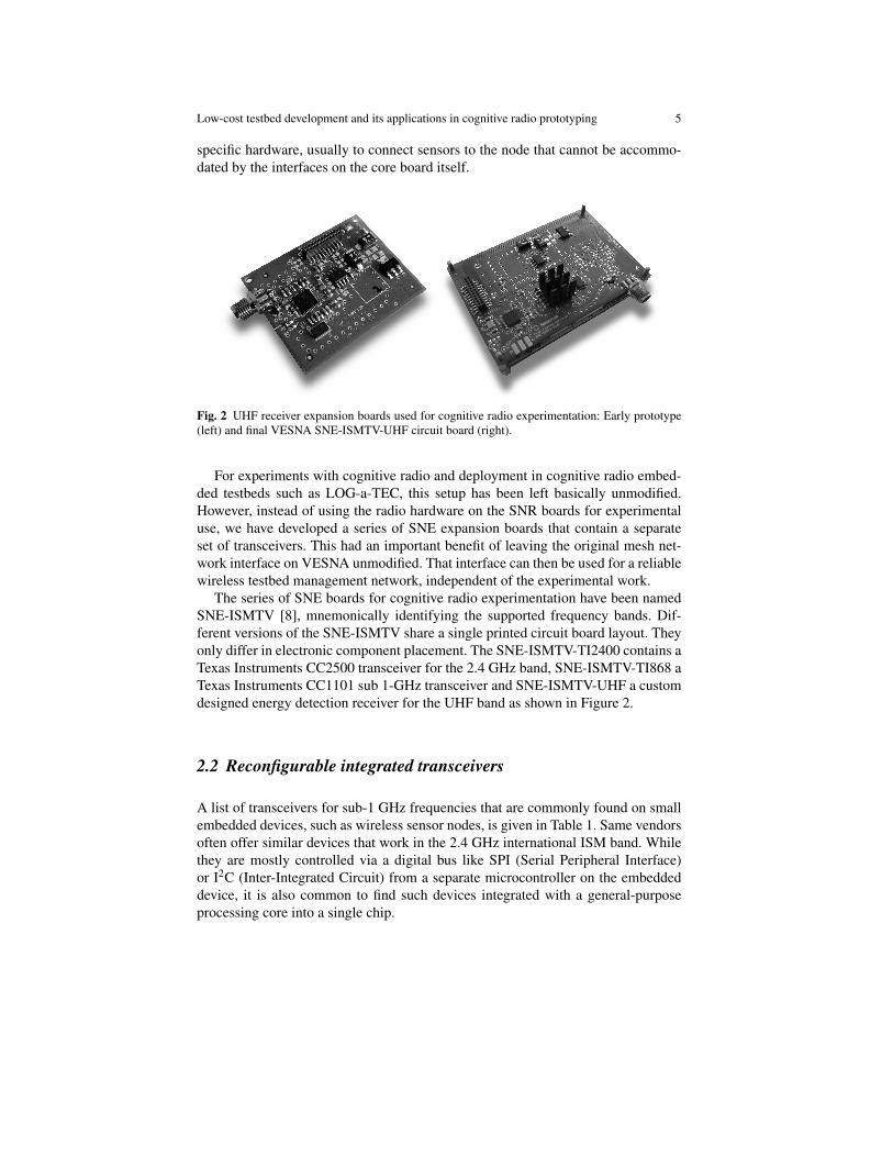
Fig. 2 UHF receiver expansion boards used for cognitive radio experimentation: Early prototype(left) and final VESNA SNE-ISMTV-UHF circuit board (right).
For experiments with cognitive radio and deployment in cognitive radio embed-ded testbeds such as LOG-a-TEC, this setup has been left basically unmodified.However, instead of using the radio hardware on the SNR boards for experimentaluse, we have developed a series of SNE expansion boards that contain a separateset of transceivers. This had an important benefit of leaving the original mesh net-work interface on VESNA unmodified. That interface can then be used for a reliablewireless testbed management network, independent of the experimental work.
The series of SNE boards for cognitive radio experimentation have been namedSNE-ISMTV [8], mnemonically identifying the supported frequency bands. Dif-ferent versions of the SNE-ISMTV share a single printed circuit board layout. Theyonly differ in electronic component placement. The SNE-ISMTV-TI2400 contains aTexas Instruments CC2500 transceiver for the 2.4 GHz band, SNE-ISMTV-TI868 aTexas Instruments CC1101 sub 1-GHz transceiver and SNE-ISMTV-UHF a customdesigned energy detection receiver for the UHF band as shown in Figure 2.
2.2 Reconfigurable integrated transceivers
A list of transceivers for sub-1 GHz frequencies that are commonly found on smallembedded devices, such as wireless sensor nodes, is given in Table 1. Same vendorsoften offer similar devices that work in the 2.4 GHz international ISM band. Whilethey are mostly controlled via a digital bus like SPI (Serial Peripheral Interface)or I2C (Inter-Integrated Circuit) from a separate microcontroller on the embeddeddevice, it is also common to find such devices integrated with a general-purposeprocessing core into a single chip.

6 Tomaz Solc, Carolina Fortuna, Mihael Mohorcic
Transceiver Modems Bitrate [kb/s] fc [MHz] BW [kHz] Hop time [µs]TI CC1101 FSK, GFSK, OOK 0.6 - 500 779 - 928 58 - 812 75
ASK, MSKSilicon Labs Si4313 FSK, GFSK, OOK 0.2 - 128 240 - 960 2.6 - 620 200Nordic Semi nRF905 GFSK 50 430 - 928 100 650
Table 1 List of common reconfigurable sub-1 GHz transceivers.
A typical block diagram of these reconfigurable transceivers is shown in Figure3. They all have a single chip design that requires very little in terms of externalcomponents. Rarely, they are coupled to an external power amplifier for range ex-tension and/or an external low noise amplifier for improved noise figure.
Fig. 3 Block diagram of a typical reconfigurable transceiver.
A PLL frequency synthesizer is used both as a local oscillator in the receptionmode and as a frequency agile sine-wave generator in transmission mode. A pro-grammable digital or an analog filter bank provides channel selectivity that is re-configurable from software. Several modulation and demodulation blocks can alsobe software selected. Additionally, packet handling logic can be enabled, which canbe used to off-load start symbol detection, whitening, CRC calculation and similartasks from the main CPU. Since the frequency synthesizer is shared between receiveand transmit chains they typically allow only half-duplex operation.
Disabling packet handling hardware allows for continuous reception or transmis-sion by streaming digital data to or from the transceiver. This allows for interpreta-tion of such a stream as a sampled analog signal which opens interesting possibil-ities, like emulation of analog transmissions. It should be noted though that thesetransceivers do not typically allow access to the raw signal samples from the ADC.The only data stream available to the CPU is one provided by integrated demodula-tor blocks. This prevents development of spectrum sensing methods beyond energydetection and signal processing using such hardware.

Low-cost testbed development and its applications in cognitive radio prototyping 7
2.2.1 Energy detection
Most transceivers include an integrated logarithmic detector behind the channel fil-ter that can be used as a received signal strength indicator (RSSI). While this ca-pability is meant to be used for the implementation of clear-channel assessment,listen-before-talk and CS-MAC protocols, it can also be used as a simple energydetector for signals within the tuned RF channel. This capability is well known inthe research community since it is often used for spectrum sensing experiments oras a low-cost spectrum analyzer. In this case, the transceiver is set to receive modeand swept through a list of channels as presented in the flowchart in Figure 4. Oneach channel, a RSSI measurement is taken. Such measurements are limited in theresolution bandwidth by the available settings for the channel filter and in the sweeptime by the settling of various automatic gain control (AGC) stages in the receiver.
Fig. 4 Typical flowchart for aprocedure performing energydetection spectrum sensing ona part of spectrum betweentwo RF channels, start chanand stop chan, with a recon-figurable transceiver.
8 Tomaz Solc, Carolina Fortuna, Mihael Mohorcic
Typical measurements take between 5 to 50 ms per channel and have a resolution of0.5 dB.
When using the RSSI indicator in such a way, care must be taken with respect tothe interpretation of the obtained results. Chips often have offsets that require cali-bration, if absolute values of the incident power are required. Detectors commonlyalso have a strong temperature dependency that might lead to wrong conclusions (asnoted for example in [9]).
It is also important to note that since the logarithmic detector measures totalpower after the channel filter, its readings are only approximately equal to the signalpower when signal power is significantly above the receiver noise floor. In caseswhere the signal to noise ratio is close or below 1, only reading the RSSI is not anaccurate indicator of the signal level and more advanced methods are required, suchas using link quality indicator (LQI) as indicator of signal to noise ratio [10].
2.2.2 Programming interface
The connection between a low-powered transceiver and the central CPU on the em-bedded device usually takes the form of an embedded serial control bus, like SPIor I2C. The transceiver exposes a small address space (typically 8-bit) to the con-trolling CPU over this bus. Most transceivers also provide additional interrupt lines.These can be used to simplify software on the CPU and also provide a more accuratetiming of packet reception or transmission than what can be achieved using a serialbus.
The radio configuration typically requires setting around 50 hardware registersaccessible from the control bus. For example, the channel filter bandwidth may beset by writing appropriate values to bits 4 through 7 into an 8-bit register at address0x10 as presented in Figure 5 line 9. Usually the exact register settings are derivedfrom the calibration values that are only known to the transceiver manufacturer. Be-cause of that, the specified performance of the radio can often only be achievedby using values calculated by specialized software for each transceiver configura-tion such as the one depicted in Figure 6. In such case, a cognitive terminal muststore a predefined set of radio configurations that have been precalculated using themanufacturer’s software.
Data reception and transmission is similarly performed through FIFO buffersaccessible over the control bus, although sometimes a completely separate digitalbus is used for streaming data as is the case for example in CC1101 in continuoustransmission/reception mode.
There is currently no unified interface that would allow for fast prototyping of so-lutions using such hardware. Compared to high level scripting provided by the GNURadio platform, here typically the developer has to have intimate knowledge of theradio hardware. In the future, standardised transceiver APIs might improve this sit-uation. Similarly, there has been recently some development in open source SDRframeworks that allow for delegation of certain signal processing tasks to hardwareblocks like the ones found on the reconfigurable transceivers discussed here (for ex-

Low-cost testbed development and its applications in cognitive radio prototyping 9
1. uint8_t initSeq[] = 2. CC1100_IOCFG2, 0x0B, // GDO2Output Pin Configuration3. CC1100_IOCFG0, 0x0C, // GDO0Output Pin Configuration4. CC1100_PKTCTRL0, 0x22, // Packet Automation Control5. CC1100_FSCTRL1, 0x08, // Frequency Synthesizer Control6. CC1100_FREQ2, 0x58, // Frequency Control Word7. CC1100_FREQ1, 0xE3, // Frequency Control Word8. CC1100_FREQ0, 0x8E, // Frequency Control Word9. CC1100_MDMCFG4, 0x86, // Modem Configuration10. CC1100_MDMCFG3, 0x75, // Modem Configuration11. CC1100_MDMCFG2, 0x00, // Modem Configuration12. CC1100_MDMCFG0, 0xE5, // Modem Configuration13. CC1100_DEVIATN, 0x67, // Modem Deviation Setting14. CC1100_MCSM0, 0x18, // Main Radio Control State15. // Machine Configuration16. CC1100_FOCCFG, 0x16, // Frequency Offset Compensation17. CC1100_FSCAL1, 0x00, // Frequency Synthesizer Calibration18. CC1100_FSCAL0, 0x11, // Frequency Synthesizer Calibration19. CC1100_PATABLE, 0xFE, // TX power 0 dBm20. 0xFF, 0xFF21. ;22.23. static void radioSetup(void)24. 25. vsnCC_disableRadioInterrupt();26. vsnCC_init();27. vsnCC_radioReset();28.29. vsnCC_strobe(CC1100_SIDLE);30. radioWaitState(CC_MARCSTATE_IDLE);31.32. int n;33. for(n = 0; initSeq[n] != 0xff; n += 2) 34. uint8_t reg = initSeq[n];35. uint8_t value = initSeq[n+1];36. vsnCC_write(reg, value);37. 38.
Fig. 5 Example code required to setup a CC-series transceiver for continuous transmission onVESNA platform.
ample specialized engines in IRIS). However, these frameworks still remain muchtoo large for a typical microcontroller system today.
2.2.3 SNE-ISMTV-TI868 and SNE-ISMTV-TI2400
As an example of using using low-power embedded devices for energy detec-tion based spectrum sensing we refer in the following to two versions of pur-posely developed SNE-ISMTV expansion board for VESNA using Texas Instru-ments CCxxxx transceivers with the main specifications summarised in Table 2 forSNE-ISMTV-TI868 and in Table 3 for SNE-ISMTV-TI2400. SNE-ISMTV-TI868uses the CC1101 chip and operates in the European 868 MHz short range de-vices (SRD) unlicensed band and upper channels of the UHF broadcast band. SNE-

10 Tomaz Solc, Carolina Fortuna, Mihael Mohorcic
Fig. 6 Screenshot of Texas Instruments SmartRF studio software.
ISMTV-TI2400, on the other hand, uses the CC2500 chip and operates in the 2.4GHz unlicensed international industrial, scientific, medical (ISM) band. Except forthe difference in the radio frequency, which requires different antenna matching cir-cuit, the two boards are mostly identical in hardware design. Similarly, the softwareinterface of CC1101 and CC2500 is largely identical, which greatly simplified driversoftware.
Parameter ValueCentral frequency range 780 to 871 MHzCentral frequency resolution 50 kHzChannel filter bandwidth 60, 100, 200, 400 or 800 kHzPower detector range -123 to 4 dBmPower detector resolution 0.5 dBmAverage noise level -150 dBm(1 Hz BW, 868 MHz)Channel sampling time 5 msTransmission power range -30 to 12 dBmTransmission power resolution 2 dBm
Table 2 SNE-ISMTV-TI868 specifications.
The analogue receive path on CCxxxx series transceivers consists of a low-noiseamplifier, quadrature down-converter and a channel filter. Additional filtering, gaincontrol and demodulation are performed in the digital domain, after the signal hasbeen digitized by an analogue-to-digital converter (ADC) at an intermediate fre-quency. A fractional-N PLL frequency synthesizer is used as a local oscillator.For transmission, the same frequency synthesizer is used to produce a modulatedquadrature signal which is amplified by a power amplifier stage. 50 Ω antennamatching is performed by an external LC balun network.

Low-cost testbed development and its applications in cognitive radio prototyping 11
Parameter ValueCentral frequency range 2400 to 2480 MHzCentral frequency resolution 50 kHzChannel filter bandwidth 60, 100, 200, 400 or 800 kHzPower detector range -123 to 4 dBmPower detector resolution 0.5 dBmAverage noise level -159 dBm(1 Hz BW, 2400 MHz)Channel sampling time 5 msTransmission power range -55 to 1 dBmTransmission power resolution 2 dBm
Table 3 SNE-ISMTV-TI2400 specifications.
The transceiver is connected to the sensor node core CPU with an SPI bus, whichexposes radio configuration registers and FIFO buffers. This low-level interface tothe transceiver has a form of a finite state machine. Digital radio control logic al-lows reconfiguration of the frequency synthesizer settings (base frequency, channelspacing) and baseband channel filter bandwidth. A logarithmic-response detectorcan be used to measure the RSSI. Baseband modulator and demodulator blocks arecapable of 2-FSK, 4-FSK, GFSK, MSK and ASK/OOK modulations. Continuoustransmission and reception using these modulations is possible with data streamedvia a dedicated digital bus on the transceiver’s auxiliary pins. Also available is apseudo-random sequence generator which can be used in continuous transmissionmode.
For packet-based transmissions, integrated packet handling hardware implementsa proprietary packet encapsulation scheme. This makes it mostly incompatible withstandard MAC layers like the one defined by IEEE 802.15.4. The hardware is ca-pable of preamble and synchronization word detection, data integrity check usingCRC, address filtering and data whitening.
In cognitive radio experiments so far, SNE-ISMTV-TI868 and SNE-ISMTV-TI2400 have been used as narrow-band energy detection spectrum sensing receiversusing the RSSI functionality in the 868 MHz and 2.4 GHz bands to build radio en-vironment maps or to supply channel occupancy information to cognitive terminals.
VESNA nodes with SNE-ISMTV expansion have also been used as controlledinterferers and targets for spectrum sensing using other devices. In this case, thecontinuous transmission mode of the transceiver has been used. The data sent waseither a pseudo-random sequence generated by the transceiver or a stream generatedon the sensor node’s CPU. With the latter option we have been able to approximateanalogue transmissions generated by wireless microphones.
To help with the problem of complicated low-level interface exposed by this typeof hardware an abstraction layer for software running on the sensor node has beendeveloped. This simplifies programming for two common tasks: energy detectionand signal generation. For each version of the SNE-ISMTV board, several hardwareprofiles have been defined that specify PLL settings (channel base and spacing) andmodem configuration.

12 Tomaz Solc, Carolina Fortuna, Mihael Mohorcic
2.3 Getting closer to SDR with custom hardware
Microcontrollers that integrate multiple analog-to-digital and digital-to-analog con-verters in the Msample/s range make for an inviting target for an embedded versionof a software-defined architecture. With a suitable front-end and anti-aliasing filtersthese can be used to generate or sample signals directly.
However, the processor throughput of such devices is typically far behind the ca-pability of processing a continuous stream from its ADC in real-time. For example,a STM32F1 family microcontroller running at 64 MHz, which is near the top of therange for an ARM Cortex M3 core without DSP extensions, will only process sig-nals on the order of 100 ksample/s even when doing the simplest signal processingtasks.
Processors with large RAM sizes have the possibility of capturing an interval ofsignal samples and then doing off-line processing. This type of processing, however,has limited usability in cognitive radio applications beyond spectrum sensing.
2.3.1 TV Band Spectrum sensing with SNE-ISMTV-UHF
The VESNA expansion board for spectrum sensing in the UHF and VHF bands hasbeen developed specifically for research into heterogeneous spectrum sharing andcognitive radio applications in the TV-band whitespaces. It is based on a cheap andcompact multi-standard TV silicon tuner design which allows it to be deployed inlarge sensor networks for distributed sensing applications.
SNE-ISMTV-UHF contains a VHF and UHF TV band receiver based on the NXPTDA18219HN silicon tuner and was designed for spectrum sensing experimentationin TV white spaces (TVWS). Figure 2 presented an early version of the receiver andthe final printed circuit board used in LOG-a-TEC. The TDA18219HN silicon tunerintegrates a low-noise amplifier, RF tracking filters, single down-conversion lowintermediate-frequency image-rejection mixer, frequency synthesizer and selectablechannel filters. It also includes multiple stages of analogue automatic gain control(AGC).
Fig. 7 Block diagram for signal reception using VESNA with SNE-ISMTV-UHF.
Individual receiver stages can be reconfigured through a state machine with anI2C bus interface. Digital control logic also controls built-in test tone generator andRF filter calibration.

Low-cost testbed development and its applications in cognitive radio prototyping 13
For energy detection, SNE-ISMTV-UHF offers two detectors with a logarithmicresponse. A high-range detector is built into TDA18219HN and has a range from-80 to 0 dBm with 1 dBm resolution. The measurement is controlled via a statemachine internal to TDA18219HN which is armed and triggered through the digitalI2C bus. The measurement process includes signal averaging.
For measuring signals below -80 dBm, a demodulating logarithmic amplifierAnalog Devices AD8307 is connected between the TDA18219HN intermediate fre-quency output and the 1 Msample/s analogue-to-digital converter on the VESNASNC (Sensor Node Core) as depicted in Figure 7. This puts sampling of the signalpower level in control of the firmware, allowing various averaging and samplingmethods. Additionally, gain in the intermediate frequency stage can be adjusted viaa variable-gain amplifier controlled by a digital-to-analogue converter (DAC) in theSNC.
To lower the power consumption, both the logarithmic amplifier (via ENB pin)and the tuner (via I2C sleep-mode control registers) can be powered down.
Two hardware profiles are provided that differ in energy detector resolution band-width. A wide-band setting sets the channel filter to 8 MHz, allowing energy detec-tion at the bandwidth of a complete DVB-T channel. A narrow-band setting sets thechannel filter to 1.7 MHz and is suitable for detection of wireless microphones andsecondary users in the TV white spaces.
While TDA18219HN and the SNE-ISMTV designs allow operation down to 42MHz, there are currently no hardware profiles available for VHF frequency band.
Since it is based on a DVB-T tuner, this extension board is not capable of sig-nal transmission in contrast to the extension boards SNE-ISMTV-TI868 and SNE-ISMTV-TI2400, as described in the previous section.
2.4 Summary
In summary, reconfigurable low-power transceivers are capable of performing manyradio frontend duties in a cognitive radio setup. However the development of solu-tions is far from being as accessible as with software defined radio architectures.Such devices deployed in a testbed can be used for instance in a supporting rolefor other, more full featured cognitive terminals. They can perform energy detec-tion spectrum sensing in a distributed fashion. Reconfigurable transceivers are alsoflexible enough to take an active role in certain dynamic spectrum access schemes.
With SNE-ISMTV-UHF, we are looking at ways of getting closer to softwaredefined radio using a custom designed low-cost receiver for the VHF and UHFbands based on a commercial integrated silicon tuner. In contrast to reconfigurabletransceivers, however, devices with tuners can only be used in cognitive radio appli-cations for spectrum sensing, with capabilities depending on the accessibility of thesignal at different stages within the receiver.

14 Tomaz Solc, Carolina Fortuna, Mihael Mohorcic
3 Testbed infrastructure
In order to perform real-life experiments with communication protocols, represen-tative testbeds are needed. Such testbeds can typically consist of a few devices up tohundreds of devices. On the devices experimental implementations of protocols arebeing run in various scenarios and the results are recorded and later analyzed. Thisway the performance of the protocols can be evaluated and possibly improved. Tofacilitate the research activity in dynamic spectrum allocation we created a testbedcalled LOG-a-TEC primarily for experimentation with spectrum sensing, cogni-tive radio networking and testing of arbitrary protocols on low-cost low-complexityhardware.
In order to use the embedded devices such as VESNA based sensor nodes withexpansion boards described in Section 2 in a cognitive radio testbed, the overalltestbed infrastructure needs to be carefully planned and set up accordingly, includ-ing (i) the management network, wireless or wired, for configuration of nodes andcollection of sensing data, (ii) locations for mounting nodes and antennas, (iii) pro-vision of power for nodes in case of external powering, (iv) adequate data storageand processing capabilities, and (v) a suitable system administration user interface.
Because a cognitive radio testbed is used to experiment with the communicationbetween the nodes, the radio interface used by experiments is unreliable and nodesneed to be equipped with additional radio interface for the management network toprovide remote access to the nodes.
A testbed infrastructure may also provide power to the nodes in the testbed. Incomparison to conventional testbeds, where external power is a must, the physicalrequirements for the infrastructure are much more relaxed in embedded testbeds.Nodes can be battery powered for the duration of the experiment. Also the manage-ment network need not to consist of gigabit Ethernet cabling but can be wireless.
While an embedded testbed is focused on cognitive radio applications that mightone day be used in mobile, battery powered devices, most such testbeds are notthemselves battery powered, especially those that are permanently deployed. Atestbed might use low-powered processors and radio to conduct exclusively tests ofwireless protocols and does not focus on the power consumption aspect of its opera-tion. Thus it is not uncommon that in an embedded testbed each low-powered nodeis accompanied by a conventional, networked computer that provides managementfunctionality. This significantly simplifies management of the testbed. Embeddedoperating systems running on nodes often do not support run-time reprogrammingor include system administration functionality that is common on multi-user sys-tems like GNU/Linux.
3.1 LOG-a-TEC testbed deployment
The LOG-a-TEC testbed was deployed in the town of Logatec, Slovenia [11][12].It consists of two clusters, each cluster being composed of 25 devices. One cluster

Low-cost testbed development and its applications in cognitive radio prototyping 15
is located in the industrial zone and the other in the town center. The location ofthe two clusters inside Logatec is presented in Figure 8. The pentagonal markersrepresent the locations the nodes. The cluster of markers situated in the upper sideof Figure 8 corresponds to the industrial zone, while the cluster of markers on thelower side of the same figure corresponds to the town centre. The majority of devicesin both clusters are installed on public light poles and connected to external powersupply.
Fig. 8 Locations of the device clusters inside Logatec.
The deployed devices are based on the VESNA hardware platform [2] describedin Section 2. Each VESNA is equipped with multiple radio modules:
• Atmel’s ZigBit radio module ATZB-900-B0 operating in the license-free 868MHz European SRD band is used for the management network.
• One of the three radio modules for spectrum sensing and cognitive radio ex-perimentation that can be hosted on the SNE-ISMTV extension board describedin Section 2.1, i.e. CC1101 and CC2500 from Texas Instruments or the customdesigned spectrum sensing receiver operating in the UHF TV band.
• Atmel’s IEEE 802.15.4 compliant radio AT86RF212 operating in the license-free868 MHz European SRD band for communication experiments.
Each VESNA is thus equipped with one of the following three combinations of theradios:

16 Tomaz Solc, Carolina Fortuna, Mihael Mohorcic
• ATZB-900-B0 + CC1101 for 868 MHz sensing + AT86RF212• ATZB-900-B0 + CC2500 for 2.4 GHz sensing + AT86RF212• ATZB-900-B0 + TV receiver for UHF sensing + AT86RF212
The logical block diagram of one cluster of the testbed is depicted in Figure 9. Thecluster has two parts that are situated at different physical locations. The first part,where the experiments will be performed, is located in Logatec and is illustrated onthe left side of Figure 9 and consists of a set of VESNA nodes and the cluster coor-dinator. This part is connected to the Internet through its Gateway that correspondsto the VESNA coordinator and internally uses a ZigBee network for communica-tion. The second part of the testbed, presented on the right hand side of Figure 9,is the infrastructure serving the experimental part. This part consists of a PC run-ning an HTTP server that is connected to the Internet and communicating with theGateway. This server provides an HTTP API which supports programmatic accessto VESNA’s REST interface and also hosts the LOG-a-TEC web portal depicted inFigure 10. This portal renders a map with the location of VESNAs and their status,allows manually issuing GET and POST requests and supports running simulationswith the GRASS-RaPlaT [13] tool.
Fig. 9 The logical block diagram of one cluster in LOG-a-TEC.
The currently supported VESNA software stack is depicted in Figure 11 and canuse libopencm3 or STM32FWLib as an abstraction layer towards hardware regis-ters and MCU peripherals. While the first library is released under an open sourcelicense (LGPL), the second is proprietary. VESNA drivers then provide a high levelabstraction to support storage, various sensors and functionalities of the platformwhich may run the event driven Contiki operating system if needed. In many ap-plications, including LOG-a-TEC, we use application specific software without anoperating system. On VESNA, an application can run (1) on top of the Contiki OS,(2) run without an OS using the drivers or (3) run without an OS using libopencm3.The decision on how to build an application depends on licensing constraints and onthe complexity of the application. For the case of LOG-a-TEC, the second optionusing STM32FWLib, VESNA drivers and a custom application was selected. Theapplication provides (1) a REST interface that supports remote experiments, (2) na-tive code for local experiments and (3) testbed management functionalities such asover-the-air reprogramming and monitoring.
The control of the SNE-ISMTV extension for the purpose of experimentationcan be achieved in several ways as illustrated in Figure 11. Currently there are fourways of controlling an experiment that differ in terms of complexity, response timeand location. The higher the complexity required to control the hardware to perform

Low-cost testbed development and its applications in cognitive radio prototyping 17
Fig. 10 The LOG-a-TEC web portal.
Fig. 11 VESNA software stack (left) and layers of abstraction over SNE-ISMTV expansion boards(right).
the experiment, the lower the response time. Additionally, there are two options thatallow remote control of the experiment and two options that allow local only controlrequiring physical connection to the hardware.
A low-complexity approach that supports remote experiment control using a de-vice and testbed independent language using the XML syntax is to define an exper-iment using the CREW common data format (CDF) and then request the LOG-a-TEC infrastructure to run the defined experiment. The resulting measurement willbe provided in the form of CSV or Matlab files containing time, frequency andpower values resulting from the sensing experiment. A slightly higher complex-

18 Tomaz Solc, Carolina Fortuna, Mihael Mohorcic
ity approach that also supports remote experiment control is to use the availableREST interface. This assumes the experimenter downloads the available Python orJavascript tools 1 and writes the logic of the experiment using these tools. Usingthese tools, the experimenter is able to specify actions such as (i) sense band B attime T using device D and method M, and (ii) transmit at frequency F and power P.This second approach is the most frequently used.
A higher complexity approach to controlling the experiment is via direct access tothe C API from native code. This option removes network latency caused by networkround trips, on-board processing and interference from the wireless managementnetwork operating on 868 MHz. Finally, the most complex and time consuming wayof controlling the experiment is to directly program the hardware (i.e. the CC1101,CC2500 and TDA18219 chips) and exploit the full capabilities of the hardware. Thisapproach is time consuming as it requires testing but results in lower response timein terms of spectrum sensing and transmission.
3.2 Network design constraints
The design of ZigBee based wireless management network, which provides remoteoperation of the deployed testbed, needs to take into consideration the constraints ofthe devices and possible deployment locations [14]. One of the constraints of the de-sign of the network is the availability of frequency bands where the ZigBee networkcan operate. There are two choices for this network, the 2.4 GHz ISM band and the868 MHz SRD band. The 868 MHz SRD band offers better propagation character-istics and it does not interfere with the crowded 2.4 GHz ISM band, where majorityof spectrum sharing experiments are expected to be performed as opposed to TVWSrelated experiments in UHF band. Thus, the 868 MHz SRD band was chosen as theoperating band for the management network in the LOG-a-TEC testbed.
The locations for devices are constrained by the following factors:
• Availability of Internet access: the Gateway of each cluster has to be connectedto the Internet; for maximizing the performance, wired connection is preferred.
• Location of light poles (or alternative infrastructure): devices are mounted onlight poles belonging to the public lightning system. Possible exceptions are theGateway devices.
• Power connections to the light poles: the devices in LOG-a-TEC have alwaysavailable power source. Light poles are powered in groups, so economically themost suitable solution is to equip all light poles of the selected light pole groups.
• Connectivity: because all the devices will be accessed through the Gateway, formaximum performance it is important to have minimum number of hops fromany device to the Gateway.
1 The tools are available for download at https://github.com/sensorlab

Low-cost testbed development and its applications in cognitive radio prototyping 19
• Possibilities for experiments: the clusters of the testbed should allow experimentsthat involve different types of network topologies, including multi-hop scenariosand mesh networks.
The first two constraints drastically reduce the number of possible locations forthe devices. The problem of selecting the device locations for both clusters can bemodeled by the abstract problem of selecting N=25 locations from the available Mpossible locations. This model is used in later sections.
Besides constraints regarding network connectivity it is important to evaluatealso the network performance required for the operation of the testbed. The usualmanagement activity for the network generates small amount of traffic while thefollowing activities require the transfer of large amounts of data:
• Transmission of firmware images for devices, in order to run custom applicationsduring experiments: For testing custom protocols, their implementation has to beuploaded to the devices. Because a local storage for firmware images is imple-mented on each device, the uploading operation is not time-critical. The amountof transferred data is expected to be several hundreds of kilobytes for each differ-ent firmware type. Since the firmware distribution mechanism makes use of thebroadcast nature of radio communications, multiple nodes can receive a firmwareimage instantly by a single transmission.
• Collection of spectrum sensing data: During spectrum sensing experiments sig-nificant amount of data is collected in the testbed, which can consist of receivedsignal strength indicator (RSSI) values taken at a given frequency and at a giventime, or it can consist of various performance metrics like packet loss rate or av-erage network throughput. The spectrum sensing data can be similarly saved to alocal storage on devices as the firmware images, but the resulting amount of datacan be in the order of megabytes. If the required sample rates of the data allowit, real-time data collection can be implemented; in this case the measurementresults are transmitted as soon as they are collected. The feasibility of the real-time data collection depends on the latency and throughput of the ZigBee basedmanagement network and on the performance of the sensing radios.
For the management network operating in the 868 MHz SRD band, the Atmel’sATZB-900-B0 ZigBit™modules [15] are used. The modules implement the ZigBeespecification with proprietary extensions. When modules are started, they form amesh network with a central coordinator, zero or more routers and zero or more enddevices. In both clusters of the testbed, the VESNA node with the Internet accessis configured as the coordinator of the ZigBit network. All the remaining nodes inthe testbed are configured as routers, since this configuration appears to supportlarger throughput compared to end devices, most likely because of radio duty-cyclelimitation of the latter configuration.
The maximum amount of data that can be transmitted in a ZigBit frame is 94bytes when security is disabled and 64 bytes when security is enabled [16]. En-abling security means that the traffic in the network is encrypted. This feature isuseful for preventing various types of attacks on the testbed. Because no application
20 Tomaz Solc, Carolina Fortuna, Mihael Mohorcic
level security is planned, enabling security in the ZigBit network is necessary forpreventing malicious packet injection in the network.
Tests have shown that maximum 10 packets per second can be transmitted beforesignificant packet loss happens in the ZigBit network. This means that the maximumpoint to point throughput in the network is 10×64 = 640 bytes per second. For cal-culations, this number can be be used as an approximate measure of the networkperformance. For the transmission of firmware images, the performance of the net-work can be increased by broadcasting the firmware image in the network; in thiscase the redundant transmissions to each node can be eliminated.
3.3 Performance evaluation of the management network
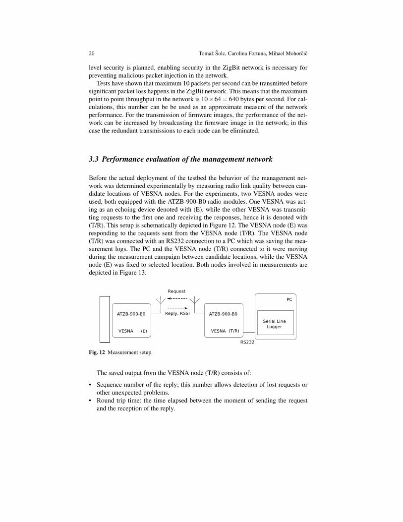
Before the actual deployment of the testbed the behavior of the management net-work was determined experimentally by measuring radio link quality between can-didate locations of VESNA nodes. For the experiments, two VESNA nodes wereused, both equipped with the ATZB-900-B0 radio modules. One VESNA was act-ing as an echoing device denoted with (E), while the other VESNA was transmit-ting requests to the first one and receiving the responses, hence it is denoted with(T/R). This setup is schematically depicted in Figure 12. The VESNA node (E) wasresponding to the requests sent from the VESNA node (T/R). The VESNA node(T/R) was connected with an RS232 connection to a PC which was saving the mea-surement logs. The PC and the VESNA node (T/R) connected to it were movingduring the measurement campaign between candidate locations, while the VESNAnode (E) was fixed to selected location. Both nodes involved in measurements aredepicted in Figure 13.
Fig. 12 Measurement setup.
The saved output from the VESNA node (T/R) consists of:
• Sequence number of the reply; this number allows detection of lost requests orother unexpected problems.
• Round trip time: the time elapsed between the moment of sending the requestand the reception of the reply.

Low-cost testbed development and its applications in cognitive radio prototyping 21
Fig. 13 VESNA node (T/R) with a PC on a mobile measurement platform (left) and VESNA node(E) at a fixed location (right).
• Received Signal Strength Indicator (RSSI): the power level of the received reply,measured in dBm.
• Link Quality Indicator (LQI): value showing the power and the amount of distor-tion in the frames received by the radio [15]. Because the ATZB-900-B0 modulesare internally implemented with an AVR microcontroller (ATmega1281) and anAT86RF212 radio, the LQI obtained from the modules is expected to correspondto the LQI of the AT86RF212 radio, as presented in the radio’s datasheet [17].
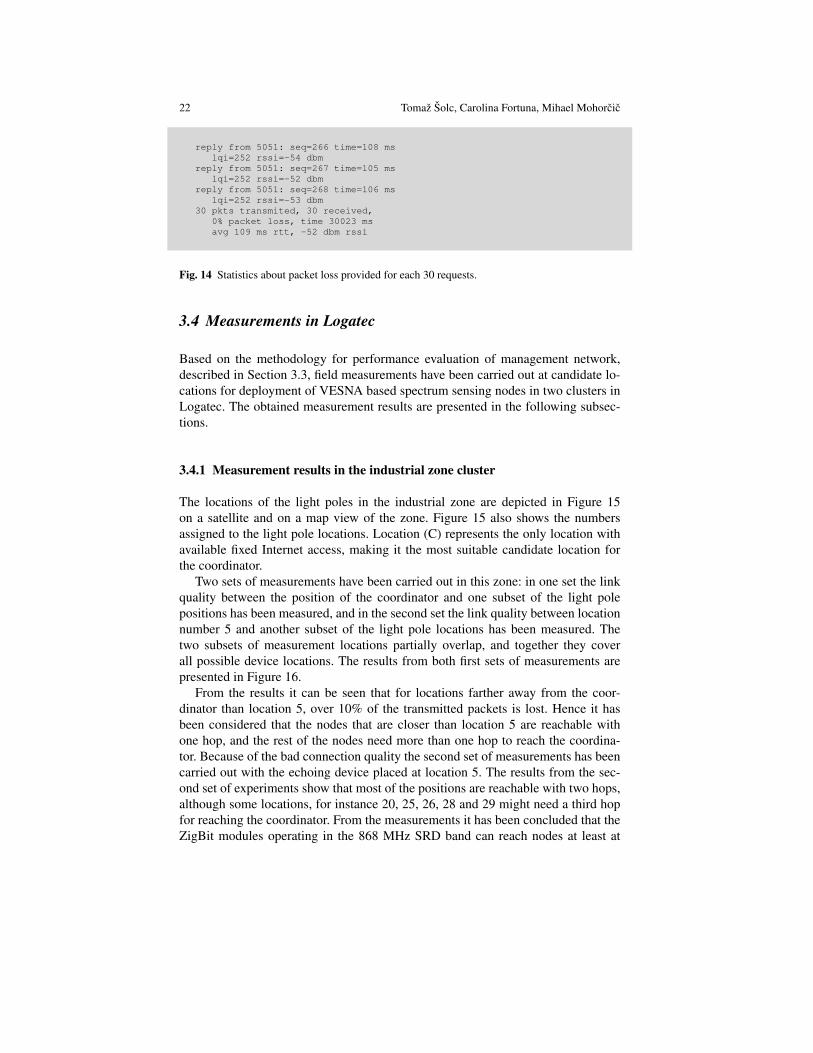
For every 30 requests, the VESNA node (T/R) printed the statistics about packetloss, time needed for measurements, average round trip time and RSSI. A represen-tative part of the output from the VESNA node (T/R) is presented in Figure 14.
This data was complemented by a measurement location record in terms of GPScoordinates obtained by a dedicated GPS receiver, a GPSMAP 60CS device pro-duced by Garmin.
22 Tomaz Solc, Carolina Fortuna, Mihael Mohorcic
reply from 5051: seq=266 time=108 mslqi=252 rssi=-54 dbm
reply from 5051: seq=267 time=105 mslqi=252 rssi=-52 dbm
reply from 5051: seq=268 time=106 mslqi=252 rssi=-53 dbm
30 pkts transmited, 30 received,0% packet loss, time 30023 msavg 109 ms rtt, -52 dbm rssi
Fig. 14 Statistics about packet loss provided for each 30 requests.
3.4 Measurements in Logatec
Based on the methodology for performance evaluation of management network,described in Section 3.3, field measurements have been carried out at candidate lo-cations for deployment of VESNA based spectrum sensing nodes in two clusters inLogatec. The obtained measurement results are presented in the following subsec-tions.
3.4.1 Measurement results in the industrial zone cluster
The locations of the light poles in the industrial zone are depicted in Figure 15on a satellite and on a map view of the zone. Figure 15 also shows the numbersassigned to the light pole locations. Location (C) represents the only location withavailable fixed Internet access, making it the most suitable candidate location forthe coordinator.
Two sets of measurements have been carried out in this zone: in one set the linkquality between the position of the coordinator and one subset of the light polepositions has been measured, and in the second set the link quality between locationnumber 5 and another subset of the light pole locations has been measured. Thetwo subsets of measurement locations partially overlap, and together they coverall possible device locations. The results from both first sets of measurements arepresented in Figure 16.
From the results it can be seen that for locations farther away from the coor-dinator than location 5, over 10% of the transmitted packets is lost. Hence it hasbeen considered that the nodes that are closer than location 5 are reachable withone hop, and the rest of the nodes need more than one hop to reach the coordina-tor. Because of the bad connection quality the second set of measurements has beencarried out with the echoing device placed at location 5. The results from the sec-ond set of experiments show that most of the positions are reachable with two hops,although some locations, for instance 20, 25, 26, 28 and 29 might need a third hopfor reaching the coordinator. From the measurements it has been concluded that theZigBit modules operating in the 868 MHz SRD band can reach nodes at least at

Low-cost testbed development and its applications in cognitive radio prototyping 23
Fig. 15 Satellite (left) and map view (right) of measurement locations in the industrial zone ofLogatec. Location designations are given in parentheses.
Fig. 16 RSSI and packet loss in the industrial zone measured between light poles and the coor-dinator’s location (top and bottom left) and measured between light poles and location number 5(top and bottom right).

24 Tomaz Solc, Carolina Fortuna, Mihael Mohorcic
5 light poles away. These estimates are pessimistic because the measurement havebeen carried out at approximately 1.2 metres above the ground level, whereas nodeswere to be installed on the public light poles at approximately 4-5 metres above theground level, where propagation conditions are expected to be more favourable.
3.4.2 Measurement results in the City center cluster
Fig. 17 Satellite (top) and map view (bottom) of measurement locations in the center of Logatec.Location designations are given in parentheses.
The locations of the light poles in the center of Logatec are presented in Figure17. The numbers on the map represent the numbers given to the public light poles inthe center of Logatec. The location marked with (C) shows the preferred candidatelocation for the coordinator, providing fixed Internet access. The public light polesin the center are installed more densely than in the industrial zone.

Low-cost testbed development and its applications in cognitive radio prototyping 25
Similar as in the industrial zone, also in the center of Logatec two sets of mea-surements have been carried out. In one set the link quality from the location of thecoordinator towards most of the other possible locations has been estimated, and inthe second one the link from location number 25 towards the rest of the public lightpoles in the zone has been estimated.
Fig. 18 RSSI and packet loss in the center of Logatec measured between light poles and the coor-dinator’s location (top and bottom left) and measured between light poles and location number 25(top and bottom right).
The results of the two measurement sets are shown in Figure 18. From the firstset of measurements it can be seen that the coordinator has a good quality link to allof the devices installed along the central street of Logatec. The only location wheremore than 10% packet loss has been measured is location 20. After performing themeasurement of links pointing to the coordinator’s location, the echoing device hasbeen moved to location 25, from where good link quality was expected towardsthe rest of the possible locations of devices. The second set of results shown inFigure 18 confirms the good link quality towards locations 26-34. Based on thesemeasurements, all nodes from the cluster in the center of Logatec are expected to beat most two hops distance from the coordinator of the cluster.
3.4.3 Selecting device locations for testbed deployment
ZigBit modules used in the LOG-a-TEC testbed for the management network forma network with a tree topology starting from the coordinator as the root of the tree.Based on the measurement results given in Sections 3.4.1 and 3.4.2 the maximumhop count in network when communicating with the gateway is expected to be 3 or4 hops in the case of the industrial zone and 2 hops for the center of Logatec, so the

26 Tomaz Solc, Carolina Fortuna, Mihael Mohorcic
proper functioning of the ZigBit modules and the automatic build-up of the ZigBitnetwork is expected.
From the measurements it can be seen that for the industrial zone cluster thecommunication range in the 868 MHz SRD frequency band is at least 5 light poles,and even larger for the city center with more dense public light poles. This meansthat VESNA nodes with SNE-ISMTV-TI868 operating in the 868 MHz SRD bandcan be installed on every third light pole, without affecting the sensing performancesignificantly. VESNA nodes with SNE-ISMTV-TI2400 operating in the 2.4 GHzISM band have been installed every second light pole or closer, because they havesmaller reception and transmission range. TV transmissions in the UHF frequencyband are constant and the locations of the transmitter towers are known, so it isenough to install only a few UHF band TV receivers in the two clusters of thetestbed.
Fig. 19 Device types deployed in Logatec industrial zone (left) and city center (right).
Based on the observations from above, the light pole allocations depicted in Fig-ure 19 have been created for the industrial zone and for the city center. On bothfigures the striped, white and shaded markers with a dot indicate the locations ofthe 868 MHz SRD band, 2.4 GHz ISM band and the UHF band sensing nodes, re-spectively, and the white markers without a dot show locations reserved for futureexpansion of the testbed. The locations of the two coordinators are not shown ex-plicitly, although their locations can be easily found from Figure 15 and Figure 17and they coincide with the locations of the UHF band sensing nodes.
As it can be seen from Figure 19, three VESNA nodes with SNE-ISMTV-UHFreceivers are planned for the industrial zone, and four for the city center. The loca-tions of the TV receivers are evenly distributed along the area of the testbed. For therest of the locations, in the industrial zone the pattern of one sensor for 868 MHzSRD band and two sensors for 2.4 GHz ISM band is repeated, while in the center

Low-cost testbed development and its applications in cognitive radio prototyping 27
the 868 MHz and 2.4 GHz ISM band sensors are assigned to light poles in an al-ternating manner. This way 14 sensors for 2.4 GHz ISM band were installed in theindustrial zone and 15 in the city center, whereas for 868 MHz SRD band sensing 9and 7 sensors were installed in the industrial zone and in the city center, respectively.The reserved locations are marked on the maps because the public light poles arepowered in groups, so the reserved locations will have to be powered in any case.Knowing that power is already available at some locations is useful for the futureexpansion of the testbed.
3.5 LOG-a-TEC testbed access, control and reconfiguration
Remote access to and configuration of nodes in a testbed is supported through thewired or wireless management network. In case of the VESNA-based testbed themanagement network among nodes is based on ZigBee, as implemented in the Zig-Bit port to Atmel modules. It forms a wireless multihop network, which means thegateway is able to communicate also with the nodes out of its direct radio range.
For the purpose of communication between sensor network and the remote server(infrastructure side) we developed a new protocol (see Figure 20), which was in-spired by the HTTP protocol and is simple enough for fast implementation onVESNA nodes. The protocol defines two types of requests, GET and POST, whichare understood by every VESNA node. The GET is used for safe requests which donot change the state of the system and POST for unsafe requests which change thestate of the system. The response from a node following a GET request is consid-ered to be in binary format and handled accordingly, although general responses arein text format and only the spectrum sensing data is in binary format. The ending ofeach response is indicated with the sequence OK\r\n.
The protocol includes simple but efficient error handling mechanism. There aretwo types of errors defined. The first is JUNK-INPUT, which is the more commonsituation when the resource name is mistyped and the parser on the node does notrecognize it. The second type of error is CORRUPTED-DATA, used when cyclicredundancy check (CRC) check did not succeed thus we can conclude that the errorhappened somewhere on the line between the infrastructure and the gateway. Thelast situation will occur with very low probability.
The protocol is designed as a client-server protocol. In our case the server side ison sensor nodes and the client side is on the remote server. Before we can access theresources the gateway has to establish a connection with the infrastructure side. Thisis done by establishing a secure SSL encrypted socket with the remote server. Thegateway has an Ethernet module embedded on the expansion board which is usedto connect the gateway to the internet. The Ethernet module is configured to get theIP address from DHCP server and then automatically tries to set up an encryptedSSL socket with one of the SSL servers listening on a specific port located on theremote server. Once the connection has been established one could access any re-source (sensor, radio module, etc.) or procedure on any of the nodes. Procedures

28 Tomaz Solc, Carolina Fortuna, Mihael Mohorcic
GET:GET resource?arg1=val1&arg2=val2&...&argN=varN\r\n
resource: abstract resource identifierexamples: - firmare/version
- sensors/temperaturearg1: parameter 1 nameval1: value of parameter 1...argN: parameter N namevalN: value of parameter N
POST:POST resource?arguments\r\nLength=len\r\n<data, having len bytes length>\r\ncrc=crc_value\r\n
resource: abstract resource, e.g. firmwarearguments: arguments given to the handler of POSTexample: 2.34/firmwarelen: length of the data that will be written to
the specific resourcedata: possibly binary data, to be transmittedcrc_value: value of CRC calculated on all the previous
content except the line starting with crc=;value represented as an unsigned decimalnumber
Responses from the coordinator have the general form:
<response to a specific request>\r\nOK\r\n
Fig. 20 Resource access protocol.
pre-prepared on the nodes include remote reprogramming, start spectrum sensing,collect spectrum data, configure nodes as transmitters, configure frequency band,etc.
3.6 Summary
This section presents the testbed and management network planning performed forthe LOG-a-TEC testbed, taking into account high-level goals of the testbed andthe constraints and performance requirements of the management network. Themethodology for performance evaluation of the network used in the planning ofthe testbed is presented, and results from actual field measurements are providedand analysed, justifying the selection of device locations and their distribution inthe LOG-a-TEC testbed as per sensing functionality. Section concludes with the de-scription of the protocol used for remote access, control and configuration of the

Low-cost testbed development and its applications in cognitive radio prototyping 29
LOG-a-TEC testbed making use of the underlying management network based onAtmel’s ZigBit network.
4 Signal generation use case
The LOG-a-TEC testbed presented in previous sections can be used for differentexperiments in communications, facilitating the transition of technology from fullycontrolled computer simulation environments to actual prototyping. As explainedin Section 2, the main role of VESNA nodes equipped with the SNE-ISMTV ex-pansion boards is spectrum sensing, and as deployed in the LOG-a-TEC testbedthey can perform distributed spectrum sensing. However, investigation of primary-secondary scenarios requires also controlled emulation of primary users, especiallywireless microphones. To remove the need to manually introduce wireless micro-phones into the testbed during the experimentation, VESNA nodes can also supportremotely controlled emulation of wireless microphone transmissions. In particu-lar, this has been enabled on VESNA nodes equipped with the SNE-ISMTV-TI868transceiver, that is capable of transmitting a narrow-band signal at frequencies be-tween 780 MHz and 862 MHz. This frequency span includes the upper UHF chan-nels that are used by licensed wireless microphone users. In LOG-a-TEC, one ormore of these nodes can be remotely triggered to act as wireless microphones dur-ing the experiment or demonstration.
To create as realistic environment as possible in the testbed it was decided to usethe IEEE wireless microphone emulation profiles [18]. This method approximates aradio signal transmitted by a legacy analogue studio wireless microphone (PMSE)using a frequency modulated continuous sine wave s(t).
s(t) = Acos(
2π fct +fdev
fmcos(2π fmt)
)(1)
In Equation 1, A is the carrier amplitude, fc is the carrier frequency (between780 and 862 MHz), fdev is the frequency deviation and fm is the frequency of thecontinuous sine wave base band signal. Three signal profiles are defined in literatureas summarised in Table 4, i.e. silent, soft speaker and loud speaker. Each profile cor-responds to one typical operating condition of the wireless microphone and definesthe values for fdev and fm.
Operating mode fm [kHz] fdev [kHz]Silent 32.0 5.0Soft 3.9 15.0Loud 13.4 32.6
Table 4 FM parameters for wireless microphone simulation profiles.

30 Tomaz Solc, Carolina Fortuna, Mihael Mohorcic
The SNE-ISMTV-868 transceiver is not directly capable of transmitting a mod-ulated analogue signal as required by this method. However it contains a digitalfrequency-shift keying modulator block with 4 symbols (4FSK) that can be used totransmit a continuous signal. In FSK each symbol is represented by a sine with a fre-quency that is shifted from the carrier frequency by a discrete amount, determinedby the symbol value. When fed with an appropriate stream of symbols at a highenough rate, such a modulator can be used to approximate an analogue waveform,as depicted in Figure 21.
-2
-1.5
-1
-0.5
0
0.5
1
1.5
2
0 1 2 3 4 5 6
Fig. 21 Approximating a sine wave with frequency-shift keying transmission. Dotted line depictsan ideal analogue signal while the bold line shows an approximation achievable with a 4FSKmodulator.
Using the 4FSK modulator an approximation was hence implemented of thewireless microphone emulation profiles. The block diagram of the implementationis depicted in Figure 22. The transceiver was configured for 200 ksymbols/s, whichwas the maximum symbol rate that was achievable on the VESNA core CPU run-ning at 64 MHz. This is was equivalent to a transmission of a sampled analoguesignal with 2-bit quantization and fs = 200 kHz sampling rate. The continuoussymbol stream was provided by the VESNA core CPU to the transceiver througha synchronous serial bus.
To generate the appropriate symbol stream for the modulator hardware block adirect digital synthesis (DDS) algorithm was implemented in software on the CPU.A DDS consists of a phase accumulator, a tuning word TW register and a table oflength L that maps between phase value in the desired signal amplitude. For eachsignal amplitude value emitted by the DDS algorithm, the value of the tuning wordis added to the phase accumulator. Hence the frequency of the baseband signal fmcan be adjusted by software simply by setting an appropriate tuning word value,according to Equation 2.

Low-cost testbed development and its applications in cognitive radio prototyping 31
TW = Lfm
fs(2)
In our case an output coder was also required to map the signal amplitude to theappropriate 4FSK symbol. Best mappings between signal amplitude and 4FSK sym-bol were determined experimentally, as they were not provided by the manufacturerof the transceiver.
To set the frequency deviation fdev according to Table 4, the hardware FSK mod-ulator deviation setting was adjusted by writing to the appropriate transceiver hard-ware register. By adjusting these two settings (FSK deviation and tuning word) wewere able to closely match the FM parameters required for all three wireless micro-phone simulation profiles. An example of the spectrum for the VESNA-emulatedwireless microphone signal corresponding to a loud speaker compared to the samesignal produced by a USRP device is depicted in Figure 232.
Fig. 22 Block diagram of Direct Signal Synthesis on VESNA with SNE-ISMTV expansion.
The three supported wireless microphone emulation profiles are available in allVESNA nodes with the SNE-ISMTV-TI868 transceiver in the LOG-a-TEC testbedand were seamlessly integrated with the signal generation API, which is exposed bysensor nodes. To cover the entire UHF frequency band two configurations were re-quired for each emulation profile due to the limitation on the number of channels per
2 The program source code for the wireless microphone emulation is available at https://github.com/avian2/vesna-audio-synthesis

32 Tomaz Solc, Carolina Fortuna, Mihael Mohorcic
Fig. 23 Spectrum of a loud speaker wireless microphone simulation signal produced by SNE-ISMTV (upper, thick trace) compared to the same signal produced by a USRP device (lower, thintrace).
hardware transceiver configuration (256). Hence when queried for signal generationprofiles (see Figure 24), these nodes report 6 wireless microphone signal generationconfigurations.
4.1 Summary
SNE-ISMTV-UHF is a low cost custom designed receiver only and therefore unableto transmit in VHF and UHF bands. In order to support the emulation of wirelessmicrophone for LOG-a-TEC, the SNE-ISMTV-TI868 extension board was used toenable generating wireless microphone profiles that are compliant with the IEEErequirements. This functionality can be used in a coexistence study of incumbentand cognitive radio systems in the TV white spaces, as for example in the CREW-TV project concerned with the investigation of the benefits of combining a TVWSdatabase with a distributed sensing network.

Low-cost testbed development and its applications in cognitive radio prototyping 33
GET nodes?8/generator/deviceConfigListdev #0, CC1100, 9 configs:cfg #0: CC1100, FM noise, 200 kHz deviation:
base: 779999908 Hz, spacing: 199814 Hz, bw: 197754 Hz, channels: 256,min power: -30 dBm, max power: 12 dBm, time: 5 ms
cfg #1: CC1100, FM noise, 200 kHz deviation:base: 829999924 Hz, spacing: 199814 Hz, bw: 197754 Hz, channels: 160,min power: -30 dBm, max power: 12 dBm, time: 5 ms
cfg #2: CC1100, wireless mic, silent:base: 779999908 Hz, spacing: 199814 Hz, bw: 197754 Hz, channels: 256,min power: -30 dBm, max power: 12 dBm, time: 5 ms
cfg #3: CC1100, wireless mic, silent:base: 829999924 Hz, spacing: 199814 Hz, bw: 197754 Hz, channels: 160,min power: -30 dBm, max power: 12 dBm, time: 5 ms
cfg #4: CC1100, wireless mic, soft speaker:base: 779999908 Hz, spacing: 199814 Hz, bw: 197754 Hz, channels: 256,min power: -30 dBm, max power: 12 dBm, time: 5 ms
cfg #5: CC1100, wireless mic, soft speaker:base: 829999924 Hz, spacing: 199814 Hz, bw: 197754 Hz, channels: 160,min power: -30 dBm, max power: 12 dBm, time: 5 ms
cfg #6: CC1100, wireless mic, loud speaker:base: 779999908 Hz, spacing: 199814 Hz, bw: 197754 Hz, channels: 256,min power: -30 dBm, max power: 12 dBm, time: 5 ms
cfg #7: CC1100, wireless mic, loud speaker:base: 829999924 Hz, spacing: 199814 Hz, bw: 197754 Hz, channels: 160,min power: -30 dBm, max power: 12 dBm, time: 5 ms
cfg #8: CC1100, 868 MHz SRD band, FM noise, 50 kHz deviation:base: 863999695 Hz, spacing: 49953 Hz, bw: 49438 Hz, channels: 140,min power: -30 dBm, max power: 12 dBm, time: 5 ms
Fig. 24 The profiles currently supported by the VESNA SNE-ISMTV-TI868 in LOG-a-TEC.
5 An interference mitigation use case
The use case presented in Section 4 demonstrates how the LOG-a-TEC testbed, oreven individual VESNA nodes, can be used to support the investigation of coexis-tence of primary and secondary users in TVWS, while the use case in this sectiondemonstrates the use of the testbed for investigation of approaches to coexistenceof secondary devices in shared radio spectrum. In such use case the experimenteris faced with real-world problems and challenges with the implementation of theinvestigated approach or algorithm that have to be appropriately addressed. In thefollowing we show an example of a game theoretic approach to cognitive radiowith power allocation and interference mitigation game with more detailed insightsavailable in [19].
Game theoretic approaches to the problem of resource management in wirelesscommunications have been extensively studied over the last decade as they providea more flexible and dynamic alternative to co-existence and resource sharing. Oneof the simplest forms of co-existence is coordinating the interference among severaltransmitters by limiting the transmit power. For instance, in [20], the authors proposea theoretical framework for a game-theoretic power control scheme for wireless andad-hoc networks. In [21], the authors reformulate the problem by also consideringenergy efficiency alongside with interference and propose the ProActive Power Up-

34 Tomaz Solc, Carolina Fortuna, Mihael Mohorcic
date (PAPU) algorithm. Simulation results showed that PAPU can utilize energymore efficiently by sacrificing a small amount of network utility compared to theAsynchronous Distributed Pricing (ADP) protocol proposed in [20]. An exampleuse case enabled by the LOG-a-TEC testbed is to evaluate the PAPU algorithm in arealistic outdoor scenario.
5.1 Summary of the PAPU algorithm
The power allocation game proposed in [21] is formulated as follows. Given a wire-less network of N transmit-receive pairs (T xi-Rxi), where a ”pair” is referred to asa ”player”, the objective is to find stable points of power allocation for each playersuch that the players’ global utility is maximum while the cumulated power levelsare kept to a minimum.
More formally, given a set of N players, N = 1,2, ...,N, and their correspond-ing power allocation profile P = p1, p2, ..., pN, the utility function of each playeris given by:
ui = log(1+hii pi
n0 +1B ∑ j 6=i h ji p j
) (3)
where pi, p j are the transmit powers of players i and j, hii is the direct gain, h ji is thechannel gain between transmitter j and receiver i, B is the total channel bandwidthand n0 is the noise power. For simplicity and in accordance to [21], we consider B=1.Now, the objective is to maximize the global utility function (4a), while minimizingthe globally allocated power (4b) where pi ∈ [0,Pmax
i ].
max∑i
ui (4a)
min∑i
pi (4b)
In the evaluations performed in a simulation environment [21], the values for thedirect gain, the cross gains, the transmitted power and noise were chosen conve-niently to provide the proof of concept. Communication and reconfiguration delaywere not taken into account.
The validation of theoretical models in real-world set-ups poses several con-straints that are most often testbed specific. We employed the following method-ology for investigating the feasibility of experimenting with interference mitigationbased on the power allocation game in LOG-a-TEC:
• Identification of the experimental set-up and the constraints.• Adaptation of the theoretical framework for the use in a testbed rather than in a
simulation scenario.• Empirical determination of the values of parameters such as channel gain.• Implementation and experimental evaluation.

Low-cost testbed development and its applications in cognitive radio prototyping 35
5.2 Experimental set-up
After identifying and understanding the theoretical framework we desire to validate,the next step is to understand the constraints imposed by the testbed we plan touse. These constraints will require an adaptation of the framework so that it can bevalidated in a realistic set-up. For the case of LOG-a-TEC, the following constraintscan be identified:
• Topological - The topology of the testbed is determined by the alignment of thepublic light poles on which the sensor nodes are mounted. The theoretical frame-work behind PAPU assumes that the cross gains are significantly smaller thanthe direct gains. If this constraint is not satisfied, the game might not converge.This constraint and the topology of the testbed narrows down the choice for thelocation of the players.
• Transmission capability - The testbed nodes are able to transmit on one channelat a time, therefore limiting the type of games that can be supported to singlechannel ones.
• Power levels - The nodes’ CC2500 transceivers support discrete power levels.Unlike in the theoretical framework, where continuous power levels are consid-ered, the empirical game has to be adjusted to one of the associated power levelsspecified by the radio chip. This clearly affects players’ strategies as well as theresulting stable points of power allocation for players.
• Sensing - The nodes in the testbed use energy detection for spectrum sensing.This simple method cannot distinguish between different types of detected sig-nals. As a result, the accuracy of the measurements is lower, therefore transmitpower level adaptations of the players may be misguided by errors.
• Delay - The delay for setting up a transmission or a sensing vary depending onthe nodes, since the management network through which this setup is conductedis wireless. Typical values for this setting are from 1 to 3 seconds. The delayaffects the speed of the game, thus the time required to converge.
• Synchronization - The nodes in the testbed do not use a clock synchronizationprotocol, therefore the lack of synchronization has to be taken into account whendesigning and implementing the game.
• Calibration - The low cost nodes are not calibrated, therefore a setting of 0dBm transmission power might result in a slight shift of the level of the actualtransmitted power. This affects the final strategies of the players.
Considering the theoretical framework behind the PAPU algorithm and the con-straints imposed by the LOG-a-TEC testbed we defined the interference-awarepower control game between two players operating at 2.4 GHz, in the industrialzone cluster. The discrete transmit power levels for the VESNA nodes in LOG-a-TEC can be set to [0, -2, -4, -6, -8, -10, -12, -14, -16, -18, -20, -22, -24, -26, -28, -30, -55] dBm. The two players are transmit-receive pairs coexisting inthe same area, as depicted in Figure 25. Player 1 is formed by the Tx-Rx pairNode25-Node2 whereas player 2 is formed by the Tx-Rx pair Node16-Node17.

36 Tomaz Solc, Carolina Fortuna, Mihael Mohorcic
The distances between the nodes are: d(T X1,RX1) ≈ 50m, d(T X2,RX2) ≈ 65m,d(T X2,RX1)≈ 230m, d(T X1,RX2)≈ 150m.
Fig. 25 Inter-network interference between wireless systems where hi j is the channel gain betweentransmitter i and receiver j. Pentagonal markers point to sensor node locations. Numbers in markersare location identifiers.
5.3 The adaptation of the theoretical framework
The game adopted in this use case is based on players (users) adapting their transmitpower level when detecting a change in other players’ power level. The new transmitpower level, to which a node adapts, is called the best response. The best responseof any of the players involved in the game is given by [21]:
bi(p−i) =1ci−
∑ j 6=i h ji p j +n0
hii=
1ci− I +n0
hii(5)
where bi(p−i) represents the best response of player i given the current state ofthe game (the power profile for all other players is denoted by p−i), ci representsplayer i’s energy cost, hi j are the channel gains, p j is the transmitted power forall the other players and n0 is the noise. In typical controlled evaluation setups,such as simulators, the values for h ji and p j are chosen conveniently to guaranteeconvergence of the game. In a real-world testbed, however, these parameters have tobe acquired from the operating environment and may influence the outcome of thegame. As a result, the following adapted expressions were used in the experimentalevaluation:
bi(p−i) =1ci−
∑ j 6=i h ji p j +n0
h′ii=
1ci−
Prmeasured i−Puse f ul
h′ii(6)
bi(p−i) =1ci−
∑ j 6=i h ji p j +n0
h′ii=
1ci−
Prmeasured|pi=0
h′ii(7)
where h′ii stands for the measured or the measurement-based estimation of the directgain, Prmeasured i stands for the received power measured by player i when player i

Low-cost testbed development and its applications in cognitive radio prototyping 37
is also transmitting (pi 6= 0), Puse f ul stands for the estimated useful power receivedby Rxi when T xi is transmitting, and Prmeasured|pi=0 stands for the received powermeasured by player i when player i’s transmitter is silent (pi = 0).
For the entire system to be stable, the PAPU algorithm must converge to a Nashequilibrium. The convergence issue studied in [21] gives the following condition forthe convergence and stability of PAPU:
|h ji
hii|< 1
N, i = 1, ...,N (8)
Eq. (8) is a decisive factor when choosing the topology of nodes in the testbed onwhich the power allocation game can be implemented. If Eq. (8) is not fulfilled forall players, there will be no strategy profile that will satisfy the players.
In the theoretical case, considering Eq. (5), an equilibrium is reached in the gamewhen pi(t− 1) = pi(t) for all players at once. However, in practice, where pi cantake only discrete values, a more robust stopping criterion is needed in order todetermine the equilibrium. In this study, the criterion is given by the following con-dition: |bi−k(p−i)− bi(p−i)| < Pth, where k = 0,4 and Pth stands for the thresholdpower used to compensate for the environment dynamics.
Based on the PAPU algorithm, we defined the following power control protocol:
• Step 1: Each player i initializes its power p0i , p0−i.
• Step 2: At time t if player i updates its power, player i will alert the neighborsthat a power change has been made.
• Step 3: If player i detects a change in other players’ power, it updates its poweraccording to Eq. (7) and alerts the neighbors of the change.
• Step 4: Player i checks if the Nash equilibrium condition is satisfied• Step 5: If the Nash equilibrium condition is satisfied, the game is stopped.
The code implementing this protocol is too complex to include in this chapter,however it is publicly available in out repository on GitHub 3.
5.4 Empirical parameter determination
The channel estimation for the topology presented in Figure 25 was performed start-ing from empirical data. The gain between pairs of nodes has been measured andthree strategies were investigated for deriving their values for the purpose of thePAPU algorithm, i.e. average gain, instantaneous gain and estimated gain usingKalman filter.
The channel gain was measured as follows. First, the receiver Rx j measured thereceived power Pnoise knowing that the transmitter T xi was silent using the codepresented in Figure 26 lines 1-9 and 15-23. Then, the receiver measured the received
3 https://github.com/sensorlab/logatec-games/blob/master/Power_Allocation_Game/powerAllocation.py

38 Tomaz Solc, Carolina Fortuna, Mihael Mohorcic
power PRx j knowing that the transmitter was transmitting with a given power PT xi
using the code in Figure 26 lines 1-9, 11-19 and 25-27. The gain (lines 29-31 inFigure 26) was then computed according to:
hi j =PRx j −Pnoise
PT xi
(9)
1. # select the pair of nodes2. tx_node = Node(coordinator_id, tx_node_id)3. rx_node = Node(coordinator_id, rx_node_id)4.5. # settings6. p_tx_dBm = 07. sensing_duration = 28. time_after = 1.59. attempts = 010.11. # these lines are needed just for signal measurement12. tx_node.setGeneratorConfiguration(measuring_freq, p_tx_dBm)13. tx_node.generatorStart(time.time(), transmitting_duration)14.15. #configure rx_node16. rx_node.setSenseConfiguration(measuring_freq,17. measuring_freq, 400e3)18. #start sensing19. rx_node.senseStart(time.time()+time_after, sensing_duration, 5)20.21. #these lines are needed just for noise computation22. noise_power = GainCalculations.getAverageDataMeasurementsFromFile(23. coordinator_id ,rx_node.node_id)[1][0]24.25. #these lines are needed just for noise computation26. received_power = GainCalculations.getAverageDataMeasurementsFromFile(27. coordinator_id,rx_node.node_id)[1][0]28.29. #these lines are needed just for gain computation30. gain = (received_power - noise_power) /31. (math.pow(10.00, p_tx_dBm/10.00) * 0.001)
Fig. 26 Example code required to measure the noise between a pair of nodes. (Note: This is ex-ample code, the actual working code is available at https://github.com/sensorlab/logatec-games/blob/master/gain-computation/gainCalculations.py).
Long term channel gain measurements were performed for 19 consecutive days,between August 5th and August 23rd 2013, two times a day, in the afternoon (12:30- 13:30) and late evening (21:00 - 22:00). For channel gain measurements, a signalat 2420 MHz with a bandwidth of 400 kHz was used at the transmitter side. Themeasured direct channel gains for player 1 are represented in a chronological orderin the plot depicted in Figure 27. The vertical white and grey shadings represent theafternoon period with white and the late evening period with gray, respectively.
As shown in Figure 27, the average gain for the pair of nodes representing Player1 is -74.8 dB with a standard deviation of 6.952 dB and a dynamic range of 18.9

Low-cost testbed development and its applications in cognitive radio prototyping 39
Fig. 27 Long term measurements of direct channel gains for player 1 (from August 5th to August23rd 2013 between 12:30 - 13:30 - white vertical shading and 21:00 - 22:00 gray vertical shading).
dB for the 19-day period considered. Even in short term measurement periods, suchas an afternoon or an evening session, gain variations of over 5 dB can be found.Similar observations can be made for other pairs of nodes. The gain is highly dy-namic and thus using the average as a means of approximation does not reflect theactual state of the channel. Therefore the best-response strategy of the power allo-cation game will yield unrealistic values. This method would be suitable if the gainvariation were not considerable (e.g. < 3 dB), which happens only occasionally.
Alternative to average gain as input to the best-response strategy is the the in-stantaneous channel gain. This approach, however, can prove expensive in termsof delay (for the particular case of the LOG-a-TEC testbed one such measurementtakes 5-6 s) and power consumption, and it is prone to measurement errors.
The third approach considered in this use case for deriving the channel gains isto use a simple channel estimation technique such as the Kalman filter. This methodconsists of two steps: the first step is estimating the next measured gain and thesecond step represents the correction of the estimated gain by performing a newgain measurement. The resulting predicted gain is then computed. The values of theKalman predictor for long term measurements are depicted in Figure 27. For a shorthistory, it approximates well the channel gain (see first 3-5 measurements) but itgets worse as the history gets longer.
By analyzing the long-term measurements, three important conclusions reflect-ing the implementation of the game can be drawn. First, the channel gain Kalmanpredictor approach is more suitable for the power allocation game because it com-pensates for the measurement errors to which the instantaneous gain is prone, whilealso relying on measurement history. Second, the Kalman filter based estimationsof the gain are more accurate than the average. This is supported by the smaller val-ues of the mean square error between the Kalman estimations and the instantaneousvalue (K−inst) than the values of the mean square error between average and instan-taneous values (avg−inst) as listed in Table 5. Third, using a shorter history for the
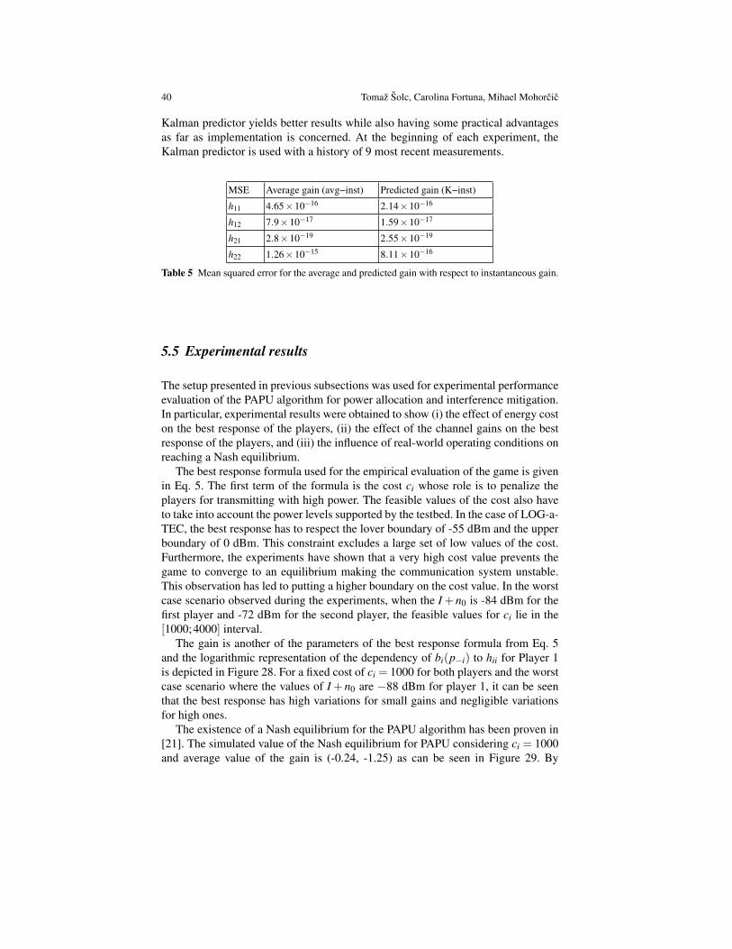
40 Tomaz Solc, Carolina Fortuna, Mihael Mohorcic
Kalman predictor yields better results while also having some practical advantagesas far as implementation is concerned. At the beginning of each experiment, theKalman predictor is used with a history of 9 most recent measurements.
MSE Average gain (avg−inst) Predicted gain (K−inst)
h11 4.65×10⁻¹⁶ 2.14×10⁻¹⁶
h12 7.9×10⁻¹⁷ 1.59×10⁻¹⁷
h21 2.8×10⁻¹⁹ 2.55×10⁻¹⁹
h22 1.26×10⁻¹⁵ 8.11×10⁻¹⁶
Table 5 Mean squared error for the average and predicted gain with respect to instantaneous gain.
5.5 Experimental results
The setup presented in previous subsections was used for experimental performanceevaluation of the PAPU algorithm for power allocation and interference mitigation.In particular, experimental results were obtained to show (i) the effect of energy coston the best response of the players, (ii) the effect of the channel gains on the bestresponse of the players, and (iii) the influence of real-world operating conditions onreaching a Nash equilibrium.
The best response formula used for the empirical evaluation of the game is givenin Eq. 5. The first term of the formula is the cost ci whose role is to penalize theplayers for transmitting with high power. The feasible values of the cost also haveto take into account the power levels supported by the testbed. In the case of LOG-a-TEC, the best response has to respect the lover boundary of -55 dBm and the upperboundary of 0 dBm. This constraint excludes a large set of low values of the cost.Furthermore, the experiments have shown that a very high cost value prevents thegame to converge to an equilibrium making the communication system unstable.This observation has led to putting a higher boundary on the cost value. In the worstcase scenario observed during the experiments, when the I +n0 is -84 dBm for thefirst player and -72 dBm for the second player, the feasible values for ci lie in the[1000;4000] interval.
The gain is another of the parameters of the best response formula from Eq. 5and the logarithmic representation of the dependency of bi(p−i) to hii for Player 1is depicted in Figure 28. For a fixed cost of ci = 1000 for both players and the worstcase scenario where the values of I + n0 are −88 dBm for player 1, it can be seenthat the best response has high variations for small gains and negligible variationsfor high ones.
The existence of a Nash equilibrium for the PAPU algorithm has been proven in[21]. The simulated value of the Nash equilibrium for PAPU considering ci = 1000and average value of the gain is (-0.24, -1.25) as can be seen in Figure 29. By

Low-cost testbed development and its applications in cognitive radio prototyping 41
Fig. 28 The influence of the channel gains on the best response for Player 1 b1(p−1) versus h11and I +n0.
Fig. 29 Experimental Nash equilibrium compared to simulated one for two players.
introducing more realistic gains based on the Kalman estimator, the simulated Nashequilibrium slightly varies around (-0.14, -1.1), as depicted with triangles in Figure29. In this case the influence of the predicted gains to the player’s final strategies isevident.
By running the game on the real−world testbed, the Nash equilibria are morespread as shown with squares in Figure 29, mostly due to interference and noise.Still, the variation of the best response is relatively small with 0.3 dBm for Player1 and 0.5 dBm for Player 2. In the first two cases where simulation was used, theNash equilibrium results in a (0, -2) value. For the case of LOG-a-TEC, in the exper-imental setup, the multitude of Nash equilibria obtained in different runs, after beingrounded to the discrete values of the transmission power supported in LOG-a-TEC,are (0,0) and (0,-2).

42 Tomaz Solc, Carolina Fortuna, Mihael Mohorcic
Fig. 30 Players’ best response as function of players’ costs.
Figure 30 depicts player strategies for different cost schemes. It can be seen thatwith the increase of the cost ci, there is a decrease of the allocated powers. Allthe experiments were performed as following: the channel gains hii were computedat the beginning of each experiment by predicting the gain, interference and noisepower levels. I + n0, were measured and updated at each iteration, k = 0,4 andPth = 0.8 dBm. For Figure 30, all the experiments were repeated 20 times and theNash equilibrium are given as averaged values.
5.6 Summary
This section demonstrated the role of a testbed such as LOG-a-TEC in validatingtechniques proposed for cognitive radios with more detailed insights available in[19]. We selected the ProActive Power Update algorithm based on game theoreticframework, and showed how it can be adapted for validation on LOG-a-TEC. Be-sides validating the proposed framework and algorithms, the effort enabled studyingthe effects of the empirical parameter estimation on the best response and players’strategies which represent the Nash Equilibria. The results showed that for a cer-tain cost range, the system can reach the Nash equilibria. The equilibria and theconvergence time are strongly influenced by the cost but also by the channel gains,requiring special care in selecting the topology of nodes within the testbed.
These results may prove useful in developing new protocols in decentralized CRnetworks and the current implementation is openly available in our repository onGitHub 4.
4 https://github.com/sensorlab/logatec-games

Low-cost testbed development and its applications in cognitive radio prototyping 43
6 Summary of the chapter
In this chapter we described in our view and based on our experience the most im-portant of the aspects related to the design and deployment of the LOG-a-TEC em-bedded, outdoor cognitive radio testbed. We started the chapter by discussing radiofront-end for embedded testbeds and described the SNE-ISMTV expansion boardcustom designed for the VESNA sensor node for supporting cognitive radio exper-imentation with low cost low-power devices. The expansion board can be equippedwith off-the-shelf reconfigurable transceivers for experimentation in license freeSRD and ISM bands at 868 MHz and 2400 MHz, respectively, or with more so-phisticated custom designed hardware operating in VHF and UHF TV bands. Thechapter continues with practical experiences for designing the testbed infrastruc-ture, like the management network and our considerations in the choice of networkprotocols employed in the LOG-a-TEC testbed.
After describing all these aspects of LOG-a-TEC, we provide two use cases thatcan be supported by the testbed. The first one consists of generating a wireless mi-crophone profile for realizing experiments in UHF bands where the correspondingSNE-ISMTV-UHF is only capable of receiving. The wireless microphone profilesare generated using the SNE-ISMTV-TI868 extension and can be used for instanceto perform coexistence experiments where the spectrum sensing data is fed into ahybrid geolocation database. The second use case consists of the validation of aninterference mitigation strategy using a game theoretic framework. The discussionincludes the adaptations required by the theoretical framework as well as discussionwith respect to the constraints posed by the testbed operating in real-world envi-ronment. An evaluation of the approach and discussion related to the trade-offs thatwere observed is also provided.
In summary, the chapter gives a quick insight into the potential for experimen-tally driven research held by embedded testbeds consisting of low cost low-powerdevices. At the same time it points out some important choices one needs to make inthe process of the design, which have significant impact on subsequent usability andfunctionality of the testbed. These especially include the issues related to topologydesign, power supply, network management, remote access and reconfigurability ofdevices.
7 Acknowledgements
The authors would like to thank all our colleagues from SensorLab and the externalcollaborators who contributed directly or indirectly to this book chapter. This workwas partially supported by the FP7 project CREW (FP7-ICT-258301) and by theSlovenian Research Agency through the research grants P2-0016 and J2-4197, andit was contributed also to the COST Action IC0902.

44 Tomaz Solc, Carolina Fortuna, Mihael Mohorcic
References
1. “TmoteSky ultra low power IEEE 802.15.4 compliant wireless sensor mod-ule.” http://www.eecs.harvard.edu/˜konrad/projects/shimmer/references/tmote-sky-datasheet.pdf, Jan. 2014.
2. “VESNA sensor node.” http://sensorlab.ijs.si/hardware.html, Jan. 2014.3. A. Dunkels, B. Gronvall, and T. Voigt, “Contiki-a lightweight and flexible operating system for
tiny networked sensors,” in Local Computer Networks, 2004. 29th Annual IEEE InternationalConference on, pp. 455–462, IEEE, 2004.
4. P. Levis, S. Madden, J. Polastre, R. Szewczyk, K. Whitehouse, A. Woo, D. Gay, J. Hill,M. Welsh, E. Brewer, et al., “TinyOS: An operating system for sensor networks,” in Ambi-ent intelligence, pp. 115–148, Springer, 2005.
5. “CREW - Cognitive Radio Experimentation World.” http://www.crew-project.eu/, Jan. 2014.
6. E. Blossom, “GNU radio: tools for exploring the radio frequency spectrum,” Linux journal,vol. 2004, no. 122, p. 4, 2004.
7. P. D. Sutton, J. Lotze, H. Lahlou, S. A. Fahmy, K. E. Nolan, B. Ozgul, T. W. Rondeau,J. Noguera, and L. E. Doyle, “Iris: an architecture for cognitive radio networking testbeds,”Communications Magazine, IEEE, vol. 48, no. 9, pp. 114–122, 2010.
8. T. Solc, “SNE-ISMTV: VESNA wireless sensor node expansion for cognitive radio experi-ments,” in Wireless Communication Systems (ISWCS 2013), Proceedings of the Tenth Interna-tional Symposium on, pp. 1–2, VDE, 2013.
9. C. A. Boano, J. Brown, Z. He, U. Roedig, and T. Voigt, “Low-power radio communication inindustrial outdoor deployments: The impact of weather conditions and atex-compliance,” inSensor Applications, Experimentation, and Logistics, pp. 159–176, Springer, 2010.
10. S. Lanzisera, A. M. Mehta, and K. S. J. Pister, “Reducing average power in wireless sensor net-works through data rate adaptation,” in Communications, 2009. ICC’09. IEEE InternationalConference on, pp. 1–6, IEEE, 2009.
11. M. Mohorcic, M. Smolnikar, and T. Javornik, “Wireless sensor network based infrastructurefor experimentally driven research,” in Wireless Communication Systems (ISWCS 2013), Pro-ceedings of the Tenth International Symposium on, pp. 1–5, VDE, 2013.
12. “LOG-a-TEC Cognitive radio.” http://log-a-tec.eu/cr.html, Jan. 2014.13. A. Hrovat, I. Ozimek, A. Vilhar, T. Celcer, I. Saje, and T. Javornik, “Radio coverage calcu-
lations of terrestrial wireless networks using an open-source grass system,” Transactions onCommunications, WSEAS, vol. 9, no. 10, pp. 646–657, 2010.
14. T. Solc and Z. Padrah, “Network design for the log-a-tec outdoor testbed,” 2nd InternationalWorkshop on Measurement-based Experimental Research, Methodology and Tools, 2013.
15. “ZigBit 700/800/900 MHz Wireless Modules datasheet.” http://www.atmel.com/Images/doc8227.pdf, Jan. 2014.
16. “Atmel AVR2050: Atmel BitCloud Developer Guide.” http://www.atmel.com/images/doc8199.pdf, Jan. 2014.
17. “AVR Low Power 700/800/900 MHz Transceiver for IEEE 802.15.4-2006, IEEE 802.15.4c-2009, ZigBee, 6LoWPAN, and ISM Applications Data Sheet.” http://www.atmel.com/images/doc8168.pdf, Jan. 2014.
18. C. Clanton, M. Kenkel, and Y. Tang, “Wireless microphone signal simulation method,” IEEE802.22-07/0124r0, 2007.
19. C. Anton, A. Toma, L. Cremene, M. Mohorcic, and C. Fortuna, “Power Allocation Game forInterference Mitigation in a Real-world Experimental Testbed,” in 2014 IEEE InternationalConference on Communications, IEEE, 2014.
20. J. Huang, R. A. Berry, and M. L. Honig, “Distributed interference compensation for wirelessnetworks,” Selected Areas in Communications, IEEE Journal on, vol. 24, no. 5, pp. 1074–1084, 2006.
21. G. Fang, E. Dutkiewicz, K. Yu, R. Vesilo, and Y. Yu, “Distributed inter-network interfer-ence coordination for wireless body area networks,” Global Telecommunications Conference(GLOBECOM 2010), pp. 1–5, 2010.