Embed Size (px)
Citation preview
Low Energy Transfer to the Moon
W.S. Koon∗, M.W. Lo†, J.E. Marsden∗ and S.D. Ross∗
January, 2001
Abstract. In 1991, the Japanese Hiten mission used a low energy transfer with a ballisticcapture at the Moon which required less1V than a standard Hohmann transfer. In this pa-per, we apply the dynamical systems techniques developed in our earlier work to reproducesystematically a Hiten-like mission. We approximate the Sun-Earth-Moon-spacecraft 4-bodysystem as two 3-body systems. Using the invariant manifold structures of the Lagrange pointsof the 3-body systems, we are able to construct low energy transfer trajectories from theEarth which execute ballistic capture at the Moon. The techniques used in the design andconstruction of this trajectory may be applied in many situations.
Keywords: earth-moon transfer, invariant manifolds, three-body problem, space mission de-sign.
1. How to Get to the Moon Cheaply.
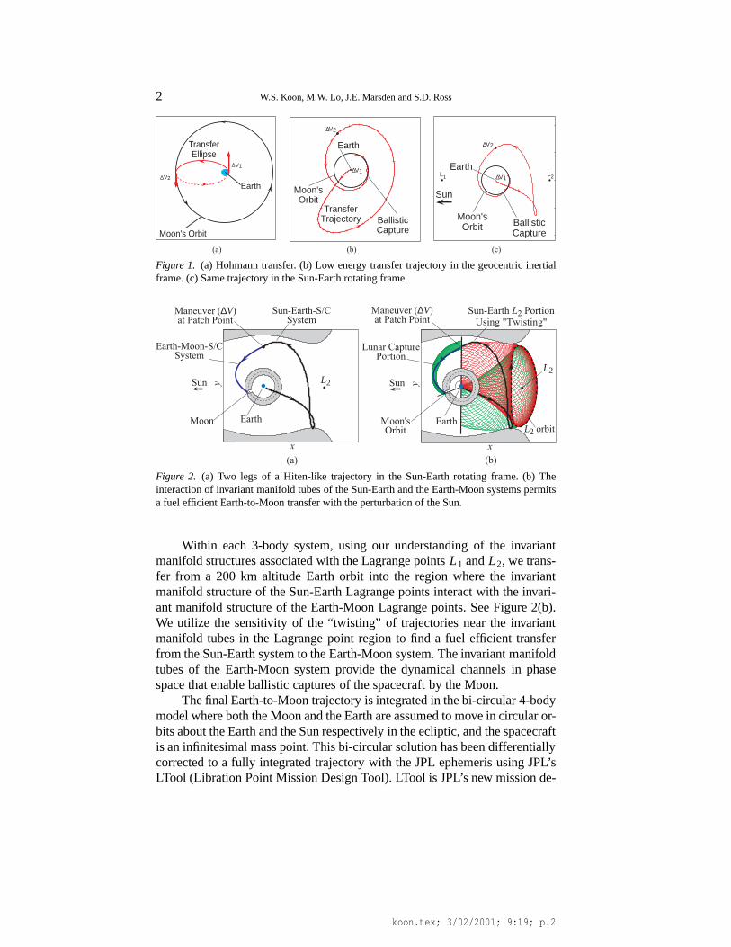
Hiten mission. The traditional approach to construct a spacecraft transfertrajectory to the moon from the Earth is by Hohmann transfer. This type oftransfer uses only 2-body dynamics. It is constructed by determining a two-body Keplerian ellipse from an Earth parking orbit to the orbit of the moon.See Figure 1(a). The two bodies involved are the Earth and a spacecraft. Sucha transfer requires a large1V for the spacecraft to catch up and get capturedby the moon.
In 1991, the Japanese mission, Muses-A, whose propellant budget didnot permit it to transfer to the moon via the usual method was given a newlife with an innovative trajectory design, based on the work of Belbruno andMiller [1993]. Its re-incarnation, renamed Hiten, used a low energy transferwith a ballistic capture at the moon. An Earth-to-Moon trajectory of this type,which utilizes the perturbation by the Sun, requires less fuel than the usualHohmann transfer. See Figures 1(b) and (c).
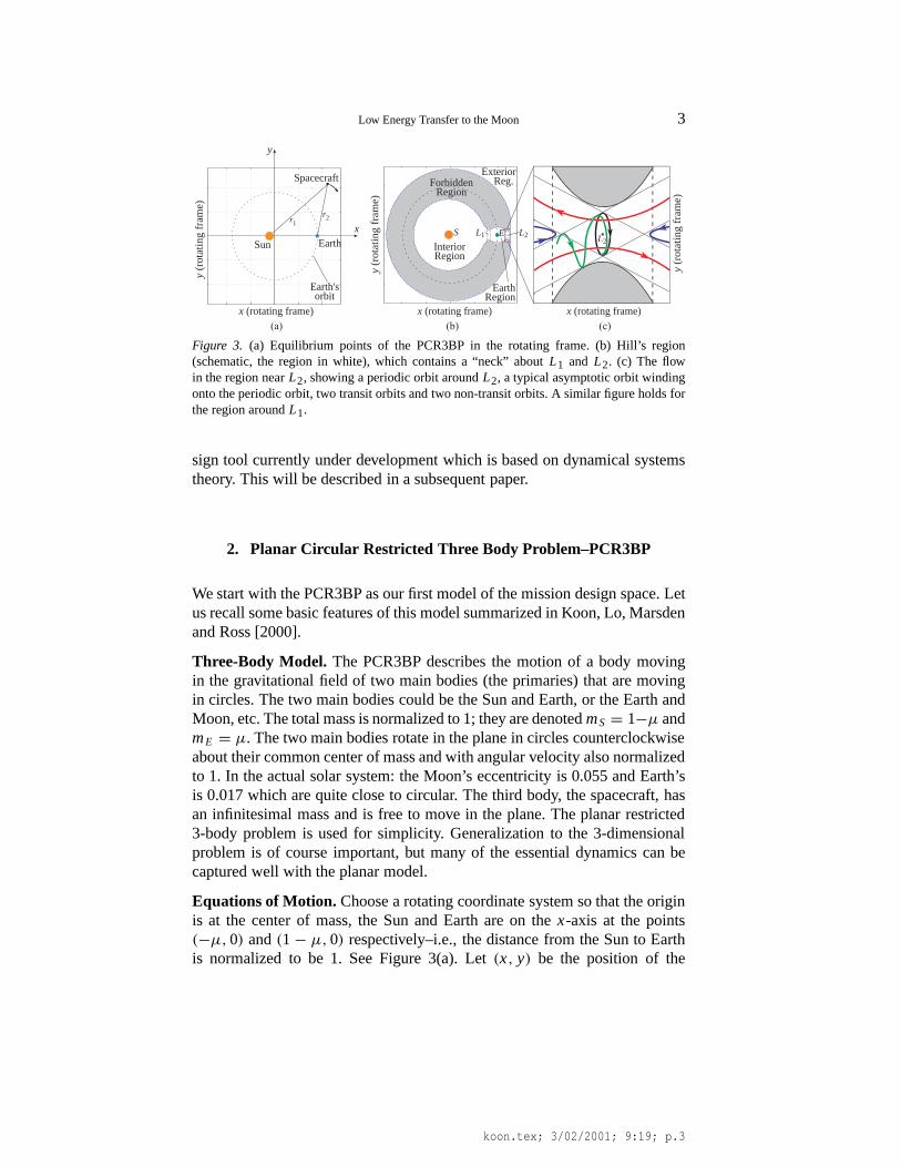
Coupled Three-Body Model.In this paper, we present an approach to theproblem of the orbital dynamics of this interesting trajectory by implementingin a systematic waythe view that the Sun-Earth-Moon-spacecraft 4-bodysystem can be approximated as two coupled 3-body systems. Below is aschematic of this trajectory in the Sun-Earth rotating frame, showing the twolegs of the trajectory: (1) the Sun-Earth Lagrange point portion and (2) thelunar capture portion. See Figure 2(a).
∗ Control and Dynamical Systems, Caltech, Pasadena, California, USA† Navigation and Mission Design, Jet Propulsion Laboratory, Pasadena, California, USA
© 2001Kluwer Academic Publishers. Printed in the Netherlands.
koon.tex; 3/02/2001; 9:19; p.1
2 W.S. Koon, M.W. Lo, J.E. Marsden and S.D. Ross
∆V2
Moon'sOrbit
Earth
BallisticCapture
∆V1
TransferTrajectory
V2∆
∆V1
Earth
L2L1Earth
Moon'sOrbit
Sun
BallisticCapture
∆V2
∆V1
TransferEllipse
Moon's Orbit
(a) (b) (c)
Figure 1. (a) Hohmann transfer. (b) Low energy transfer trajectory in the geocentric inertialframe. (c) Same trajectory in the Sun-Earth rotating frame.
x
ySun
Earth-Moon-S/CSystem
Moon Earth
L2
Maneuver (∆V)at Patch Point
Sun-Earth-S/CSystem
x
y
L2 orbit
Sun
Lunar CapturePortion
Sun-Earth L2 PortionUsing "Twisting"
Moon'sOrbit
Earth
Maneuver (∆V)at Patch Point
(a) (b)
L2
Figure 2. (a) Two legs of a Hiten-like trajectory in the Sun-Earth rotating frame. (b) Theinteraction of invariant manifold tubes of the Sun-Earth and the Earth-Moon systems permitsa fuel efficient Earth-to-Moon transfer with the perturbation of the Sun.
Within each 3-body system, using our understanding of the invariantmanifold structures associated with the Lagrange pointsL1 andL2, we trans-fer from a 200 km altitude Earth orbit into the region where the invariantmanifold structure of the Sun-Earth Lagrange points interact with the invari-ant manifold structure of the Earth-Moon Lagrange points. See Figure 2(b).We utilize the sensitivity of the “twisting” of trajectories near the invariantmanifold tubes in the Lagrange point region to find a fuel efficient transferfrom the Sun-Earth system to the Earth-Moon system. The invariant manifoldtubes of the Earth-Moon system provide the dynamical channels in phasespace that enable ballistic captures of the spacecraft by the Moon.
The final Earth-to-Moon trajectory is integrated in the bi-circular 4-bodymodel where both the Moon and the Earth are assumed to move in circular or-bits about the Earth and the Sun respectively in the ecliptic, and the spacecraftis an infinitesimal mass point. This bi-circular solution has been differentiallycorrected to a fully integrated trajectory with the JPL ephemeris using JPL’sLTool (Libration Point Mission Design Tool). LTool is JPL’s new mission de-
koon.tex; 3/02/2001; 9:19; p.2
Low Energy Transfer to the Moon 3
x (rotating frame)
y (r
ota
ting
fra
me
)
Earth'sorbit
Spacecraft
r1 r2
EarthSun
x
y
x (rotating frame)
y (r
ota
ting
fra
me
)
S EL1
x (rotating frame)x
L2
ExteriorReg.
InteriorRegion
EarthRegion
ForbiddenRegion
(a) (b) (c)
y (r
ota
ting
fra
me
)
LL22
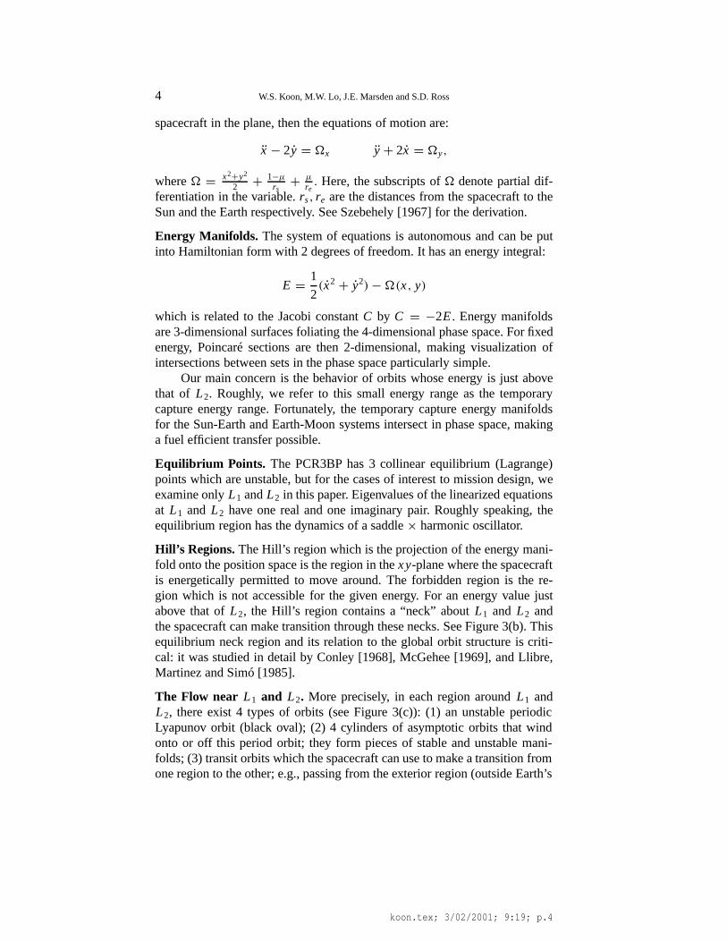
Figure 3. (a) Equilibrium points of the PCR3BP in the rotating frame. (b) Hill’s region(schematic, the region in white), which contains a “neck” aboutL1 and L2. (c) The flowin the region nearL2, showing a periodic orbit aroundL2, a typical asymptotic orbit windingonto the periodic orbit, two transit orbits and two non-transit orbits. A similar figure holds forthe region aroundL1.
sign tool currently under development which is based on dynamical systemstheory. This will be described in a subsequent paper.
2. Planar Circular Restricted Three Body Problem–PCR3BP
We start with the PCR3BP as our first model of the mission design space. Letus recall some basic features of this model summarized in Koon, Lo, Marsdenand Ross [2000].
Three-Body Model. The PCR3BP describes the motion of a body movingin the gravitational field of two main bodies (the primaries) that are movingin circles. The two main bodies could be the Sun and Earth, or the Earth andMoon, etc. The total mass is normalized to 1; they are denotedmS = 1−µ andmE = µ. The two main bodies rotate in the plane in circles counterclockwiseabout their common center of mass and with angular velocity also normalizedto 1. In the actual solar system: the Moon’s eccentricity is 0.055 and Earth’sis 0.017 which are quite close to circular. The third body, the spacecraft, hasan infinitesimal mass and is free to move in the plane. The planar restricted3-body problem is used for simplicity. Generalization to the 3-dimensionalproblem is of course important, but many of the essential dynamics can becaptured well with the planar model.
Equations of Motion. Choose a rotating coordinate system so that the originis at the center of mass, the Sun and Earth are on thex-axis at the points(−µ, 0) and(1 − µ, 0) respectively–i.e., the distance from the Sun to Earthis normalized to be 1. See Figure 3(a). Let(x, y) be the position of the
koon.tex; 3/02/2001; 9:19; p.3
4 W.S. Koon, M.W. Lo, J.E. Marsden and S.D. Ross
spacecraft in the plane, then the equations of motion are:
x − 2y = �x y + 2x = �y,
where� = x2+y2
2 + 1−µ
rs+ µ
re. Here, the subscripts of� denote partial dif-
ferentiation in the variable.rs, re are the distances from the spacecraft to theSun and the Earth respectively. See Szebehely [1967] for the derivation.
Energy Manifolds. The system of equations is autonomous and can be putinto Hamiltonian form with 2 degrees of freedom. It has an energy integral:
E = 1
2(x2 + y2) − �(x, y)
which is related to the Jacobi constantC by C = −2E. Energy manifoldsare 3-dimensional surfaces foliating the 4-dimensional phase space. For fixedenergy, Poincaré sections are then 2-dimensional, making visualization ofintersections between sets in the phase space particularly simple.
Our main concern is the behavior of orbits whose energy is just abovethat of L2. Roughly, we refer to this small energy range as the temporarycapture energy range. Fortunately, the temporary capture energy manifoldsfor the Sun-Earth and Earth-Moon systems intersect in phase space, makinga fuel efficient transfer possible.
Equilibrium Points. The PCR3BP has 3 collinear equilibrium (Lagrange)points which are unstable, but for the cases of interest to mission design, weexamine onlyL1 andL2 in this paper. Eigenvalues of the linearized equationsat L1 and L2 have one real and one imaginary pair. Roughly speaking, theequilibrium region has the dynamics of a saddle× harmonic oscillator.
Hill’s Regions. The Hill’s region which is the projection of the energy mani-fold onto the position space is the region in thexy-plane where the spacecraftis energetically permitted to move around. The forbidden region is the re-gion which is not accessible for the given energy. For an energy value justabove that ofL2, the Hill’s region contains a “neck” aboutL1 and L2 andthe spacecraft can make transition through these necks. See Figure 3(b). Thisequilibrium neck region and its relation to the global orbit structure is criti-cal: it was studied in detail by Conley [1968], McGehee [1969], and Llibre,Martinez and Simó [1985].
The Flow near L1 and L2. More precisely, in each region aroundL1 andL2, there exist 4 types of orbits (see Figure 3(c)): (1) an unstable periodicLyapunov orbit (black oval); (2) 4 cylinders of asymptotic orbits that windonto or off this period orbit; they form pieces of stable and unstable mani-folds; (3) transit orbits which the spacecraft can use to make a transition fromone region to the other; e.g., passing from the exterior region (outside Earth’s
koon.tex; 3/02/2001; 9:19; p.4
Low Energy Transfer to the Moon 5
Moon
L2 orbitEarth
ForbiddenRegion
Tube of TransitOrbits
BallisticCaptureOrbit
x (rotating frame)
y (
rota
ting f
rame)
Passes throughL2 Equilibrium Region
Earth Ends inBallisticCapture
TrajectoryBegins
Inside Tube
x (rotating frame)
y (
rota
ting f
rame)
(a) (b)
Moon L2
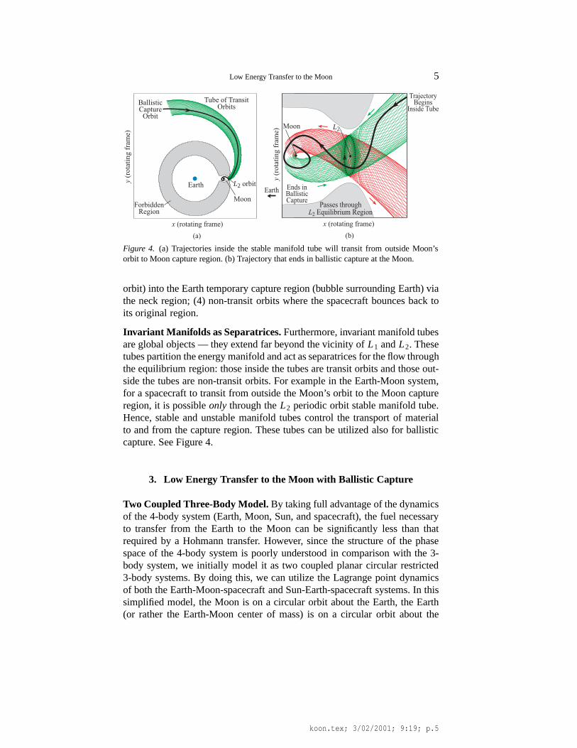
Figure 4. (a) Trajectories inside the stable manifold tube will transit from outside Moon’sorbit to Moon capture region. (b) Trajectory that ends in ballistic capture at the Moon.
orbit) into the Earth temporary capture region (bubble surrounding Earth) viathe neck region; (4) non-transit orbits where the spacecraft bounces back toits original region.
Invariant Manifolds as Separatrices.Furthermore, invariant manifold tubesare global objects — they extend far beyond the vicinity ofL1 andL2. Thesetubes partition the energy manifold and act as separatrices for the flow throughthe equilibrium region: those inside the tubes are transit orbits and those out-side the tubes are non-transit orbits. For example in the Earth-Moon system,for a spacecraft to transit from outside the Moon’s orbit to the Moon captureregion, it is possibleonly through theL2 periodic orbit stable manifold tube.Hence, stable and unstable manifold tubes control the transport of materialto and from the capture region. These tubes can be utilized also for ballisticcapture. See Figure 4.
3. Low Energy Transfer to the Moon with Ballistic Capture
Two Coupled Three-Body Model.By taking full advantage of the dynamicsof the 4-body system (Earth, Moon, Sun, and spacecraft), the fuel necessaryto transfer from the Earth to the Moon can be significantly less than thatrequired by a Hohmann transfer. However, since the structure of the phasespace of the 4-body system is poorly understood in comparison with the 3-body system, we initially model it as two coupled planar circular restricted3-body systems. By doing this, we can utilize the Lagrange point dynamicsof both the Earth-Moon-spacecraft and Sun-Earth-spacecraft systems. In thissimplified model, the Moon is on a circular orbit about the Earth, the Earth(or rather the Earth-Moon center of mass) is on a circular orbit about the
koon.tex; 3/02/2001; 9:19; p.5
6 W.S. Koon, M.W. Lo, J.E. Marsden and S.D. Ross
Sun, and the systems are coplanar. In the actual solar system: the Moon’seccentricity is 0.055, Earth’s is 0.017. and the Moon’s orbit is inclined toEarth’s orbit by 5◦. These values are low, so the coupled planar circular 3-body problem is considered a good starting model. An orbit which becomesa real mission is typically obtained first in such an approximate system andthen later refined through more precise models which include effects such asout-of-plane motion, eccentricity, the other planets, solar wind, etc. However,tremendous insight is gained by considering a simpler model which revealsthe essence of the transfer dynamics.
This is similar to the more standard approach in mission design wherethe solar system is viewed as a series of 2-body problems where Kepleriantheory applies. JPL’s spectacular multiple fly-by missions such as Voyagerand Galileo are based on this Keplerian decomposition of the Solar System.But when one needs to deal with the ballistic capture regime of motion, a3-body decomposition of the Solar System is absolutely necessary.
However, the success of this approach depends greatly on the configu-ration of the specific 4 bodies of interest. In order for low energy transfers totake place, the invariant manifold structures of the two 3-body systems mustintersect within a reasonable time. Otherwise, the transfer may require an im-practically long time of flight. For the Sun-Earth-Moon-spacecraft case, thisis not a problem. The overlap of these invariant manifold structures providethe low energy transfers between the Earth and the Moon.
Construction of Earth-to-Moon Transfer. The construction is done mainlyin the Sun-Earth rotating frame using the Poincaré section0 (along a line ofconstantx-position passing through the Earth). This Poincaré section helpsto glue the Sun-Earth Lagrange point portion of the trajectory with the lunarballistic capture portion. See Figures 7(c) and (d).
The basic strategy is to find an initial condition (position and velocity)for a spacecraft on the Poincaré section such that when integrating forward,the spacecraft will be guided by theL2 Earth-Moon manifold and get ballis-tically captured by the Moon; when integrating backward, the spacecraft willhug the Sun-Earth manifolds and return to Earth.
We utilize two important properties of the Lagrange point dynamics ofthe 3-body problem. The stable manifold tube is key in targeting a captureorbit for the Earth-Moon portion of the design. The twisting of orbits inthe equilibrium region is key in finding a fuel efficient transfer for the Sun-Earth Lagrange point portion of the trajectory. For more details, see Koon,Lo, Marsden and Ross [2000].
Lunar Ballistic Capture Portion. Recall that by targeting the region en-closed by the stable manifold tube of theL2 Lyapunov orbit in the Earth-Moon system, we can construct an orbit which will get ballistically capturedby the Moon. When we transform this Poincaré cut of the stable manifold
koon.tex; 3/02/2001; 9:19; p.6
Low Energy Transfer to the Moon 7
x
y
Sun
BallisticCaptureOrbit
Moon Earth
L2
Tube Containing Lunar Capture Orbits
y (S
un-E
arth
rot
atin
g fr
ame)
.
y (Sun-Earth rotating frame)
Moon's
Orbit
Earth-Moon L2
Orbit StableManifold Cut
Earth
InitialCondition
Poincare Section
InitialCondition
Sun-Earth Rotating Frame
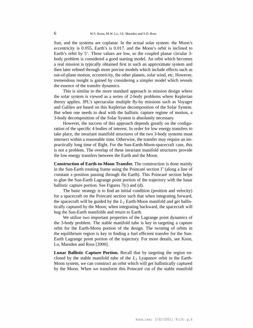
Figure 5. (a) The stable manifold cut of an Earth-MoonL2 orbit in the Poincarè section ofthe Sun-Earth system. (b) A point interior to this cut, with the correct phasing of the Moon,will reach the Moon’s ballistic capture region when integrated forward.
of an Earth-MoonL2 Lyapunov orbit into the Poincaré section of the Sun-Earth system, we obtain a closed curve. A point interior to this curve willapproach the Moon when integrated forward. See Figure 5. Assuming the Sunis a negligible perturbation to the Earth-Moon-spacecraft 3-body dynamicsduring this leg of the trajectory, any spacecraft with initial conditions withinthis closed curve will be ballistically captured by the Moon. “Ballistic cap-ture by the Moon” means an orbit which under natural dynamics gets withinthe sphere of influence of the Moon (20,000 km) and performs at least onerevolution around the Moon. In such a state, a slight1V will result in a stablecapture (closing off the necks atL1 andL2).
Twisting of Orbits and Sun-Earth Lagrange Point Portion Since the twist-ing of orbits in the equilibrium region is key in finding the Sun-Earth La-grange point portion of the design, we would like to review this propertybriefly. In Koon, Lo, Marsden and Ross [2000], we learn that orbits twist inthe equilibrium region following roughly the Lyapunov orbit. The amountof twist of an orbit depends sensitively on its distance from the manifoldtube. The closer to the manifold tube an orbit begins on its approach to theequilibrium region, the more it will be twisted when it exits the equilibriumregion. Hence, with small change in the initial condition (such as a smallchange in velocity at a fixed point), we can change the destination of an orbitdramatically. In fact, we can use this sensitivity to target the spacecraft backto a 200 km Earth parking orbit.
Look at the Poincaré section0 in Figure 6(a). Notice that how a minuteline strip q2q1 of orbits just outside of the unstable manifold cut, when in-tegrated backward, gets stretched into a long stripP−1(q2)P−1(q1) of orbits
koon.tex; 3/02/2001; 9:19; p.7
8 W.S. Koon, M.W. Lo, J.E. Marsden and S.D. Ross
q1
Unstable Manifold
P-1(q2)P-1(q
1)
q2
Stable Manifold
Ear
th
Strip SPre-Imageof Strip S
y-position x-position
y-posi
tion
Earth
L2 orbit
Sun
Earth TargetingUsing "Twisting"
L2
Poincare Section
y-vel
oci
ty
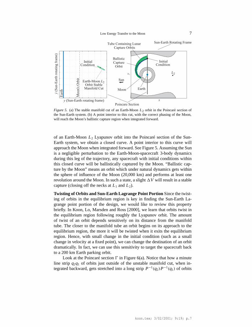
Figure 6. (a) Line stripq2q1 outside of unstable manifold cut gets stretched into a long stripP−1(q2)P−1(q1) that wraps around stable manifold cut. (b) With infinitesimal changes invelocity, any point near lower tube cross-section can be targeted (integrating backward).
that wraps around the whole stable manifold cut. Recall that points onq2q1
represent orbits which have the same position but slightly different velocity.But their pre-imageP−1(q2)P−1(q1) can reach any position on the lower linewhere the stable manifold tube intersects (see Figure 6(b)).
Pick an energy in the temporary capture range of the Sun-Earth systemwhich hasL2 orbit manifolds that come near a 200 km altitude Earth parkingorbit. Compute the Poincaré section0 (see Figure 6(a)). The curve on theright is the Poincaré cut of the unstable manifold of the Lyapunov orbit aroundthe Sun-EarthL2. Picking an appropriate initial condition just outside thiscurve, we can backward integrate to produce a trajectory coming back to theEarth parking orbit.
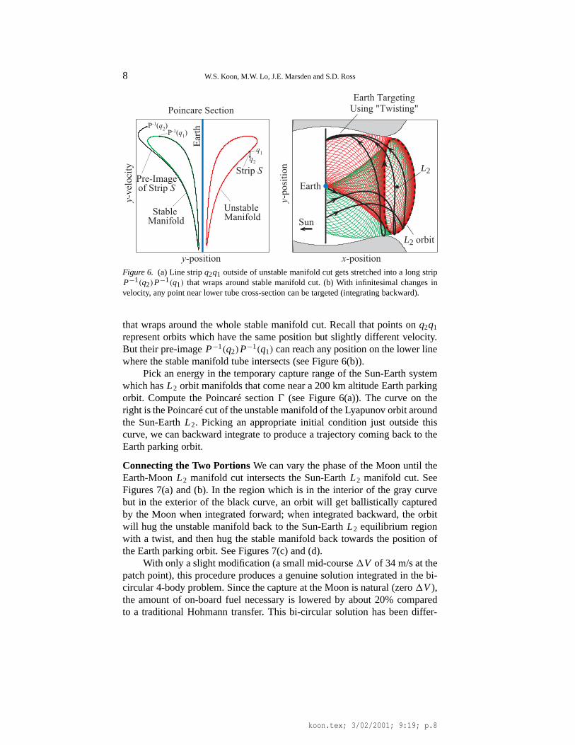
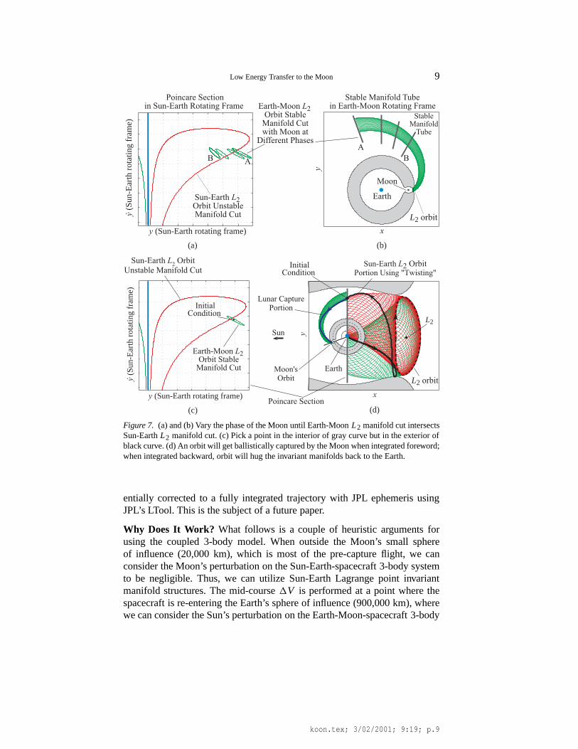
Connecting the Two PortionsWe can vary the phase of the Moon until theEarth-MoonL2 manifold cut intersects the Sun-EarthL2 manifold cut. SeeFigures 7(a) and (b). In the region which is in the interior of the gray curvebut in the exterior of the black curve, an orbit will get ballistically capturedby the Moon when integrated forward; when integrated backward, the orbitwill hug the unstable manifold back to the Sun-EarthL2 equilibrium regionwith a twist, and then hug the stable manifold back towards the position ofthe Earth parking orbit. See Figures 7(c) and (d).
With only a slight modification (a small mid-course1V of 34 m/s at thepatch point), this procedure produces a genuine solution integrated in the bi-circular 4-body problem. Since the capture at the Moon is natural (zero1V),the amount of on-board fuel necessary is lowered by about 20% comparedto a traditional Hohmann transfer. This bi-circular solution has been differ-
koon.tex; 3/02/2001; 9:19; p.8
Low Energy Transfer to the Moon 9
x
y
L2 orbit
Sun
Lunar CapturePortion
Sun-Earth L2 OrbitPortion Using "Twisting"
Moon'sOrbit
Earth
L2
y (S
un-E
arth
rot
atin
g fr
ame)
.
y (Sun-Earth rotating frame)
Earth-Moon L2
Orbit StableManifold Cut
InitialCondition
Sun-Earth L2 Orbit
Unstable Manifold Cut InitialCondition
Poincare Section
y (S
un-E
arth
rot
atin
g fr
ame)
.
y (Sun-Earth rotating frame)
Sun-Earth L2
Orbit UnstableManifold Cut
Poincare Sectionin Sun-Earth Rotating Frame Earth-Moon L2
Orbit StableManifold Cutwith Moon atDifferent Phases
Earth
L2 orbit
Moon
x
y
StableManifoldTube
Stable Manifold Tubein Earth-Moon Rotating Frame
A
BB A
(a) (b)
(c) (d)
Figure 7. (a) and (b) Vary the phase of the Moon until Earth-MoonL2 manifold cut intersectsSun-EarthL2 manifold cut. (c) Pick a point in the interior of gray curve but in the exterior ofblack curve. (d) An orbit will get ballistically captured by the Moon when integrated foreword;when integrated backward, orbit will hug the invariant manifolds back to the Earth.
entially corrected to a fully integrated trajectory with JPL ephemeris usingJPL’s LTool. This is the subject of a future paper.
Why Does It Work? What follows is a couple of heuristic arguments forusing the coupled 3-body model. When outside the Moon’s small sphereof influence (20,000 km), which is most of the pre-capture flight, we canconsider the Moon’s perturbation on the Sun-Earth-spacecraft 3-body systemto be negligible. Thus, we can utilize Sun-Earth Lagrange point invariantmanifold structures. The mid-course1V is performed at a point where thespacecraft is re-entering the Earth’s sphere of influence (900,000 km), wherewe can consider the Sun’s perturbation on the Earth-Moon-spacecraft 3-body
koon.tex; 3/02/2001; 9:19; p.9
10 W.S. Koon, M.W. Lo, J.E. Marsden and S.D. Ross
system to be negligible. Thus, Earth-Moon Lagrange point structures can beutilized for the lunar portion of the trajectory.
Moreover, the fact that the patch point1V is so small and may even beeliminated can be understood by considering the following. From a 200 kmcircular orbit around the Earth, it requires approximately 3150 m/s (providedby the launch vehicle) to reach the Earth-MoonL1 and L2. For another 50m/s, you can reach the Sun-EarthL1 and L2! In other words, a spacecraftneeds roughly the same amount of energy to reach the Sun-Earth and theEarth-MoonL1 and L2. This fortuitous coincidence is what enables theselow energy lunar transfer and capture orbits.
4. Conclusion.
We have laid bare the dynamical mechanism for a Hiten-like mission. Thetheory of Lagrange point dynamics of the 3-body system developed in Koon,Lo, Marsden and Ross [2000] is crucial in understanding this problem. Inmany previous applications of dynamical systems theory to mission design,the focus has been on using the trajectory arcs on the invariant manifolds asinitial guesses for the desired end-to-end trajectory. In this paper, we haveshown that the tubular regions enclosed by the manifolds, the regions exte-rior to the manifolds, as well as the manifolds themselves all may be usedto advantage depending on the desired characteristics of the final trajectory.Mission designers with this knowledge can pick and choose to their hearts’content, an infinite variety of trajectories to suit almost any purpose at hand.
References
Belbruno E.A. and J.K. Miller. Sun-Perturbed Earth-to-Moon Transfers with Ballistic Capture.Journal of Guidance, Control and Dynamics16: 770-775, 1993.
Conley, C. Low Energy Transit Orbits in the Restricted Three-Body Problem .SIAM J. Appl.Math.16: 732-746, 1968.
Koon W.S., M.W. Lo, J.E. Marsden and S.D. Ross. Heteroclinic Connections between Lya-punov Orbits and Resonance Transitions in Celestial Mechanics Ballistic Capture.Chaos10: 427-469, 2000.
Llibre J., R. Martinez, C. Simó. Transversality of the Invariant Manifolds Associated tothe Lyapunov Family of Periodic Orbits Near L2 in the Restricted Three-Body Problem.Journal of Differential Equations58: 104-156, 1985.
McGehee R.P. Some Homoclinic Orbits for the Restricted Three Body Problem.Ph.D. Thesis,University of Wisconsin, Madison, Wisconsin, 1969.
Szebehely, V.Theory of Orbits, The Restricted Problem of Three Bodies, Academic Press,New York and London, 1967.
koon.tex; 3/02/2001; 9:19; p.10