Embed Size (px)
Citation preview
93
iglidur® J
Over 250 sizes available from stock
Low wear against different shaft materials
Low coefficients of friction running dry
Vibration dampening
Good chemical resistance
Best material to use with soft shaft materials
Low moisture absorption
Low friction, low wear: The Fast and Slow Motion Specialist – iglidur® J
94
iglidur® J
More information www.igus.co.uk/en/j
+90º
–50º
iglidur® J | The Fast and Slow Motion Specialist
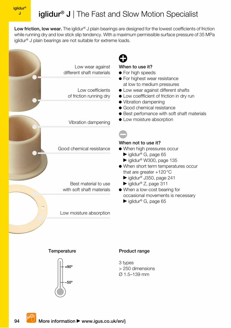
Low friction, low wear. The iglidur® J plain bearings are designed for the lowest coefficients of friction while running dry and low stick slip tendency. With a maximum permissible surface pressure of 35 MPa iglidur® J plain bearings are not suitable for extreme loads.
When to use it? For high speeds
For highest wear resistance at low to medium pressures
Low wear against different shafts Low coeffficient of friction in dry run Vibration dampening Good chemical resistance Best perfomance with soft shaft materials Low moisture absorption
When not to use it? When high pressures occur
iglidur® G, page 65 iglidur® W300, page 135
When short term temperatures occur that are greater +120 °C
iglidur® J350, page 241 iglidur® Z, page 311
When a low-cost bearing for occasional movements is necessary
iglidur® G, page 65
Low wear against different shaft materials
Low coefficients of friction running dry
Good chemical resistance
Best material to use with soft shaft materials
Low moisture absorption
Vibration dampening
Temperature Product range
3 types> 250 dimensionsØ 1.5–139 mm

igus® (UK) Ltd | Phone (01604) 677240 Fax -245 | [email protected] | www.igus.co.uk 95
iglidur® Jiglidur® J | Application Examples
www.igus.co.uk/mountainbike www.igus.co.uk/powderpress
www.igus.co.uk/pullback-star www.igus.co.uk/sawmill
Typical sectors of industry and application areas
Automation Printing industry Beverage technology Aerospace
engineering Cleanroom etc.
Improve technology and reduce costs –
310 exciting examples for iglidur® plain
bearings online
www.igus.co.uk/iglidur-applications
96
iglidur® J
0.001 0.01 0.1 1.0 10.0
100.0
10.0
1.0
0.1
0.01
Lifetime calculation, CAD files and much more support www.igus.co.uk/en/j
iglidur® J | Technical Data
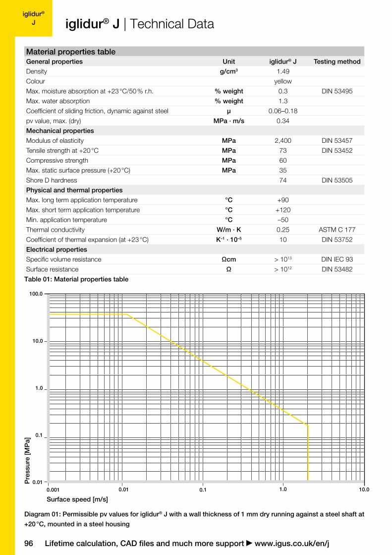
Diagram 01: Permissible pv values for iglidur® J with a wall thickness of 1 mm dry running against a steel shaft at
+20 °C, mounted in a steel housing
Surface speed [m/s]
Material properties table General properties Unit iglidur® J Testing method
Density g/cm3 1.49
Colour yellow
Max. moisture absorption at +23 °C/50 % r.h. % weight 0.3 DIN 53495
Max. water absorption % weight 1.3
Coefficient of sliding friction, dynamic against steel µ 0.06–0.18
pv value, max. (dry) MPa · m/s 0.34
Mechanical properties
Modulus of elasticity MPa 2,400 DIN 53457
Tensile strength at +20 °C MPa 73 DIN 53452
Compressive strength MPa 60
Max. static surface pressure (+20 °C) MPa 35
Shore D hardness 74 DIN 53505
Physical and thermal properties
Max. long term application temperature °C +90
Max. short term application temperature °C +120
Min. application temperature °C –50
Thermal conductivity W/m · K 0.25 ASTM C 177
Coefficient of thermal expansion (at +23 °C) K–1 · 10–5 10 DIN 53752
Electrical properties
Specific volume resistance Ωcm > 1013 DIN IEC 93
Surface resistance Ω > 1012 DIN 53482
Table 01: Material properties table
Pre
ssur
e [M
Pa]
igus® (UK) Ltd | Phone (01604) 677240 Fax -245 | [email protected] | www.igus.co.uk 97
iglidur® J
20 50 80 900
20
40
60
80
120
100
60 704030
0.0
5.0
2.5
7.5
10.0
12.5
0.0 12.5 37.5 50.025.0
iglidur® J | Technical Data
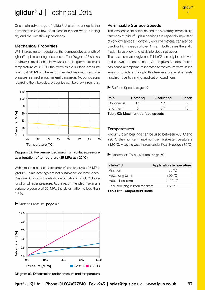
One main advantage of iglidur® J plain bearings is the
combination of a low coefficient of friction when running
dry and the low stickslip tendency.
Mechanical PropertiesWith increasing temperatures, the compressive strength of
iglidur® J plain bearings decreases. The Diagram 02 shows
this inverse relationship. However, at the longterm maximum
temperature of +90 °C the permissible surface pressure
is almost 20 MPa. The recommended maximum surface
pressure is a mechanical material parameter. No conclusions
regarding the tribological properties can be drawn from this.
With a recommended maximum surface pressure of 35 MPa,
iglidur® J plain bearings are not suitable for extreme loads.
Diagram 03 shows the elastic deformation of iglidur® J as a
function of radial pressure. At the recommended maximum
surface pressure of 35 MPa the deformation is less than
2.5 %.
Surface Pressure, page 47
Diagram 02: Recommended maximum surface pressure
as a function of temperature (35 MPa at +20 °C)
Temperature [°C]
Diagram 03: Deformation under pressure and temperature
Permissible Surface SpeedsThe low coefficient of friction and the extremely low stick slip
tendency of iglidur® J plain bearings are especially important
at very low speeds. However, iglidur® J material can also be
used for high speeds of over 1m/s. In both cases the static
friction is very low and stick slip does not occur.
The maximum values given in Table 02 can only be achieved
at the lowest pressure loads. At the given speeds, friction
can cause a temperature increase to maximum permissible
levels. In practice, though, this temperature level is rarely
reached, due to varying application conditions.
Surface Speed, page 49
m/s Rotating Oscillating Linear
Continuous 1.5 1.1 8
Short term 3 2.1 10
Table 02: Maximum surface speeds
Temperaturesiglidur® J plain bearings can be used between –50 °C and
+90 °C; the short-term maximum permissible temperature is
+120 °C. Also, the wear increases significantly above +80 °C.
Application Temperatures, page 50
iglidur® J Application temperature
Minimum –50 °C
Max., long term +90 °C
Max., short term +120 °C
Add. securing is required from +60 °C
Table 03: Temperature limits
Pressure [MPa] +23 °C +60 °C
Pre
ssur
e [M
Pa]
Def
orm
atio
n [%
]

98
iglidur® J
0.1
0.2
0.4
0.3
0.05 0.10 0.15 0.20 0.25 0.30 0.35
1050 15 20 25 30 350.00
0.05
0.10
0.15
0.30
0.20
0.25
Lifetime calculation, CAD files and much more support www.igus.co.uk/en/j
iglidur® J | Technical Data
Diagram 04: Coefficient of friction as a function of the
running speed, p = 0.75 MPa
Surface speed [m/s]
Diagram 05: Coefficient of friction as a function of the
pressure, v = 0.01 m/s
Pressure [MPa]
Shaft Materials
Friction and wear are also dependent, to a large extent,
on the shaft material. With increasing shaft roughness, the
coefficient of friction also increases. The best case is a
ground surface with an average roughness Ra = 0.1–0.3 µm
(Diagram 06).
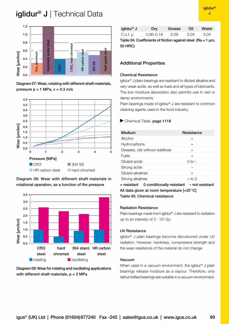
Diagrams 07 to 09 show results of testing different shaft
materials with plain bearings made of iglidur® J.
If iglidur® J plain bearings are used in rotational applications
with pressures under 2 MPa, several shaft materials are sui-
table. A Hard Chromed shaft provides the lowest wear in this
range. When compared to most iglidur® materials, iglidur® J
has very low wear results at low loads compared with all
shaft materials tested. Also, for increasing pressures up to
5 MPa, the wear resistance of iglidur® J is excellent.
In oscillating operation with Cf53 Steel and HR Carbon
Steel, the wear of iglidur® J is slightly higher than for rotati-
on. As Diagram 09 shows, the difference in wear between
rotation and oscillating movements is most significant for
303 stainless steel shafts.
If the shaft material you plan to use is not contained in this
list, please contact us.
Shaft Materials, page 55
Friction and WearSimilar to wear resistance, the coefficient of friction µ also
changes with the load. Diagram 05 shows the coefficients
of friction for different loads. The level of the coefficient of
friction is very good for all loads with iglidur® J.
Coefficients of Friction and Surfaces, page 52
Wear Resistance, page 53
Co
effic
ient
of
fric
tion
[µ]
Co
effic
ient
of
fric
tion
[µ]
0.10
0.15
0.20
0.35
0.40
0.30
0.25
0.1 0.4 0.7 1.0 1.3 1.6
Diagram 06: Coefficient of friction as function of the
shaft surface (Cf53 hardened and ground steel)
Shaft roughness Ra [µm]
Co
effic
ient
of
fric
tion
[µ]
igus® (UK) Ltd | Phone (01604) 677240 Fax -245 | [email protected] | www.igus.co.uk 99
iglidur® Jiglidur® J | Technical Data
Diagram 07: Wear, rotating with different shaft materials,
pressure p = 1 MPa, v = 0.3 m/s
iglidur® J Dry Grease Oil Water
C.o.f. µ 0.06–0.18 0.09 0.04 0.04
Table 04: Coefficients of friction against steel (Ra = 1 µm,
50 HRC)
Additional Properties
Chemical Resistance
iglidur® J plain bearings are resistant to diluted alkaline and
very weak acids, as well as fuels and all types of lubricants.
The low moisture absorption also permits use in wet or
damp environments.
Plain bearings made of iglidur® J are resistant to common
cleaning agents used in the food industry.
Chemical Table, page 1118
Medium Resistance
Alcohol +
Hydrocarbons +
Greases, oils without additives +
Fuels +
Diluted acids 0 to –
Strong acids –
Diluted alkalines +
Strong alkalines + to 0
+ resistant 0 conditionally resistant – not resistant
All data given at room temperature [+20 °C]
Table 05: Chemical resistance
Radiation Resistance
Plain bearings made from iglidur® J are resistant to radiation
up to an intensity of 3 · 102 Gy.
UV Resistance
iglidur® J plain bearings become discoloured under UV
radiation. However, hardness, compressive strength and
the wear resistance of the material do not change.
Vacuum
When used in a vacuum environment, the iglidur® J plain
bearings release moisture as a vapour. Therefore, only
dehumidified bearings are suitable in a vacuum environment.
0.0
0.4
0.6
0.8
0.2
1.0
1.2
Aut
om
atic
scr
ew s
teel
HR
car
bon
ste
el
H.a
. alu
min
um
Cf5
3, h
ard
chr
om
ed
304
SS
Cf5
3
Hig
h g
rad
e st
eel
Wea
r [µ
m/k
m]
0.0
0.5
1.0
3.5
1.5
2.5
2.0
3.0
0.0
2.0
3.0
3.5
4.0
4.5
1.0
2.5
1.5
0.5
0 1 52 3 4
Diagram 08: Wear with different shaft materials in
rotational operation, as a function of the pressure
Pressure [MPa]
Cf53 304 SS
HR carbon steel hard chromed
Wea
r [µ
m/k
m]
Wea
r [µ
m/k
m]
Diagram 09: Wear for rotating and oscillating applications
with different shaft materials, p = 2 MPa
Cf53
steel
hard
chromed
304 stainl.
steel
HR carbon
steel
rotating oscillating
100
iglidur® J
0.00
0.02
0.04
0.06
0.08
0.09
0.10
0.01
0.03
0.05
0.07
0.00 0.16 0.33 0.49 0.65 0.81 0.98 1.14 1.30
Lifetime calculation, CAD files and much more support www.igus.co.uk/en/j
iglidur® J | Technical Data
Electrical Properties
iglidur® J plain bearings are electrically insulating.
Specific volume resistance > 1013 Ωcm
Surface resistance > 1012 Ω 10
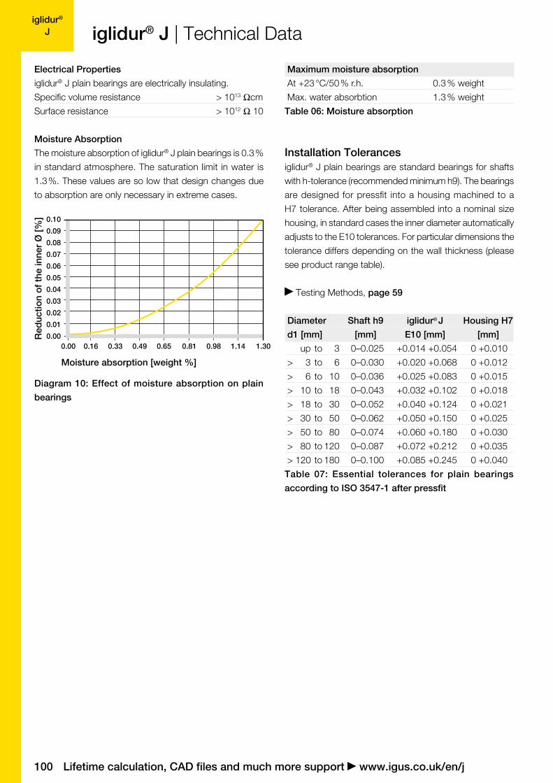
Moisture Absorption
The moisture absorption of iglidur® J plain bearings is 0.3 %
in standard atmosphere. The saturation limit in water is
1.3 %. These values are so low that design changes due
to absorption are only necessary in extreme cases.
Maximum moisture absorption
At +23 °C/50 % r.h. 0.3 % weight
Max. water absorbtion 1.3 % weight
Table 06: Moisture absorption
Installation Tolerancesiglidur® J plain bearings are standard bearings for shafts
with h-tolerance (recommended minimum h9). The bearings
are designed for pressfit into a housing machined to a
H7 tolerance. After being assembled into a nominal size
housing, in standard cases the inner diameter automatically
adjusts to the E10 tolerances. For particular dimensions the
tolerance differs depending on the wall thickness (please
see product range table).
Testing Methods, page 59
Diameter Shaft h9 iglidur® J Housing H7
d1 [mm] [mm] E10 [mm] [mm]
up to 3 0–0.025 +0.014 +0.054 0 +0.010
> 3 to 6 0–0.030 +0.020 +0.068 0 +0.012
> 6 to 10 0–0.036 +0.025 +0.083 0 +0.015
> 10 to 18 0–0.043 +0.032 +0.102 0 +0.018
> 18 to 30 0–0.052 +0.040 +0.124 0 +0.021
> 30 to 50 0–0.062 +0.050 +0.150 0 +0.025
> 50 to 80 0–0.074 +0.060 +0.180 0 +0.030
> 80 to 120 0–0.087 +0.072 +0.212 0 +0.035
> 120 to 180 0–0.100 +0.085 +0.245 0 +0.040
Table 07: Essential tolerances for plain bearings
according to ISO 3547-1 after pressfit
Moisture absorption [weight %]
Diagram 10: Effect of moisture absorption on plain
bearings
Red
uctio
n o
f th
e in
ner
Ø [%
]
igus® (UK) Ltd | Phone (01604) 677240 Fax -245 | [email protected] | www.igus.co.uk 101
iglidur® J
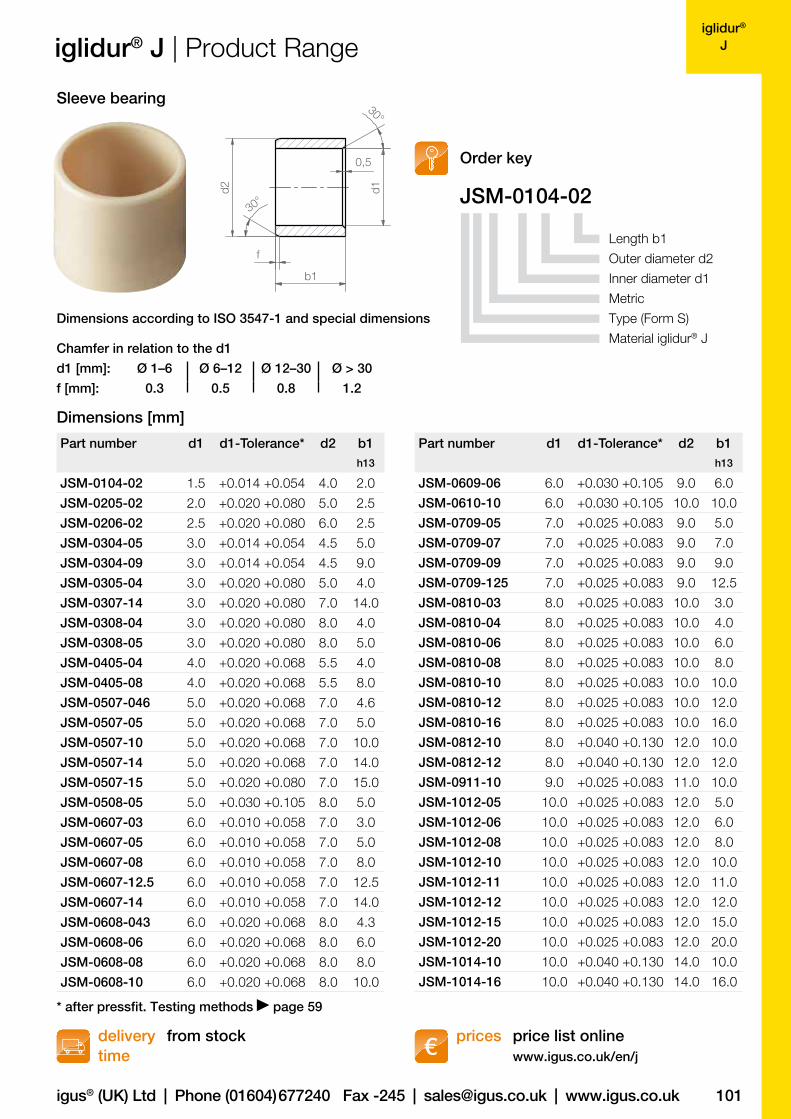
d1 [mm]: Ø 1–6 Ø 6–12 Ø 12–30 Ø > 30
f [mm]: 0.3 0.5 0.8 1.2
JSM-0104-0230°
d1d2
f
b1
30°
0,5
Part number d1 d1-Tolerance* d2 b1h13
JSM-0104-02 1.5 +0.014 +0.054 4.0 2.0
JSM-0205-02 2.0 +0.020 +0.080 5.0 2.5
JSM-0206-02 2.5 +0.020 +0.080 6.0 2.5
JSM-0304-05 3.0 +0.014 +0.054 4.5 5.0
JSM-0304-09 3.0 +0.014 +0.054 4.5 9.0
JSM-0305-04 3.0 +0.020 +0.080 5.0 4.0
JSM-0307-14 3.0 +0.020 +0.080 7.0 14.0
JSM-0308-04 3.0 +0.020 +0.080 8.0 4.0
JSM-0308-05 3.0 +0.020 +0.080 8.0 5.0
JSM-0405-04 4.0 +0.020 +0.068 5.5 4.0
JSM-0405-08 4.0 +0.020 +0.068 5.5 8.0
JSM-0507-046 5.0 +0.020 +0.068 7.0 4.6
JSM-0507-05 5.0 +0.020 +0.068 7.0 5.0
JSM-0507-10 5.0 +0.020 +0.068 7.0 10.0
JSM-0507-14 5.0 +0.020 +0.068 7.0 14.0
JSM-0507-15 5.0 +0.020 +0.080 7.0 15.0
JSM-0508-05 5.0 +0.030 +0.105 8.0 5.0
JSM-0607-03 6.0 +0.010 +0.058 7.0 3.0
JSM-0607-05 6.0 +0.010 +0.058 7.0 5.0
JSM-0607-08 6.0 +0.010 +0.058 7.0 8.0
JSM-0607-12.5 6.0 +0.010 +0.058 7.0 12.5
JSM-0607-14 6.0 +0.010 +0.058 7.0 14.0
JSM-0608-043 6.0 +0.020 +0.068 8.0 4.3
JSM-0608-06 6.0 +0.020 +0.068 8.0 6.0
JSM-0608-08 6.0 +0.020 +0.068 8.0 8.0
JSM-0608-10 6.0 +0.020 +0.068 8.0 10.0
Part number d1 d1-Tolerance* d2 b1h13
JSM-0609-06 6.0 +0.030 +0.105 9.0 6.0
JSM-0610-10 6.0 +0.030 +0.105 10.0 10.0
JSM-0709-05 7.0 +0.025 +0.083 9.0 5.0
JSM-0709-07 7.0 +0.025 +0.083 9.0 7.0
JSM-0709-09 7.0 +0.025 +0.083 9.0 9.0
JSM-0709-125 7.0 +0.025 +0.083 9.0 12.5
JSM-0810-03 8.0 +0.025 +0.083 10.0 3.0
JSM-0810-04 8.0 +0.025 +0.083 10.0 4.0
JSM-0810-06 8.0 +0.025 +0.083 10.0 6.0
JSM-0810-08 8.0 +0.025 +0.083 10.0 8.0
JSM-0810-10 8.0 +0.025 +0.083 10.0 10.0
JSM-0810-12 8.0 +0.025 +0.083 10.0 12.0
JSM-0810-16 8.0 +0.025 +0.083 10.0 16.0
JSM-0812-10 8.0 +0.040 +0.130 12.0 10.0
JSM-0812-12 8.0 +0.040 +0.130 12.0 12.0
JSM-0911-10 9.0 +0.025 +0.083 11.0 10.0
JSM-1012-05 10.0 +0.025 +0.083 12.0 5.0
JSM-1012-06 10.0 +0.025 +0.083 12.0 6.0
JSM-1012-08 10.0 +0.025 +0.083 12.0 8.0
JSM-1012-10 10.0 +0.025 +0.083 12.0 10.0
JSM-1012-11 10.0 +0.025 +0.083 12.0 11.0
JSM-1012-12 10.0 +0.025 +0.083 12.0 12.0
JSM-1012-15 10.0 +0.025 +0.083 12.0 15.0
JSM-1012-20 10.0 +0.025 +0.083 12.0 20.0
JSM-1014-10 10.0 +0.040 +0.130 14.0 10.0
JSM-1014-16 10.0 +0.040 +0.130 14.0 16.0
iglidur® J | Product Range
price list onlinewww.igus.co.uk/en/j
delivery time
prices from stock
Sleeve bearing
Order key
Length b1
Outer diameter d2
Inner diameter d1
Metric
Type (Form S)
Material iglidur® J
Dimensions according to ISO 3547-1 and special dimensions
Chamfer in relation to the d1
Dimensions [mm]
* after pressfit. Testing methods page 59
102
iglidur® J
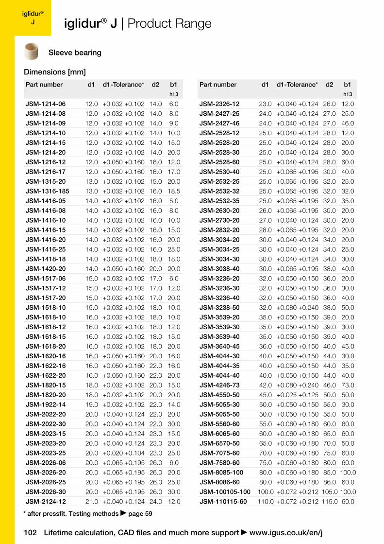
Part number d1 d1-Tolerance* d2 b1h13
JSM-1214-06 12.0 +0.032 +0.102 14.0 6.0
JSM-1214-08 12.0 +0.032 +0.102 14.0 8.0
JSM-1214-09 12.0 +0.032 +0.102 14.0 9.0
JSM-1214-10 12.0 +0.032 +0.102 14.0 10.0
JSM-1214-15 12.0 +0.032 +0.102 14.0 15.0
JSM-1214-20 12.0 +0.032 +0.102 14.0 20.0
JSM-1216-12 12.0 +0.050 +0.160 16.0 12.0
JSM-1216-17 12.0 +0.050 +0.160 16.0 17.0
JSM-1315-20 13.0 +0.032 +0.102 15.0 20.0
JSM-1316-185 13.0 +0.032 +0.102 16.0 18.5
JSM-1416-05 14.0 +0.032 +0.102 16.0 5.0
JSM-1416-08 14.0 +0.032 +0.102 16.0 8.0
JSM-1416-10 14.0 +0.032 +0.102 16.0 10.0
JSM-1416-15 14.0 +0.032 +0.102 16.0 15.0
JSM-1416-20 14.0 +0.032 +0.102 16.0 20.0
JSM-1416-25 14.0 +0.032 +0.102 16.0 25.0
JSM-1418-18 14.0 +0.032 +0.102 18.0 18.0
JSM-1420-20 14.0 +0.050 +0.160 20.0 20.0
JSM-1517-06 15.0 +0.032 +0.102 17.0 6.0
JSM-1517-12 15.0 +0.032 +0.102 17.0 12.0
JSM-1517-20 15.0 +0.032 +0.102 17.0 20.0
JSM-1518-10 15.0 +0.032 +0.102 18.0 10.0
JSM-1618-10 16.0 +0.032 +0.102 18.0 10.0
JSM-1618-12 16.0 +0.032 +0.102 18.0 12.0
JSM-1618-15 16.0 +0.032 +0.102 18.0 15.0
JSM-1618-20 16.0 +0.032 +0.102 18.0 20.0
JSM-1620-16 16.0 +0.050 +0.160 20.0 16.0
JSM-1622-16 16.0 +0.050 +0.160 22.0 16.0
JSM-1622-20 16.0 +0.050 +0.160 22.0 20.0
JSM-1820-15 18.0 +0.032 +0.102 20.0 15.0
JSM-1820-20 18.0 +0.032 +0.102 20.0 20.0
JSM-1922-14 19.0 +0.032 +0.102 22.0 14.0
JSM-2022-20 20.0 +0.040 +0.124 22.0 20.0
JSM-2022-30 20.0 +0.040 +0.124 22.0 30.0
JSM-2023-15 20.0 +0.040 +0.124 23.0 15.0
JSM-2023-20 20.0 +0.040 +0.124 23.0 20.0
JSM-2023-25 20.0 +0.020 +0.104 23.0 25.0
JSM-2026-06 20.0 +0.065 +0.195 26.0 6.0
JSM-2026-20 20.0 +0.065 +0.195 26.0 20.0
JSM-2026-25 20.0 +0.065 +0.195 26.0 25.0
JSM-2026-30 20.0 +0.065 +0.195 26.0 30.0
JSM-2124-12 21.0 +0.040 +0.124 24.0 12.0
Part number d1 d1-Tolerance* d2 b1h13
JSM-2326-12 23.0 +0.040 +0.124 26.0 12.0
JSM-2427-25 24.0 +0.040 +0.124 27.0 25.0
JSM-2427-46 24.0 +0.040 +0.124 27.0 46.0
JSM-2528-12 25.0 +0.040 +0.124 28.0 12.0
JSM-2528-20 25.0 +0.040 +0.124 28.0 20.0
JSM-2528-30 25.0 +0.040 +0.124 28.0 30.0
JSM-2528-60 25.0 +0.040 +0.124 28.0 60.0
JSM-2530-40 25.0 +0.065 +0.195 30.0 40.0
JSM-2532-25 25.0 +0.065 +0.195 32.0 25.0
JSM-2532-32 25.0 +0.065 +0.195 32.0 32.0
JSM-2532-35 25.0 +0.065 +0.195 32.0 35.0
JSM-2630-20 26.0 +0.065 +0.195 30.0 20.0
JSM-2730-20 27.0 +0.040 +0.124 30.0 20.0
JSM-2832-20 28.0 +0.065 +0.195 32.0 20.0
JSM-3034-20 30.0 +0.040 +0.124 34.0 20.0
JSM-3034-25 30.0 +0.040 +0.124 34.0 25.0
JSM-3034-30 30.0 +0.040 +0.124 34.0 30.0
JSM-3038-40 30.0 +0.065 +0.195 38.0 40.0
JSM-3236-20 32.0 +0.050 +0.150 36.0 20.0
JSM-3236-30 32.0 +0.050 +0.150 36.0 30.0
JSM-3236-40 32.0 +0.050 +0.150 36.0 40.0
JSM-3238-50 32.0 +0.080 +0.240 38.0 50.0
JSM-3539-20 35.0 +0.050 +0.150 39.0 20.0
JSM-3539-30 35.0 +0.050 +0.150 39.0 30.0
JSM-3539-40 35.0 +0.050 +0.150 39.0 40.0
JSM-3640-45 36.0 +0.050 +0.150 40.0 45.0
JSM-4044-30 40.0 +0.050 +0.150 44.0 30.0
JSM-4044-35 40.0 +0.050 +0.150 44.0 35.0
JSM-4044-40 40.0 +0.050 +0.150 44.0 40.0
JSM-4246-73 42.0 +0.080 +0.240 46.0 73.0
JSM-4550-50 45.0 +0.025 +0.125 50.0 50.0
JSM-5055-30 50.0 +0.050 +0.150 55.0 30.0
JSM-5055-50 50.0 +0.050 +0.150 55.0 50.0
JSM-5560-60 55.0 +0.060 +0.180 60.0 60.0
JSM-6065-60 60.0 +0.060 +0.180 65.0 60.0
JSM-6570-50 65.0 +0.060 +0.180 70.0 50.0
JSM-7075-60 70.0 +0.060 +0.180 75.0 60.0
JSM-7580-60 75.0 +0.060 +0.180 80.0 60.0
JSM-8085-100 80.0 +0.060 +0.180 85.0 100.0
JSM-8086-60 80.0 +0.060 +0.180 86.0 60.0
JSM-100105-100 100.0 +0.072 +0.212 105.0 100.0
JSM-110115-60 110.0 +0.072 +0.212 115.0 60.0
Lifetime calculation, CAD files and much more support www.igus.co.uk/en/j
iglidur® J | Product Range
Sleeve bearing
Dimensions [mm]
* after pressfit. Testing methods page 59
igus® (UK) Ltd | Phone (01604) 677240 Fax -245 | [email protected] | www.igus.co.uk 103
iglidur® J
d1 [mm]: Ø 1–6 Ø 6–12 Ø 12–30 Ø > 30
f [mm]: 0.3 0.5 0.8 1.2
d230°
f
b1
b2d1 d3
r
r = max.
0.5 mm
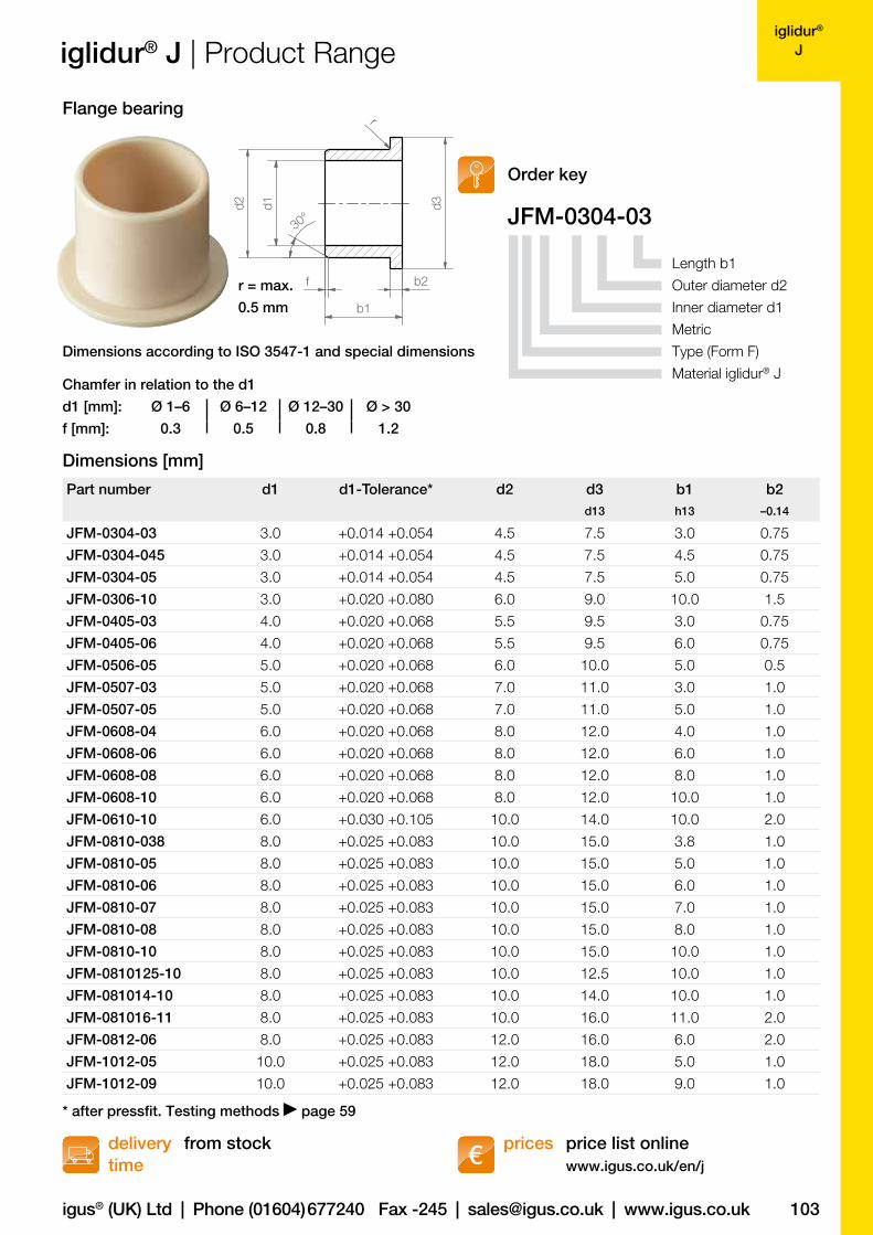
JFM-0304-03
Part number d1 d1-Tolerance* d2 d3 b1 b2d13 h13 –0.14
JFM-0304-03 3.0 +0.014 +0.054 4.5 7.5 3.0 0.75
JFM-0304-045 3.0 +0.014 +0.054 4.5 7.5 4.5 0.75
JFM-0304-05 3.0 +0.014 +0.054 4.5 7.5 5.0 0.75
JFM-0306-10 3.0 +0.020 +0.080 6.0 9.0 10.0 1.5
JFM-0405-03 4.0 +0.020 +0.068 5.5 9.5 3.0 0.75
JFM-0405-06 4.0 +0.020 +0.068 5.5 9.5 6.0 0.75
JFM-0506-05 5.0 +0.020 +0.068 6.0 10.0 5.0 0.5
JFM-0507-03 5.0 +0.020 +0.068 7.0 11.0 3.0 1.0
JFM-0507-05 5.0 +0.020 +0.068 7.0 11.0 5.0 1.0
JFM-0608-04 6.0 +0.020 +0.068 8.0 12.0 4.0 1.0
JFM-0608-06 6.0 +0.020 +0.068 8.0 12.0 6.0 1.0
JFM-0608-08 6.0 +0.020 +0.068 8.0 12.0 8.0 1.0
JFM-0608-10 6.0 +0.020 +0.068 8.0 12.0 10.0 1.0
JFM-0610-10 6.0 +0.030 +0.105 10.0 14.0 10.0 2.0
JFM-0810-038 8.0 +0.025 +0.083 10.0 15.0 3.8 1.0
JFM-0810-05 8.0 +0.025 +0.083 10.0 15.0 5.0 1.0
JFM-0810-06 8.0 +0.025 +0.083 10.0 15.0 6.0 1.0
JFM-0810-07 8.0 +0.025 +0.083 10.0 15.0 7.0 1.0
JFM-0810-08 8.0 +0.025 +0.083 10.0 15.0 8.0 1.0
JFM-0810-10 8.0 +0.025 +0.083 10.0 15.0 10.0 1.0
JFM-0810125-10 8.0 +0.025 +0.083 10.0 12.5 10.0 1.0
JFM-081014-10 8.0 +0.025 +0.083 10.0 14.0 10.0 1.0
JFM-081016-11 8.0 +0.025 +0.083 10.0 16.0 11.0 2.0
JFM-0812-06 8.0 +0.025 +0.083 12.0 16.0 6.0 2.0
JFM-1012-05 10.0 +0.025 +0.083 12.0 18.0 5.0 1.0
JFM-1012-09 10.0 +0.025 +0.083 12.0 18.0 9.0 1.0
iglidur® J | Product Range
price list onlinewww.igus.co.uk/en/j
delivery time
prices from stock
Flange bearing
Order key
Length b1
Outer diameter d2
Inner diameter d1
Metric
Type (Form F)
Material iglidur® J
Dimensions according to ISO 3547-1 and special dimensions
Chamfer in relation to the d1
Dimensions [mm]
* after pressfit. Testing methods page 59
104
iglidur® J
Part number d1 d1-Tolerance* d2 d3 b1 b2d13 h13 –0.14
JFM-1012-10 10.0 +0.025 +0.083 12.0 18.0 10.0 1.0
JFM-1012-12 10.0 +0.025 +0.083 12.0 18.0 12.0 1.0
JFM-1012-15 10.0 +0.025 +0.083 12.0 18.0 15.0 1.0
JFM-1012-18 10.0 +0.025 +0.083 12.0 18.0 18.0 1.0
JFM-101215-035 10.0 +0.025 +0.083 12.0 15.0 3.5 1.0
JFM-1014-14 10.0 +0.025 +0.083 14.0 17.5 14.0 1.0
JFM-1113-05 11.0 +0.032 +0.102 13.0 18.0 5.0 1.0
JFM-1214-05 12.0 +0.032 +0.102 14.0 20.0 5.0 1.0
JFM-1214-07 12.0 +0.032 +0.102 14.0 20.0 7.0 1.0
JFM-1214-09 12.0 +0.032 +0.102 14.0 20.0 9.0 1.0
JFM-1214-12 12.0 +0.032 +0.102 14.0 20.0 12.0 1.0
JFM-1214-15 12.0 +0.032 +0.102 14.0 20.0 15.0 1.0
JFM-121418-045 12.0 +0.032 +0.102 14.0 18.0 4.5 1.0
JFM-121418-10 12.0 +0.032 +0.102 14.0 18.0 10.0 1.0
JFM-1218-08 12.0 +0.050 +0.160 18.0 24.0 8.0 3.0
JFM-1218-12 12.0 +0.050 +0.160 18.0 24.0 12.0 3.0
JFM-1218-20 12.0 +0.050 +0.160 18.0 22.0 20.0 3.0
JFM-1416-03 14.0 +0.032 +0.102 16.0 22.0 3.0 1.0
JFM-1416-10 14.0 +0.032 +0.102 16.0 22.0 10.0 1.0
JFM-1416-12 14.0 +0.032 +0.102 16.0 22.0 12.0 1.0
JFM-1416-17 14.0 +0.032 +0.102 16.0 22.0 17.0 1.0
JFM-141822-20 14.0 +0.032 +0.102 18.0 22.0 20.0 2.0
JFM-141825-24 14.0 +0.032 +0.102 18.0 25.0 24.0 2.0
JFM-1517-04 15.0 +0.032 +0.102 17.0 23.0 4.0 1.0
JFM-1517-055 15.0 +0.032 +0.102 17.0 23.0 5.5 1.0
JFM-1517-09 15.0 +0.032 +0.102 17.0 23.0 9.0 1.0
JFM-1517-12 15.0 +0.032 +0.102 17.0 23.0 12.0 1.0
JFM-1517-17 15.0 +0.032 +0.102 17.0 23.0 17.0 1.0
JFM-1521-20 15.0 +0.050 +0.160 21.0 27.0 20.0 3.0
JFM-1618-06 16.0 +0.032 +0.102 18.0 24.0 6.0 1.0
JFM-1618-16 16.0 +0.032 +0.102 18.0 24.0 16.0 1.0
JFM-1618-17 16.0 +0.032 +0.102 18.0 24.0 17.0 1.0
JFM-1622-12 16.0 +0.050 +0.160 22.0 28.0 12.0 3.0
JFM-1622-15 16.0 +0.050 +0.160 22.0 28.0 15.0 3.0
JFM-1719-09 17.0 +0.032 +0.102 19.0 25.0 9.0 1.0
JFM-1719-21 17.0 +0.032 +0.102 19.0 25.0 21.0 1.0
JFM-1820-04 18.0 +0.032 +0.102 20.0 26.0 4.0 1.0
JFM-1820-12 18.0 +0.032 +0.102 20.0 26.0 12.0 1.0
JFM-1820-22 18.0 +0.032 +0.102 20.0 26.0 22.0 1.0
JFM-1922-36 19.0 +0.032 +0.102 22.0 26.0 36.0 1.0
JFM-2023-11 20.0 +0.040 +0.124 23.0 30.0 11.5 1.5
JFM-2023-15.5 20.0 +0.040 +0.124 23.0 30.0 15.5 1.5
JFM-2023-21 20.0 +0.040 +0.124 23.0 30.0 21.5 1.5
Lifetime calculation, CAD files and much more support www.igus.co.uk/en/j
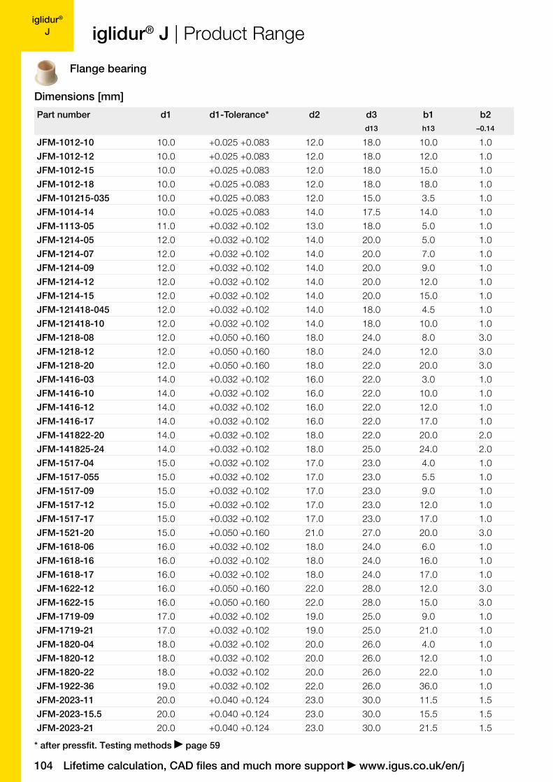
iglidur® J | Product Range
Dimensions [mm]
Flange bearing
* after pressfit. Testing methods page 59

igus® (UK) Ltd | Phone (01604) 677240 Fax -245 | [email protected] | www.igus.co.uk 105
iglidur® J
Part number d1 d1-Tolerance* d2 d3 b1 b2d13 h13 –0.14
JFM-202530-15 20.0 +0.065 +0.195 25.0 30.0 15.0 2.0
JFM-2026-15 20.0 +0.065 +0.195 26.0 32.0 15.0 3.0
JFM-2026-20 20.0 +0.065 +0.195 26.0 32.0 20.0 3.0
JFM-2026-25 20.0 +0.065 +0.195 26.0 32.0 25.0 3.0
JFM-222532-08 22.0 +0.040 +0.124 25.0 32.0 8.0 1.5
JFM-2430-30 24.0 +0.040 +0.124 30.0 36.0 30.0 3.0
JFM-2528-06 25.0 +0.040 +0.124 28.0 35.0 6.0 1.5
JFM-2528-12 25.0 +0.040 +0.124 28.0 35.0 12.0 1.5
JFM-2528-14.5 25.0 +0.040 +0.124 28.0 35.0 14.5 1.5
JFM-2528-21 25.0 +0.040 +0.124 28.0 35.0 21.5 1.5
JFM-252839-05 25.0 +0.040 +0.124 28.0 39.0 5.0 1.5
JFM-252839-075 25.0 +0.040 +0.124 28.0 39.0 7.5 1.5
JFM-2532-20 25.0 +0.065 +0.195 32.0 38.0 20.0 4.0
JFM-2532-25 25.0 +0.065 +0.195 32.0 38.0 25.0 4.0
JFM-283235-07 28.0 +0.065 +0.195 32.0 35.0 7.0 2.0
JFM-283239-20 28.0 +0.040 +0.124 32.0 39.0 20.0 2.0
JFM-303240-12 30.0 +0.040 +0.124 32.0 40.0 12.0 1.0
JFM-3034-20 30.0 +0.040 +0.124 34.0 42.0 20.0 2.0
JFM-3034-26 30.0 +0.040 +0.124 34.0 42.0 26.0 2.0
JFM-3038-20 30.0 +0.080 +0.240 38.0 44.0 20.0 4.0
JFM-3038-30 30.0 +0.065 +0.195 38.0 44.0 30.0 4.0
JFM-3038-36 30.0 +0.065 +0.195 38.0 44.0 36.0 4.0
JFM-3539-12 35.0 +0.050 +0.150 39.0 47.0 12.0 2.0
JFM-3539-16 35.0 +0.050 +0.150 39.0 47.0 16.0 2.0
JFM-3539-26 35.0 +0.050 +0.150 39.0 47.0 26.0 2.0
JFM-4044-20 40.0 +0.050 +0.150 44.0 52.0 20.0 2.0
JFM-4044-30 40.0 +0.050 +0.150 44.0 52.0 30.0 2.0
JFM-4044-40 40.0 +0.050 +0.150 44.0 52.0 40.0 2.0
JFM-4550-12 45.0 +0.050 +0.150 50.0 58.0 12.0 2.0
JFM-4550-20 45.0 +0.050 +0.150 50.0 58.0 20.0 2.0
JFM-4550-50 45.0 +0.050 +0.150 50.0 58.0 50.0 2.0
JFM-5055-50 50.0 +0.050 +0.150 55.0 63.0 50.0 2.0
JFM-5055-115 50.0 +0.050 +0.150 55.0 63.0 11.5 2.0
JFM-5560-50 55.0 +0.060 +0.180 60.0 68.0 50.0 2.0
JFM-6065-37 60.0 +0.060 +0.180 65.0 73.0 37.0 2.0
JFM-6065-50 60.0 +0.060 +0.180 65.0 73.0 50.0 2.0
JFM-6570-60 65.0 +0.060 +0.180 70.0 78.0 60.0 2.0
JFM-7075-50 70.0 +0.060 +0.180 75.0 83.0 50.0 2.0
JFM-9095-100 90.0 +0.072 +0.212 95.0 103.0 100.0 2.5
JFM-100105-100 100.0 +0.072 +0.212 105.0 113.0 100.0 2.5
JFM-110115-100 110.0 +0.072 +0.212 115.0 123.0 100.0 2.5
JFM-120125-100 120.0 +0.072 +0.212 125.0 133.0 100.0 2.5
iglidur® J | Product Range
price list onlinewww.igus.co.uk/en/j
delivery time
prices from stock
Dimensions [mm]
* after pressfit. Testing methods page 59
106
iglidur® J
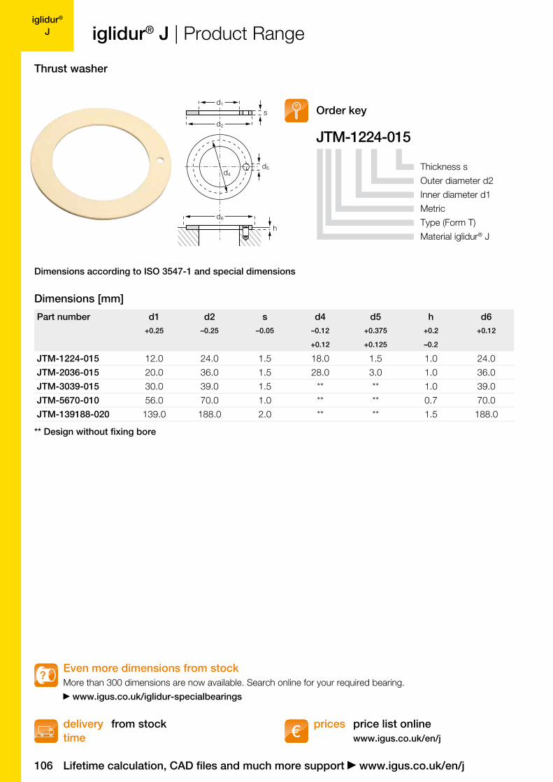
JTM-1224-015
d5
d1
d2
d4
d6
h
s
Part number d1 d2 s d4 d5 h d6+0.25 –0.25 –0.05 –0.12 +0.375 +0.2 +0.12
+0.12 +0.125 –0.2
JTM-1224-015 12.0 24.0 1.5 18.0 1.5 1.0 24.0
JTM-2036-015 20.0 36.0 1.5 28.0 3.0 1.0 36.0
JTM-3039-015 30.0 39.0 1.5 ** ** 1.0 39.0
JTM-5670-010 56.0 70.0 1.0 ** ** 0.7 70.0
JTM-139188-020 139.0 188.0 2.0 ** ** 1.5 188.0
Lifetime calculation, CAD files and much more support www.igus.co.uk/en/j
iglidur® J | Product Range
price list onlinewww.igus.co.uk/en/j
delivery time
prices from stock
Order key
Thickness s
Outer diameter d2
Inner diameter d1
Metric
Type (Form T)
Material iglidur® J
Dimensions according to ISO 3547-1 and special dimensions
Dimensions [mm]
Thrust washer
** Design without fixing bore
Even more dimensions from stock More than 300 dimensions are now available. Search online for your required bearing.
www.igus.co.uk/iglidur-specialbearings
?
igus® (UK) Ltd | Phone (01604) 677240 Fax -245 | [email protected] | www.igus.co.uk 107
iglidur® J
30°
d1d2
f
b1
30°
0,5
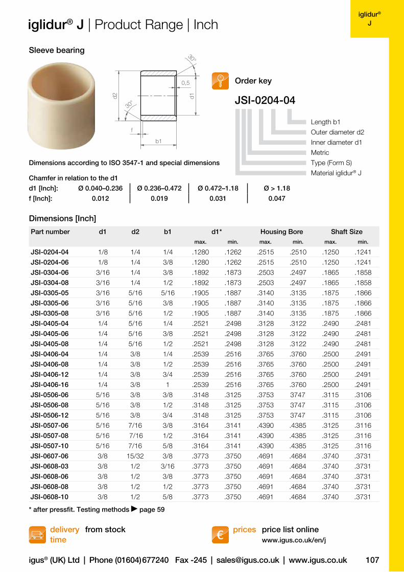
JSI-0204-04
Part number d1 d2 b1 d1* Housing Bore Shaft Sizemax. min. max. min. max. min.
JSI-0204-04 1/8 1/4 1/4 .1280 .1262 .2515 .2510 .1250 .1241
JSI-0204-06 1/8 1/4 3/8 .1280 .1262 .2515 .2510 .1250 .1241
JSI-0304-06 3/16 1/4 3/8 .1892 .1873 .2503 .2497 .1865 .1858
JSI-0304-08 3/16 1/4 1/2 .1892 .1873 .2503 .2497 .1865 .1858
JSI-0305-05 3/16 5/16 5/16 .1905 .1887 .3140 .3135 .1875 .1866
JSI-0305-06 3/16 5/16 3/8 .1905 .1887 .3140 .3135 .1875 .1866
JSI-0305-08 3/16 5/16 1/2 .1905 .1887 .3140 .3135 .1875 .1866
JSI-0405-04 1/4 5/16 1/4 .2521 .2498 .3128 .3122 .2490 .2481
JSI-0405-06 1/4 5/16 3/8 .2521 .2498 .3128 .3122 .2490 .2481
JSI-0405-08 1/4 5/16 1/2 .2521 .2498 .3128 .3122 .2490 .2481
JSI-0406-04 1/4 3/8 1/4 .2539 .2516 .3765 .3760 .2500 .2491
JSI-0406-08 1/4 3/8 1/2 .2539 .2516 .3765 .3760 .2500 .2491
JSI-0406-12 1/4 3/8 3/4 .2539 .2516 .3765 .3760 .2500 .2491
JSI-0406-16 1/4 3/8 1 .2539 .2516 .3765 .3760 .2500 .2491
JSI-0506-06 5/16 3/8 3/8 .3148 .3125 .3753 3747 .3115 .3106
JSI-0506-08 5/16 3/8 1/2 .3148 .3125 .3753 3747 .3115 .3106
JSI-0506-12 5/16 3/8 3/4 .3148 .3125 .3753 3747 .3115 .3106
JSI-0507-06 5/16 7/16 3/8 .3164 .3141 .4390 .4385 .3125 .3116
JSI-0507-08 5/16 7/16 1/2 .3164 .3141 .4390 .4385 .3125 .3116
JSI-0507-10 5/16 7/16 5/8 .3164 .3141 .4390 .4385 .3125 .3116
JSI-0607-06 3/8 15/32 3/8 .3773 .3750 .4691 .4684 .3740 .3731
JSI-0608-03 3/8 1/2 3/16 .3773 .3750 .4691 .4684 .3740 .3731
JSI-0608-06 3/8 1/2 3/8 .3773 .3750 .4691 .4684 .3740 .3731
JSI-0608-08 3/8 1/2 1/2 .3773 .3750 .4691 .4684 .3740 .3731
JSI-0608-10 3/8 1/2 5/8 .3773 .3750 .4691 .4684 .3740 .3731
d1 [Inch]: Ø 0.040–0.236 Ø 0.236–0.472 Ø 0.472–1.18 Ø > 1.18
f [Inch]: 0.012 0.019 0.031 0.047
price list onlinewww.igus.co.uk/en/j
delivery time
prices from stock
Order key
iglidur® J | Product Range | Inch
Dimensions [Inch]
Dimensions according to ISO 3547-1 and special dimensions
Chamfer in relation to the d1
Length b1
Outer diameter d2
Inner diameter d1
Metric
Type (Form S)
Material iglidur® J
Sleeve bearing
* after pressfit. Testing methods page 59
108
iglidur® J
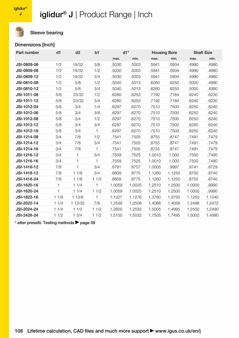
Part number d1 d2 b1 d1* Housing Bore Shaft Sizemax. min. max. min. max. min.
JSI-0809-06 1/2 19/32 3/8 .5030 .5003 .5941 .5934 .4990 .4980
JSI-0809-08 1/2 19/32 1/2 .5030 .5003 .5941 .5934 .4990 .4980
JSI-0809-12 1/2 19/32 3/4 .5030 .5003 .5941 .5934 .4990 .4980
JSI-0810-08 1/2 5/8 1/2 .5040 .5013 .6260 .6250 .5000 .4990
JSI-0810-12 1/2 5/8 3/4 .5040 .5013 .6260 .6250 .5000 .4990
JSI-1011-08 5/8 23/32 1/2 .6280 .6253 .7192 .7184 .6240 .6230
JSI-1011-12 5/8 23/32 3/4 .6280 .6253 .7192 .7184 .6240 .6230
JSI-1012-04 5/8 3/4 1/4 .6297 .6270 .7510 .7500 .6250 .6240
JSI-1012-06 5/8 3/4 3/8 .6297 .6270 .7510 .7500 .6250 .6240
JSI-1012-08 5/8 3/4 1/2 .6297 .6270 .7510 .7500 .6250 .6240
JSI-1012-12 5/8 3/4 3/4 .6297 .6270 .7510 .7500 .6250 .6240
JSI-1012-16 5/8 3/4 1 .6297 .6270 .7510 .7500 .6250 .6240
JSI-1214-08 3/4 7/8 1/2 .7541 .7505 .8755 .8747 .7491 .7479
JSI-1214-12 3/4 7/8 3/4 .7541 .7505 .8755 .8747 .7491 .7479
JSI-1214-16 3/4 7/8 1 .7541 .7505 .8755 .8747 .7491 .7479
JSI-1216-12 3/4 1 3/4 .7559 .7525 1.0010 1.000 .7500 .7490
JSI-1216-16 3/4 1 1 .7559 .7525 1.0010 1.000 .7500 .7490
JSI-1416-12 7/8 1 3/4 .8791 .8757 1.0005 .9997 .8741 .8729
JSI-1418-12 7/8 1 1/8 3/4 .8809 .8775 1.1260 1.1250 .8750 .8740
JSI-1418-24 7/8 1 1/8 1 1/2 .8809 .8775 1.1260 1.1250 .8750 .8740
JSI-1620-16 1 1 1/4 1 1.0059 1.0025 1.2510 1.2500 1.0000 .9990
JSI-1620-24 1 1 1/4 1 1/2 1.0059 1.0025 1.2510 1.2500 1.0000 .9990
JSI-1822-16 1 1/8 1 13/8 1 1.1327 1.1276 1.3760 1.3750 1.1250 1.1240
JSI-2022-14 1 1/4 1 13/32 7/8 1.2548 1.2508 1.4068 1.4058 1.2488 1.2472
JSI-2024-24 1 1/4 1 1/2 1 1/2 1.2600 1.2532 1.5005 1.4995 1.2500 1.2490
JSI-2428-24 1 1/2 1 3/4 1 1/2 1.5100 1.5032 1.7505 1.7495 1.5000 1.4990
Lifetime calculation, CAD files and much more support www.igus.co.uk/en/j
Dimensions [Inch]
iglidur® J | Product Range | Inch
Sleeve bearing
* after pressfit. Testing methods page 59
igus® (UK) Ltd | Phone (01604) 677240 Fax -245 | [email protected] | www.igus.co.uk 109
iglidur® J
d230°
f
b1
b2d1 d3
r
r = max.
0.5 mm
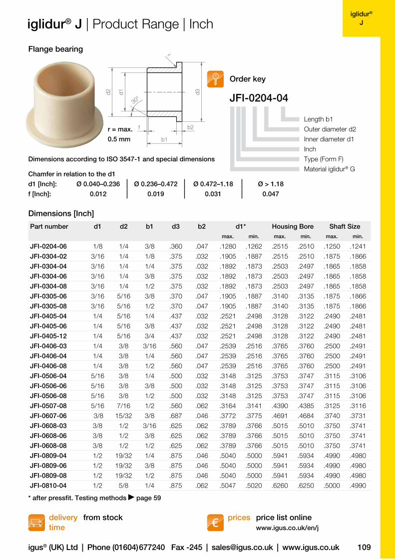
JFI-0204-04
Part number d1 d2 b1 d3 b2 d1* Housing Bore Shaft Sizemax. min. max. min. max. min.
JFI-0204-06 1/8 1/4 3/8 .360 .047 .1280 .1262 .2515 .2510 .1250 .1241
JFI-0304-02 3/16 1/4 1/8 .375 .032 .1905 .1887 .2515 .2510 .1875 .1866
JFI-0304-04 3/16 1/4 1/4 .375 .032 .1892 .1873 .2503 .2497 .1865 .1858
JFI-0304-06 3/16 1/4 3/8 .375 .032 .1892 .1873 .2503 .2497 .1865 .1858
JFI-0304-08 3/16 1/4 1/2 .375 .032 .1892 .1873 .2503 .2497 .1865 .1858
JFI-0305-06 3/16 5/16 3/8 .370 .047 .1905 .1887 .3140 .3135 .1875 .1866
JFI-0305-08 3/16 5/16 1/2 .370 .047 .1905 .1887 .3140 .3135 .1875 .1866
JFI-0405-04 1/4 5/16 1/4 .437 .032 .2521 .2498 .3128 .3122 .2490 .2481
JFI-0405-06 1/4 5/16 3/8 .437 .032 .2521 .2498 .3128 .3122 .2490 .2481
JFI-0405-12 1/4 5/16 3/4 .437 .032 .2521 .2498 .3128 .3122 .2490 .2481
JFI-0406-03 1/4 3/8 3/16 .560 .047 .2539 .2516 .3765 .3760 .2500 .2491
JFI-0406-04 1/4 3/8 1/4 .560 .047 .2539 .2516 .3765 .3760 .2500 .2491
JFI-0406-08 1/4 3/8 1/2 .560 .047 .2539 .2516 .3765 .3760 .2500 .2491
JFI-0506-04 5/16 3/8 1/4 .500 .032 .3148 .3125 .3753 .3747 .3115 .3106
JFI-0506-06 5/16 3/8 3/8 .500 .032 .3148 .3125 .3753 .3747 .3115 .3106
JFI-0506-08 5/16 3/8 1/2 .500 .032 .3148 .3125 .3753 .3747 .3115 .3106
JFI-0507-08 5/16 7/16 1/2 .560 .062 .3164 .3141 .4390 .4385 .3125 .3116
JFI-0607-06 3/8 15/32 3/8 .687 .046 .3772 .3775 .4691 .4684 .3740 .3731
JFI-0608-03 3/8 1/2 3/16 .625 .062 .3789 .3766 .5015 .5010 .3750 .3741
JFI-0608-06 3/8 1/2 3/8 .625 .062 .3789 .3766 .5015 .5010 .3750 .3741
JFI-0608-08 3/8 1/2 1/2 .625 .062 .3789 .3766 .5015 .5010 .3750 .3741
JFI-0809-04 1/2 19/32 1/4 .875 .046 .5040 .5000 .5941 .5934 .4990 .4980
JFI-0809-06 1/2 19/32 3/8 .875 .046 .5040 .5000 .5941 .5934 .4990 .4980
JFI-0809-08 1/2 19/32 1/2 .875 .046 .5040 .5000 .5941 .5934 .4990 .4980
JFI-0810-04 1/2 5/8 1/4 .875 .062 .5047 .5020 .6260 .6250 .5000 .4990
d1 [Inch]: Ø 0.040–0.236 Ø 0.236–0.472 Ø 0.472–1.18 Ø > 1.18
f [Inch]: 0.012 0.019 0.031 0.047
price list onlinewww.igus.co.uk/en/j
delivery time
prices from stock
Order key
Dimensions [Inch]
iglidur® J | Product Range | Inch
Length b1
Outer diameter d2
Inner diameter d1
Inch
Type (Form F)
Material iglidur® G
Flange bearing
Dimensions according to ISO 3547-1 and special dimensions
Chamfer in relation to the d1
* after pressfit. Testing methods page 59
110
iglidur® J
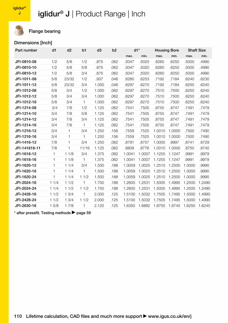
Part number d1 d2 b1 d3 b2 d1* Housing Bore Shaft Sizemax. min. max. min. max. min.
JFI-0810-08 1/2 5/8 1/2 .875 .062 .5047 .5020 .6260 .6250 .5000 .4990
JFI-0810-10 1/2 5/8 5/8 .875 .062 .5047 .5020 .6260 .6250 .5000 .4990
JFI-0810-12 1/2 5/8 3/4 .875 .062 .5047 .5020 .6260 .6250 .5000 .4990
JFI-1011-08 5/8 23/32 1/2 .937 .046 .6280 .6253 .7192 .7184 .6240 .6230
JFI-1011-12 5/8 23/32 3/4 1.000 .046 .6297 .6270 .7192 .7184 .6250 .6240
JFI-1012-08 5/8 3/4 1/2 1.000 .062 .6297 .6270 .7510 .7500 .6250 .6240
JFI-1012-12 5/8 3/4 3/4 1.000 .062 .6297 .6270 .7510 .7500 .6250 .6240
JFI-1012-16 5/8 3/4 1 1.000 .062 .6297 .6270 .7510 .7500 .6250 .6240
JFI-1214-08 3/4 7/8 1/2 1.125 .062 .7541 .7505 .8755 .8747 .7491 .7479
JFI-1214-10 3/4 7/8 5/8 1.125 .062 .7541 .7505 .8755 .8747 .7491 .7479
JFI-1214-12 3/4 7/8 3/4 1.125 .062 .7541 .7505 .8755 .8747 .7491 .7479
JFI-1214-16 3/4 7/8 1 1.125 .062 .7541 .7505 .8755 .8747 .7491 .7479
JFI-1216-12 3/4 1 3/4 1.250 .156 .7559 .7525 1.0010 1.0000 .7500 .7490
JFI-1216-16 3/4 1 1 1.250 .156 .7559 .7525 1.0010 1.0000 .7500 .7490
JFI-1416-12 7/8 1 3/4 1.250 .062 .8791 .8757 1.0005 .9997 .8741 .8729
JFI-141618-11 7/8 1 11/16 1.125 .062 .8809 .8776 1.0010 1.0000 .8750 .8740
JFI-1618-12 1 1 1/8 3/4 1.375 .062 1.0041 1.0007 1.1255 1.1247 .9991 .9979
JFI-1618-16 1 1 1/8 1 1.375 .062 1.0041 1.0007 1.1255 1.1247 .9991 .9979
JFI-1620-12 1 1 1/4 3/4 1.500 .188 1.0059 1.0025 1.2510 1.2500 1.0000 .9990
JFI-1620-16 1 1 1/4 1 1.500 .188 1.0059 1.0025 1.2510 1.2500 1.0000 .9990
JFI-1620-24 1 1 1/4 1 1/2 1.500 .188 1.0059 1.0025 1.2510 1.2500 1.0000 .9990
JFI-2024-16 1 1/4 1 1/2 1 1.750 .188 1.2600 1.2531 1.5005 1.4995 1.2500 1.2490
JFI-2024-24 1 1/4 1 1/2 1 1/2 1.750 .188 1.2600 1.2531 1.5005 1.4995 1.2500 1.2490
JFI-2428-16 1 1/2 1 3/4 1 2.000 .125 1.5100 1.5032 1.7505 1.7495 1.5000 1.4990
JFI-2428-24 1 1/2 1 3/4 1 1/2 2.000 .125 1.5100 1.5032 1.7505 1.7495 1.5000 1.4990
JFI-2630-16 1 5/8 1 7/8 1 2.125 .125 1.6350 1.6882 1.8755 1.8745 1.6250 1.6240
Lifetime calculation, CAD files and much more support www.igus.co.uk/en/j
Dimensions [Inch]
iglidur® J | Product Range | Inch
Flange bearing
* after pressfit. Testing methods page 59