Embed Size (px)
Citation preview

A A103 947 BOEINGIMILITARY AIRPLANE CO SEATTLE WA
/ 13/7LOW MAINTENANCL HYDRAULIC ACCUMULATOR.(U)JUN 81 E C WANER. W E WILLARU F33blb-76-C-2088
UNCLASSIFIED AFWAI -To-1-111
mEEElmEEEEEEEEEEEIE--EEEIlmhEEEEEEEnhhEE

'AD A1 0 3 9 4
AFWAL-TR-81-2031
LOW MAINTENANCE HYDRAULIC ACCUMULATOR
BOEING MILITARY AIRPLANE COIPANY
JUNE 1981
FINAL REPORT FOR PERIOD AUGUST 1976 - DECEMBER 1980
APPROVED FOR PUBLIC RELEASE: DISTRIBUTION UNLIMITED
AERO PROPULSION LABORATORY
AIR FORCE WRIGHT AERONAUTICAL LABORATORIES
AIR FORCE SYSTEMS COM4AND
WRIGHT-PATTERSON AIR FORCE BASE, OHIO 45433
9.0.
1--i
gL&!
81 9 29, .

NOTICE
When Government drawings, specifications, or other data are used for any purposeother than in connection with a definitely related Government procurement operation,the United States Government thereby incurs no responsibility nor any obligationwhatsoever; and the fact that the government may have formulated, furnished, or inany way supplied the said drawings, specifications, or other data, is not to be re-garded by implication or otherwise as in any manner licensing the holder or anyocher person or corporation, or conveying any rights or permission to manufactureuse, or sell any patented invention that may in any way be related thereto.
This report has been reviewed by the Office of Public Affairs (ASD/PA) and isreleasable to the National Technical Information Service (NTIS). At NTIS, it willbe available to the general public, including foreign nations.
This technical report has been reviewed and is approved for publication.
PAIL D. LINDQUIST RICHARD D. FRANKLIN, MAJOR, USAFProject Engineer Chief, Power Systems BranchPower Systems Branch Aerospace Power DivisionAerospace Power Division Aero Propulsion Laboratory
FOR THE COMMANDER
JA D. REAMSChief, Aerospace Power DivisionAero Propulsion Laboratory
"If uour address has changed, if you wish to be removed from our mailing list, orif the addressee is no longer employed by your organization please notifyE,W-PAFB, OH 45433 to help us maintain a current mailing list".
Copies of this report should not be returned unless return is required by securityconsiderations, contractual obligations, or notice on a specific document.

SECURITY CLASSIFICATION OF THIS PAGE (3. Date Enter___
RRT DOCUMENTATINP READ INSTRUCTIO.SEPOR P BEFORE COMPLETING FORM
NUW6 Z. GOVT ACCESSION NO. S. RECIPIENT'S CATALOG NUMSER
,AFWALTR-81-20311 j_-,4 lo 3 ;Y/4. TITLE (and Subttle) S. TYPE OF REPORT PERIOD COVER E D
LOW MAINTENANCE HYDRAULIC ACCUJLATOR , n I Aug 76 Ass Dec
7. AUTHOR(a) S. CONTRACT OR GRANT NUMBER(&)
)/ E. C./Wagner I. F33615-76-C-2088W. E./Willard F.
9. PERFORMING ORGANIZATION NAME AND ADDRESS 10. PROGRAM ELEMENT, PROJEC i. TASK
AREA & WORK UNIT NUMB.MS
The Boeing Military Airplane Company Project34-538/234 /.
11. CONTROLLING OFFICE NAME AND ADDRESS 12. REPORT OATS
Aero Propulsion Laboratery (AFWAL/POOS) / / June,J981Air Force Wright Aeronautical Laboratories M. "77. E-R-F PAGES
Wright-Patterson AFB, Ohio 45433 6514. MONITORING AGENCY NAME A AOORESS(Il different fro'm Contollfnj Office) IS. SECURITY CLASS. (of Ihis report)
Unclassified
1S. DECLASSIFICATION/OOWNGRAOINGSCHEDULE
16. DISTRIBUTION STATEMENT (of this R.,)ort)
Approval for Public Release, Distribution Unlimited
17. DISTRIBUTION STATEMENT (of the abstract entered In Block 20. If different from Report)
IS. SUPPLEME-NTARy NOTES
19. KEY WORDS (Continue on reverse aide It necess.y and Identify by block nu-nber)
Hydraulic SystemAccumulatorMetal Bellows
"" $. TRACT (Conflinu ot raveree side It necessaty and Identify by block nu.mber)
AThs report presents the results of a program to develop a low maintenanceaccumulator, compatible with current MS envelopes and competitive in costwith conventional accumulators. The purpose of the program was to selectand develop a metal bellows configuration/concept to replace the conventionalmoving piston and seal of conventional accumulators. The selected bellowsis of welded construction and welded in place to allow bellows movementidentical to piston movement. The accumulator housing Is of welded constructionto eliminate all possible leak points. The program goal was to develop an-
FoD m 1473 EDITION OF I NOV Ss s O .SOLET"
SECURITY CLASSIFICATION OF THIS PAGE (Kltn D-e- y nerd)
• 1 ,1111I
i

SECURITY CLASSIFICATION OF T4IS PAGWen D, a E~l1.v*d)
accunulator to provide a ten year unserviced life. Test resultsindicate an accumulator design is possible to achieve a servicelife of 6 to 10 years based on installation on an F-16 aircraft.
SECu IITy CL ASSIFICATION OF THIS PAGEtWh.n DOa FnI~ed)
. .. ilL .. . . - = m

PREFACE
This final report was submitted by The Boeing Military Airplane Company,under Contract F-33615-76-C-2088. The effort was sponsored by the Air ForceAero Propulsion Laboratory, Air Force Systems Command, Wright-PattersonAFB, Ohio, under Project Number 3145 and Work Unit Number with Paul D.Lindquist, AFWAL/POOS, as Project Engineer.
The report covers work conducted between August 1976 and December 1980. Thereport was released by the author. The program was conducted with Mr. E. C.Wagner and W. E. Willard as Principal Investigators under the direction ofMr. J. D. Dudley and Mr. G. W. Albright, Program Manager and Chief ofSecondary Power and Fuel Systems Staff, respectively.
The authors wish to acknowledge the assistance of Messrs. J. Horsely andM. Oldfather of The Boeing Military Airplane Company and Paul Campbell andJ. Huffman, Metal Bellows Corporation, Chatsworth, California.
Aecession For
NTIS GRA&I
PTIO TABUn :n Iounced F1Ju~tification
Distribution/ , C tAvailability Codes TEP9
- JAvail and/or S 9 1-Dit Special
EW/75420/DIsk 1/AS
5

TABLE OF CONTENTS
PAGE
1.0 INTRODUCTION lO
2.0 SUMMARY 11
3.0 DESIGN OBJECTIVES 12
4.0 CONCEPT TRADE STUDIES 13
4.1 Bellows Design Evaluation 13
4.2 Bellows Selection 13
4.3 Bellows Test Fixture 13
4.4 Bellows Test Requirement 14
5.0 BELLOWS TESTING 15
5.1 Preliminary Testing 15
5.1.1 MBC Capsule Testing 15
5.1.2 Sealol Capsule Testing 15
5.2 Additional Preliminary Testing (Capsule Redesign) 16
5.3 Preliminary Testing Conclusions 17
6.0 PROGRAM REVIEW 18
7.0 ADVANCED DESIGN TESTING 19
7.1 Advanced Design Bellows Testing 19
7.1.1 Advanced Design Bellows Testing 19
7.1.2 Endurance Testing 20
7.1.3 Vibration Testing 20
8.0 ACCUMULATOR DEVELOPMENT 21
8.1 Design Considerations 21
8.2 Accumulator Design Requirements 21
8.3 Accumulator Test Requirements 22
8.4 Accumulator Design 22
tW/75420/Disk 1/A6
6

TABLE OF CONTENTS (Continued)
PAGE
8.5 Accumulator Tests 22
8.5.1 Housing Tests (Appendix B) 22
8.5.2 Proof Pressure 22
8.5.3 Burst 23
8.5.4 Impulse 23
9.0 CONCLUSIONS AND RECOMMENDATIONS 24
9.1 Conclusions 24
9.2 Recommendations 24
Appendix A 42
Appendix B 46
Appendix C 52
EW/75420/Disk 1/A7
7

LIST OF FIGURES
FIGURE NO. TITLE PAGE
1 METAL BELLOW DIAPHRAGM CONFIGURATION 25
2 BELLOWS NESTING CHARACTERISTICS 26
3 COINED BEAD BELLOWS CONFIGURATION 27
4 BELLOWS TEST FIXTURE 28
5 METAL BELLOWS CAPSULE TEST SET-UP 29
5a METAL BELLOWS CAPSULE TEST SET-UP SCHEMATIC 30
6 METAL BELLOWS CAPSULE TEST FIXTURES 31
7 METAL BELLOWS CAPSULE TEST INSTRUMENTATION 32
8 METAL BELLOWS CORPORATION TEST CAPSULE 33
9 SEALOL INC. TEST CAPSULE 34
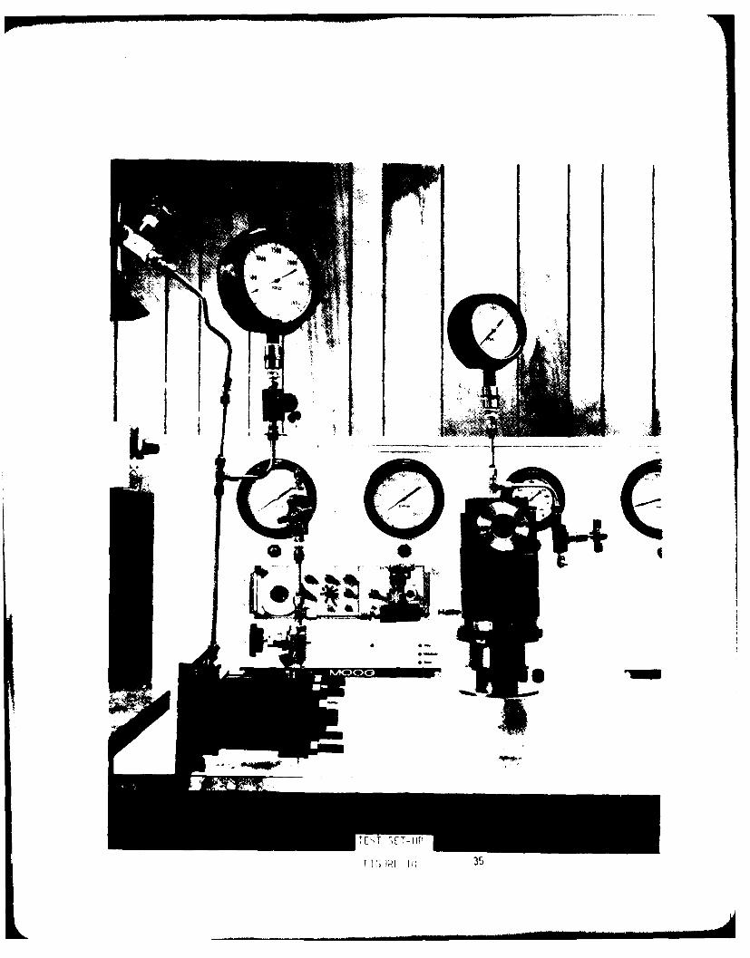
10 METAL BELLOWS CORP. TEST SET-UP 35
10a METAL BELLOWS CORP. TEST SET-UP 36
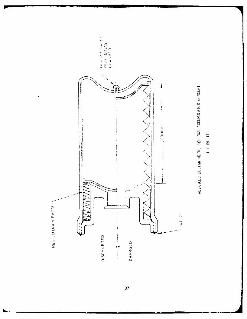
11 ADVANCED DESIGN METAL BELLOWS ACCUMULATOR 37CONCEPT
12 PROTOTYPE ACCUMULATOR DESIGN 38
13 BELLOWS ACCUMULATOR, 100 CUBIC INCH 39
EW/75420/Disk I/A8
8

LIST OF TABLES
TABLE NO. PAGE
1 BELLOWS TEST INFORMATION 40
2 ACCUMULATOR TEST SCHEDULE 41
EW/75420/Disk 1/Ag
9
1.0 INTRODUCTION
This document presents the results of the Low Maintenance Hydraulic Accumu-lator research program conducted under contract to the Air Force Aero Pro-pulsion Laboratory (AFAPL) by The Boeing Military Airplane Company.
The program objective consisted of analysis and evaluation of bellows shapesand characteristics, accumulator design studies and establishment of a proto-type design for interchangeability with existing accumulators.
The program was conducted in two phases. The initial phase consisted ofevaluation and testing of metal bellows configurations and the design of anaccumulator. The final phase included testing and evaluation of a 100 cubicinch accumulator housing.
Present day aircraft in military and commercial service are using accumu-lators in hydraulic systems for a variety of purposes including energystorage, surge damping, hydraulic pump size reduction and to provideincreased flow and pressure response to actuatibn subsystems. The number ofaccumulator applications has, however, been held to a minimum due to thedemonstrated unreliability of these devices and the attendant high main-tenance costs. The basic problem of existing accumulators can be generalizedas the inability to retain the gas precharge for a reasonable length oftime.
Recent advancements in metallic bellows technology including improvedfatigue life, new welding techniques and improved fabrication methods haveled to several successful applications in the aerospace industry. Currentstudies indicate that use of a metal bellows as a gas-oil separator haspotential for providing a reliable and consequently low maintenance costaccumlator. Use of an all-welded construction and hermetically sealed gaschamber will eliminate periodic accumulator precharge maintenance.
Experience obtained in development of a metal bellows reservoir for theBoeing Supersonic Transport (SST) and a follow-on program at Boeing MilitaryAirplane Company to develop a high pressure hydraulic accumulator providedbackground for this program.
EW/75420/Disk 1/B1
10
2.0 SUMMARY
This report presents the results of a program to develop a low maintenanceaccumulator using a metal bellows instead of a piston or bladder as thegas-oil separator. The purpose of the program was to develop an accumulatorwith a substantial increase in reliability and maintenance over existingconventional accumulators. Various concepts were evaluated for their abilityto meet design objectives. Devleopment of an appropriate metal bellows wasconsidered to be the critical task.
A bellows manufactured by the Metal Bellows Corporation (MBC), Chatsworth,California, was selected after a series of evaluation tests on candidatemetal bellows diaphragm configurations. Additional testing was conducted onMBC capsules to prove design capability prior to accumulator fabrication.Capsules testing indicated a diaphragm size of 2.97 0.D., 2.12 I.D. and athickness of 0.004 inches offered the best design concept based on anevaluation of 21 capsules by MBC. Results of the capsule testing showedpromise for attaining the accumulator design goal of a ten-year unservicedlife, based on F-16 service activity.
Additional effort was expended to design a hermetically sealed (all welded)accumulator compatible with the selected bellows capsule. Designs were inaccordance with criteria and requirements established in preceeding studies,evaluations and tests. The accumulator was designed to be equivalent infunction with existing standard MS accumulators. The final design is a 100cubic inch accumulator similar to the MS envelope and interchangeable withMS 28797-4. This unit uses a metal bellows as the separator and ishermetically sealed to provide reliability and does not require gages orgas charging equipment. This aspect eliminates all possibility of seal leaksand provides an accumulator insensitive to environmental conditions.
Accumulator testing included housing tests (impulse and burst) and vibrationof a full size bellows assembly. All tests were satisfactorily accomplished.Testing was concluded at this point due to time and budget constraints ofthe program. However, MBC will continue development with their own funds'ncluding full scale testing of a 100 cubic inch accumulator. This activitywill include oroof pressure, oottoming and endurance tests. Additionaleffort will be required to determine if orecharge monitoring is required,based on test results and system utilization aspects.
EW/75420/Disk 1/B2
11

3.0 DESIGN OBJECTIVES
The design objectives for the metal bellows accumulator were as follows:
o EnvelopeForm, fit and functionally interchangeable with the existing MSaccumulator
o WeightCompetitive with equivalent MS accumulator sizes
o EnvironmentOperational over a temperature range of -650F to +275 0F (compatiblewith a Type II hydraulic system)
o MaintenanceZero leakage of fluid or gas precharge (10-year service life - nomaintenance is the goal)
Simple precharge pressure monitoring methods
0 ReliabilityThe goal will be to provide the reliability required to attainfull service life without failure
o CostLife cycle costs significantly less than MS accumulator
o GeneralCompatible with applicable fluids and meet or exceed existingMilitary Specifications (except in cases of obvious conflict betweendesign and requirements which are directed specifically to MScylinder type units)
Design life at least three times that required by Military Speci-fications for existing accumulators.
EW/75420/Disk 1/B3
12

4.0 CONCEPT TRADE STUDIES
4.1 Bellows Design Evaluation
Technical data concerning the basic technology of welded metal bellows werereviewed concerning:
o Types of constructioni
- Welded- Formed material
o Diaphragm configurations
o Bellows characteristics
- Spring rate- Resistance to pressure, nested/extended- Long stroke capability- Stroke linearity
Figure 1 illustrates the various types of diaphragm configurations available.Some configurations are unacceptable due to inability to withstand highdifferential pressure in the nested position. The only acceptable con-figurations are the single sweep and the nesting ripple. Analysis methodsused to select metal bellows operational parameters are included in AppendixA. Figures 2 and 3 illustrate the critical problems during the discharged(nested) condition showing the critical load occuring on the diaphragm areaadjacent to the inside diameter weld of the convolutions. Figure 2illustrates nesting concepts and Figure 3 illustrates a ciining conceptdesignated to reduce the critical load area thus improving bellows life.
4.2 Bellows Selection
Proposals received from Metal Bellows Corporation (MBC), Flexible MetalHose Manufacturing Company, Sealol Incorporated, and Parker-HannifinCorporation were evaluated to select candiate suppliers of bellows capsuleassemblies for development testing. MBC and Sealol were selected to providemetal bellows capsule assemblies for endurance (bottoming) testing ofbellows configurations. The selections were made based on improvements indesign technology exhibited by both companies, with an attendant increasedpossiblity of achieving the design requirements. The MBC design incorporateda spacer providing a bearing column at the bellows I.D. The Sealol designutilizes "tilt-edge" to decrease the unsuported diaphragm gap at thebellows I.D.
4.3 Bellows, Test Fixture
A test fixture, Figure 4, for testing bellows capsules was desigted andfabricated. This fixture enabled installation of a test capsule to evaluateendurance (bottoming) cycles to permit design optimization prior to fullscale bellows development.
EW/75420/Disk 1/B4
13

4.4 Bellows Test Requirement
The original test plan consisted of 32,500 bottoming cycles to represent10,850 full stroke cycles in ten years, assuming F-16 usage of 355 sortiesper year plus two additional accumulator pressurizations per day for engineand system ground operation. A factor of three was imposed on this require-ment resulting in the 32,500 cycle requirement. The bottoming testsimulates a normal pressure shut-down of the aircraft hydraulic system.With pressure shut-down, the bellows which is pressure balanced duringoperation of the hydraulic system, is compressed to its stacked position bythe hermetically sealed gas charge. The gas charge then exerts an externaldifferential pressure on the stacked bellows. The bottoming cyclegoal/requirement was reduced later in the program to 15,000 cycles as theoriginal objective of 32,500 cycles was considered too severe. This wasagreed upon during discussions between Air Force and Boeing personnelrelative to the actual usage of aircraft. The requirement for 15,000 cyclesis considered to be representative of F-16 operation.
EW/75420/Disk I/B5
14
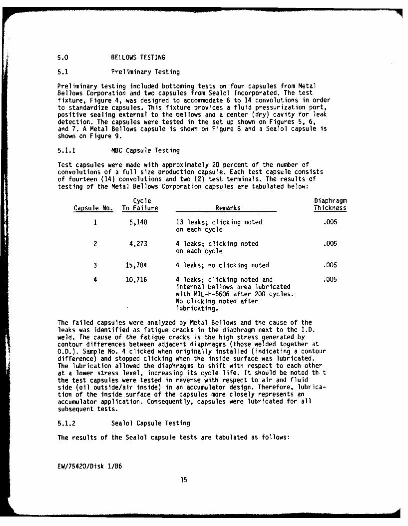
5.0 BELLOWS TESTING
5.1 Preliminary Testing
Preliminary testing included bottoming tests on four capsules from MetalBellows Corporation and two capsules from Sealol Incorporated. The testfixture, Figure 4, was designed to accommodate 6 to 14 convolutions in orderto standardize capsules. This fixture provides a fluid pressurization port,positive sealing external to the bellows and a center (dry) cavity for leakdetection. The capsules were tested in the set up shown on Figures 5, 6,and 7. A Metal Bellows capsule is shown on Figure 8 and a Sealol capsule isshown on Figure 9.
5.1.1 NBC Capsule Testing
Test capsules were made with approximately 20 percent of the number ofconvolutions of a full size production capsule. Each test capsule consistsof fourteen (14) convolutions and two (2) test terminals. The results oftesting of the Metal Bellows Corporation capsules are tabulated below:
Cycle DiaphragmCapsule No. To Failure Remarks Thickness
1 5,148 13 leaks; clicking noted .005on each cycle
2 4,273 4 leaks; clicking noted .005on each cycle
3 15,784 4 leaks; no clicking noted .005
4 10,716 4 leaks; clicking noted and .005internal bellows area lubricatedwith MIL-H-5606 after 200 cycles.No clicking noted afterlubricating.
The failed capsules were analyzed by Metal Bellows and the cause of theleaks was identified as fatigue cracks in the diaphragm next to the I.D.weld. The cause of the fatigue cracks is the high stress generated bycontour differences between adjacent diaphragms (those welded together atO.D.). Sample No. 4 clicked when originally installed (indicating a contourdifference) and stopped clicking when the inside surface was lubricated.The lubrication allowed the diaphragms to shift with respect to each otherat a lower stress level, increasing its cycle life. It should be noted th.tthe test capsules were tested in reverse with respect to air and fluidside (oil outside/air inside) in an accumulator design. Therefore, lubrica-tion of the inside surface of the capsules more closely represents anaccumulator application. Consequently, capsules were lubricated for allsubsequent tests.
5.1.2 Sealol Capsule Testing
The results of the Sealol capsule tests are tabulated as follows:
EW/75420/Disk 1/B6
15
Cycle DiaphragmCapsule No. To Failure Remarks Thickness
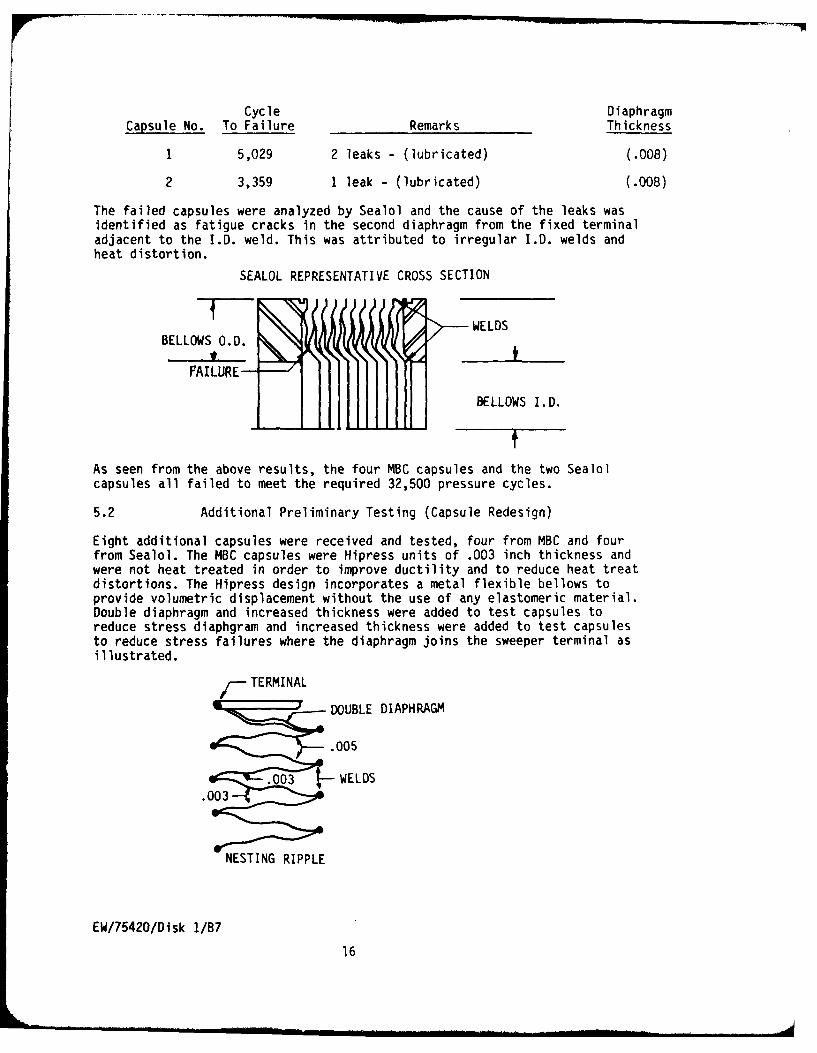
1 5,029 2 leaks - (lubricated) (.008)
2 3,359 1 leak - (lubricated) (.008)
The failed capsules were analyzed by Sealol and the cause of the leaks wasidentified as fatigue cracks in the second diaphragm from the fixed terminaladjacent to the I.D. weld. This was attributed to irregular I.D. welds andheat distortion.
SEALOL REPRESENTATIVE CROSS SECTION
BELLOWS O.D. WELDS
FAILURE--
BELLOWS I.D.
As seen from the above results, the four MBC capsules and the two Sealol
capsules all failed to meet the required 32,500 pressure cycles.
5.2 Additional Preliminary Testing (Capsule Redesign)
Eight additional capsules were received and tested, four from MBC and fourfrom Sealol. The MBC capsules were Hipress units of .003 inch thickness andwere not heat treated in order to improve ductility and to reduce heat treatdistortions. The Hipress design incorporates a metal flexible bellows toprovide volumetric displacement without the use of any elastomeric material.Double diaphragm and increased thickness were added to test capsules toreduce stress diaphgram and increased thickness were added to test capsulesto reduce stress failures where the diaphragm joins the sweeper terminal asillustrated.
TERMINAL
:r DOUBLE DIAPHRAGM
.005
.003 WELDS
.0R0 3
NESTING RIPPLE
EW/75420/Disk I/B7
16

Testing was accomplished on the MBC capsules and all four capsules failedto meet program objectives. Results are tabulated below.
Cycle DiaphragmCapsule No. To Failure Remarks Thickness
5 1 5,126 Probable failure due to fatigue .003cracks generated by adjacent
6 1 6,814 diaphragm contour differences.
7 6,562
8 1,025 Manufacturing discrepancy .003
1 floating terminal stop removed - floating terminal failed - bellows wasokay.
The four Sealol units were "tilt-edge" configuration on the I.D. weld andstraight configuration on the O.D.
The four Sealol capsules also failed to meet program objectives. Test resultsare tabulated below.
Cycle Diaphragm
Capsule No. To Failure Remarks Thickness
3 8,519 Probable fatigue crack failure .008
4 7,643 Probable fatigue crack failure .008
5 500 Failure mode not identified .005
6 700 Failure mode not identified .005
5.3 Preliminary Testing Conclusions
Preliminary testing has indicated problem areas in manufacturing techniquesincluding die design and assembly practices.
o Testing of capsules showed inability to meet the program objective(32,000 cycles at 0 - 2000 psi alternating pressure).
o The MBC design, .005 diaphragm thickness, exhibited the greatestpromise with one capsule reaching approximately 50 percent of thedesign goal.
o All BMC capsules illustrated failures due to contour differencesprobably caused by a mismatched diaphragm, one concave, one convex,formed in different dies.
o The Sealol "tilt-edge" design functioned best using .008 thicknessfor the diaphragm. However, testing indicated only 25 percent ofthe desired pressure cycles were achieved.
EW/75420/Dlsk 1/88
17
iA

6.0 PROGRAM REVIEW
After completion of preliminary testing, program review was held at WPAFBwith Boeing and AFAPL personnel to assess program results and to develop afollow-on plan. The following plan was developed as a result of this review.
0 Four additional advanced design MBC Hipress capsules would bedesigned, manufactured and tested. The four capsules would bematched, neutered pairs of diaphragms. The capsules would beassembled with close attention to the concentricity of the matchedpairs since failures to date indicate contour interferences. Thiswill require the design and manufacture of a special set ofneutered dies, concentricity control of O.D. and I.D. during weld-ment and identification and matching of diaphragm pairs.
o Testing will be conducted using 0 - 2000 psi alternating pressurecycles and internally lubricating the bellows.
o Program continuation, including accumulator fabrication, will bedetermined based on results of the capsule testing.
EW/75420/Disk 1/89
18

7.0 ADVANCED DESIGN TESIINb
The four bellows capsules were manufactured by MBC and tested at Boeingwith the following results.
#1 failed after 7,063 cycles
#2 failed after 11,123 cycles
#3 failed after 7,727 cycles
#4 failed after 4,324 cycles
All leaks were in the first transition convolution from the floating endterminal. The cause of failure was determined to be a mismatch between thefloating terminal ripple contour and the contour of the first transitiondiaphragm.
7.1 Metal Bellows Corporation Testing
Because of program cost considerations, all subsequent development testingwas conducted at the Metal Bellows Corporation in Chatsworth, California.
7.1.1 Advanced Design, Bellows Testing
The MBC bellows tests were conducted on the test set up shown in Figure 10.New tooling was made for diaphragms weith an O.D. of 3.25 inches and anI.D. of 2.40 inches. Tests 5 through 16, Table 1, were performed on testcapsules made using the new tooling. Several design and manufacturingvariations were evaluated. Tests 14 and 15 indicate that .004 inch thickmaterial is suitable for meeting a 15,000 bottoming cycle requirement. Thefinal diaphragm size, 2.97 I.D. by 2.12 I.D. was selected to satisfyenvelope requirements of MIL-A-5498 specifications. Test No. 17 resulted ina bottoming cycle life of 12,000 cycles. A different manufacturingtechnique was used for Test 19 and 20, using the same material thickness asTest No. 17.
Two test capsules (see Test No. 19 and 20 of Table 1) were installed in atest housing. The gas side of the bellows (external) was pressurized to2000 psig nitrogen and sealed off. The oil side of the bellows (internal)was pressure cycled to extend the test capsule to its normal operatinglength and back to the bottomed position with 2000 psig differentialpressure acting across the compressed capsule. Test No. 19 was stoppedafter 32,5000 cycles for examination of the bellows. The gas chargepressure did not decrease from the start of the test. The capsule was foundto have a leak detectable with a helium mass spectrometer. Test No. 20 wasstopped after 20,000 cycles. A helium leak was also found, but the test wascontinued. After 31,000 cycles, a decrease in gas pressure was observed.
Inspection of Table I, (Test 14 through 21) indicates accomplishment of thedesign goal of 15,000 bottoming cycles. Test No.'s 14 and 15 of Table Ishows that .004 inch thick diaphragm material is satisfactory in a 3.25O.0. capsule. The production size, 2.97 O.0. is demonstrated by Test No.'s19 and 20. Test No. 21 shows that .003 inch thick material may also beacceptable.
EW/75420/Disk 1/810
19

7.1.2 Endurance Testing
The endurance test simulates normal operation of the hydraulic system.Capsules were not subjected to the endurance test as this requirement isconsidered to be met by analysis. The capsule is designed to be near itsfree length at operating conditions. The conditions of the endurance testproduce a balanced pressure across the bellows resulting in no pressurestress on the bellows. The bellows motion resulting from pressure cyclingbetween 2600 psig and 3000 psig does not produce a stress high enough tolimit the life of the bellows.
7.1.3. Vibration Testing
The vibration test was conducted using a full-sized bellows assembly. Analuminum test housing, with inside dimensions identical to the flighthousing, was used for the vibration test. The aluminium test housing wasbolted together such that it could be disassembled to provide access forbellows examination. The test housing was also reusable for other types oftesting.
Although not required by existing accumulator specifications, vibrationtesting per MIL-STD-810C, Method 514.2, Procedure I, Curve L was chosen torepresent a possible severe environment. Test housing, P/N 77907, with arepresentative Bellows Assembly, P/N TC 77882, was subjected to adverseeffects of the test.
The results of this test were satisfactory with the bellows showing no signof physical damage (Reference Appendix B).
EW/75420/Disk 1/Bl
20

8.0 ACCUMULATOR DEVELOPMENT
8.1 Design Considerations
Various accumulator configurations were evaluated to determine optimumdesign considering the following variables:
o Bellows outside diameter (limited to MS constraints)
o Bellows inside diameter
o Mean effective diameter of bellows
o Number of bellows convolutions
o Material selection
o Material thickness
o Heat treat effects
o Position of bellows during heat treat
o Precharge pressure
o System pressure
o Temperature
Results of these studies indicated a short, large diameter accumulator mayafford the best configuration. However, due to design constraints of currentMS accumulators, a configuration similar to the MS accumulator wasdesignated. Figure 11 provides a conceptual description of an advanceddesign metal bellows accumulator.
8.2 Accumulator Design Requirements
The following design requirements were established to be in conformancewith MS 28797-4, permitting interchangeability of accumulators with respectto envelope and function.
o The 100 cubic inch accumulator design is interchangeable witheither part number MS 28797-4 (Procurement Spec. MIL-A-8897) orpart number MS 28700-4 (Procurement Spec. MIL-A-5498).
o Clamps to install the Metal Bellows accumulator will be the same
as those used with MS accumulator.
o Operating Pressure: 3000 psi
o Operating Temperature: -65OF to +275 0F
o Cold Start Conditions: 3850 psig and -65OF
o Proof Pressure: 4500 psig at 100OF
EW/75420/Disk 1/B12
21

o Burst pressure: 12,000 psig at 100OF
o Gas Charge Leakage: Below 10-8 cc/sec (lose 38 psig max in 10years)
o Gas Charge Volume: 10 + 8 cu. in.
o Installation: 3.219 Max Clamp Diameter
o Housing Material: 4130 alloy steel
o Bellows Material: AM350 Corrosion Resistant Steel
8.3 Accumulator Test Requirements
Test requirements for the accumulator are listed on Table I. Test require-ments are directed at an accumulator life of seven to ten years based on15,000 bottoming cycles.
8.4 Accumulator Design
A prototype accumulator design was accomplished for a 100 cubic inch accumu-lator as shown in Figures 12 and 13. This design featured a concept using agas side charging tube to be crimped after proper precharge and a non-weldedconstruction to provide disassembly and inspection after testing. The finaldesign would be all welded construction to preclude leakage problems evidentin standard accumulators.
The metal bellows accumulator design is a significant improvement in state-of-the-art accumulator design. No periodic checking of charge pressure orrecharging to make up for lost gas charge are required. Also eliminated isthe frequent complete overhaul to replace worn seals (0-rings). Additionalefforts to evaluate means of monitoring precharge pressure were notaccomplished due to budget and program constraints.
8.5 Accumulator Tests
Testing of an all-welded accumulator housing was performed. The housing wasidentical to the production unit and successfully demonstrated the integrityof the design concept. (Reference Table II.)
8.5.1 Housing Tests (Appendix B)
The 100 cubic inch flight accumulator housing, used for testing, isidentical to the production design with the exception that the area ofinternal bellows attachment was not machined to match the bellows. Theexternal finish of the test housing was left unplated. These two exceptionshave no effect on the structural integrity of the accumulator housing. Abellows was not installed within the test housing for these units.
8.5.2 Proof Pressure
The accumulator housing (See Figure 12) was pressurized to 6000 psi for oneminute. There was no evidence of leakage or permanent deformation.
EW/75420/Disk 1/B13
22

8.5.3 Burst
The accumulator housing was subjected to a burst pressure of 12,000 psig.There was no evidence of leakage or rupture.
8.5.4 Impulse
The accumulator housing was subjected to the pressure cycling test inaccordance with the requirements of MIL-A-8897A, paragraph 4.7.5, Table I,Step 7. There was no evidence of leakage or permanent deformation. (SeeWyle Laboratories Data Sheet Report No. 55556, Appendix C.)
EW/75420/Oisk 1/814
23

9.0 CONCLUSIONS AND RECOMMENDATIONS
9.1 Conclusions
This program developed the critical portions of an advanced low maintenanceaccumulator. The design and testing of metal bellows test capsules demon-strate the capability to fabricate a metal bellows capsule capable of with-standing six to ten years of service life. Additional development andtesting of a 100 cubic inch accumulator housing demonstrated the ability tomanufacture an all-welded (sealed) accumulator. The evaluation includedproof, burst and impulse testing of the accumulator housing withsatisfactory results. Housing tests met requirements in accordance withMIL-A-8897-A.
Life cycle cost analyses, conducted as part of the proposal effort, supportthe development and usage of an improved low maintenance accumulatorincorporating a sealed housing and welded metal bellows gas/oil separator.Results of the studies showed a potential cost savings of $11 million overthe lifetime of the F-16 fleet.
9.2 Recommendations
The program should be continued to fully develop and test a production,flight worthy accumulator. A prototype accumulator should be fabricated andsubjected to bottoming and endurance tests. This unit should be monitoredto provide test and design data for a flight worthy accumulator. At theconclusion of testing, several flight quality accumulators should bemanufactured and subjected to flight clearance testing. Investigationsshould also be made to provide gas piecharge monitoring capability usingdevices that will not compromise the integrity of the all-weldedaccumulator. Weight and cost reduction studies should be included toprovide the best possible competitive unit.
EW/75420/Disk 1/815
24

LUCl
Cl -LLJ frlU C
ILU
LJ
C)I-J
ciI- , -:
CA:
LL-J
LU cn
C3
ci0-LL-1
cirC
25

B-B
G
S
ACCUM4ULATORASSEMBLY A-A
BELW NETN C GRCTRSGC
B-B FIGURER2
26

-JA
LaL
LU u
L- a:
ca CD-i-
-JJ L:x,
-JL
LJLo
27I .

-. 0/32 '0'RN SURFACES)
6 MIN CONVOLUTIONS
4.504.50 DIA. "
DIA
- SYM.
IL. SWEEPER TERMINAL SUPPORT HEIGHT TO SPECIFIEDFOR EACH SAMPLE (NESTED BELLOWS)
/2 SWEEPER TERMINAL THICKNESS "t" MUST SPAN CDIESOWITHOUT PERMANENT DEFORMATION WITH 4000 PSI APPLIFO TOTHE OUTSIDE OF THlE BE.LLOWS IN THE NESTED CONDITION
28
FIGURE 4

flzw

UI. Lli
W
W a:>0
<i 0'-0 >
LJw
IJ-i->
F - c (fL)
i-c< LOJ
z CD
C-i-
Lw H
LL,-N LLL.'
L
3U0

1Mw


33

34
SEALOL INC. ILET CAPSULE
FIGURE 9
IMOW
3C

C'AMSER
~9
F N"-s F E la
CYCL-INCA \ALVC-
fec. Kv ot ri
TEST SET-UP
FIGURE 10a
LII-
LIi
CL-
Q)~
cLU
37 -

-El
4'D
C>3
LD
Ix -
ca ~ UJ
cn -I- I- k
38~

.7L
39

oo0) 0 4J 0
- 0 !r- 0
'A (A 00 tA U >l4) E E w) c0 0
t 4 4-1 04 S. L -0-m 00 C c0
r- 0.0 .0 '. ; ~ 4-4J 0),2 0 4-' 0 0 A-- ._C -0 ) ) 0 0
cc Co W 4- 4J 4-J CL 0.0 4.) :3 $-, 0 u- 0 s- &A0) 0 A4
0 41 -t 4J-Z 4J 4J4 M M k S- 44 4-3 4J .44E m CLO to to M m. 0 0 44eo 0 00.0 0 E E V) 0.. i. ~L
0) 4-0 C C 0 0a 0 ) w)44 >. 4 - 4 -" . - -
U' C C LA C C U' C. 0 0 0 0 00) 0 Q)30) to 100w0 0 w00 C0
m' mC r- - 0C C M 0,mC 0 mC C D >C 000 0 0 0 0 0%0 4CMj CMi CMi 0- 0 CD CM- C0 0 0 0 0 0 0 0 0 0 CD0.- Ili 1% 00 4C 04i .- C% t (4 LA LAi 00 LAi 00-
CM CM0) 0 C14 CO m -C m
W - .-4 C% C CM -4 m m m
CD C CM M C M .4 .4 4 ,C j (
4-i I I I I I I I I IC0 0 0 0 0 00C0 00CDC)C C)0
L.. ' 0 0 0 0 CDO 80 0 0 0 0 0 0 0
s. 4CM I'I :- . CMj m - L o q0z- m LA) k'0C 00m i 0
c Lc) Lo LA ULA Lo Lo LA LA Ln Lo r -0 -0- -0-0- LA --
4.1 9 9.
In r CM c CDM CM C CM C)-- 0 0-0 0 0 0 0 0 C> a04 .-4 CN
m' C') mn m' Ci cMi Cj CM\I C C j CM I CM CMC CM c CM) CM CMj CM
- - - - LA LA LA LA LA) LA L L uLA LA LA LA CM CM CM CM CMCM % CMi CM CM CM! C CM CM CM! CM! CM CM CM! CM CM 0: 0: 0: 0404
LA4 LA LA LA C) ') ON) ON) c) 0% C) M' I-1 ") C)' CM C M 0CM CM CM
C-)
* "I
40 CC fCM R Lr) %D PC')C'%)C C \') 0-0-0-0-0 0- C') 00 C') C)
400

w -DC, LJ k C 0 C)U- I- j
0 ~ r OO U 0 4
L&i.
0 0
C> ~ i 0nV C L
wi w
Q- m-
L) U -- CL
LLW LL- L')J
V)) V
C~cLU LU 4LU
V), LA V) C
CL~~ CL. -oLJ ~0.. 0 %.
V) I~ LU LUOL)J 3c H
LU Lk0
0.0. ~ U -4C41(

APPENDiX A
ACCUMULATOR ANALYSIS TECHNIQUES
42

APPENDIX A
The following is a description of the bellows fluid pressure of 3,000 psig at 750 F.analysis me thod to de termine majoroperational parameters. Many of the details are Taking the bellows spring rate intoavailable from metal bellows manufacturers considerationand can be applied to the accumulator design.
Precharge Pressure = P2 + PBBellows Parameters
Where: P2 is final precharge pressure (psig)Outside diameterInside diameter PB is pressure to compress bellowsDiaphragm spca (psig)Effective areaDiaphragm configuration Calculate precharge gas volume (V1 )MaterialCondition of material P2 V2Number of convolutions V1 = PIThickness of material
Standard convolutions The equivalent bellows stroke (XB) for aTwo adapter convolutions at each end displacement of 100 cubic inch('s can be
Spring rate calculated as follows:Natural frequency (lonqitudinal) - dry
Both ends fixed AV
Calculate the bellows spring rate (KB). AB
K K h3 1. D.- N Determine the bellows separator displacementB X-- .D N ( AV ) with a gas precharge of 1.500 +50 ;psi
at 75%F when charged with hydraulic fluid atWhere: Kx is constant from empirical data -65°F and 3000 psi.
h is material thickness (inches)I.D. is inside diameter AVB V1 . V2N is number of convolutions
Where: V1 is gas volume at 1,500 ±50 psi (in.3 )
Determine the differential pressure required to
stroke the bellows from its free position to the V2 is gas volume at 3,000 psi (in.3)completely compressed position. V PI VIT2
XB (KB) P2 TIDifferential Pressure - AB
Where: P1 is initial pressure (psi)Where: XB is bellows travel (In.)
AB is bellows effective area (in. 2) P2 is compressed pressure (psi)
Determine the initial precharge pressure and T, is initial temperature OR
gas volume required at 750 F to provide the T2 is final temperature ORrequired fluid displacement with a system
43

The equivalent bellows travel may be Where: K is bellows spring rate (lb./in.j
calculated as follows: W is bellows weight (lbs.)A~vXB AB N .5 386 (30)
B 4.5
The gas end dome requires sufficient space to = 25 CPS
insure against the separator bellows bottoming Bellows and gas charge system, schematicallyout on the gas end. represented as shown below:
Calculate the increase in the precharge pressure KB KG
due to the rise in temperature from 750 F to rn A
300 0 F. P PTrl KBKG
T2 - rn
P = PI T 2
TI Where: m is mass of bellows moving header
Calculate the decrease in the precharge pressure (lb./sec. 2 /in.)due to drop in temperature from 75°F to-65 0 F. PI T2 K is spring rate of gas charge
P2 T (1./in.) and is defined asT1 .AP (A8 )
Calculate the maximum differential pressure Kg XB
which may be applied internal to the separator XB
at its maximum extended length without Bellows Life Cycle Equationsinducing ''squirm" or canting of theconvolutions. The alternating and mean stress levels are
- KB calculated as follows:
L L (Max. Stress) - (Min. Stressl
Where: Cs is a constant from empirical data Alternating Stress = 2
Calculate the maximum fluid pressure (PM) the (Max. Stress ) + (Min. Stress)bellows can withstand internally at the three Mean Stress 2temperature points: 275 0 F, 750 F and -65 0 F.
The precharge pressure will be considered to be The maximum and minimum stress levels arethe minimum of 1500 psig at 750 F. The calculated by the following formulae usingbellows maximum displacement will bc taken constants Kp, KpC, and Kx derived from
at the position at -65 0 F and 3000 psig. empirical data.
P1 V1 T2 NOTE: The maximum and minimum stressPM V T1 levels given are fur the I.D. weld joint.
21 The I.D. joint is the maximum
Calculate the natural frequency (Nf) of the stressed joint in this application.beiows and gas charge system.
Pressure stress formula tor proof and burst
Bellows only, both ends considered fixed. pressure conditions:
SW SP P K p t
44

Where: Sp is pressure stress (PSI) Where: SX is deflection stress (PSI)
KX is stress constantP is applied pressure (PSI) X is bellows deflection (In.)
N is number of convolutionsKI is stress constant
Calculate the stress on the bellows I.D. jointI.D. is bellows inside diameter (In.) under proof pressure external: (at 275 0 F)
t is material thickness (In.) NOTE: The pressure stress is tensional (4) andthe deflection stress is compressive (-).
Pressure stress formula for bellows under They are summed algebraically.pressure cycling conditions:
r .D] 2 Pressure stress at proof:
P L--jJ r, 2X I t [ 1.-]J
Deflection stress formula: X SP PKp
Kx(N) I.D.2
45
CR 715
APPENDIX B
AETL REPORT NO. 543-8901
EW/75420/Disk 1/B34
46

Report No. 543-8901P.O. No. 90313Date: 4 September 1980
Metal Bellows Corporation20960 Knapp StreetChatsworth, CA 91311
TEST SPECIMENS
One (1) High Pressure Housing Assembly, Part Number 77907, Serial Number01.
SUMMARY
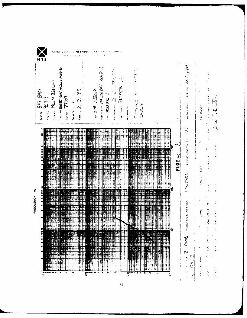
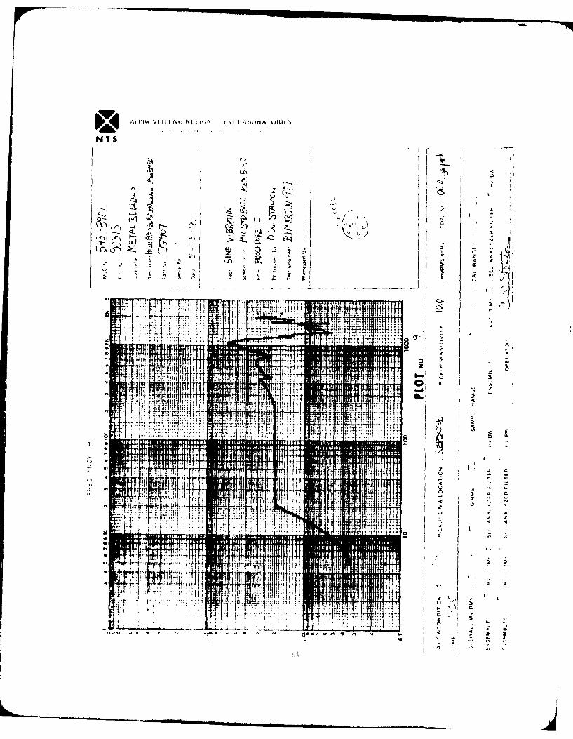
This report certifies that the test specimen identified above has been sub-jected to Vibration Testing in accordance with MIL-STD-810C, Method 514.2,Procedure I, Curve L. All results conformed to specification requirementsand no adverse effects were noted.
TEST EQUIPMENT
AETL No. Manufacturer Instrument
D526V Endevco Corporation Accelerometer; M/N 22460613V Unholtz-Dickie Corp. Servo Programmer; M/N SP-5D681V Endevco Corporation Charge Amplifier; M/N 2720PRSD731V F. L. Moseley X-Y Plotter; M/N 135D762V Endevco Corporation Charge Amplifier; M/N 2720PSD763V Hewlett-Packard Log Voltmeter/Converter; M/N 7562AD997V Endevco Corporation Accelerometer; M/N 2246D1024V MB Electronics Power Amplifier; M/N T999 MODD1025V Unholtz-Dickie Corp. Sweep Oscillator; M/N OSC-1D1115V Spectral Dynamics Corp. Dynamic Analyzer; M/N SDIO1AD4018V MB Electronics Vibration Exciter; M/N C210P628V Ashcroft Pressure Gauge; M/N 1079P683V Ashcroft Pressure Gauge; M/N 5000PSI
NOTE: The equipment specified above was calibrated, as required, inaccordance with MIL-C-45662A, with traceability to the NationalBureau of Standards (NBS). The NBS traceability records are main-tained on file in the AETL Quality Control Office.
EW/75420/Disk 1/B35
47

Report No. 543-8901P.O. No. 90313
TEST PROCEDURES AND TEST RESULTS
Vibration Test
Date Commenced: 7 August 1980Date Completed: 14 August 1980
The Assembly was installed in a test fixture and rigidly mounted on a vibra-tion exciter. The Assembly was then subjected to a sine resonance survey,in each of the three major orthogonal axes (refer to Figure 1), at an inputlevel of 0.1-inch da up to a limiting value of 2 g's peak over thefrequency range of 5 to 2000 Hz. The sweep rate was one octave per minute.Resonances were found in all three axes. During the resonance search, thehousing was pressurized to 2000 psig with gaseous nitrogen and the bellowswas pressurized to 3000 psig with oil.
On completion of the resonance search in each axis, the Assembly was sub-jected to 30 minutes of frequency dwell at each of the critical resonancefrequencies (maximum of four) at the following levels:
Frequency (Hz) Levels
5 - 14 0.1-inch da14 - 23 1 g's peak23 - 104 0.036-Inch da
104 - 2000 20 g's peak
Refer to Table I for the Frequency Dwell Schedule. During the frequencydwells, the housing was pressurized to 2000 psig with gaseous nitrogen andthe bellows oil pressure was cycled between 2600 and 3000 psig at a rate of60 seconds per cycle.
The Assembly was then subjected to 2 hours of frequency cycling at thefrequency dwell vibration levels. The sweep rate was 5 to 2000 to 5 Hz in20 minutes. The combined cycling and dwell time in each axis was 3 hours.
EW/75420/Disk 1/836
48

Report No. 543-8901P.O. No. 90313
The Assembly was visually examined on completion of testing, and no sign ofphysical damage waas noted. X-Y Plots were recorded during testing and arepresented in the Appendix. This concluded testing and the Assembly wasreturned to Metal Bellows Corporation.
WILLIAM H. HOYT, V.P. Quality Assurance
EW/75420/Dlsk 1/837
49
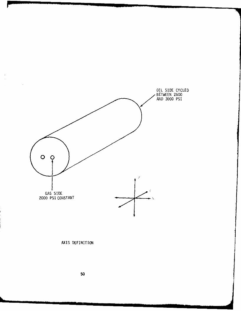
OIL SIDE CYCLEDBETWEEN 2600MND 3000 PSI
10GAS SIDE
2000 PSI CONSTANT
AXIS DEFINITION
50

Report No. 543-8901P.O. No. 90313
TABLE I
Resonance Dwell Schedule
Axis Frequency (Hz) Input Level (g's) Output (g's) Duration
X 1187 20 96 - 100 30 min
1398 20 130 - 140 30 min
V 600 20 100 - 110 30 min
981 20 110 1 min
945 20 130 2 min
942 20 120 - 110 11 min
958 20 115 2 min
934 20 110 6 min
942 20 120 1 min
920 20 105 7 min
Z 1200 20 80 - 82 30 min
1575 20 190 - 170 30 min
EW/75420/Disk 1/839
51

APPENDIX B
X-Y Plots
EW/75420/Dlsk 1/B40
52
*1141tovEDt~k; IN ' i I At)It A IU (I
NYTS
I_ A
> x..
It! i lt Isz 'I lit Z
I. I
21i
lit!
53

AP W V, i N6INE EH IN 'II AMIT A( I I I I ,
14 TAA
Ln 9A' 7'
ci-r
LL
414
I I'U 1 I
544

AlIIH)k 'E ( ,INfHN ,I I~ lI 4il
'L'1
.ml -
- C '-'
rm 11w- a-min Ira
Fl.~
r -
I _______

~4 API'14tVE EIiN(.INt E Hl %I t AHOH A 10($41 S
NTS
Fc
0 z
-ai E
Lai.
14
56T

APPOVE ENINERIN Sl AHOIIAYOIES
NTS
FcJ
> W
cr
C 4
Z 4
I
I H,
0
u- j cr~
fir MA
57

AVIVI P) I NkINI CHIN S I ABII4 A 14)141
Ld >
11 L1
......... ~ :; ti;

APIM~t 0 t Nk.INiI t IN I mitI~IIl jI ',
~4.i4
It ItH
313
tzm P. 'oo 0 A 0
3 - V59

-kIt t IV k N ,i NL k $ t is~ t I t I Ii It
U--.
q dc
W*~* it I -
0'
1;4
tt
'IT
I, 09
C) ' ~
MA.
A&TIWV L) k NkINt t fill t ,I I AtsmiA ImIill
NTS
jI jIL _
~ 1 7.H
0
ITI
.1 a
INN"
~ ~17
All,
A2

TN 1,1
...... ...
V n"-~
T U,
ca
622

NTSt
if ~T;I-4 * \ CL
Ixj ~ --
7Tc -
&6

DATASHEE1 2EPORT No. 55556
WU L J -ABOHOADWIES
May 23, 1980
Metal Bellows Corp.20960 Knapp StreetChatsworth, CA 91311
ATTENTION: Mr. John HuffmanTEST TITLE: Pressure Cycling and EnduranceREFERENCES: Your Purchase Order No. 89727
Wyle Laboratories Job No. 55556Government Contract No. N/A
Gentlemen:
This is to certify that the enclosed Test Data Sheets cont-in true and correct data obtained inthe performance of the test program as sat forth in your purchase order.
Where applicable, instrumentation used in obtaining this data has been calibrated using standardswhich are tTaceable to the National Bureau of Standards.
Test Results.
One Accumulator, P/N 77189, S/N Qual 1, was 5ubjected to the Pressure Cyclingand Endurance Test in accordance with the requirements of MIL-A-8897 A, Paragraph4.7.5, Table I, Step 7. The specimen complied with specification requirements.The enclosed data is presented for your evaluation.
Enclosures: Data Sheets (I Pages) ; Equipment List (1 Page)
SIATF OFCALIkOUNIA c'OUNTY OF LOS ANGELFS . DEPARTMENT Mechanical Systems
C. D. Yiakas, Department Manager .beingdulysworn,deoses end says: That te itrurmation contained in this reporti is the result ofcomplete 8n carefully I dond led tesIs and is so the best of his knowledge trueand c arvee Is "alt re . / . TEST ENGINEER
('- (-~/7A ~ .Snow
TEST WITNESSsu p.'lelt worn 1. belor me 7aye May . 90
"T= . . ., Not Applicable
--- DCAS-QAR VERIFICATION
W~' OAYPuOt C -CALIFORNIA Ij.// Yc CONTROLLO ANGELES COUJNTY IAYnebr.J. 64 QUALIT OTO
isbn CEpi-es July 27. 1982

Report ':n. 35556Page No. 2WYLE LRONA1,8&141S1F
DATA SHEETTeitlo: Pressure Cycling and Endurance
C¢atomor Metal Bellows Corp. JOS. No. M-55556
Specimen Accumulator Onto Tet Sta.rted 5-16-80
Pori No 77139 Dat, Test CmpJ.+ 5-22-80S/N Qual I Amb. Tamp 70 t 10 0 FSpec. MIL-A-8897A Photo No.Par&. 4.7.5, Table I, Step 7 Toot Mod. MIL-H-5606
Spoclen Temp Room Ambient
Precedure and ResulLs:
The specimen was installed in a test system similar to that depicted in Figure2 of the above referenced specification. The svstem was adjusted so that apressure rise rate of 125,000 to 200,000 psi per second w:as achieved. Thespecimen was then subjected to 1,000,000 pressure cycles from 2,000 psi maimumto 3,000 psi minimum at a cycle rate of 143 t 2 rpm. The test fluid was maintaindat 100 ± 150 F for the duration of the test. Upon completion of the '1,000,000pressure cycles, the specimen was removed from the test system and visuallyexamined. There was no apparent damage, degradation or deformation. A typicalpressure cycle, including the rise rate, is shown below.
3000 ln lnn ,j *Typical Cycle
a. **Typica1 Rise Rate
ImmmEE.,E-.E' I2000
Tooted By .4
Spocimoa moots Spoc. ftequlrome'it YES at Wriftell____________No C] 65 she No- f __________
a&A Q. C. Form Approval &6 ......... Appovd Do,. 523
U S GOVERNMENT PRINTING OFFICE 1g81 75M4

,DATE
I .LME