Embed Size (px)
Citation preview

TDS0170 Issue 1.6 13/08/2019 Change note 636 Page 1 of 13
FEATURES
High resolution infrared sensor measures methane from 0 to 100% volume with a resolution
of 0.01 % for 0-5% methane and 0.1% for 5-100% volume.
Can be configured for either methane, 0-100% or propane 0-2% volume measurements.
Combines all the features of the well-proven range of Premier hydrocarbon sensors, enabling
the accurate measurement of 0-100% vol. methane with one sensor.
Offers reduced response times when compared with earlier versions.
Contains all the necessary optics, electronics and firmware to provide a linearised,
temperature-compensated output for both methane and propane.
Choice of output format – digital output (floating point and binary), or industry hi 0.4 to 2
volts.
User configurable using USB powered Premier Configuration Unit.
Analogue output is scaleable in % volume or % LEL.
Enhanced EMC protection
Internal Flash memory allowing sensor firmware updates via configuration equipment.
Dynament Limited
Hermitage Lane Industrial Estate ٠ Kings Mill Way ٠ Mansfield ٠ Nottinghamshire ٠ NG18 5ER ٠ UK.
Tel: 44 (0)1623 663636 ٠ Fax: 44 (0)1623 421063
email: [email protected] ٠ www.dynament.com
LOW POWER 2 VERSION TRIPLE RANGE HYDROCARBON SENSOR
Exd Certified versions
Current consumption 8mA at 3V dc Uses the same proven technology as the existing Dynament sensor range Drop-in replacement No loss of performance
MSH2-LP2/HC MSH2ia-LP2/HC
Technical data sheet TDS0170

TDS0170 Issue 1.6 13/08/2019 Change note 636 Page 2 of 13
Patent Protection
The sensor design is protected by the following Patents
Great Britain GB 2 401 432 & GB 2 403 291
Europe EP 1544603 & EP 1818667-Pending
France EP [ FR ] 1544603
Germany EP [ DE ] 1544603
Italy EP [ I ] I1544603
Switzerland EP [ CH ]1544603
USA 7, 244, 939
Other World Patents Pending

TDS0170 Issue 1.6 13/08/2019 Change note 636 Page 3 of 13
DESCRIPTION
Dynament infrared sensors operate by using the NDIR principle to monitor the presence of the target gas. The sensor contains a long life tungsten filament infrared light source, an optical cavity into which gas diffuses, a dual temperature compensated pyroelectric infrared detector, an integral semiconductor temperature sensor and electronics to process the signals from the pyroelectric detector.
Outputs The sensor provides maximum user flexibility by providing the following output options:-
• Industry Standard 0.4 to 2 volt linearised, temperature-compensated output as shown below, or alternative voltages for zero and full-scale outputs.
• Digital output for direct communications with instrument electronics. The digital output is a UART format comprising 8 data bits, 1 stop bit and no parity. Refer to specification for available baud rates. Contact Dynament Ltd for protocol details.
0.4 – 2 Volt Output Characteristic
Gas
Output Voltage
0.4 V
2 Volts
Full scale Output
Zero Output
2.5 Volts Maximum
0.1 Volts Minimum

TDS0170 Issue 1.6 13/08/2019 Change note 636 Page 4 of 13
Relative Response Characteristics
The Premier Triple Range Hydrocarbon sensor is calibrated to provide an output signal linearised for 0-100% volume methane during manufacture. However, the sensor will also respond to a range of other hydrocarbon gases. The following graph shows the relative response to some of the common hydrocarbons. These characteristics can be used as a guide to setting up the associated instrument alarm levels.
Note – Refer to data sheet TDS0050 for additional cross reference data
Premier methane sensor cross sensitivity
0.00
0.50
1.00
1.50
2.00
2.50
3.00
3.50
4.00
4.50
5.00
0.00 0.50 1.00 1.50 2.00 2.50 3.00 3.50 4.00 4.50 5.00
Applied gas % volume
Read
ing
on
meth
an
e s
cale
% v
olu
me
M ethane
Ethane
Propane
Butane
Pentane
Hexane
Ethylene
Ethanol
Propylene
Cyclopentane

TDS0170 Issue 1.6 13/08/2019 Change note 636 Page 5 of 13
Temperature Compensation The Premier sensor is temperature compensated over the range of -20°C to +50°C. The output variation is ± 0.1% volume methane, or ± 10% of the applied gas for the range 0 to 5% volume, whichever is greater.
0
0.5
1
1.5
2
2.5
3
3.5
4
4.5
5
0 0.5 1 1.5 2 2.5 3 3.5 4 4.5 5
Gas
Re
adin
g %
Vo
lum
e M
eth
ane
Applied Gas % Volume Methane
Premier high Resolution Methane Sensor Temperature Compensation, Gas Range 0-5% Volume, -20⁰C to +50⁰C
Min limit
Max Limit
Ideal reading
For the range 5% to 100% volume the output variation is ± 10% of the applied gas.
5
15
25
35
45
55
65
75
85
95
5 15 25 35 45 55 65 75 85 95
Gas
Re
adin
g %
Vo
lum
e M
eth
ane
Applied Gas % Volume Methane
Premier high Resolution Methane Sensor Temperature Compensation, Gas Range 5-100% Volume, -20⁰C to +50⁰C
Min limit
Max Limit
Ideal reading
TDS0170 Issue 1.6 13/08/2019 Change note 636 Page 6 of 13
Linearity The linearity at ambient temperature is ± 10% of the applied gas across the full measuring range. The following graphs show linearity over the ranges 0-5% volume and 5-100% volume.
0
0.5
1
1.5
2
2.5
3
3.5
4
4.5
5
0 0.5 1 1.5 2 2.5 3 3.5 4 4.5 5
Gas
Re
adin
g %
Vo
lum
e M
eth
ane
Applied Gas % Volume Methane
Premier high Resolution Methane Sensor Linearity, Gas Range 0-5% Volume, Sample of 7 Sensors
Min Limit
Max Limit
Average
5
15
25
35
45
55
65
75
85
95
5 15 25 35 45 55 65 75 85 95
Gas
Re
adin
g %
Vo
lum
e M
eth
ane
Applied Gas % Volume Methane
Premier high Resolution Methane Sensor Linearity, Gas Range 5-100 % Volume, Sample of 7 Sensors
Min Limit
Max Limit
Average

TDS0170 Issue 1.6 13/08/2019 Change note 636 Page 7 of 13
Calibration options Dynament recommend a maximum interval of 12 months between calibration checks. A small amount of zero drift can be accomodated by re-zeroing the gas detector against the sensor. The degree of drift that is acceptable should be determined by the user. Note that the subsequent change in gas reading will be greater than the change in zero reading. The sensor has three ranges in all.
Range 1 0-5% volume methane Range 2 0-100% volume methane Range 3 0-2% volume propane or other hydrocarbon
If the sensor requires either a “Zero” or “Span” adjustment, there are two methods that can be used: 1) By using the “Premier Configuration Unit”
When used in conjunction with dedicated PC software, this device uses the data communication pins on the sensor to provide a means of calibration.
2) By using the data communications pins and software written in accordance with the protocol
supplied by Dynament.
Gas calibration is best carried out at 50% of the range for ranges 1, & 3 and at 100% for range 2. Other calibration levels, between 10% and 100% of the range can be used but may affect the accuracy of the readings. If the calibration gas level is entered incorrectly for any range, there will be an error in the calibration. It is the user’s responsibility to ensure that the calibration procedure is correctly applied. Checks on the correct calibration gas level that are used during span operations should be implemented within the calibration routine of the host gas detector’s firmware.
Note: a zero calibration must always be carried out before a span calibration.
Sensor warm-up time When power is first applied to the sensor, the voltage at the output pin is held at a pre-determined level. The default setting for this start-up value is the “zero gas” value. This condition is maintained for a default “warm-up” time of 45 seconds, after this time the output voltage represents the calculated gas value. Sensors can take up to 1 minute to indicate the correct gas reading. Note: the sensor can calculate any reading from -100% FSD to +200% FSD in the first minute. The output value that is read using the communications pins is always held at -250% FSD during the “warm-up” time. Both the voltage at the output pin during the “warm-up” time, and the duration of the “warm-up” time can be pre-programmed to alternative values at the time of ordering sensors.
TDS0170 Issue 1.6 13/08/2019 Change note 636 Page 8 of 13
Temperature transients and gas flow rates.
The Premier sensor employs a pyroelectric detector, the output from which can be disrupted by sudden changes in temperature. If there is an excessive change in the ambient temperature, gas sample temperature or flow rate, then the output signal will be momentarily frozen. Correct operation is restored when the effects of the transient have settled. Rates of change in the ambient temperature should be restricted to 2°C/minute and gas flow rates kept below 600 cc/minute.
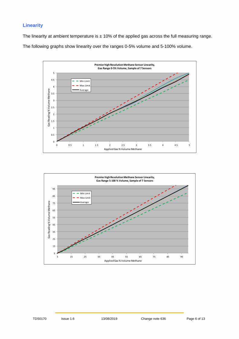
Power supply considerations
The sensor power supply rise time must be less than 50 mS to ensure correct operation. Operation outside the range of 3 – 5 V dc will result in either fault indication, or the sensor will not function correctly. The current consumption varies during the program cycle as shown below. The peak current is around 34mA whilst the infrared source is powered, falling to around 20mA, and the current whilst the source is turned off is around 4mA. The net average current with a 3V power supply is 8mA. The average power consumption is 24mW.
Sensor over-range condition
The sensor will continue to provide an output up to a pre-determined percentage of the full scale value; at this point the reading is clamped, regardless of any further increase in detected gas level. The over-range value should be specified when ordering; choose from the following values 100%, 125%, 150% and 200% The linearity of the output is only guaranteed up to the full scale for the sensor; the over-range condition for the host instrument should therefore be determined by the user.
Current waveform for Premier Low Power 2 sensor
4 mA
20mA Current peak 34 mA

TDS0170 Issue 1.6 13/08/2019 Change note 636 Page 9 of 13
Sensor fault indication
The sensor constantly performs checks on the internal memory contents, the incoming supply voltage and the analogue signal values. These checks are used to ensure that the sensor is operating within its correct parameters, and that no internal faults have developed. If a fault condition is detected:
1) the output will be set to 0V. 2) The output value that is read when using the communications pins, instead of the voltage
output pin, will be set to -250% full-scale.
As mentioned in the “Sensor warm-up time” section above, the voltage at the output pin during the warm-up time can be specified when ordering sensors.
Digital interface The digital communication pins “RX” and “TX” operate at a 2.8V logic level. When interfacing to external circuitry that uses a higher voltage level it is necessary to limit the current that can flow. The external voltage level should be 5V maximum and a 3K3 resistor should be used in series with each communication pin. The Rx and Tx voltage limits are as follows: RX - VIH: Input ‘High’ minimum voltage - 0.8 VDD = 2.24V RX - VIL: Input ‘Low’ maximum voltage - 0.2 VDD = 0.56V TX - VOH: Output ‘High’ minimum voltage - VDD - 0.7 = 2.1 TX - VOL: Output ‘Low’ maximum voltage - 0.6V
Refer to tds0045 Communication Protocol for further details. Contact Dynament Ltd. to obtain the document.

TDS0170 Issue 1.6 13/08/2019 Change note 636 Page 10 of 13
SPECIFICATION @ 20C (68F) ambient temperature
Operating Voltage Range: 3.0 – 5.0 V d.c.
Operating Current: Average current 8mA. See diagram on page 8
Programmable Output Voltage Ranges: 0.1V to 2.5V d.c.
Methane measuring range: 0-5%, 0-100% volume, or both
Propane measuring range: 0-2% volume
Resolution: 0.01% for readings up to 5% volume methane 0.1% for readings from 5% up to 100% volume methane 0.01% propane for all readings
Linearity: The output is linear within ± 10% of the applied gas, or
+/-0.05% volume, whichever is greater.
Warm up time: To final zero ± 2% full-scale: approximately 1 minute, some sensors may take longer.
Accuracy: 10% of the applied gas @ 20C (68F), 1 bar pressure.
Pressure 5% of the calibration pressure to maintain the accuracy limits
Methane response Time T50: <10s
Methane response Time T90: <30s
Propane response Time T50: <10s
Propane response Time T90: <30s
Zero Repeatability: 0.05% volume methane
Span Repeatability: 0.1% volume methane at 5% applied gas.
2% volume methane at 100% applied gas.
Long term zero drift: 0.05% volume methane per month
Operating temperature range: -20C to +50C (-4F to 122F)
Temperature performance over the range
-20C to +50C(-4F to 122F): * May not be applicable when using gas cross-reference factors
± 0.1% volume or ± 10% of applied gas up to 50% of full
scale, 15% of applied gas from 50% to 100% of full scale, or 2% of full scale whichever is greater over the range.
Storage temperature range: -20C to +50C (-4F to 122F)
Humidity range: 0 to 95% RH non-condensing.
Digital signal format: 8 data bits, 1 stop bit, no parity. 2.8V logic level
Standard baud rates: 38,400, 19,200, 9600, 4800
User configurable parameters and functions:
Zero output voltage Full-scale output voltage Sensor ‘zero’ function Sensor ‘span’ function Over-range value
MTBF: > 5 years
Weight : 15 grams

TDS0170 Issue 1.6 13/08/2019 Change note 636 Page 11 of 13
CERTIFICATION DETAILS
European ATEX Certification
Sensor types MSH2-LP2
Sensor types MSH2ia-LP2
Approval body FTZU FTZU
Certificate Number FTZU 14 ATEX 0213U
(See footnote 2) FTZU 14 ATEX 0213U
(See footnote 2)
Test Standards
EN 60079-0:2012 + A11:2013 EN 60079-1:2014 EN 60079-11:2012
EN 60079-0:2012 + A11:2013 EN 60079-1:2014 EN 60079-11:2012
EN 50303:2000
Certification Codes I M2 Ex db I Mb
II 2 G Ex db IIC Gb I M1 Ex db ia I Ma II 2 G Ex db IIC Gb
Input parameters 0.8W max, 30V max.
(See footnote) Ui=6V dc, Pi=0.8W
(See footnote)
Operating temperature -20°C to +60°C (See footnote 1)
International IECEx Certification
Sensor types MSH2-LP2
Sensor types MSH2ia-LP2
Approval body FTZU FTZU
Certificate Number IECEx FTZU 15.0002U
(See footnote 2) IECEx FTZU 15.0002U
(See footnote 2)
Test Standards IEC60079-0:2011, Edition 6
IEC60079-1:2014-06, Edition 7
IEC60079-0:2011, Edition 6 IEC60079-1:2014-06, Edition 7
IEC60079-11:2011, Edition 6
Certification Codes Ex db I Mb, Ex db IIC Gb Ex db ia I Ma, Ex db IIC Gb
Input parameters 0.8W max, 30V max. Ui=6V dc, Pi=0.8W
Operating temperature -20°C to +60°C (See footnote 1)
North American Certification Sensor type MSH2-LP2 Sensor type MSH2ia-LP2
Approval body Underwriters Laboratory Inc. Underwriters Laboratory Inc.
File Reference E336365 E336365
Test Standards
UL 60079 – 0, 4th Edition UL 60079 - 1, 6th Edition
CAN/CSA-C22.2 No. 60079-0-1-7 CAN/CSA-C22.2 No. 60079-1
part 1, 1st Edition
UL913 7th, Edition UL 60079 – 0, 4th, Edition
UL 60079 – 11, 2nd , Edition CAN/CSA-C22.2 No. 157-92
Hazardous Locations
Class 1, Zone 1, AEx d IIC and Ex d IIC
Hazardous Locations
Class I, II, III, Division 1
Class 1, Zone 0, AEx ia IIC, T4 with 60°C ambient
Input/Entity parameters 0.8W max, 30V max. Ui=6V dc, Pi=0.8W,
Ci=4.105µF, Li=0 mH
Note1 Input parameters are defined for certification purposes only, refer to the “Specification” table for the sensor operating voltage and temperature range.

TDS0170 Issue 1.6 13/08/2019 Change note 636 Page 12 of 13
Warranty information All Dynament Premier sensors carry a five-year warranty against defects in materials and workmanship. The warranty is invalidated if the sensors are used under conditions other than those specified in this data sheet. Particular attention should be paid to the following criteria:
• Observe the correct supply polarity
• Do not exceed the maximum rated supply voltage of 5V
• Do not solder directly to the sensor pins
• Do not expose the sensor to corrosive gases such as hydrogen sulphide
• Do not allow condensation to take place within the sensor
Dynament reserve the right to alter technical specifications, without prior notice, when it is appropriate to implement a technical enhancement that leads to improved performance. Should any changes be required that could affect the customer’s use of the product, Dynament will endeavour to contact customers directly to inform them of the changes.
- ve supply + ve
supply
20
16.6 -0/+0.2
4.24
All dimensions are in millimetres. Pins viewed from underside Diameter of pins = 1.5 +/- 0.05 Tx & Rx communication connections are available as either pads or pins
5.08
0.43
Tx
Rx
Dia 20mm
Dia. 15mm
MECHANICAL DETAIL
1. TOLERANCE: +/- 0.15 UNLESS OTHERWISE STATED.
2. RECOMMENDED PCB SOCKET WEARNES CAMBION LTD CODE: 450-3326-01-06-00.
3. USE ANTI-STATIC PRECAUTIONS WHEN HANDLING
4. DO NOT CUT PINS
5. DO NOT SOLDER DIRECTLY TO PINS 6. THE LABELLING ADDS UP TO 0.2 TO THE OUTER DIAMETER, AND UP TO 0.2 TO THE OVERALL HEIGHT
NOTES
10.67
4.8 ±0.5 7.62
Output Signal

TDS0170 Issue 1.6 13/08/2019 Change note 636 Page 13 of 13
Ordering Details
In order to completely specify the type of sensor that is required, the customer needs to provide the following information:-
• An Order Code (see below) that specifies the sensors’ basic physical and electrical characteristics.
• The sensor configuration requirements.
CONFIGURATION OPTIONS (To be stated on customer order in addition to the Order Code)
1. Output voltage for zero. 2. Output voltage for span. 3. Sensitivity e.g. 0.4 – 2.4V = 5% volume CO2 4. Communication speed – 38,400 baud (default), specify alternative rate if required. 5. Over-range value: 100%, 125%, 150% and 200% of full-scale value.
EXAMPLE OF ORDER CODES
MSH2 – LP2 / HC / 3 / V / P / F
Option FILTER : BLANK = OMITTED
F = FITTED
SUPPLY POLARITY : P = Positive
OUTPUT TYPE : V = Voltage
NUMBER OF PINS : 3, 4 or 5 SENSOR TYPE : HC LOW POWER 2
TYPE MSH2 or MSH2ia (For Mining M1 applications only)