Embed Size (px)
Citation preview

1, NASA 1 1 1 Technical ~' Paper
I
I"
-_ - ' I
\ NASA
Low-Speed Stability and Control igation of Blowing on-
>Fi%ter: Flight Characteristic >at High Angles of Attack
c \
https://ntrs.nasa.gov/search.jsp?R=19850015397 2018-07-22T10:03:51+00:00Z

NASA Tech n ica I Paper 2431
1985
National Aeronautics and Space Administration
Scientific and Technical Information Branch
Low-Speed Stability and Control Wind-Tunnel Investigation of Effects of Spanwise Blowing on Fighter Flight Characteristics at High Angles of Attack
Dale R. Satran, William P. Gilbert, and Ernie L. Anglin Langley Research Center Hampton, Virginia
Summary The Langley Research Center has recently con-
ducted an investigation to determine the effects of spanwise blowing on two configurations representa- tive of current fighter airplanes. The two config- urations differed only in wing planform, with one incorporating a trapezoidal wing and the other a 60" delta wing. This research emphasized deter- mining the lateral-directional characteristics, partic- ularly in the stall/departure angle-of-attack range; however, the effects of spanwise blowing on the lon- gitudinal aerodynamics were also determined. The wind-tunnel tests included measurement of static force and forced-oscillation aerodynamic data, visu- alization of the airflow changes created by the span- wise blowing, and free-flight model tests. The effects of blowing rate, chordwise location of the blowing ports, asymmetric blowing, and blowing on the con- ventional aerodynamic control characteristics were investigated.
Spanwise blowing provided significant lift aug- mentation with little effect on the pitch trim re- quirements. The lift augmentation showed very lit- tle dependence on the longitudinal port location, but showed a large dependency on the leading-edge sweep angle of the wing planform. The maximum influence of spanwise blowing occurred in the angle-of-attack range from 20" to 25" for the moderately swept trape- zoidal wing and in the angle-of-attack range from 30" to 35" for the highly swept delta wing.
The influence of spanwise blowing on the lateral- directional characteristics was found to be signifi- cantly dependent on the port location, blowing rate, and wing planform. The proper selection of port lo- cation and blowing rate provided significant improve- ments in the lateral-directional stability and control characteristics. In addition, spanwise blowing on the trapezoidal wing produced a large improvement in the roll damping in the angle-of-attack range from 15" to 30". The free-flight tests confirmed the benefi- cial effects of spanwise blowing measured in the static force and dynamic force tests. The dynamic lateral- directional flight characteristics were much improved with spanwise blowing because of increased damping and lateral control effectiveness.
Introduction Superior fighter airplane maneuverability requires
providing airplanes with high lift at reasonable values of the lift-to-drag ratio (L ID) . Increasing the air- plane angle of attack to obtain higher lift-coefficient (CL) values eventually produces massive airflow sep- aration on the wing accompanied by a rapid increase in drag and loss of LID. Several methods have been
studied to eliminate this separation, such as wing sweep, flaps, or blowing. This flow separation oc- curs in a relatively organized fashion on highly swept wings (with sweeps greater than 50' to 60") on which a strong leading-edge vortex is formed, and the air- flow then reattaches to the wing upper surface behind this vortex to provide the now well-known vortex lift (refs. 1 to 3). Fighter wings of lower sweep (30" to 50") generally do not sustain such a strong leading- edge vortex naturally because of early vortex burst and, therefore, do not obtain vortex lift benefits.
However, in recent years several powered lift aug- mentation concepts have been developed such as vec- tored thrust (refs. 4 to 6), vectored engine over wing (refs. 7 to 9), and spanwise blowing (refs. 7 to 16). The concept called spanwise blowing produces possi- ble aerodynamic performance benefits by blowing a small high-velocity air jet from the wing root (near 25-percent chord) in a spanwise direction over the wing upper surface parallel to the upper surface and the wing leading edge. This jet apparently enhances the strength of the leading-edge vortex and promotes flow reattachment aft of the vortex, thus providing vortex-lift benefits (refs. 14 to 16).
Although extensive performance testing has been conducted with the spanwise-blowing concept, much less testing and analysis work has been done to understand the impact on aerodynamic stability and control characteristics. Since experience has shown that deficiencies in stability and control can limit usable lift, it is imperative that the impact of new concepts on stability and control be evaluated.
The present investigation was therefore conducted to study the impact of spanwise blowing on the low-speed, high-angle-of-attack stability and control characteristics of a current fighter configuration; an- gles of attack through maximum lift are included. The approach was to equip a current fighter design with spanwise blowing, obtain an increase in CL by blowing, and then investigate the blowing impact on stability and control. A trapezoidal planform of mod- erate sweep (34") was subjected to the most exten- sive testing, although a delta wing with relatively high sweep (60") was included in the study to under- stand dependence on wing sweep. The wind-tunnel investigation included conventional static force tests, forced-oscillation dynamic tests, and free-flight tests of a tethered dynamically scaled model. In addition, flow-visualization tests were included to help under- stand the influence of spanwise blowing on the stalled flow field about the model.
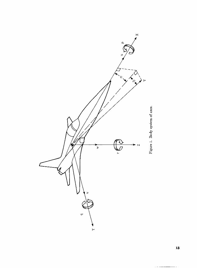
Symbols The longitudinal forces and moments are re-
ferred to the stability axis system, and the lateral-

I directional data are referred to the body axis sys- tem. (See fig. 1.) All aerodynamic data are referred to a moment reference center located longitudinally at 18 percent of the mean aerodynamic chord of the wing of each configuration. Aerodynamic forces and moments are reduced to coefficient form on the ba- sis of the geometric characteristics of each configu- ration. Dimensional quantities have been presented both in the International System of Units (SI) and in the U.S. Customary Units. Measurements and cal- culations were made in the U.S. Customary Units. Conversion factors for the two systems are found in reference 17.
b wing span, m (ft)
CD drag coefficient, FD/qS
CL lift coefficient, FL/qS
ACL incremental lift coefficient (blowing on I minus blowing off)
Cl rolling-moment coefficient, Mx/qSb
ACl incremental rolling-moment coefficient (control deflected minus control undeflected)
Crn pitching-moment coefficient, My/qSC
c n yawing-moment coefficient) Mz/qSb
Acn incremental yawing-moment coefficient (control deflected minus control undeflected)
I CT spanwise-blowing thrust coefficient, FT/QS
CY side-force coefficient, Fy /qS
A C y incremental side-force coefficient (control deflected minus control undeflected)
mean aerodynamic chord, m (ft) - C
FA axial force, N (lb)
FD drag force, N (lb)
FL lift force, N (lb)
FT thrust for spanwise blowing parallel to I wing leading edge, FA/ sin A , N (lb)
FY side force, N (lb)
f frequency, Hz
I X moment of inertia about X body axis, kg-m2 (slug-ft2)
IY moment of inertia about Y body axis, kg-m2 (slug-ft2)
Iz moment of inertia about Z body axis, kg-m2 (slug-ft2)
k reduced-frequency parameter, wb/2V
LID lift-to-drag ratio, CL/CD MX rolling moment, m-N (ft-lb)
MY pitching moment, m-N (ft-lb)
Mz yawing moment, m-N (ft-lb)
P roll rate, rad/sec
9 pitch rate, rad/sec
9 free-stream dynamic pressure,
r yaw rate, rad/sec
S wing area, m2 (ft2)
u, v, w
Pa (lb/ft2)
components of resultant free-stream velocity V along X , Y, and Z body axes, respectively
V free-stream velocity, m/sec (ft/sec)
X , Y , 2 2 longitudinal distance from junction
body reference axes
of wing leading edge and fuselage to spanwise-blowing port, m (ft)
a angle of attack, deg
P angle of sideslip, deg
P 6,
6f,LE leading-edge flap deflection, deg
6 h horizontal-tail deflection, positive for nose-down pitch, deg
6, rudder deflection, positive for nose-left
rate of change of sideslip, rad/sec
aileron deflection (per side), positive for left roll, deg
Yaw, deg sweep angle of wing leading edge, deg
angular frequency, 27r f , rad/sec
A W
2
sin CY Cl, IZ
I X Cnp,dyn = cos CY cnp - -
Abbreviations:
BL body line
FS fuselage station
LCDP lateral control divergence parameter, cn6
c160 Cna - CL
V.T. vertical tail
Description of Model A twin-engine model representative of a current
fighter airplane configuration was used in the present study. The model was tested with trapezoidal and delta wing planforms, Sketches of each configuration are shown in figure 2, and the principal mass and dimensional characteristics for each configuration are listed in table I. The trapezoidal wing with a leading- edge sweep of 34" incorporated a wing leading-edge flap capable of deflecting downward to 25". The delta wing planform with a leading-edge sweep of 60" had the same wing area as the trapezoidal wing, but it incorporated no wing flaps. For both wings, the model incorporated a conventional single center- vertical tail (with rudder) and a conventional all- movable horizontal tail. Both wings were equipped with conventional ailerons for roll control.
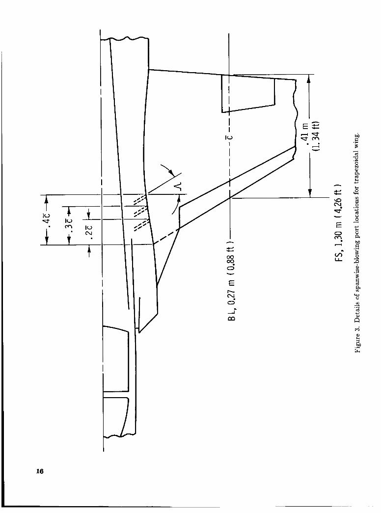
The model fuselage was modified to incorporate a pair of spanwise-blowing ports at each of three lon- gitudinal locations. These forward, middle, and aft port positions were located at distances equal to 20, 30, and 40 percent of the wing mean aerodynamic chord aft of the junction of the wing leading edge with the fuselage side, as shown in figure 3. The an- gle of the blowing ports was oriented to match the leading-edge sweep of the wing being tested. The ports were formed from 0.95-cm (0.375-in.) inside- diameter steel tubing that exited flush with the fuse- lage side 1.17 cm (0.46 in.) above the wing upper surface.
For the free-flight tests, only the trapezoidal wing was tested and it was fitted with only the most aft blowing port locations. During the model flight tests, pitch control was provided by deflection of the all-movable horizontal tail and lateral-directional control was provided by conventional wing-mounted ailerons and a rudder. These control surfaces
were powered by high-performance electropneumatic servoactuators.
Test Techniques and Conditions The tests performed included measurement of
static aerodynamic data, flow visualization of the air- flow over the wing, observation of free-flight model tests, and measurement of forced-oscillation aerody- namic data. The effects of blowing rate, chordwise location of the blowing ports, asymmetric blowing, and blowing on the conventional aerodynamic con- trol characteristics were investigated.
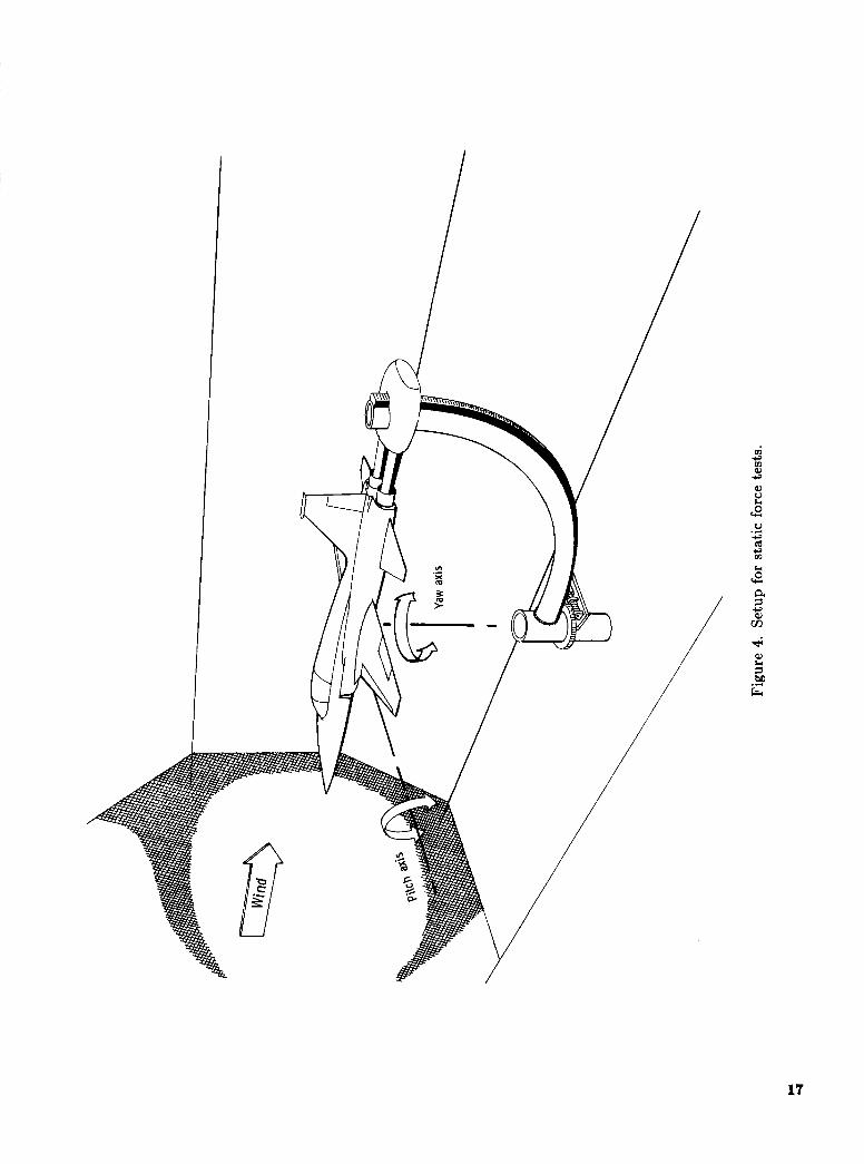
Static Force Tests
The static force tests were conducted in the Lan- gley 12-Foot Low-Speed Tunnel at a dynamic pres- sure of 192 Pa (4 lb/ft2), resulting in a Reynolds number of 0.5 x lo6 based on the mean aerodynamic chord for the trapezoidal wing. The test setup is shown in figure 4. The model was tested through an angle-of-attack range from 0" to 55" at sideslip angles of -5", 0", and 5". The three longitudinal locations for the spanwise-blowing ports were each tested separately for the trapezoidal and delta wings to determine the most effective port location for the remainder of the tests for each individual wing. On the trapezoidal wing, the effects of the leading-edge flaps, the vertical tail, the pitch, yaw, and roll con- trol characteristics, and asymmetric spanwise blow- ing were tested. These tests were conducted with spanwise-blowing thrust coefficients CT of 0.04, 0.08, and 0.12.
The thrust outputs for the spanwise-blowing ports were balanced to prevent any force or moment loads, except for an xxial force aloog the X - a i s of the model. The axial force was removed by rezero- ing the data acquisition system, and therefore the aerodynamic data presented herein for these tests reflect only the aerodynamic induced effects of the blowing. The thrust coefficient was computed as CT = "/;E A and included the total blowing for both ports.
Forced-Oscillation Tests
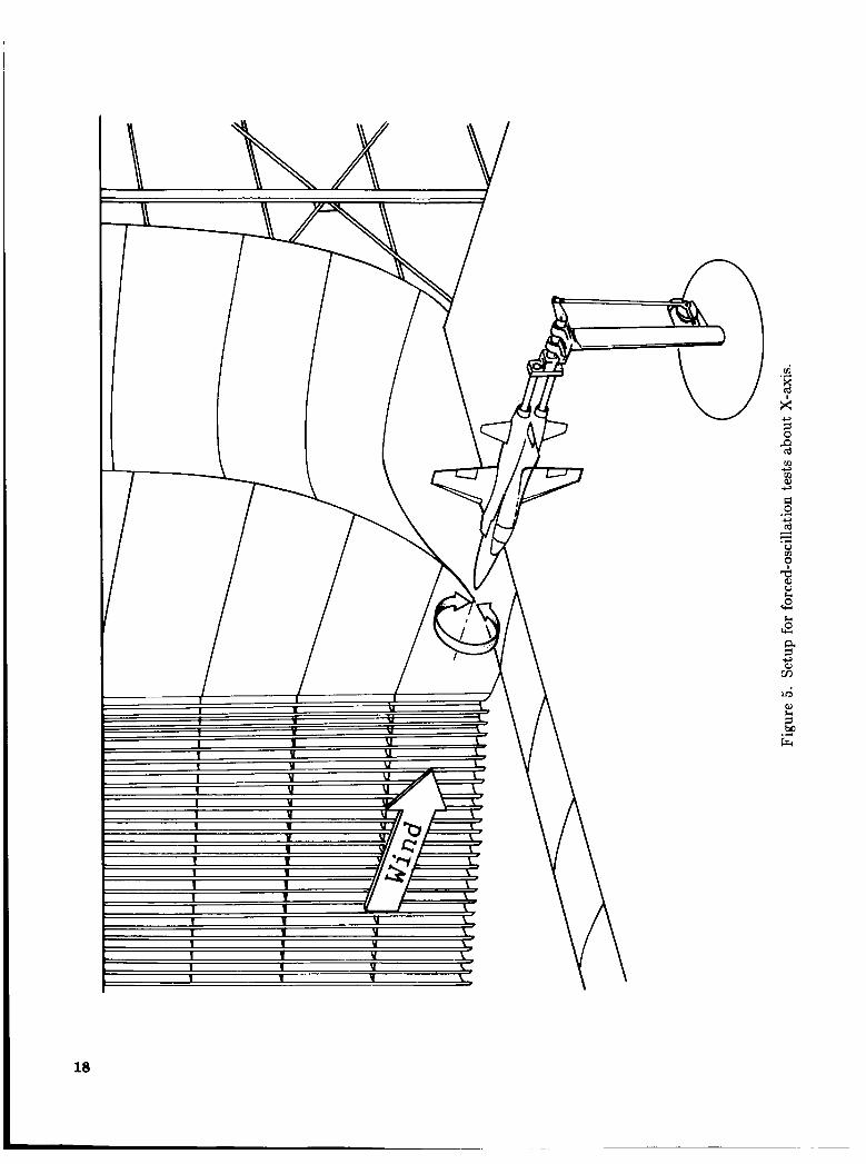
Roll damping measurements were made in the Langley 30- by 60-Foot Tunnel on only the trape- zoidal wing with and without spanwise blowing. For the test setup illustrated in figure 5, the forced- oscillation test technique described in reference 18 was used. Forced-oscillation tests were conducted extensively on this model in a previous investigation, as described in reference 19. Since this information was available, the test conditions were limited. The
3

roll damping tests were conducted tor only the aft port location at CT = 0.08, for a dynamic pressure of 383 Pa (8 lb/ft2), and for an angle-of-attack range from 0" to 50". The tests were conducted for one oscillation amplitude, -5" to 5", and for one oscilla- tion frequency, 0.48 Hz, which results in a reduced- frequency parameter k of 0.08.
Flow-Visualization Tests Flow-visualization tests were performed during
the static tests by using a helium-bubble technique. A helium-bubble generator system formed streams of neutrally buoyant bubbles by blowing a helium-air mixture through a soap film inside a nozzle and then using a separate air line to blow the bubbles out of the nozzle, where tunnel airflow carried them down- stream. With the tunnel lights off and the model painted black to reduce glare, the bubble streams were illuminated by a narrow beam of high-intensity light from a xenon-arc lamp. The bubbles traced the streamlines of the flow over the model, and these flow patterns were recorded on a video tape system. Since the helium bubbles tended to burst at higher dynamic pressures, and the pressure regulation sys- tem could not accurately control the pressures neces- sary for low thrust coefficients a t low dynamic pres- sures, the spanwise-blowing thrust coefficient was re- stricted to the highest level. The flow-visualization tests were conducted at a dynamic pressure of 24 Pa (0.5 lb/ft2) for only the trapezoidal wing. The aft- port location was used for the spanwise-blowing tests a t CT = 0.12.
Free-Flight Tests The dynamic stability and control characteristics
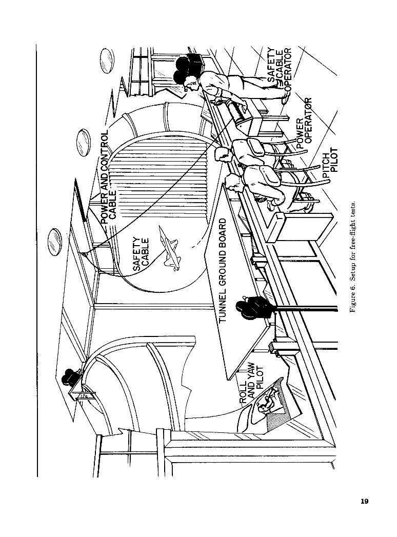
of the model at angles of attack up to and includ- ing the stall/departure region were evaluated by us- ing the free-flight model technique shown schemat- ically in figure 6 and described in reference 20. In such tests, powered, instrumented, dynamically scaled models are flown by remote control in level flight through stall to investigate stability and con- trol characteristics and to identify any tendencies of models to depart from controlled flight. Since the publication of reference 20, the free-flight model con- trol system has been upgraded and, as shown in figure 7, the system now includes high-performance electropneumatic, proportional control-surface ser- voactuators and a minicomputer for simulating the flight control system. The minicomputer, which op- erates in a real-time mode during the flight tests, used, for this investigation, only body-axis angular rate feedbacks to provide artificial damping about the roll, pitch, and yaw axes. Photographs of the
basic configuration during free-flight tests are shown in figure 8. Test results are typically in the form of pilot comments, movies, and time histories of flight motion variables.
For the free-flight tests, model thrust is supplied by compressed air through flexible air hoses in an umbilical cable. (See ref. 14 for more details.) For the spanwise-blowing free-flight tests, compressed air was supplied in a similar manner, with separate air lines for left and right blowing ports. The spanwise- blowing air supply lines were completely independent of the compressed air for thrust. The thrust level for the blowing ports was calibrated prior to the flight by mounting the model to an external strain- gauge balance. The air pressure versus axial-force calibration was used to set the spanwise-blowing levels for the free-flight tests. Asymmetric spanwise blowing was not investigated in the flight tests. The symmetric blowing rate was not changed during a flight since it was impossible to change the blowing rate and keep the left and right ports balanced during the change. As a result, the effective blowing CT increased during a flight since the dynamic pressure decreased as the flight progressed to higher angles of attack and lift coefficients. The preflight thrust was set to give a desired CT value only for a specific angle of attack of interest for that particular flight. The free-flight tests were otherwise carried out by using standard procedures, as described in reference 20.
The free-flight tests were conducted in the Lan- gley 30- by 60-Foot Wind Tunnel. The dynamic pressures ranged from 431 Pa (9 lb/ft2) to 192 Pa (4 lb/ft2), depending upon the lift coefficient of the configuration. Over these test conditions, the spanwise-blowing thrust coefficient varied from 0.02 to 0.45. For the free-flight tests, only the trapezoidal wing was tested and the aft port location was used for the spanwise blowing.
Results and Discussion of Force Tests The results of the static force tests, the flow-
visualization tests, and the forced-oscillation tests are discussed in the following sections. For this investi- gation the moderately swept trapezoidal wing was subjected to the most extensive testing, whereas the delta wing was used only in the static force tests. No corrections were made to the present data since a comparison with data of reference 19 showed good correlation. Static force tests were conducted on both planforms with each of three spanwise-blowing locations. A single blowing port location for the trapezoidal wing was chosen for the remainder of the study, which included leading-edge flap and con- trol effects, flow visualization, aerodynamic damping data, and free-flight tests.
4

Static Longitudinal Characteristics
Static longitudinal characteristics are presented for both the trapezoidal and delta wing planforms showing the effects of blowing rate. Longitudinal characteristics were found to be insensitive to port location for the range of positions studied. The aft port location was chosen for the remaining tests since it provided the best lateral-directional stability characteristics. By using the aft port location, results are presented for the trapezoidal wing to show the effects of blowing rate and to show the effect of spanwise blowing on leading-edge flap effectiveness and control effectiveness.
Trapezoidal wing. The static longitudinal char- acteristics for the trapezoidal wing are presented in figure 9 for the aft port location for several blowing levels. All data presented for the trapezoidal wing are for zero leading-edge flap deflection unless other- wise noted. The effect of spanwise blowing was pri- marily evident in the lift coefficient for angles of at- tack greater than 10" and reached a maximum in the angle-of-attack range from 15" to 25" when spanwise blowing provided nearly 15-percent and 35-percent increases in CL for values of CT of 0.04 and 0.12, re- spectively. As maximum lift was approached, vortex breakdown progressed over the wing and the effect of spanwise blowing decreased.
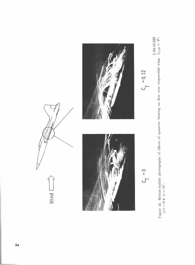
In figure 10 the results of helium-bubble flow- visualization studies show the effect of spanwise blowing on the trapezoidal wing at an angle of at- tack of 15". Flow visualization in the angle-of-attack range from 15" to 25" has confirmed that spanwise blowing produced flow reattachment behind the vor- tex. With the spanwise blowing off, the flow has sep- arated and produced reversed and unattached flow river the wing, as can be seen in the figure. With the spanwise blowing at a thrust coefficient of 0.12, the flow is very steady and shows reattachment to the upper surface of the wing. For this investigation, the leading-edge vortex itself was not generally illu- minated by the helium-bubble technique because of a lack of bubbles entering the core of the vortex, al- though the vortex was observed occasionally but was never recorded on video tape.
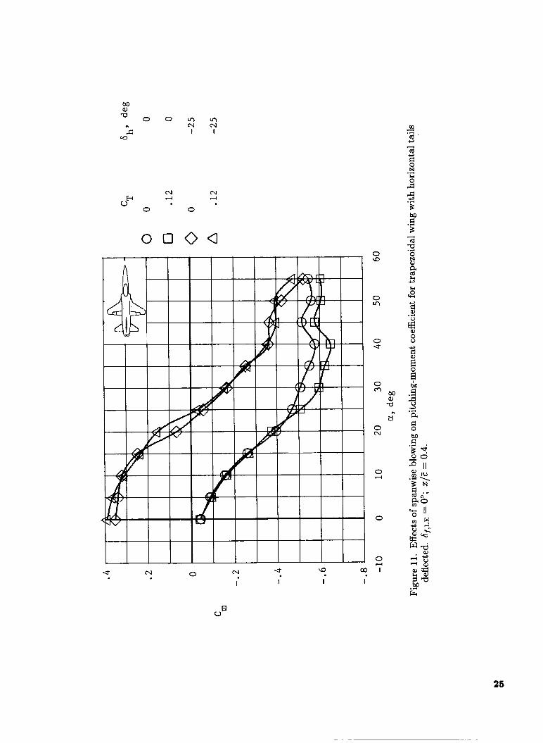
The effects of spanwise blowing on the pitch sta- bility and control of the trapezoidal wing are shown in figure 11. These results show little effect of blow- ing on stability or on pitch trim capability. Unlike most powered-lift concepts, spanwise blowing for this investigation produces a lift increase near the aerody- namic center of the wing and does not therefore pro- duce large pitching moments that would have to be trimmed. Similar results were noted in reference 12.
To evaluate the efficiency of using spanwise blow- ing for lift augmentation, the ratio of lift augmen- tation ACL to thrust coefficient CT was computed. The lift augmentation ratio AcL/cT indicates how efficiently spanwise blowing increases the lift of the wing compared with simply vectoring the blowing with the same CT in the direction of lift for vec- tored thrust. As presented in figure 12, the blowing effectiveness is greatest at an angle of attack of 20" and spanwise blowing is more effective than vectored thrust in creating lift (AcL/cT > 1.0) at angles of attack from 10" up to about 45". In the angle-of- attack range from 15" to 25"; the lift augmentation ratio is at a peak and decreases for the higher blow- ing rates. This indicates that the leading-edge vortex is established by the lower blowing rate, and further increases in blowing rate cause only moderate en- hancements of the vortex flow.
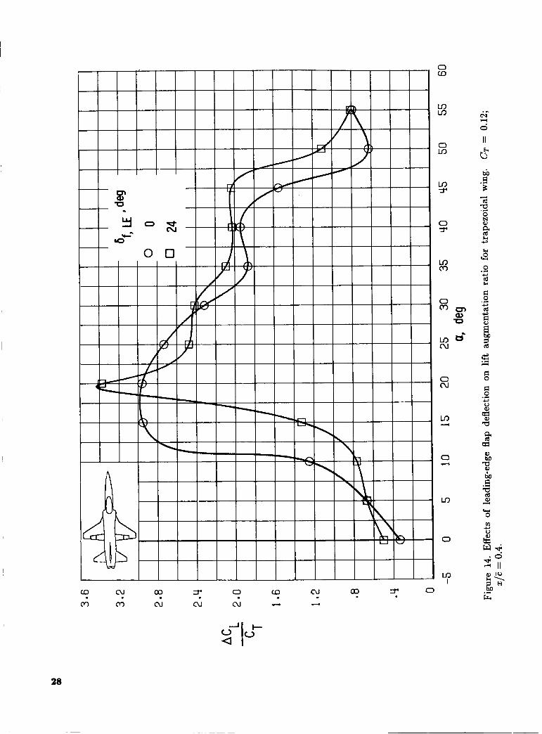
The effects of the leading-edge flap on the trape- zoidal wing are shown in figure 13. The increases in lift due to spanwise blowing with and without the leading-edge flap deflected are seen to be compara- ble. The lift augmentation ratio in figure 14 is gener- ally similar for the flaps-extended and flaps-retracted conditions, although the improvement in the lift aug- mentation ratio occurs approximately 5" earlier with the leading-edge flap retracted rather than deflected. Since deflecting the leading-edge flap delays the flow separation on the wing, the leading-edge vortex may not be established by spanwise blowing until the model is at higher angles of attack.
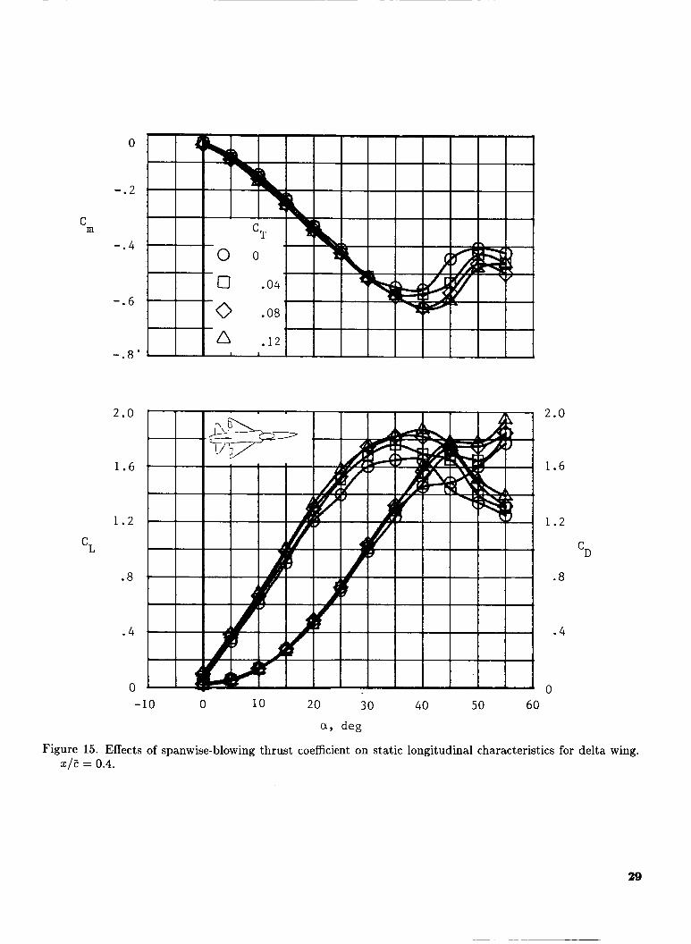
Delta wing. The effects of blowing rate on the delta wing planform are presented in figure 15 for the aft port location. Very little result of blowing is evident, except for a small increase in lift above an angle of attack of 20". Above (Y = 20" the natu- rally formed leading-edge vortex, which is evident for wings of this sweep, is apparently beginning to break down and the spanwise blowing delays this break- down. As in the case of the trapezoidal wing, span- wise blowing did not change the static longitudinal stability for the delta wing planform.
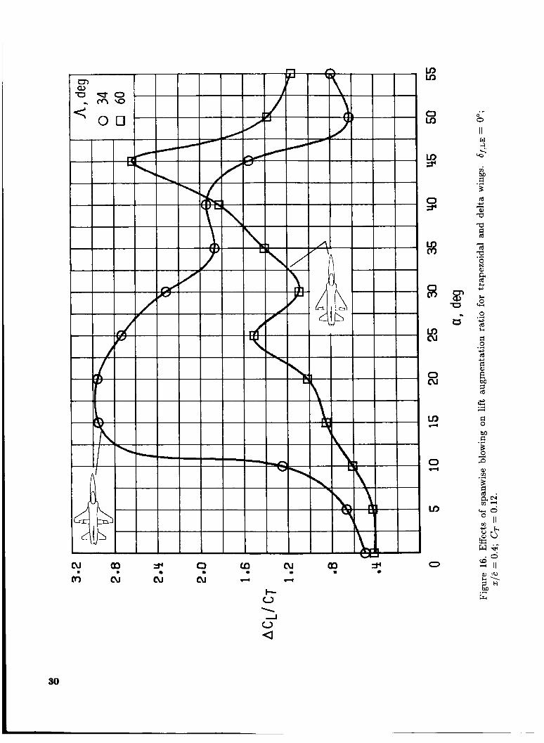
The lift augmentation ratio for the delta wing compared with that for the trapezoidal wing is pre- sented in figure 16 for CT = 0.12. Comparison of the two configurations shows that the lift augmentation ratio for the delta wing remains well below that for the trapezoidal wing in the angle-of-attack range be- low maximum lift. These results show clearly that spanwise blowing can be applied with much greater effectiveness to wings that are not swept high enough to have a stabilized leading-edge vortex.
5
Static Lateral-Directional Characteristics
Static lateral-directional characteristics are pre- sented in terms of the static stability derivatives Cyo, Cna, and Clp. The values of these derivatives were determined for p = -5" and 5". Effects of spanwise blowing on the lateral-directional charac- teristics for both the trapezoidal and delta wing plan- forms are presented with the effects of port locations and spanwise-blowing rates. For the trapezoidal wing only, the effects of spanwise blowing on the vertical- tail effectiveness, aileron and rudder effectiveness, and asymmetric spanwise blowing are presented.
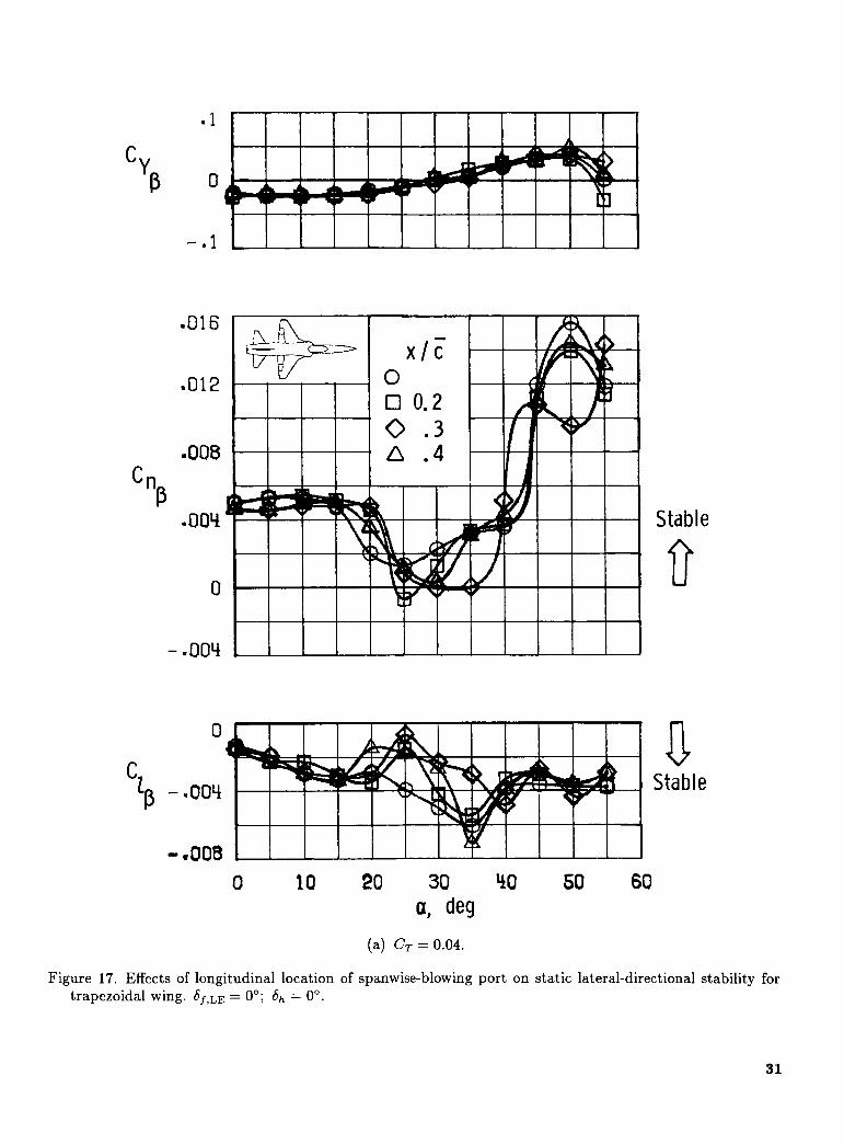
Trapezoidal wing. The effects of spanwise-blowing thrust coefficient and port location on the static lateral-directional stability are shown in figure 17. As expected, the effects occurred primarily over the angle-of-attack range from 15" to 35" where span- wise blowing showed the largest result longitudinally. According to both blowing rates shown, the aft port location provided the highest level of stability, partic- ularly at CT = 0.12. Therefore, the aft port location was chosen for the bulk of the remaining tests.
The effects of the three blowing rates from the aft port on the lateral-directional characteristics are shown in figure 18. For both Cnp and Cia, the highest level of stability with spanwise blowing is evident for the highest blowing rate. The largest effects of blow- ing were evident in the angle-of-attack range from 15" to 35". The level of stability for the trapezoidal wing is strongly dependent on angle of attack. Im- provements in Cnp were obtained below a = 25" for all blowing rates, whereas at higher a only the higher levels of blowing were beneficial. The effects of blow- ing on Cla were generally adverse for the trapezoidal wing, except for C, = 0.12 when the effects were relatively small. The parameter Cna,dyn is useful for summarizing the foregoing results. (See ref. 21.) Pos- itive values of Cnp,dyn indicate departure resistance, whereas near-zero values and negative values indi- cate susceptibility to departures and loss of control. Figure 19 presents Cna,d,,n for the trapezoidal wing for three blowing rates. The highest level of blow- ing provides consistently either no effect or improved stability. The effect of lower blowing rates is slightly adverse below a = 30" and proverse above a = 30". Near a = 30°, there is little or no net effect of span- wise blowing evident.
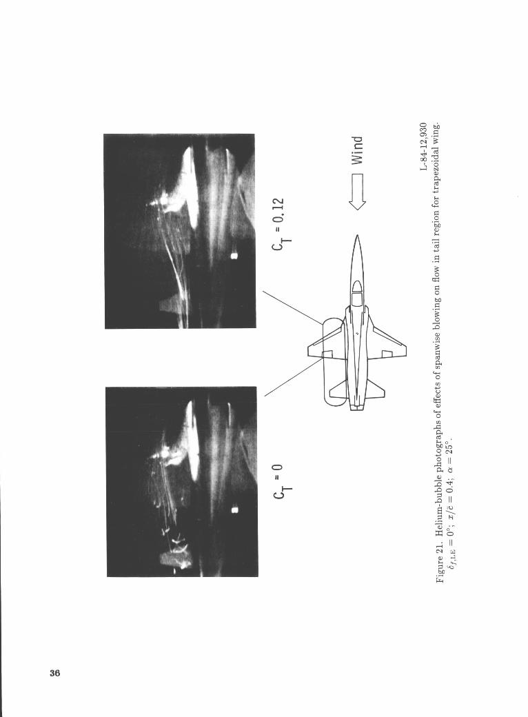
Additional tests were made to evaluate the influ- ence of spanwise blowing on the vertical-tail effective- ness, and the results are presented in figure 20. By referring to the C,,,, results, it is seen that blowing increased the vertical-tail effectiveness in the angle- of-attack range from 15" to about 30". The helium-
bubble flow visualization of the flow over the trape- zoidal wing and horizontal-tail region is shown in fig- ure 21. The flow without spanwise blowing was dis- organized, whereas the flow with spanwise blowing appeared to be stronger and more organized. De- creases in vertical-tail effectiveness occur as a result of either decreased dynamic pressure or an adverse sidewash flow field in the tail region. As noted later in the discussion of the rudder effectiveness, span- wise blowing improved the rudder effectiveness, a re- sult which indicates that the dynamic pressure was increased in the tail region with spanwise blowing. Therefore, it appears that an increase in dynamic pressure provided a portion of the improved vertical- tail effectiveness shown in figure 20.
In summarizing the influence of spanwise blowing on the lateral-directional stability characteristics of the trapezoidal wing, it is important to note that both the longitudinal port location and the blowing rate can have an effect and should be considered in the design process. Furthermore, the influence of spanwise blowing on lateral-directional stability is strongly dependent on the angle of attack a t low to moderate levels of blowing.
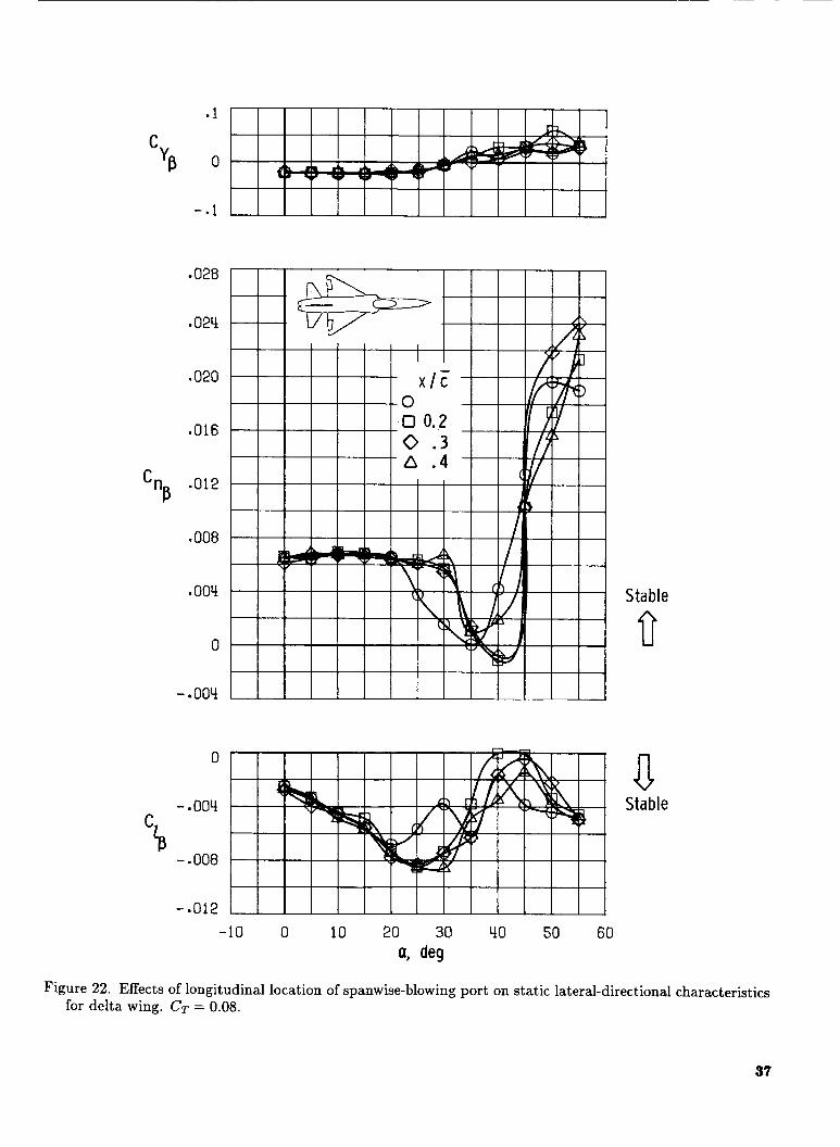
Delta wing. The lateral-directional characteris- tics for the delta wing as a function of port loca- tion and spanwise-blowing thrust coefficients are pre- sented in figures 22 and 23, respectively. As shown in figure 22, the port location had little effect; however, for the small changes observed, the aft port location appeared to produce the highest directional stabil- ity for angles of attack below 35". As shown in fig- ure 23, the blowing rate did have a noticeable effect on both Cna and Cla by producing significant stabi- lizing changes at angles of attack from 20" to 35". Apparently, the natural leading-edge vortex break- down is substantially delayed by spanwise blowing, thereby keeping the dynamic pressure up at the ver- tical tail as well as delaying the asymmetric vortex breakdown at /3 = 0") an effect which degrades the lateral stability. (See ref. 22.) Both with and with- out spanwise blowing, the curves in figure 23 of Cla plotted against a exhibit the characteristic unstable break in the lateral stability as the vortex breakdown begins to occur over the wing surface. Increased blowing rates delayed the unstable breaks very con- sistently such that the highest rate (CT = 0.12) was able to delay the onset of the unstable break by an angle of attack of 10".
I t is significant to note that the trends in the lateral-directional stability changes due to spanwise blowing were different for the two planforms tested. The differences appear to be largely due to the dif- ference in the character of the basic flow over the
6
wing; as an example, the trapezoidal wing has no well-defined leading-edge vortex at higher angles of attack, even though the delta wing does. Spanwise blowing on the delta wing sustained the leading- edge vortex and delayed its breakdown, whereas the blowing on the trapezoidal wing actually established a vortex and sustained the vortex to higher angles of attack. These results indicate that the lateral- directional spanwise-blowing effects are highly con- figuration dependent.
Lateral-Directional Control Characteristics
The effects of spanwise blowing on the lateral- directional control characteristics were investigated only on the trapezoidal wing. The investigation included the rudder and aileron effectiveness and the effect of asymmetric spanwise blowing. The data are presented in terms of the incremental values of C y , C,, and Cl produced by a right-roll or right- yaw control input.
The effects of spanwise blowing on'the rudder ef- fectiveness for the trapezoidal wing are presented in figure 24. Without spanwise blowing, the rudder ef- fectiveness goes to 0 near an angle of attack of 37". Application of spanwise blowing at CT = 0.12 signifi- cantly increases the rudder effectiveness above an an- gle of attack of 25" to 30". This improvement in rud- der effectiveness with spanwise blowing is attributed to the increased dynamic pressure at the rear of the fuselage, as noted earlier in the discussion for figure 21.
The effects of spanwise blowing on aileron effec- tiveness for the trapezoidal wing are shown in fig- ure 25. Spanwise blowing increased the incremental rolling moment,s up tro an angle of attack of 30". The relatively larger improvement in aileron effectiveness due to blowing in the angle-of-attack range from 10" to 20" may be attributed to the large improvements in flow, such as the reattachment of the flow on the rear portion of the wing as indicated in figure 10. In the angle-of-attack range from 20" to 30", the smaller improvement in the aileron effectiveness may be an indication that the vortex has broken down at the outboard region of the wing where the ailerons are located. Unfortunately, the ailerons produced a no- ticeable adverse yawing moment with spanwise blow- ing that the model did not exhibit without blowing. The influence of spanwise blowing on lateral con- trol characteristics is summarized by using the lat- eral control divergence parameter (LCDP) shown in figure 26. This parameter indicates the susceptibil- ity of the model to a roll reversal for an aileron-alone control input. Negative values indicate roll reversal. Spanwise blowing provided substantial lateral con-
trol improvements between angles of attack of 25" and 40".
The effects of asymmetric spanwise blowing are shown in figure 27. Using asymmetric blowing for roll control provided significant increases in the roll con- trol available at angles of attack from 10" to 40". In this angle-of-attack range, the roll control provided by asymmetric blowing alone (CT = 0.12) is compa- rable to the roll control provided by the ailerons at an angle of attack of 0". The data show that asym- metric spanwise blowing also produced large adverse yawing moments at these angles of attack. Analysis suggests that the large adverse yawing moments are produced by the increase in drag on the blown wing and by an adverse sidewash on the vertical tail. Since the data presented included only the aerodynamic ef- fects for the asymmetric spanwise blowing, the thrust effects on yawing moment should also be taken into account. However, an asymmetric thrust coefficient of 0.12 produces a positive yawing moment of only 0.0075, which is considerably smaller than the ad- verse aerodynamic yawing moments produced. The rudder-control effectiveness data shown in figure 24 indicate that very large rudder deflections (6, > 30") would be needed to balance out the adverse yawing moments of this magnitude. An additional source of yaw control would probably be needed to allow coordinated rolls using asymmetric blowing.
Dynamic Lateral-Directional Stability Derivatives
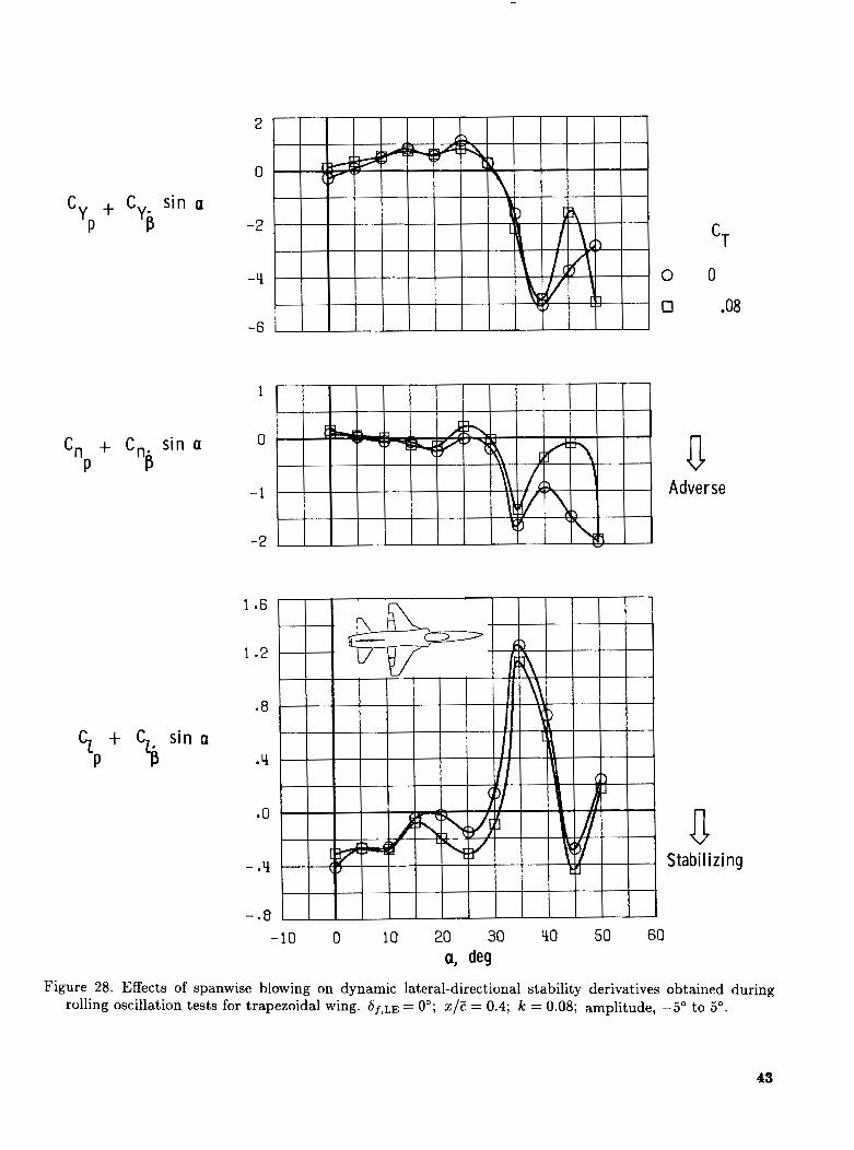
The effects of spanwise blowing on the dynamic lateral-directional stability derivatives were obtained on the trapezoidal wing and only with rolling os- cillation tests. The results of the forced-oscillation tests in roll are presented in figure 28. The most
tively large stable increase in the roll damping deriva- tive, Clp +Cle sin a, that occurs in the angle-of-attack range from 15" to 30". This increase in roll damp- ing is attributed to the enhancement of the leading- edge vortex with spanwise blowing. The increased roll damping due to spanwise blowing is obtained in the same angle-of-attack range in which the lift aug- mentation was greatest. This increased damping is highly desirable for providing a much more stable airplane in the angle-of-attack range when the pilot can take advantage of the increased lift for improved maneuvering performance.
Above an angle of attack of 30" to 35", the roll- damping derivative becomes highly positive (desta- bilizing) and the cross derivative, Cnp + Cng sin a, becomes highly negative (adverse). The effect of spanwise blowing on both of these derivatives was
-:-:C---t AFFn-t 4 v . n tn c-mmr.,;cc. h l n . x r ; m m ;a tho r n l l - U l ~ j l l l l l C . ( L L I b L L I b b " UUL u v o p c & A L . . L . x " I v . . L U 6 I" VU., I b I U
7

in a beneficial direction, but the magnitude of the improvements was so small that the derivatives re- mained highly unstable. As discussed in refer- ence 19, the dynamic lateral-directional derivatives without spanwise blowing obtained during yawing- and rolling-oscillation tests, Cnv - Cna cosa, Clr - Cla cos a, Clp + Clg sin a, and Cn, + Cna sin a, were all highly unstable above an angle of attack of 30" to 35". Component tests showed that the nose was the principal cause of the unstable values of damp- ing. Since spanwise-blowing effects are primarily re- stricted to the wing and tail regions, minimal effects on these unstable derivatives by spanwise blowing would be expected, as shown for the rolling deriva- tives in figure 28.
Results and Discussion of Free-Flight Tests Free-flight tests were conducted only on the trape-
zoidal wing for a leading-edge flap setting of 0" with only the aft port location for spanwise blowing. As noted earlier, the levels of spanwise blowing were set at the beginning of a flight and remained unchanged during the flight. Also, asymmetric spanwise blow- ing was not flight tested. Since the free-flight tests were intended primarily as an investigation of the lateral-directional characteristics of the model, the pitch damper was active for all the tests; and the pitch pilot's task was to fly the model as smoothly as possible and to hold the model in place in the tunnel test section as closely as possible by making proper trim changes and minimizing pitch excursions.
Longitudinal Characteristics Spanwise blowing did not noticeably affect the dy-
namic longitudinal stability and control characteris- tics of the model. With spanwise blowing the model could be flown at higher lift coefficients, as expected from the force test results. It should be noted that no unusual or unsatisfactory characteristics were noted during the tests and the pilot expressed satisfaction with the stability and control characteristics up to the highest angles of attack flown (30" to 35").
Lateral-Directional Characteristics The trapezoidal wing exhibited two lateral-
directional flight problems: a directional divergence and a lightly damped roll oscillation. The effects of spanwise blowing on the directional divergence were generally negligible, whereas the effects on the roll oscillation or "wing rock" were significant, as was in- dicated in the data presented in figure 28.
In the angle-of-attack range from 30" to 35", the model exhibited an uncontrollable yawing motion
that appeared to be a slow directional divergence. The angle of attack at which the apparent directional divergence occurred was not affected by spanwise blowing. The values of Cng,dy, shown in figure 19 did not predict a divergence as observed in the model flight tests. It appears, therefore, that the slow di- rectional divergence exhibited by the model near an angle of attack of 30", as noted in reference 19, is probably associated with the unstable values of yaw and roll damping discussed earlier in this paper and with the low control power illustrated in figures 24 and 25 for the rudder and ailerons, respectively. Nei- ther of these factors is accounted for in the Cng,dyn criterion. The departure motion was apparently not affected by the gains in rudder and/or aileron effec- tiveness due to spanwise blowing because these gains were relatively minor compared with the large un- stable moments generated by the yaw and/or roll damping derivatives. However, the pilot found the model to be easier to fly with spanwise blowing up to the divergence angle of attack because of the in- creased static and dynamic lateral-directional stabil- ity and rudder and aileron control power available at the lower angles of attack.
In the flight tests with the ailerons and rudder interconnected for coordinated controls, the model exhibited a mild wing rock at an angle of attack of 20" without spanwise blowing when the roll and yaw dampers were off. With either spanwise blowing or the roll and yaw dampers on, the model exhibited satisfactory flight characteristics with no appreciable wing rock below an angle of attack of 30". With both spanwise blowing and the dampers on, the flights were much smoother and the piloting effort was greatly reduced. The improved flight characteristics with spanwise blowing are probably associated with the increase in roll damping near a = 20", as shown in figure 28.
In addition to flights with coordinated lateral controls, flights were also made with rudder alone and ailerons alone to investigate some of the lateral- directional stability and control characteristics more thoroughly. The directional control with the rudder alone and roll and yaw dampers on was adequate up to the angle-of-attack range for a divergence with and without spanwise blowing. With both dampers on and without spanwise blowing, the model with rudder along exhibited a severe, although still con- trollable, wing rock a t an angle of attack of 20". For small thrust coefficients (CT < 0.06), the spanwise blowing damped out the wing rock, but large roll os- cillations could result with the rudder alone used for control. For larger thrust coefficients (CT > 0.06), the spanwise blowing with both dampers on pro- duced smooth flights and allowed the lateral pilot
8

to control the model with the rudder alone as easily as with coordinated controls.
In flights of the model with ailerons alone for lateral control, the model was uncontrollable above an angle of attack of 15" without spanwise blowing. With spanwise blowing (CT > 0.04), the model was controllable through an angle of attack of 30" but had a tendency to wander in yaw. This improvement in aileron control with spanwise blowing was evident by the changes in the lateral control divergence parame- ter (LCDP) shown in figure 26. The improved control indicated by LCDP, which is largely due to improved Cna and aileron effectiveness with spanwise blowing, correlated well with the improved control character- istics for the free-flight model with spanwise blowing.
Interpretation of Results The results of the free-flight tests for the trape-
zoidal wing without spanwise blowing are in very good agreement with the characteristics exhibited in reference 19. In particular, below an angle of attack of 30", the absence of any divergence, the large rud- der effectiveness, and the absence of adverse yaw due to ailerons appear to have been adequately produced by the model. Of course, the low values of Mach and Reynolds numbers associated with the present tests could cause some characteristics, such as vor- tex breakdown, to occur at slightly different angles of attack under different test conditions. In addition, the confined space available within the wind tunnel, the rapidity of the motions of the model, and the lack of piloting cues cause the evaluation of lateral con- trol techniques to be qualitative at best. It appears, however, that this investigation has presented some of the effect produced by spanwise blowing in im- proving the moderate angle-of-attack characteristics of this configuration.
It should be pointed out, however, that some of the factors, such as port location and blowing rate that were found to have a large influence on the stability of the present configuration at moderate and high angles of attack, may have significantly different effects for other configurations. The blending of airframe components for good characteristics at high angles of attack is very configuration dependent, and there are few general conclusions to be made. Instead, wind-tunnel test techniques and methods of analysis similar to those presented herein must be used early in design stages in order to ensure good stall characteristics.
Summary of Results The results of the wind-tunnel and free-flight
investigation to determine the effects of spanwise
blowing on the stability and control characteristics of a current fighter airplane configuration may be summarized as follows:
1. The effects of spanwise blowing on the aerody- namic characteristics were most evident in the angle- of-attack range from 15" to 35" and were more pro- nounced for a trapezoidal wing than for a 60" delta wing.
2. The influence of spanwise blowing on pitch stability and trim was minimal.
3. Longitudinal port location had little influence on the effects of spanwise blowing on the longitudi- nal characteristics, but had noticeable effects on the lateral-directional stability and control characteris- tics at angles of attack not below 15".
4. The most beneficial effect of spanwise blowing on lateral-directional stability was obtained for the highest blowing level, although stability levels varied significantly with angle of attack and wing planform.
5. Spanwise blowing on the trapezoidal wing pro- vided consistent and significant improvements in lateral-directional control and in roll damping for an- gles of attack from 15" to 30".
6. Flow visualization on the trapezoidal wing in- dicated that spanwise blowing at moderate angles of attack actually caused the flow over the wing to reat- tach after separation from the leading edge by form- ing a leading-edge vortex.
7. Free-flight tests of the trapezoidal wing con- firmed the beneficial effects of spanwise blowing mea- sured in the static and dynamic force tests. The dy- namic lateral-directional flight characteristics were much improved with spanwise blowing because of the increased damping and increased lateral control effectiveness.
NASA Langley Research Center Hampton, VA 23665 January 30, 1985
References Wentz, William H., Jr.; and Kohlman, David L.: Wind lPLlnnel Investigations of Vortez Breakdown on Slender Sharp-Edged Wings. Rep. FRL 68-013 (Grant NGR- 17-002-043), Univ. of Kansas Center for Research, Inc., Nov. 27, 1969. (Available as NASA CR-98737.) Polhamus, Edward C.: A Concept of the Vortez Lift of Sharp-Edge Delta Wings Based on a Leading-Edge- Suction Analogy. NASA TN D-3767, 1966. Hummel, D.: Study of the Flow Around Sharp-Edged Slender Delta Wings With Large Angles ofAttack. NASA
Corson, Blake W., Jr.; Capone, Francis J.; and Putnam, Lawrence E.: Lift Induced on a Swept Wing b y a Two-
TT F-15,107, 1973.
9

5.
6.
7.
8.
9.
Dimensional Partial-Span Deflected Jet at Mach Numbers From 0.20 to 1.30. NASA TM X-2309, 1971. Capone, Francis J.: The Effects on Propulsion-Induced Aerodynamic Forces of Vectoring a Partial-Span Rectan- gular Jet at Mach Numbers From 0.40 to 1.20. NASA
Capone, Francis J.: A Summary of Experimental Re- search on Propulsive-Lift Concepts in the Langley 16- Foot Transonic Tunnel. AIAA Paper No. 75-1315, Sept.-Oct. 1975. Paulson, J . W., Jr.: An Analysis of Thrust-Induced Effects on the Longitudinal Aerodynamics of STOL Fighter Configurations. AIAA-80-1879, Aug. 1980. Leavitt, Laurence D.; and Yip, Long P.: Eflects of Span- wise Nozzle Geometry and Location on the Longitudinal Aerodynamic Characteristics of a Vectored- Engine- Over- Wing Configuration at Subsonic Speeds. NASA TP-1215, 1978. Quinto, P. Frank; and Paulson, John W., Jr.: Thrust- Induced Effects on Subsonic Longitudinal Aerodynamic Characteristics of a Vectored-Engine-Over- Wing Config- uration. NASA TP-2228, 1983.
TN D-8039, 1975.
10. Bradley, R. G.; Wray, W. 0.; and Smith, C. W.: A n Ezperimental Investigation of Leading-Edge Vortez Aug- mentation by Blowing. NASA CR-132415, 1974.
11. Dixon, C. J.: Lift and Control Augmentation by Span- wise Blowing Over Trailing Edge Flaps and Control Sur- faces. AIAA Paper No. 72-781, Aug. 1972.
12. Campbell, James F.: Effects of Spanwise Blowing on the Pressure Field and Vortex-Lift Characteristics of a 44' Swept Tkapezoidal Wing. NASA T N D-7907, 1975.
13. Cornish, J . J . , 111: High Lift Applications of Spanwise Blowing. ICAS Paper No. 70-09, Sept. 1970.
14. Erickson, Gary E.; and Campbell, James F.: Zmprove- ment of Maneuver Aerodynamics b y Spanwise Blowing.
15. Campbell, James F.: Augmentation of Vortex Lift by Spanwise Blowing. J. Aircr., vol. 13, no. 9, Sept. 1976,
16. Dixon, C. J.: Lift Augmentation by Lateral Blowing Over a Lifting Surface. AIAA Paper No. 69-193, Feb. 1969.
17. Standard for Metric Practice. E 380-79, American SOC. Testing & Mater., c.1980.
18. Chambers, Joseph R.; and Grafton, Sue B.: Static and Dynamic Longitudinal Stability Derivatives of a Pow- ered I/g-Scale Model of a Tilt- Wing V/STOL Tkansport. NASA T N D-3591, 1966.
19. Grafton, Sue B.; Chambers, Joseph R.; and Coe, Paul L., Jr.: Wind-ltrnnel Free-Flight Investigation of a Model of a Spin-Resistant Fighter Configuration. NASA
20. Chambers, Joseph R.; Bowman, James S., Jr.; and Malcolm, Gerald N.: Stall/Spin Test Techniques Used by NASA. Stall/Spin Problems of Military Aircraft, AGARD-CP-199, June 1976, pp. 13-1-13-12.
21. Greer, H. Douglas: Summary of Directional Diuer- gence Characteristics of Several High-Performance Air- craft Configurations. NASA TN D-6993, 1972.
22. Johnson, Joseph L., Jr.; Grafton, Sue B.; and Yip, Long P.: Exploratory Investigation of the Effects of Vortex Bursting on the High Angle-of-Attack Lateral- Directional Stability Characteristics of Highly-Swept Wings. A Collection of Technical Papers-AIAA 11th Aerodynamic Testing Conference, Mar. 1980, pp. 282- 297. (Available as AIAA-80-0463.)
NASA TP-1065, 1977.
pp. 727-732.
TN D-7716, 1974.
10
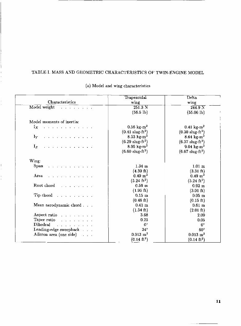
TABLE I. MASS AND GEOMETRIC CHARACTERISTICS OF TWIN-ENGINE MODEL
Trapezoidal
Model weight . . . . . . . . 251.3 N Characteristics wing
(56.5 lb)
(a) Model and wing characteristics
Delta wing
244.9 N (55.06 lb)
Model moments of inertia: Ix . . . . . . . . . . . .
Iy . . . . . . . . . . . .
lz . . . . . . . . . . . .
Wing: Span . . . . . . . . . . .
Area . . . . . . . . . . .
Root chord . . . . . . . .
Tip chord . . . . . . . . .
Mean aerodynamic chord . .
Aspect ratio . . . . . . . . Taper ratio . . . . . . . . Dihedral . . . . . . . . . Leading-edge sweepback . . . Aileron area (one side) . . .
0.56 kg-m2 (0.41 slug-ft2)
8.53 kg-m2 (6.29 slug-ft2)
8.95 kg-m2 (6.60 slug-ft2)
1.34 m
0.49 m2 (5.24 ft2)
0.59 m (1.95 ft)
0.15 m
0.41 m (1.34 ft)
3.68 0.25
0" 34"
0.013 m2 (0.14 ft2)
(4.39 ft)
(0.48 ft)
0.41 kg-m2 (0.30 slug-ft2)
8.64 kg-m2 (6.37 slug-ft2)
9.04 kg-m2 (6.67 slug-ft2)
1.01 m (3.31 ft) 0.49 m2
(5.24 ft2) 0.92 m
(3.01 ft) 0.05 m
0.61 m
2.09 0.05
0" 60"
0.013 m2 (0.14 ft2)
(0.15 f t j
(2.01 ft)
11

TABLE I. Concluded
(b) Tail characteristics
Horizontal tail: Area . . . . . . . . . . . . . . . . . . . . . . . . . . 0.165m2
(1.78 ft') Span . . . . . . . . . . . . . . . . . . . . . . . . . . . 0.75m
(2.46 ft) Aspect ratio . . . . . . . . . . . . . . . . . . . . . . . . 3.40 Taper ratio . . . . . . . . . . . . . . . . . . . . . . . . 0.33 Dihedral . . . . . . . . . . . . . . . . . . . . . . . . . -4.0"
Area (exposed) . . . . . . . . . . . . . . . . . . . . . . . 0.12 m2 (1.25 ft2)
Aspect ratio (exposed) . . . . . . . . . . . . . . - . . . . 1.22 Taper ratio (exposed) . . . . . . . . . . . . . . . . . . . . 0.25 Rudder area (aft of hinge) . . . . . . . . . . . . . . . . . 0.017 m2
(0.18 ft2) Overall fuselage length . . . . . . . . . . . . . . . . . . . 2.38 m
(7.81 f t )
Vertical tail:
12
x
13

14

Delta wing
Trapezoidal wing
(b) Sketch of two wing planforms.
Figure 2. Concluded.
15
16
a
/f
17
18
19

m L 0 c, CU 3 u CU c,
.. v) L
z c Q) m m m U c,
-E m 0 P c 0
0 0
m c 0 .- c,
3!
o
U c m c
ET c L 0 c,
c 0
.-
.- E Q) L 3
m L
- .- 0
1 0 0 0
20

A a k 0 0 A a od
Y
W
M b4
2 .e
21

22

.o
-.2
- .4
-.6
- .8
2 .4
2 .0
1.6
1.2
cL
.8
.4
0
- .4 -
2 . 4
2 .0
1.6
1.2
cD
.8
.4
0
- . 4 10 0 10 20 30 40 50 60
a, deg
Figure 9. Effects of spanwise blowing on static longitudinal characteristics for trapezoidal wing. 6 f , ~ , ~ = 0"; z/C = 0.4.
23
24
c 0
N CJ H 4 4 U
0 0
o o o a 0 \D
0 m
0 e
0 * M
a, a 8 n
0 hl
2
0
2 CJ N
I 0 6 a C O I
I I I
fi U
26

5 - 2
'4.8
Lf .O
3.6
3 a 2
2 - 8 ACL/CT
2 a ' 4
2 -0
1 *6
1.2
*8
0 5 10 15 20 25 30 35 YO Y5 50 55 a, deg
Figure 12. Effects of spanwise blowing on lift augmentation ratio for trapezoidal wing. 6 f , ~ ~ = 0"; x /F = 0.4.
26

0
-.2
-.4
- .6
-. 8
2.4
2.0
1.6
cL
1.2
.8
.4
0
cT % , L E ' deg
0 0 0
0 .12 0
0 0 2 4
n .12 24
2 . 4
2.0
1.6
cD
1 . 2
.8
.4
0
-10 0 10 20 30 40 50 60 a , d e g
Figure 13. Effects of leading-edge flap deflection and spanwise blowing on static longitudinal characteristics for trapezoidal wing. x /C = 0.4.
28
m C
2.0
1.6
1 . 2
.8
.4
0
cL
-
r
1
0
- .2
- .4
-.6
- .8 '
2.0
1 .6
1 .2
cD
.8
.4
0 -10 0 10 20 30 40 50 60
a , deg
Figure 15. Effects of spanwise-blowing thrust coefficient on static longitudinal characteristics for delta wing. x / C = 0.4.
29
N M 9 0 rn N a0 =tc 0
0 N N &I d + m . m
I- o
0
\ 2
Q
30
Q
P Ln
C
.1
0
- - 1
0
- .OOY
,008
Stable
I I 1 I I I I I I I I I
(a) CT = 0.04.
a Stable
Figure 17. Effects of longitudinal location of spanwise-blowing port on static lateral-directional stability for trapezoidal wing. 6f,LE = 0"; 6h = 0".
31

C yP
- 020
8016
mol2
C "P -008
0oq
0
-.ooq
0
cb -.ooLf
Stable
0
-10 0 10 20 30 LfO 50 60 a, deg
Stable
(b) CT = 0.12.
Figure 17. Concluded.
32

C yP
C "P
.1
0
-81
020
-016
-012
008
oo!!
0
0
p -.0oL4 c2
-10 0
cT
0 0
0 .04
0 .08
.12
Stable
U Stable
50 60
Figure 18. Effects of spanwise-blowing thrust coefficient on static lateral-directional characteristics for trapezoidal wing. 6 f , ~ ~ = 0"; x/C = 0.4.
33

I- O
=r cu 0 . . . 8 0 0 0 ai 4 0 .
34

- 020
-016
-012
-008
OOLl
0
- .OOY
- 008
0
- - OOY
-10 0 10 20 30 q0 50 60 a, de9
cT
0 0 0 .12
0 0 A .12
Stable
V
U Stable
V .T.
On
On
Off
Off
Figure 20. Effects of spanwise blowing on vertical-tail effectiveness for trapezoidal wing. S ~ , L E = 0"; x/C = 0.4.
35
36
cu 0
ru 0
-1
C yB 0
-.1
028
.02q
020
.016
.012 %
.ooq
0
- OOLf
0
- .ooq
- ,008
- -012 -10 0 10 20 30 YO 50 60
0, deg
Stable
0 Stable
Figure 22. Effects of longitudinal location of spanwise-blowing port on static lateral-directional characteristics for delta wing. CT = 0.08.
37

C yB
0
- moo4 Stable
- *008
- -012 -10 0 10 20 30 YO 50 60
a, deg
Figure 23. Effects of spanwise-blowing thrust coefficients on static lateral-directional characteristics wing. XI? = 0.4.
38
>
-1
0
-01
r
P bn
a 02Y
020
e 004
0
cT
0 0
0 .04
0 .08
.12
Stable
for delta

Y A c
n L l C
42
C
-.2
-08
.O6
- OLl
= 02
0
- -02
--04
- LO 0 10 20 30 LfO 50 a, deg
cT 0 0 0 .04 0 .12
Figure 24. Effects of spanwise blowing on rudder effectiveness for trapezoidal wing. 6, = -30"; 6 f , ~ ~ = 0"; z / F = 0.4.
39

.!4
.2
n c Y 0.0
- .2
- .L l
0 0 0
cT 0
.04
.12
c2
.06
* 02
0
- -02 - 10 0 10 20 30 LiO 50 60
a, deg
Figure 25. Effects of spanwise blowing on aileron effectiveness for trapezoidal wing. 6, = -30"; ~ I , L E = 0"; z/C = 0.4.

0 0 a .12
Figure 26. Effects of spanwise blowing on lateral control divergence parameter for trapezoidal wing. X / C = 0.4; c5f,LE = 0".
41

.2
0 - 0
- .2
- . L f
.02
0 n AC
- .02
- .oLf
cZ
-10 0 10 20 30 LfO 50 60 a, deg
cT b o , deg
0 0 -30
0 04L 0 0 12L 0
. indicates lef t port on l y
.06
.oLf
.02
0
- .02
Figure 27. Effects of asymmetric spanwise blowing as compared with aileron effectiveness for trapezoidal wing. h f , ~ ~ = 0"; x / C = 0.4.
42
C sin a + Y- P B
Cn + Cn. sin a P B
Cz t C sin a P zb
1
0
-1
-2
1.6
1.2
.8
.Lf
-0
- .Lf
-.8
cT
0 0
0 .08
U Adverse
U Stabilizing
-10 0 10 20 30 LfO 50 60 a, deg
Figure 28. Effects of spanwise blowing on dynamic lateral-directional stability derivatives obtained during rolling oscillation tests for trapezoidal wing. C ~ ~ , L E = 0'; z/? = 0.4; k = 0.08; amplitude, -5" to 5".
43

~ ~~~~ ~- ~~
18. Distribution Statement Unclassified-Unlimited
Ernie L. Anglin
NASA Langley Research Center Hampton, VA 23665
, Performing Organization Name and Address
~~ ~~
19. Security Claasif.(of this report) 20. Security Classif.(of this page) 21. No. of Pages 22. Price A03
- ~
44 Unclassified - ~- Unclassified
For sale by the National Technical Information Service, Springfield, Virginia 22161
2. Sponsoring Agency Name and Address
National Aeronautics and Space Administration Washington, DC 20546
, Report No. 2. Government Accession No. NASA TP-2431
, Title and Subtitle Low-Speed Stability and Control Wind-Tunnel Investigation of Effects of Spanwise Blowing on Fighter Flight Characteristics at High Angles of Attack
~
. Author(s)
Dale R. Satran, William P. Gilbert, and 1 L-15851
3. Recipient's Catalog No.
5. Report Date
May 1985 6. Performing Organization Code
505-43-13-01 8. Performing Organization Report No.
-
I
5. Supplementary Notes
10. Work Unit No.
11. Contract or Grant No.
13. Type of Report and Period Covered
Technical Paper 14. Sponsoring Agency Code
~
6. Abstract The Langley Research Center has recently conducted an investigation to determine the effects of spanwise blowing on two configurations representative of current fighter airplanes. The two configurations differed only in wing planform, with one incorporating a trapezoidal wing and the other a 60"delta wing. This research emphasized determining the lateral-directional characteristics, particularly in the stall/departure angle-of-attack range; however, the effects of spanwise blowing on the longitudinal aerodynamics were also determined. The wind-tunnel tests included measurement of static force and forced-oscillation aerodynamic data, visualization of the airflow changes created by the spanwise blowing, and free-flight model tests. The effects of blowing rate, chordwise location of the blowing ports, asymmetric blowing, and blowing on the conventional aerodynamic control characteristics were investigated. In the angle-of-attack regions in which the spanwise blowing substantially improved the wing upper-surface flow field (i.e., provided reattachment of the flow aft of the leading-edge vortex), improvements in both static and dynamic lateral-directional stability were observed. Results showed blowing effects on stability could be proverse or adverse depending on blowing rate, blowing port location, and wing planform. Free-flight model tests of the trapezoidal wing confirmed the beneficial effects of spanwise blowing measured in the static and dynamic force tests.
17. Key Words (Suggested by Authors(s)) Spanwise blowing Stall spin Dynamic stability hlaneuver aerodynamics Vortex lift
Subject Category 02
N A S A - L a n g l e y , 1986