Embed Size (px)
Citation preview

Lowering Costs of Hydrogen Pipelines through Use of Fiber Reinforced Polymers and Modern Steels George Rawls1, Joe Ronevich2, Andrew Slifka3
1. Savannah River National Laboratory 2. Sandia National Laboratory 3. National Institute of Standards and Technology
September 27, 2017
Fuel Cell Technologies Office Webinar

2 U.S. DEPARTMENT OF ENERGY OFFICE OF ENERGY EFFICIENCY & RENEWABLE ENERGY FUEL CELL TECHNOLOGIES OFFICE
Question and Answer
• Please type your questions to the chat box. Send to: (HOST)
2

Codification of Fiber Reinforced Polymer (FRP) for High-Pressure H2 Service
George Rawls1, Barton Smith2
1 Savannah River National Laboratory 2 Oak Ridge National Laboratory
This work was completed with funding from the U.S. Department of Energy’s Office of Energy Efficiency and Renewable Energy’s (EERE’s)
Fuel Cell Technologies Office (FCTO)

4 U.S. DEPARTMENT OF ENERGY OFFICE OF ENERGY EFFICIENCY & RENEWABLE ENERGY FUEL CELL TECHNOLOGIES OFFICE
Fiber Reinforced Polymer Hydrogen Pipelines
Existing Technology
• FRP is currently employed in the oil & gas industry • Spoolable commercial products up to 8” diameter and 2,500
psig rating. • Site manufactured products are available up to 12” diameter
and 1,000 psig rating.
Impact
• 0.5-mile lengths can be spooled for delivery to installation sites, reducing installation cost by up to 25%
• Can be manufactured on-site in lengths of 2-3 miles
• FRP is not susceptible to hydrogen embrittlement.
• FRP has superior chemical and corrosion resistance.
Spooled FRP Installation
Site Manufactured FRP
FRP Cross Section

5 U.S. DEPARTMENT OF ENERGY OFFICE OF ENERGY EFFICIENCY & RENEWABLE ENERGY FUEL CELL TECHNOLOGIES OFFICE
Methodology to Enable Use of FRP for H2 Service
• Approach: – Critically evaluate available FRP product standards through independent testing. – Define necessary changes to FRP product standards to meet the ASME Code requirements. – Build a body of data to support codification in the ASME B31.12 Hydrogen Piping Code.
5
Long Term Hydrostatic Pressure
Data Regression Line
Nominal Pressure Rating
95% Lower Prediction Lower Prediction Limit
Time
Service Factor
Hydrogen Service
Design Life
Maximum Service Pressure Hydrogen
10,000 Hours
Pres
sure
ASME B31.12 Code • Scope • Materials • Design • Fabrication • Examination • Testing • Inspection
ASME Methodology FRP Product Methodology
DOE R&D Program
6 U.S. DEPARTMENT OF ENERGY OFFICE OF ENERGY EFFICIENCY & RENEWABLE ENERGY FUEL CELL TECHNOLOGIES OFFICE
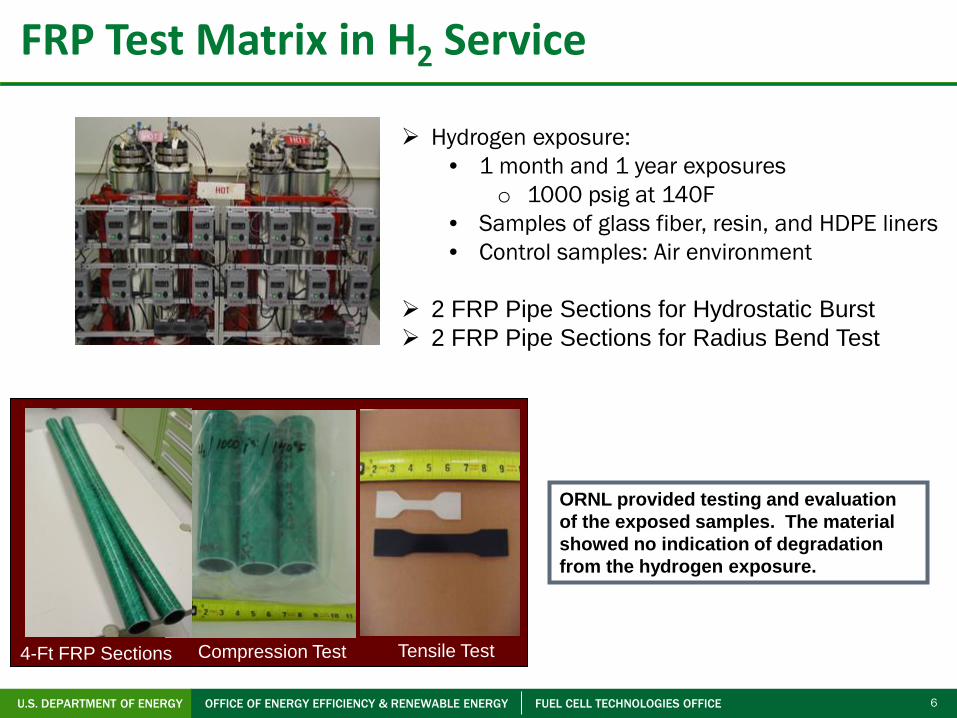
FRP Test Matrix in H2 Service
4-Ft FRP Sections Compression Test Tensile Test
ORNL provided testing and evaluation of the exposed samples. The material showed no indication of degradation from the hydrogen exposure.
Hydrogen exposure: • 1 month and 1 year exposures
o 1000 psig at 140F • Samples of glass fiber, resin, and HDPE liners • Control samples: Air environment
2 FRP Pipe Sections for Hydrostatic Burst 2 FRP Pipe Sections for Radius Bend Test

7 U.S. DEPARTMENT OF ENERGY OFFICE OF ENERGY EFFICIENCY & RENEWABLE ENERGY FUEL CELL TECHNOLOGIES OFFICE
Burst Tests of FRP in H2 Service
FRP achieves a burst pressure of > 4,000 psi (275 bar), even if flaws of detectable lengths are present.
40% Through Wall Flaws
0
1000
2000
3000
4000
5000
6000
1 2 3 4 5 6 7 8 9
Samlple
Bur
st P
ress
ure
(psi
)
Burst Testing Performed on Samples With Engineered Flaws1
Sample
1. Flaws were through 40% of pipe wall thickness

8 U.S. DEPARTMENT OF ENERGY OFFICE OF ENERGY EFFICIENCY & RENEWABLE ENERGY FUEL CELL TECHNOLOGIES OFFICE
Fatigue Testing of FRP in H2 Service
Notes: 1. Single cycle test represents burst test data 2. 750 psig fatigue test was terminated at 54,160 cycles without a structural failure 3. The fatigue tests for R = 0.3 failed at 53020 cycles. The fatigue tests for R = 0.5 failed at ≈100,000 cycles.
Primary Design Fatigue Curve
Service pressure of FRP guides fatigue life.
R = 0.1 R = 0.3 R = 0.5
Legend
100,000 10,000 1,000 100 10 1
R = 𝑃𝑃𝑃𝑃𝑃𝑃𝑃𝑃𝑃𝑃𝑃𝑃𝑃𝑃𝑃𝑃𝑚𝑚𝑚𝑚𝑚𝑚𝑃𝑃𝑃𝑃𝑃𝑃𝑃𝑃𝑃𝑃𝑃𝑃𝑃𝑃𝑃𝑃𝑚𝑚𝑚𝑚𝑚𝑚

9 U.S. DEPARTMENT OF ENERGY OFFICE OF ENERGY EFFICIENCY & RENEWABLE ENERGY FUEL CELL TECHNOLOGIES OFFICE
Design Life Assessment of FRP in H2 Service
Current data supports FRP design life of 50 years, with a 5% decrease in fiber stress and a limit on fatigue life of 28,500 cycles at an R ratio of 0.5.
Expected Cycling Due to Maintenance in Pipeline System Years of Service Fatigue Cycles1
1 12-24
20 240-480
50 600-1200
1. Assuming 1-2 cycles/month 2. Assuming 1-2 cycles/day
Expected Cycling to Supply Hydrogen Fueling Stations
Years of Service Fatigue Cycles2
1 365 - 730
20 7,300 - 14,600
50 18,250 - 36,500
Experimentation on Glass Composite Rupture Stresses

10 U.S. DEPARTMENT OF ENERGY OFFICE OF ENERGY EFFICIENCY & RENEWABLE ENERGY FUEL CELL TECHNOLOGIES OFFICE
FRP Connectors
Coupling Nut O-Ring
Seals
Compression Rings
Threaded Portion Of Coupling
• Connectors are metallic with elastomer O-ring seals: • Internal diameter of polyethylene liner is machined to a specified diameter. • Machined portion of liner is where O-rings in the metallic connector interface with
composite piping to form fluid seal. • Outer nut of the connector is tightened, mechanically compressing ferrules on the
piping, resulting in compression of the seals.
Illustration of O-Ring Extrusion Failures from Fatigue
• Extrusion failures were resolved by choosing O-rings with greater hardness level, approximately 75 durometer M.
• ASME pipeline operators expressed concern over the potential maintenance requirements of mechanical joints.

11 U.S. DEPARTMENT OF ENERGY OFFICE OF ENERGY EFFICIENCY & RENEWABLE ENERGY FUEL CELL TECHNOLOGIES OFFICE
FRP for H2 Delivery- Code Case Approval
• ASME B31.12 Codification • Approval Process
B31.12 Code Committee
B31 Standards Committee
Board on Pressure Technology
B31 Case 200 ASME B31.12 Hydrogen Piping Approval Date: October 31, 2016 Composite Piping for Hydrogen Service

12 U.S. DEPARTMENT OF ENERGY OFFICE OF ENERGY EFFICIENCY & RENEWABLE ENERGY FUEL CELL TECHNOLOGIES OFFICE
For the first time, FRP can now be used in high-pressure H2
service.
“Spoolable FRP has been established as a proven, reliable, cost effective pipeline solution in the oil and gas industry and now with the research conducted through the Hydrogen Delivery Project
and subsequent codification by ASME, the benefits of the technology can be realized for high-pressure Hydrogen applications. I'm excited to see acceptance of FRP technology expand as new
research demonstrates the capabilities of these products. FRP technology offers corrosion free alternative with improved safety and ease of installation. Under the leadership of DOE and
teamwork from project participants, I look forward to future research and the next new applications for FRP technology."
– Chris Makselon, Vice President of Sales, North America, NOV Completion & Production
Solutions

Assessment of Hydrogen Assisted Fatigue in Steel Pipelines
Joe Ronevich1, Chris San Marchi1, Brian Somerday2, Andy Slifka3, Liz Drexler3, Robert Amaro4
1 Sandia National Laboratories 2 Southwest Research Institute (Somerday formerly at SNL)
3 NIST 4 University of Alabama
This work was completed with funding from the U.S. Department of Energy’s Office of Energy Efficiency and Renewable Energy’s (EERE’s)
Fuel Cell Technologies Office (FCTO) and
the U.S. Department of Transportation

14 U.S. DEPARTMENT OF ENERGY OFFICE OF ENERGY EFFICIENCY & RENEWABLE ENERGY FUEL CELL TECHNOLOGIES OFFICE
Steel Hydrogen Pipelines
Existing Technology
• 1,600 miles of steel H2 pipeline in service today, for petrochemical industry • Pipelines are most efficient method to deliver 1,000s of kilograms of H2 long term. • H2 pipelines today are not commonly cycled in service (i.e. “fatigue”) • Pipelines are designed per ASME B31.12 Code for Hydrogen Piping and Pipelines
H2 embrittlement is seen as a risk to pipeline reliability. Pipelines are designed with thicker walls to manage this risk.
A. Elgowainy, ANL

15 U.S. DEPARTMENT OF ENERGY OFFICE OF ENERGY EFFICIENCY & RENEWABLE ENERGY FUEL CELL TECHNOLOGIES OFFICE
Impact: Use of High-Strength Steels to Lower Pipeline Costs
1. Based on 30 years of data on the costs of natural gas pipelines, excl. right-of-way.http://www.ogj.com/articles/print/volume-109/issue-1/transportation/national-lab-uses-ogj-data-to-develop-cost-equations.html
2. Fekete et al. 2015 (Int. J of Hydrogen Energy)
Using X70 (instead of X52) can result in 31% cost reduction for 24” pipe operated at 103 bar (1500 psi)2.
Cost of Steel Pipelines1
• Higher strength pipes can enable both higher pressures and lower costs • However, design codes (ASME B31.12) place penalties (increased thickness
requirements) on use of higher strength pipes in H2, restricting cost savings
https://energy.gov/sites/prod/files/2015/08/f25/fcto_myrdd_delivery.pdf

16 U.S. DEPARTMENT OF ENERGY OFFICE OF ENERGY EFFICIENCY & RENEWABLE ENERGY FUEL CELL TECHNOLOGIES OFFICE
• Fatigue: Loading of pipe caused by fluctuations in operating pressure
PH2 PH2
da/d
N (c
rack
gro
wth
rate
)
∆K (stress intensity factor range)
• Crack growth under fatigue loading can be over an order of magnitude faster in H2 Service (i.e. hydrogen assisted fatigue crack growth; HA-FCG)
HA-FCG does not preclude material from use but necessitates proper design.
Background: Hydrogen Assisted Fatigue

17 U.S. DEPARTMENT OF ENERGY OFFICE OF ENERGY EFFICIENCY & RENEWABLE ENERGY FUEL CELL TECHNOLOGIES OFFICE
P = design pressure = 3ksi (21 MPa) S = specified min yield stress t = thickness D = outside diameter = 24 in (610mm) E = longitudinal joint factor = 1 T = temp derating factor = 1
ASME B31.8 Natural Gas pipeline thickness
ASME B31.12 Hydrogen pipeline thickness Prescriptive Design Method
Current Design codes (ASME B31.12) apply thickness premiums to higher strength H2 pipelines. Research Question: Is this premium necessary?
F= design factor = 0.72 (Class 1)
F= design factor = 0.5 (Class 1) HF=Materials Performance Factor
Background: Current H2 Pipeline Design Codes

18 U.S. DEPARTMENT OF ENERGY OFFICE OF ENERGY EFFICIENCY & RENEWABLE ENERGY FUEL CELL TECHNOLOGIES OFFICE
• Instrumentation – Internal load cell in feedback loop – Crack-opening displacement
measured internally using LVDT or clip gauge
– Crack length calculated from compliance
• Mechanical loading – Triangular load-cycle waveform – Constant load amplitude
• Environment
– Supply gas: 99.9999% H2 – Pressure = 21 MPa (3 ksi) – Room temperature
H2H2
H2
H2H2H2
H2 HH
H
load
aH2
H2H2
H2H2H2
H2 HH
H
load
a
.
.
Compact Tension (C(T))
ESE(T)
Background: Measurements of Fatigue
ASTM E647
Hzfrequency 1=

19 U.S. DEPARTMENT OF ENERGY OFFICE OF ENERGY EFFICIENCY & RENEWABLE ENERGY FUEL CELL TECHNOLOGIES OFFICE
10-7
10-6
10-5
10-4
10-3
10-2
5 6 7 8 910 20 30 40 50
X100BX70AX70BX52 VintageX52 NewX80X60X65 airX65X100AB31.12
SNL data2
NIST data2
Fatigue performance does NOT appear to depend solely on strength
Results: Steels of Varying Strengths Tested in Fatigue in H2
• Good agreement between SNL and NIST data
• All pipeline fatigue data fall
within similar band • Strengths of Steels Tested:
358 to 689 MPa (SMYS1)
Fatig
ue c
rack
gro
wth
rate
(mm
/cyc
le)
∆K (MPa m1/2)
Tests at 21 MPa or 34 Mpa R = 0.5 Freq = 1 Hz
In Air @ 10 Hz
In H2 gas
1. Specified Minimum Yield Strength 2. Only represents small fraction of
pipeline data generated

20 U.S. DEPARTMENT OF ENERGY OFFICE OF ENERGY EFFICIENCY & RENEWABLE ENERGY FUEL CELL TECHNOLOGIES OFFICE
Under New Performance Based Design Method: In lieu of measuring FCGR, the following equation may be used for fatigue analysis:
Where: a1,b1… = constants
B31.12 FCGR eqn • Permits use of pipes up to SMYS of 70 ksi
(e.g. X70) with no thickness penalty • Reduces test burden • Applicable for P<3000 psi (21 MPa)
Modification enables reduction in cost of H2 steel pipe by up to 30% by reducing quantity of steel used, welding, and use of heavy machinery.
Impact: ASME B31.12 Code Modified to Permit Higher Strength Steels Without Thickness Premium
Additionally, higher strength pipes (X100) have recently demonstrated similar behavior to B31.12
FCGR curve Potential future inclusion in code.

21 U.S. DEPARTMENT OF ENERGY OFFICE OF ENERGY EFFICIENCY & RENEWABLE ENERGY FUEL CELL TECHNOLOGIES OFFICE
• By understanding relationships between microstructure and fatigue crack growth rates
Fundamental understanding of strength, residual stress, and microstructure effects on FCGR improved predictive models of steel performance
• By characterizing behavior of pipes / weld / HAZ
• By decoupling residual stress effects, particularly in welds
X100
How do we attain acceptance of novel steels?
Future Work: Greater cost savings across applications of steel in hydrogen service through fundamental R&D

Physics-based Modeling of Pipeline Steels
Joe Ronevich1, Chris San Marchi1, Brian Somerday2, Andy Slifka3, Liz Drexler3, Robert Amaro4
1 Sandia National Laboratories 2 Southwest Research Institute (Somerday formerly at SNL)
3 NIST 4 University of Alabama
This work was completed with funding from the U.S. Department of Energy’s Office of Energy Efficiency and Renewable Energy’s (EERE’s)
Fuel Cell Technologies Office (FCTO) and the U.S. Department of Transportation

23 U.S. DEPARTMENT OF ENERGY OFFICE OF ENERGY EFFICIENCY & RENEWABLE ENERGY FUEL CELL TECHNOLOGIES OFFICE
Background: H2 Embrittlement
Mechanisms: • Hydrogen induced decohesion: H2 in
lattice and at internal interfaces lowers steel cohesive strength
• Hydrogen-Enhanced Localized Plasticity
(HELP): H2 affects plastic flow
• Hydride Formation – Highly brittle hydride precipitates
results in a low energy fracture path
[1] Novak, P., et al. "A statistical, physical-based, micro-mechanical model of hydrogen-induced intergranular fracture in steel." Journal of the Mechanics and Physics of Solids 58.2 (2010): 206-226.
Brittle fracture associated with intergranular cracking [1]

24 U.S. DEPARTMENT OF ENERGY OFFICE OF ENERGY EFFICIENCY & RENEWABLE ENERGY FUEL CELL TECHNOLOGIES OFFICE
Background: HA-FCG Modeling Physics
• Hydrogen transport – Diffusion of lattice (HL) and trapped (HT)
hydrogen- Focus on HL – Microstructural constituent specific
diffusion (DF, DP) • Decohesion between grains
– Hydrogen enhanced decohesion (D) • Damage causing ductile crack growth
– fun(D, HL, HT, 𝜀𝜀𝑃𝑃𝑃𝑃) • Grain specific orientations and
constitutive models – Rotate constitutive tensor to be inline
with grain crystal structure – Elastic-plastic model for each
microstructural constituent of interest.
HL
HT
HL
HT HL
HT HL
DF DP
X52 simulation domain

25 U.S. DEPARTMENT OF ENERGY OFFICE OF ENERGY EFFICIENCY & RENEWABLE ENERGY FUEL CELL TECHNOLOGIES OFFICE
• Constitutive model – J2 Isotropic plasticity criterion used
• Hydrogen diffusion model – Implemented user defined material
(UMAT) in ABAQUS J2 plasticity Theory
Models Developed to Couple Effects of Mechanical Loading and Hydrogen
Abaqus model of H2 concentration at crack tip
0.000001
0.00001
0.0001
0.001
0.01
0.1
5 50
da/d
N (m
m/c
ycle
)
ΔK (MPa-m1/2)
6.89 MPaPrediction- 6.89 MPa
Models calibrated to X100 steel

26 U.S. DEPARTMENT OF ENERGY OFFICE OF ENERGY EFFICIENCY & RENEWABLE ENERGY FUEL CELL TECHNOLOGIES OFFICE
• Calibrated to Experimental Data from 4130 Alloy Pressure Vessels1
Model Extended to Real-World Steel Geometries
Simulation of H2 concentration around a thumbnail crack in a
pressure vessel 0
5
10
15
20
0 10000 20000 30000 40000 50000
Dept
h of
Initi
al D
efec
t (%
of w
all t
hick
ness
)
Cycles to Failure
Predicted Cycles to Failure
4130 T1 GeometryExperimental (Failed)
4130 T1 GeometryExperimental (Not Failed)
Life Prediction Bound (2X)
10,000 20,000 30,000 40,000 50,000
Cycles to Failure
Dep
th o
f Ini
tial D
efec
t (%
of w
all t
hick
ness
)
0 0 0
5
10
15
20
1. Data obtained from Sandia National Laboratories

27 U.S. DEPARTMENT OF ENERGY OFFICE OF ENERGY EFFICIENCY & RENEWABLE ENERGY FUEL CELL TECHNOLOGIES OFFICE
Finite Element Modeling of Deformation and H2 Diffusion
• Deformation and diffusion model has been implemented in ABAQUS – “Coarsely” calibrated using literature
data – Being expanded to be capable of
simulating effects of cyclic plasticity (shake-down, ratchetting, kinematic/isotropic hardening, etc.)
– Applying effective diffusivity values from literature to inform predictions
– Tessellating microstructure by use of NEPER software to simulate grains within the material
Microstructural meshing

28 U.S. DEPARTMENT OF ENERGY OFFICE OF ENERGY EFFICIENCY & RENEWABLE ENERGY FUEL CELL TECHNOLOGIES OFFICE
– Fully reversed strain-controlled tests to characterize:
• Stabilized hysteresis loop • Stabilized stress-strain response
– Strain-life characterized in air and H2
– Separated effects of elastic and plastic strains
http://wolfweb.unr.edu/homepage/yjiang/jixi_zhang.htmlby gaseous hydrogen in metals." International Journal of Fatigue 68 (2014): 56-66.
Strain-Life Model Being Developed
Creating a strain-life damage understanding in order to incorporate all sources of “damage energy,” (e.g. residual stresses, hydrogen-dislocation interactions). Focusing on X100 pipeline steel

29 U.S. DEPARTMENT OF ENERGY OFFICE OF ENERGY EFFICIENCY & RENEWABLE ENERGY FUEL CELL TECHNOLOGIES OFFICE
• Determine “Damage” laws to estimate: – Grain boundary decohesion – Lattice separation (crack growth) – Effects of hydrogen coverage
• Implement “Damage” laws in
ABAQUS through a cohesive elements and a cohesive zone law
[1] Moriconi, C., G. Hénaff, and D. Halm. "Cohesive zone modeling of fatigue crack propagation assisted by gaseous hydrogen in metals." International Journal of Fatigue 68 (2014): 56-66.
Increasing hydrogen coverage θ
Damage Laws and Hydrogen Coverage
Cohesive law dependent on the hydrogen coverage

30 U.S. DEPARTMENT OF ENERGY OFFICE OF ENERGY EFFICIENCY & RENEWABLE ENERGY FUEL CELL TECHNOLOGIES OFFICE
Conclusion
Physics-based models of hydrogen embrittlement are in early stages of development. These models will ultimately: Expedite the development of novel materials for hydrogen
service
Expand the service conditions in which existing materials can be used
Lower costs and enhance reliability of hydrogen equipment

31 U.S. DEPARTMENT OF ENERGY OFFICE OF ENERGY EFFICIENCY & RENEWABLE ENERGY FUEL CELL TECHNOLOGIES OFFICE
Materials R&D funded by the U.S. Department of Energy’s Fuel Cell Technologies Office and the U.S. Department of
Transportation has:
1. Enabled FRP to be used in high-pressure H2 service for the first time, lowering pipeline installation costs (materials and
labor) by 25%.
2. Removed thickness premiums from steels used in high-pressure H2 service, lowering steel pipeline installation costs
by up to 30%.
3. Initiated development of physics-based models of hydrogen effects in steel.

32 U.S. DEPARTMENT OF ENERGY OFFICE OF ENERGY EFFICIENCY & RENEWABLE ENERGY FUEL CELL TECHNOLOGIES OFFICE
Question and Answer
• Please type your questions to the chat box. Send to: (HOST)
32

33 U.S. DEPARTMENT OF ENERGY OFFICE OF ENERGY EFFICIENCY & RENEWABLE ENERGY FUEL CELL TECHNOLOGIES OFFICE
Thank you
hydrogenandfuelcells.energy.gov
Neha Rustagi [email protected]
Eric Parker [email protected]