Embed Size (px)
Citation preview
User Guide - English
LSI Integrated RAID SAS 3.0 Solution LSI Integrated RAID
December 2014
Copyright and Trademarks
Comments… Suggestions… Corrections…The User Documentation Department would like toknow your opinion of this manual. Your feedback helpsus optimize our documentation to suit your individual needs.
Feel free to send us your comments by e-mail to [email protected].
Certified documentation according to DIN EN ISO 9001:2008To ensure a consistently high quality standard anduser-friendliness, this documentation was created tomeet the regulations of a quality management system which complies with the requirements of the standardDIN EN ISO 9001:2008.
cognitas. Gesellschaft für Technik-Dokumentation mbHwww.cognitas.de
Copyright © 2014 Fujitsu Technology Solutions GmbH.
All rights reserved.Delivery subject to availability; right of technical modifications reserved.
All hardware and software names used are trademarks of their respective manufacturers.
TRADEMARK ACKNOWLEDGMENTLSI, the LSI logo design, and MegaRAID are trademarks or registered trademarks of LSI Corporation. MS-DOS and Windows are registered trademarks of Microsoft Corporation. Novell and Netware are registered trademarks and SUSE is a trademark of Novell, Inc. Red Hat is a registered trademark of Red Hat, Inc. Linux is a trademark of Linus Torvalds. SCO and UnixWare are registered trademarks and OpenServer is a trademark of SCO Group, Inc. FreeBSD is a registered trademark of The FreeBSD Foundation. Solaris is a trademark of Sun Microsystems, Inc. All other brand and product names may be trademarks of their respective companies.
Based on the LSI manuals:
SAS-3 Integrated RAID Solution, User Guide,November 2012, DB15-001012-00, Version 1.0
Human Interface Infrastructure Configuration Application, User Guide,September 2014, DB15-000910-03, Version 1.3
LSI Corporation- 3 -
Table of Contents
LSI Integrated RAID SAS 3.0 Solution User GuideDecember 2014
Table of Contents
Chapter 1: Introduction to the Integrated RAID Solution . . . . . . . . . . . . . . . . . . . . . . . . . . . . . . . . . . . . . . . . . . . . . . . . . . . . . . . . . . . . . . . . . . . . . . . . . . 5
1.1 Overview . . . . . . . . . . . . . . . . . . . . . . . . . . . . . . . . . . . . . . . . . . . . . . . . . . . . . . . . . . . . . . . . . . . . . . . . . . . . . . . . . . . . . . . . . . . . . . . . . . . . . . . . . . . . . . . . . . . . . . . . . . . 51.2 Benefits and Features . . . . . . . . . . . . . . . . . . . . . . . . . . . . . . . . . . . . . . . . . . . . . . . . . . . . . . . . . . . . . . . . . . . . . . . . . . . . . . . . . . . . . . . . . . . . . . . . . . . . . . . . . . . . . . . 6
1.2.1 Host Interface . . . . . . . . . . . . . . . . . . . . . . . . . . . . . . . . . . . . . . . . . . . . . . . . . . . . . . . . . . . . . . . . . . . . . . . . . . . . . . . . . . . . . . . . . . . . . . . . . . . . . . . . . . . . . . . . 61.2.2 Metadata Support . . . . . . . . . . . . . . . . . . . . . . . . . . . . . . . . . . . . . . . . . . . . . . . . . . . . . . . . . . . . . . . . . . . . . . . . . . . . . . . . . . . . . . . . . . . . . . . . . . . . . . . . . . . . 61.2.3 SMART Support . . . . . . . . . . . . . . . . . . . . . . . . . . . . . . . . . . . . . . . . . . . . . . . . . . . . . . . . . . . . . . . . . . . . . . . . . . . . . . . . . . . . . . . . . . . . . . . . . . . . . . . . . . . . . . 61.2.4 Fusion-MPT Support . . . . . . . . . . . . . . . . . . . . . . . . . . . . . . . . . . . . . . . . . . . . . . . . . . . . . . . . . . . . . . . . . . . . . . . . . . . . . . . . . . . . . . . . . . . . . . . . . . . . . . . . . 7
Chapter 2: Overview of Integrated RAID Mirrored Volumes . . . . . . . . . . . . . . . . . . . . . . . . . . . . . . . . . . . . . . . . . . . . . . . . . . . . . . . . . . . . . . . . . . . . . . . . 8
2.1 Overview . . . . . . . . . . . . . . . . . . . . . . . . . . . . . . . . . . . . . . . . . . . . . . . . . . . . . . . . . . . . . . . . . . . . . . . . . . . . . . . . . . . . . . . . . . . . . . . . . . . . . . . . . . . . . . . . . . . . . . . . . . . 82.2 Integrated Mirroring Features . . . . . . . . . . . . . . . . . . . . . . . . . . . . . . . . . . . . . . . . . . . . . . . . . . . . . . . . . . . . . . . . . . . . . . . . . . . . . . . . . . . . . . . . . . . . . . . . . . . . . . . 82.3 Operation of Mirrored Volumes . . . . . . . . . . . . . . . . . . . . . . . . . . . . . . . . . . . . . . . . . . . . . . . . . . . . . . . . . . . . . . . . . . . . . . . . . . . . . . . . . . . . . . . . . . . . . . . . . . . . . 92.4 Mirrored Volume Features . . . . . . . . . . . . . . . . . . . . . . . . . . . . . . . . . . . . . . . . . . . . . . . . . . . . . . . . . . . . . . . . . . . . . . . . . . . . . . . . . . . . . . . . . . . . . . . . . . . . . . . . 10
2.4.1 Resynchronization with Concurrent Host I/O Operation . . . . . . . . . . . . . . . . . . . . . . . . . . . . . . . . . . . . . . . . . . . . . . . . . . . . . . . . . . . . . . . . . . . . . . 102.4.2 Hot Swapping . . . . . . . . . . . . . . . . . . . . . . . . . . . . . . . . . . . . . . . . . . . . . . . . . . . . . . . . . . . . . . . . . . . . . . . . . . . . . . . . . . . . . . . . . . . . . . . . . . . . . . . . . . . . . . . 112.4.3 Hot Spare Disk . . . . . . . . . . . . . . . . . . . . . . . . . . . . . . . . . . . . . . . . . . . . . . . . . . . . . . . . . . . . . . . . . . . . . . . . . . . . . . . . . . . . . . . . . . . . . . . . . . . . . . . . . . . . . . 112.4.4 Online Capacity Expansion . . . . . . . . . . . . . . . . . . . . . . . . . . . . . . . . . . . . . . . . . . . . . . . . . . . . . . . . . . . . . . . . . . . . . . . . . . . . . . . . . . . . . . . . . . . . . . . . . . 112.4.5 Media Verification . . . . . . . . . . . . . . . . . . . . . . . . . . . . . . . . . . . . . . . . . . . . . . . . . . . . . . . . . . . . . . . . . . . . . . . . . . . . . . . . . . . . . . . . . . . . . . . . . . . . . . . . . . . 112.4.6 Disk Write Caching . . . . . . . . . . . . . . . . . . . . . . . . . . . . . . . . . . . . . . . . . . . . . . . . . . . . . . . . . . . . . . . . . . . . . . . . . . . . . . . . . . . . . . . . . . . . . . . . . . . . . . . . . . 112.4.7 NVSRAM Usage . . . . . . . . . . . . . . . . . . . . . . . . . . . . . . . . . . . . . . . . . . . . . . . . . . . . . . . . . . . . . . . . . . . . . . . . . . . . . . . . . . . . . . . . . . . . . . . . . . . . . . . . . . . . . 112.4.8 Background Initialization . . . . . . . . . . . . . . . . . . . . . . . . . . . . . . . . . . . . . . . . . . . . . . . . . . . . . . . . . . . . . . . . . . . . . . . . . . . . . . . . . . . . . . . . . . . . . . . . . . . . 122.4.9 Consistency Check . . . . . . . . . . . . . . . . . . . . . . . . . . . . . . . . . . . . . . . . . . . . . . . . . . . . . . . . . . . . . . . . . . . . . . . . . . . . . . . . . . . . . . . . . . . . . . . . . . . . . . . . . . 122.4.10 Make Data Consistent . . . . . . . . . . . . . . . . . . . . . . . . . . . . . . . . . . . . . . . . . . . . . . . . . . . . . . . . . . . . . . . . . . . . . . . . . . . . . . . . . . . . . . . . . . . . . . . . . . . . . . 12
2.5 Creating Mirrored Volumes in BIOS . . . . . . . . . . . . . . . . . . . . . . . . . . . . . . . . . . . . . . . . . . . . . . . . . . . . . . . . . . . . . . . . . . . . . . . . . . . . . . . . . . . . . . . . . . . . . . . . 122.5.1 Mirrored Volume Configuration Overview . . . . . . . . . . . . . . . . . . . . . . . . . . . . . . . . . . . . . . . . . . . . . . . . . . . . . . . . . . . . . . . . . . . . . . . . . . . . . . . . . . . . 122.5.2 Creating Mirrored Volumes . . . . . . . . . . . . . . . . . . . . . . . . . . . . . . . . . . . . . . . . . . . . . . . . . . . . . . . . . . . . . . . . . . . . . . . . . . . . . . . . . . . . . . . . . . . . . . . . . . 122.5.3 Managing Hot Spare Disks . . . . . . . . . . . . . . . . . . . . . . . . . . . . . . . . . . . . . . . . . . . . . . . . . . . . . . . . . . . . . . . . . . . . . . . . . . . . . . . . . . . . . . . . . . . . . . . . . . . 152.5.4 Other Configuration Tasks . . . . . . . . . . . . . . . . . . . . . . . . . . . . . . . . . . . . . . . . . . . . . . . . . . . . . . . . . . . . . . . . . . . . . . . . . . . . . . . . . . . . . . . . . . . . . . . . . . . 16
Chapter 3: Integrated Striping . . . . . . . . . . . . . . . . . . . . . . . . . . . . . . . . . . . . . . . . . . . . . . . . . . . . . . . . . . . . . . . . . . . . . . . . . . . . . . . . . . . . . . . . . . . . . . . . . 20
3.1 Overview of Integrated Striping . . . . . . . . . . . . . . . . . . . . . . . . . . . . . . . . . . . . . . . . . . . . . . . . . . . . . . . . . . . . . . . . . . . . . . . . . . . . . . . . . . . . . . . . . . . . . . . . . . . 203.1.1 Overview . . . . . . . . . . . . . . . . . . . . . . . . . . . . . . . . . . . . . . . . . . . . . . . . . . . . . . . . . . . . . . . . . . . . . . . . . . . . . . . . . . . . . . . . . . . . . . . . . . . . . . . . . . . . . . . . . . . 203.1.2 Integrated Striping Features . . . . . . . . . . . . . . . . . . . . . . . . . . . . . . . . . . . . . . . . . . . . . . . . . . . . . . . . . . . . . . . . . . . . . . . . . . . . . . . . . . . . . . . . . . . . . . . . . 203.1.3 Integrated Striping Description . . . . . . . . . . . . . . . . . . . . . . . . . . . . . . . . . . . . . . . . . . . . . . . . . . . . . . . . . . . . . . . . . . . . . . . . . . . . . . . . . . . . . . . . . . . . . . 20
3.2 Creating Integrated Striping Volumes in BIOS . . . . . . . . . . . . . . . . . . . . . . . . . . . . . . . . . . . . . . . . . . . . . . . . . . . . . . . . . . . . . . . . . . . . . . . . . . . . . . . . . . . . . . 223.2.1 Integrated Striping Configuration Overview . . . . . . . . . . . . . . . . . . . . . . . . . . . . . . . . . . . . . . . . . . . . . . . . . . . . . . . . . . . . . . . . . . . . . . . . . . . . . . . . . . 223.2.2 Creating Integrated Striping Volumes . . . . . . . . . . . . . . . . . . . . . . . . . . . . . . . . . . . . . . . . . . . . . . . . . . . . . . . . . . . . . . . . . . . . . . . . . . . . . . . . . . . . . . . . 223.2.3 Other Configuration Tasks . . . . . . . . . . . . . . . . . . . . . . . . . . . . . . . . . . . . . . . . . . . . . . . . . . . . . . . . . . . . . . . . . . . . . . . . . . . . . . . . . . . . . . . . . . . . . . . . . . . 24
Chapter 4: Human Interface Infrastructure Configuration Application . . . . . . . . . . . . . . . . . . . . . . . . . . . . . . . . . . . . . . . . . . . . . . . . . . . . . . . . . . . . 27
4.1 Introduction . . . . . . . . . . . . . . . . . . . . . . . . . . . . . . . . . . . . . . . . . . . . . . . . . . . . . . . . . . . . . . . . . . . . . . . . . . . . . . . . . . . . . . . . . . . . . . . . . . . . . . . . . . . . . . . . . . . . . . 274.1.1 Overview . . . . . . . . . . . . . . . . . . . . . . . . . . . . . . . . . . . . . . . . . . . . . . . . . . . . . . . . . . . . . . . . . . . . . . . . . . . . . . . . . . . . . . . . . . . . . . . . . . . . . . . . . . . . . . . . . . . 274.1.2 Controller Support . . . . . . . . . . . . . . . . . . . . . . . . . . . . . . . . . . . . . . . . . . . . . . . . . . . . . . . . . . . . . . . . . . . . . . . . . . . . . . . . . . . . . . . . . . . . . . . . . . . . . . . . . . 27
4.2 Starting the Configuration Application Interface . . . . . . . . . . . . . . . . . . . . . . . . . . . . . . . . . . . . . . . . . . . . . . . . . . . . . . . . . . . . . . . . . . . . . . . . . . . . . . . . . . . 284.3 Using the Integrated RAID Version . . . . . . . . . . . . . . . . . . . . . . . . . . . . . . . . . . . . . . . . . . . . . . . . . . . . . . . . . . . . . . . . . . . . . . . . . . . . . . . . . . . . . . . . . . . . . . . . 32
4.3.1 Managing Controllers . . . . . . . . . . . . . . . . . . . . . . . . . . . . . . . . . . . . . . . . . . . . . . . . . . . . . . . . . . . . . . . . . . . . . . . . . . . . . . . . . . . . . . . . . . . . . . . . . . . . . . . 334.3.2 Managing Virtual Disks . . . . . . . . . . . . . . . . . . . . . . . . . . . . . . . . . . . . . . . . . . . . . . . . . . . . . . . . . . . . . . . . . . . . . . . . . . . . . . . . . . . . . . . . . . . . . . . . . . . . . . 454.3.3 Managing Physical Disks . . . . . . . . . . . . . . . . . . . . . . . . . . . . . . . . . . . . . . . . . . . . . . . . . . . . . . . . . . . . . . . . . . . . . . . . . . . . . . . . . . . . . . . . . . . . . . . . . . . . 53
LSI Corporation- 4 -
LSI Integrated RAID SAS 3.0 Solution User GuideDecember 2014
Table of Contents
Appendix A: Using the SAS-3 Integrated RAID Configuration Utility . . . . . . . . . . . . . . . . . . . . . . . . . . . . . . . . . . . . . . . . . . . . . . . . . . . . . . . . . . . . . . 58A.1 Hardware and Software Requirements . . . . . . . . . . . . . . . . . . . . . . . . . . . . . . . . . . . . . . . . . . . . . . . . . . . . . . . . . . . . . . . . . . . . . . . . . . . . . . . . . . . . . . . . . . . . . 58
A.1.1 Controller Support . . . . . . . . . . . . . . . . . . . . . . . . . . . . . . . . . . . . . . . . . . . . . . . . . . . . . . . . . . . . . . . . . . . . . . . . . . . . . . . . . . . . . . . . . . . . . . . . . . . . . . . . . . 58A.1.2 Operating System and Software Support . . . . . . . . . . . . . . . . . . . . . . . . . . . . . . . . . . . . . . . . . . . . . . . . . . . . . . . . . . . . . . . . . . . . . . . . . . . . . . . . . . . . 58
A.2 Interface Description . . . . . . . . . . . . . . . . . . . . . . . . . . . . . . . . . . . . . . . . . . . . . . . . . . . . . . . . . . . . . . . . . . . . . . . . . . . . . . . . . . . . . . . . . . . . . . . . . . . . . . . . . . . . . . 59A.3 Commands . . . . . . . . . . . . . . . . . . . . . . . . . . . . . . . . . . . . . . . . . . . . . . . . . . . . . . . . . . . . . . . . . . . . . . . . . . . . . . . . . . . . . . . . . . . . . . . . . . . . . . . . . . . . . . . . . . . . . . . . 59
A.3.1 Common Command-Line Parameters . . . . . . . . . . . . . . . . . . . . . . . . . . . . . . . . . . . . . . . . . . . . . . . . . . . . . . . . . . . . . . . . . . . . . . . . . . . . . . . . . . . . . . . 60A.3.2 CREATE . . . . . . . . . . . . . . . . . . . . . . . . . . . . . . . . . . . . . . . . . . . . . . . . . . . . . . . . . . . . . . . . . . . . . . . . . . . . . . . . . . . . . . . . . . . . . . . . . . . . . . . . . . . . . . . . . . . . . 60A.3.3 DELETE . . . . . . . . . . . . . . . . . . . . . . . . . . . . . . . . . . . . . . . . . . . . . . . . . . . . . . . . . . . . . . . . . . . . . . . . . . . . . . . . . . . . . . . . . . . . . . . . . . . . . . . . . . . . . . . . . . . . . 61A.3.4 DELETEVOLUME . . . . . . . . . . . . . . . . . . . . . . . . . . . . . . . . . . . . . . . . . . . . . . . . . . . . . . . . . . . . . . . . . . . . . . . . . . . . . . . . . . . . . . . . . . . . . . . . . . . . . . . . . . . . 61A.3.5 DISPLAY . . . . . . . . . . . . . . . . . . . . . . . . . . . . . . . . . . . . . . . . . . . . . . . . . . . . . . . . . . . . . . . . . . . . . . . . . . . . . . . . . . . . . . . . . . . . . . . . . . . . . . . . . . . . . . . . . . . . 62A.3.6 HOTSPARE . . . . . . . . . . . . . . . . . . . . . . . . . . . . . . . . . . . . . . . . . . . . . . . . . . . . . . . . . . . . . . . . . . . . . . . . . . . . . . . . . . . . . . . . . . . . . . . . . . . . . . . . . . . . . . . . . . 64A.3.7 STATUS . . . . . . . . . . . . . . . . . . . . . . . . . . . . . . . . . . . . . . . . . . . . . . . . . . . . . . . . . . . . . . . . . . . . . . . . . . . . . . . . . . . . . . . . . . . . . . . . . . . . . . . . . . . . . . . . . . . . . 65A.3.8 LIST . . . . . . . . . . . . . . . . . . . . . . . . . . . . . . . . . . . . . . . . . . . . . . . . . . . . . . . . . . . . . . . . . . . . . . . . . . . . . . . . . . . . . . . . . . . . . . . . . . . . . . . . . . . . . . . . . . . . . . . . 66A.3.9 CONSTCHK . . . . . . . . . . . . . . . . . . . . . . . . . . . . . . . . . . . . . . . . . . . . . . . . . . . . . . . . . . . . . . . . . . . . . . . . . . . . . . . . . . . . . . . . . . . . . . . . . . . . . . . . . . . . . . . . . 67A.3.10 ACTIVATE . . . . . . . . . . . . . . . . . . . . . . . . . . . . . . . . . . . . . . . . . . . . . . . . . . . . . . . . . . . . . . . . . . . . . . . . . . . . . . . . . . . . . . . . . . . . . . . . . . . . . . . . . . . . . . . . . . 67A.3.11 LOCATE . . . . . . . . . . . . . . . . . . . . . . . . . . . . . . . . . . . . . . . . . . . . . . . . . . . . . . . . . . . . . . . . . . . . . . . . . . . . . . . . . . . . . . . . . . . . . . . . . . . . . . . . . . . . . . . . . . . 67A.3.12 LOGIR . . . . . . . . . . . . . . . . . . . . . . . . . . . . . . . . . . . . . . . . . . . . . . . . . . . . . . . . . . . . . . . . . . . . . . . . . . . . . . . . . . . . . . . . . . . . . . . . . . . . . . . . . . . . . . . . . . . . . 68A.3.13 BOOTIR . . . . . . . . . . . . . . . . . . . . . . . . . . . . . . . . . . . . . . . . . . . . . . . . . . . . . . . . . . . . . . . . . . . . . . . . . . . . . . . . . . . . . . . . . . . . . . . . . . . . . . . . . . . . . . . . . . . . 68A.3.14 BOOTENCL . . . . . . . . . . . . . . . . . . . . . . . . . . . . . . . . . . . . . . . . . . . . . . . . . . . . . . . . . . . . . . . . . . . . . . . . . . . . . . . . . . . . . . . . . . . . . . . . . . . . . . . . . . . . . . . . 69A.3.15 HELP . . . . . . . . . . . . . . . . . . . . . . . . . . . . . . . . . . . . . . . . . . . . . . . . . . . . . . . . . . . . . . . . . . . . . . . . . . . . . . . . . . . . . . . . . . . . . . . . . . . . . . . . . . . . . . . . . . . . . . 70
LSI Corporation- 5 -
LSI Integrated RAID SAS 3.0 Solution User GuideDecember 2014
Chapter 1: Introduction to the Integrated RAID SolutionOverview
Chapter 1: Introduction to the Integrated RAID Solution
1.1 Overview
The LSI® Integrated RAID solution provides cost benefits for the server or workstation market that requires the extra performance, storage capacity, and redundancy of a RAID configuration. The LSI Integrated RAID solution includes the following RAID features:
The Integrated Mirroring solution, which provides features of RAID 1 The Integrated Striping solution, which provides features of RAID 0
By simplifying the configuration options and by providing firmware support in its SAS-3 host adapters, LSI can offer the Integrated RAID solution at a lower cost than a hardware RAID implementation.
LSI Fusion-MPT™ firmware supports Integrated Mirroring volumes, Integrated Mirroring + Striping volumes, Integrated Mirroring Enhanced volumes, and Integrated Striping volumes. You can create up to two Integrated RAID volumes on each LSI SAS-3 controller.
The LSI Integrated RAID solution supports the following LSI SAS-3 controllers and the host bus adapters based on these controllers:
LSISAS3008 LSISAS3004
LSI Integrated RAID firmware uses the same device drivers as the standard LSI Fusion-MPT-based controllers, thereby eliminating the need for complex backup software or expensive RAID hardware. To conserve system resources, the Integrated RAID firmware operates independently from the operating system. The BIOS-based configuration utility, documented in Chapter 3, makes it easy to configure mirrored and striped volumes. The Integrated RAID solution is currently available as an optional component of the Fusion-MPT architecture on LSI SAS-3 controllers.
NOTE In this document, the terms volume, RAID volume, array, and RAID array are used interchangeably. Volume and array both appear on the screens of the BIOS-based configuration utility. The term disk means both hard disk drive (HDD) and solid state drive (SSD), and the HDDs or SSDs can support either SAS or SATA protocol.
LSI Corporation- 6 -
LSI Integrated RAID SAS 3.0 Solution User GuideDecember 2014
Chapter 1: Introduction to the Integrated RAID SolutionBenefits and Features
1.2 Benefits and Features
The LSI Integrated RAID solution has the following benefits and features:
Support for up to 10 disks per Integrated RAID volume, with one or two volumes on each SAS-3 controller. Each controller can support 14 volume drives, including one or two hot spare disks.
Support for two-disk Integrated Mirroring volumes (RAID 1). Support for disk drives with 512-byte sectors and disk drives with 4-KB sectors.
Support for online capacity expansion (OCE) for RAID 1 volumes. OCE permits you to increase the size of a RAID 1 volume by replacing the disk drives with higher-capacity drives.
Support for RAID volumes, and physical disks within a RAID volume, where the volume or disk exceeds 241 bytes (2.199 TB or 2 TiB).
Low-cost RAID volume creation, which meets the needs of most internal RAID installations. Easy installation and configuration. Support for booting from any kind of Integrated RAID volume. Ability to operate without special operating system-specific software. High reliability and data integrity.
— Nonvolatile write journaling.— Physical disks in a volume are not visible to the operating system (OS) or to application software.
Low host CPU utilization and PCI® bus utilization. Processing power provided by Fusion-MPT architecture. Shared-memory architecture minimizes external
memory requests.
1.2.1 Host Interface
The Integrated RAID host interface uses the message-passing interface. The Fusion-MPT interface gives the host OS access to the RAID volumes as well as to additional non-RAID physical disks.
1.2.2 Metadata Support
The Integrated RAID firmware supports metadata, which describes the RAID volume configuration stored on each member disk of a volume. After initialization, the firmware reads the metadata on each member disk and verifies the configuration. The firmware reduces the usable disk space for each member disk when it creates the volume to make room for the metadata.
1.2.3 SMART Support
The Self-Monitoring Analysis and Reporting Technology (SMART) monitors disk drives for signs of possible future disk failure and generates an alert if it detects such signs. The Integrated RAID firmware polls each physical disk in the volume at regular intervals. If the firmware detects a SMART ASC/ASCQ code on a physical disk in the volume, it stores the SMART data in a log.
NOTE An Integrated RAID volume must use all 512-byte-sector drives or all 4-KB-sector drives. You cannot combine the two types of drives in a single volume. Also, some operating systems do not fully support 4-KB-sector drives. Refer to the documentation for the operating system you are using.
LSI Corporation- 7 -
LSI Integrated RAID SAS 3.0 Solution User GuideDecember 2014
Chapter 1: Introduction to the Integrated RAID SolutionBenefits and Features
1.2.4 Fusion-MPT Support
The Integrated RAID BIOS uses the LSI Fusion-MPT interface to communicate to the SAS-3 controller and firmware. This process includes reading the Fusion-MPT configuration to access the parameters that define behavior between the SAS-3 controller and the devices that connect to it. The Fusion-MPT drivers for all supported operating systems implement the Fusion-MPT interface to communicate with the controller and firmware.
LSI Corporation- 8 -
LSI Integrated RAID SAS 3.0 Solution User GuideDecember 2014
Chapter 2: Overview of Integrated RAID Mirrored VolumesOverview
Chapter 2: Overview of Integrated RAID Mirrored Volumes
This chapter provides an overview of the LSI Integrated RAID features that support the creation of mirrored volumes.
2.1 Overview
As a result of the shift towards network-attached storage (NAS), Internet service providers need a cost-effective, fault-tolerant solution to protect the operating systems on small form-factor, high-density, rack-mountable servers. The mirroring features of the LSI Integrated RAID solution provide such protection for the system boot volume, which safeguards the operating system and other critical information on servers and high-performance workstations. The Integrated RAID solution supports the following types of mirrored volumes:
The Integrated Mirroring solution, which provides features of RAID 1
These three mirroring solutions provide a robust, high-performance, fault-tolerant solution to data storage needs at a lower cost than a dedicated RAID controller.
Mirrored volumes contain two disks to ten disks to provide fault-tolerant protection for critical data. Mirrored volumes also support one or two global hot spare drives, with a maximum of 14 drives on each LSI SAS-3 controller.
Each SAS-3 controller can have two global hot spare disks available to automatically replace a failed disk in the one or two mirrored volumes configured on the controller. The hot spares make the mirrored volumes even more fault tolerant.
2.2 Integrated Mirroring Features
Integrated Mirroring support the following features:
Configurations of one or two mirrored volumes on each LSI SAS-3 controller. Each volume can consist of two mirrored disks for an Integrated Mirroring volume; three to ten mirrored disks for an Integrated Mirroring Enhanced volume; or four, six, eight, or ten mirrored disks for an Integrated Mirroring + Striping volume.
(Optional) Two global hot spare disks per LSI SAS-3 controller to automatically replace failed disks in mirrored volumes.
Ability of mirrored volumes to run in optimal mode or in degraded mode if one mirrored disk in an Integrated Mirroring volume fails or if one or more mirrored disks fail in an Integrated Mirroring + Striping volume or Integrated Mirroring Enhanced volume.
Support for hot swapping. Support for OCE for RAID 1 volumes. OCE permits you to increase the size of a RAID 1 volume by replacing the
existing disk drives with higher-capacity disk drives. Data is protected during the expansion process, and the RAID 1 volume remains online.
Presentation of a single virtual drive to the operating system for each mirrored volume. Support for both SAS disks and SATA disks, although you cannot combine the two types of disks in the same
volume. However, an LSI SAS-3 controller can support one volume with SATA disks and a second volume with SAS disks.
Automatic background initialization after a volume is created.
NOTE Fourteen drives is the theoretical upper limit for a single LSI SAS-3 controller, although the controller itself might support fewer than 14 drives. You can also configure one mirrored volume and one Integrated Striping volume on the same LSI SAS controller.
LSI Corporation- 9 -
LSI Integrated RAID SAS 3.0 Solution User GuideDecember 2014
Chapter 2: Overview of Integrated RAID Mirrored VolumesOperation of Mirrored Volumes
Consistency checking. Fusion-MPT architecture. Menu-driven, BIOS-based configuration utility. Error notification, in which the drivers update an OS-specific event log. Support for SCSI Enclosure Services (SES) status LED. Write journaling, which permits automatic synchronization of potentially inconsistent data after unexpected
powerdown situations. Use of metadata to store volume configuration on disks in a mirrored volume. Automatic background resynchronization while host I/O transactions continue. Background media verification, which makes sure that data on mirrored volumes is always accessible.
2.3 Operation of Mirrored Volumes
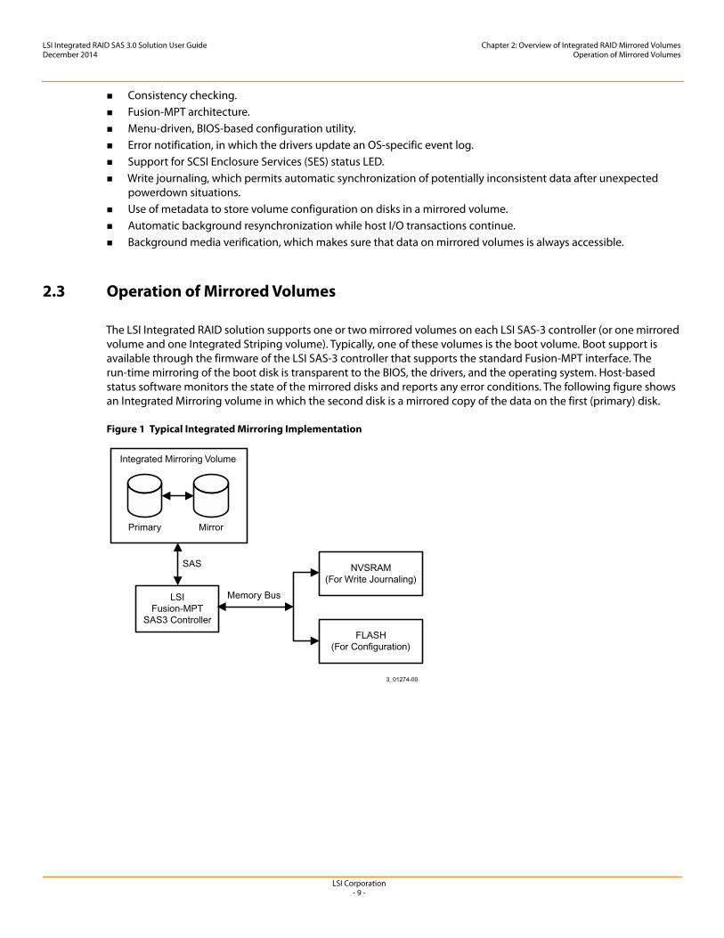
The LSI Integrated RAID solution supports one or two mirrored volumes on each LSI SAS-3 controller (or one mirrored volume and one Integrated Striping volume). Typically, one of these volumes is the boot volume. Boot support is available through the firmware of the LSI SAS-3 controller that supports the standard Fusion-MPT interface. The run-time mirroring of the boot disk is transparent to the BIOS, the drivers, and the operating system. Host-based status software monitors the state of the mirrored disks and reports any error conditions. The following figure shows an Integrated Mirroring volume in which the second disk is a mirrored copy of the data on the first (primary) disk.
Figure 1 Typical Integrated Mirroring Implementation
LSI Corporation- 10 -
LSI Integrated RAID SAS 3.0 Solution User GuideDecember 2014
Chapter 2: Overview of Integrated RAID Mirrored VolumesMirrored Volume Features
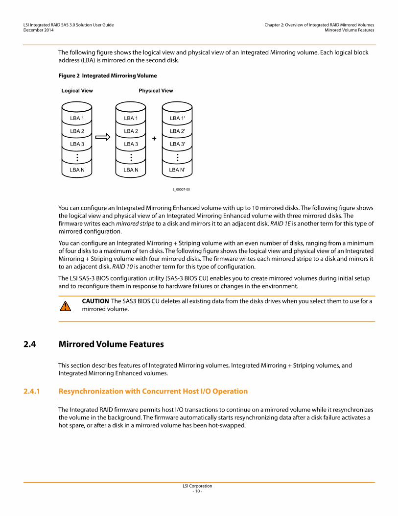
The following figure shows the logical view and physical view of an Integrated Mirroring volume. Each logical block address (LBA) is mirrored on the second disk.
Figure 2 Integrated Mirroring Volume
You can configure an Integrated Mirroring Enhanced volume with up to 10 mirrored disks. The following figure shows the logical view and physical view of an Integrated Mirroring Enhanced volume with three mirrored disks. The firmware writes each mirrored stripe to a disk and mirrors it to an adjacent disk. RAID 1E is another term for this type of mirrored configuration.
You can configure an Integrated Mirroring + Striping volume with an even number of disks, ranging from a minimum of four disks to a maximum of ten disks. The following figure shows the logical view and physical view of an Integrated Mirroring + Striping volume with four mirrored disks. The firmware writes each mirrored stripe to a disk and mirrors it to an adjacent disk. RAID 10 is another term for this type of configuration.
The LSI SAS-3 BIOS configuration utility (SAS-3 BIOS CU) enables you to create mirrored volumes during initial setup and to reconfigure them in response to hardware failures or changes in the environment.
2.4 Mirrored Volume Features
This section describes features of Integrated Mirroring volumes, Integrated Mirroring + Striping volumes, and Integrated Mirroring Enhanced volumes.
2.4.1 Resynchronization with Concurrent Host I/O Operation
The Integrated RAID firmware permits host I/O transactions to continue on a mirrored volume while it resynchronizes the volume in the background. The firmware automatically starts resynchronizing data after a disk failure activates a hot spare, or after a disk in a mirrored volume has been hot-swapped.
CAUTION The SAS3 BIOS CU deletes all existing data from the disks drives when you select them to use for a mirrored volume.
3_00007-00
LBA 1
LBA 2
LBA 3
LBA N
LBA 1
LBA 2
LBA 3
LBA N
LBA 1'
LBA 2'
LBA 3'
LBA N’
+
Physical ViewLogical View
LSI Corporation- 11 -
LSI Integrated RAID SAS 3.0 Solution User GuideDecember 2014
Chapter 2: Overview of Integrated RAID Mirrored VolumesMirrored Volume Features
2.4.2 Hot Swapping
The Integrated RAID firmware supports hot swapping, and it automatically resynchronizes the hot-swapped disk in the background without any host or user intervention. The firmware detects hot-swap removal and disk insertion.
Following a hot-swap event, the firmware verifies that the new physical disk has enough capacity for the mirrored volume. The firmware resynchronizes all replaced hot-swapped disks, even if the same disk is removed and then re-inserted. In a mirrored volume with an even number of disks, the firmware marks the hot-swapped disk as a secondary disk and the other disk with data as the primary disk. The firmware resynchronizes all data from the primary disk onto the new secondary disk. In a mirrored volume with an odd number of disks, primary and secondary sets include three disks instead of two disks.
2.4.3 Hot Spare Disk
You can configure two disks as global hot spare disks to protect data on the mirrored volumes configured on the SAS-3 controller. If the Integrated RAID firmware fails one of the mirrored disks, it automatically replaces the failed disk with a hot spare disk and then resynchronizes the mirrored data. The firmware automatically receives a notification when a hot spare replaces the failed disk, and it then designates that disk as the new hot spare.
2.4.4 Online Capacity Expansion
The OCE feature enables you to expand the capacity of an existing two-disk Integrated Mirroring (RAID 1) volume by replacing the original disk drives with higher-capacity drives that have the same protocol (SAS or SATA).
After you replace the disk drives and run the OCE command, you must use a commercial tool specific to the operating system to move, or increase the size of, the partition on the volume.
2.4.5 Media Verification
The Integrated RAID firmware supports a background media verification feature that runs at regular intervals when the mirrored volume is in the Optimal state. If the verification command fails for any reason, the firmware reads the other disk’s data for this segment and writes it to the failing disk in an attempt to refresh the data. The firmware periodically writes the current media verification logical block address to nonvolatile memory so the media verification can continue from where it stopped prior to a power cycle.
2.4.6 Disk Write Caching
By default, the Integrated RAID firmware disables disk write caching for mirrored volumes to make sure that the write journal entry stored in nonvolatile static RAM (NVSRAM) is always valid. If you enable disk write caching (not recommended), you might cause the disk write log to be invalid.
2.4.7 NVSRAM Usage
The Integrated RAID firmware requires at least a 32-KB NVSRAM to perform write journaling for mirrored volumes on LSI SAS-3 controllers. The NVSRAM also preserves configuration information across reboots. The firmware uses write journaling to verify that the disks in the mirrored volume are synchronized with each other.
NOTE The replacement drives must have at least 50 GB more capacity than the original drives of the volume.
LSI Corporation- 12 -
LSI Integrated RAID SAS 3.0 Solution User GuideDecember 2014
Chapter 2: Overview of Integrated RAID Mirrored VolumesCreating Mirrored Volumes in BIOS
2.4.8 Background Initialization
Background initialization (BGI) is the process of copying data from primary to secondary disks in a mirrored volume. The Integrated RAID firmware starts BGI automatically as a background task when it creates a volume. The volume remains in the Optimal state while BGI is in progress.
2.4.9 Consistency Check
A consistency check is a background process that reads data from primary and secondary disks in a mirrored volume and compares it to make sure the data is identical on both disks. Use the LSI SAS-3 BIOS Configuration Utility to run a consistency check on a mirrored volume.
2.4.10 Make Data Consistent
If it is enabled in the Integrated RAID firmware, the make data consistent (MDC) process starts automatically and runs in the background when you move a redundant volume from one LSI SAS-3 controller to another LSI SAS-3 controller. MDC compares the data on the primary and secondary disks. If MDC finds inconsistencies, it copies data from the primary disk to the secondary disk.
2.5 Creating Mirrored Volumes in BIOS
This chapter explains how to create Integrated Mirroring volumes with the LSI SAS-3 BIOS Configuration Utility (SAS3 BIOS CU).
2.5.1 Mirrored Volume Configuration Overview
The LSI SAS3 BIOS CU is a menu-driven utility program that enables you to easily configure and manage Integrated RAID volumes. You can use the SAS3 BIOS CU to create one or two mirrored volumes on each LSI SAS-3 controller, with up to two optional global hot spare disks. You must connect all disks in a mirrored volume to the same LSI SAS-3 controller.
Although you can use disks of different sizes in mirrored volumes, the smallest disk in the volume determines the logical size of all disks in the volume. In other words, the volume does not use the excess space of the higher-capacity member disks. For example, if you create an Integrated Mirroring Enhanced volume with two 100-GB disks and two 120-GB disks, the volume uses only 100 GB on each of the 120-GB disks.
See Chapter 2 for more information about the features of Integrated Mirroring, Integrated Mirroring + Striping, and Integrated Mirroring Enhanced volumes.
2.5.2 Creating Mirrored Volumes
The SAS3 BIOS CU is part of the Fusion-MPT BIOS. When the BIOS loads during the startup sequence and you see the message about the LSI Configuration Utility, press Ctrl-C to start the SAS3 BIOS CU. When you start the SAS3 BIOS CU, the message changes to the following:
Please wait, invoking SAS Configuration Utility...
After a brief pause, the main menu (Adapter List window) of the SAS3 BIOS CU appears. On some systems, however, the following message appears next:
LSI Corp Configuration Utility will load following initialization!
LSI Corporation- 13 -
LSI Integrated RAID SAS 3.0 Solution User GuideDecember 2014
Chapter 2: Overview of Integrated RAID Mirrored VolumesCreating Mirrored Volumes in BIOS
In this case, the SAS3 BIOS CU loads after the system completes its power-on self-test.
You can configure one or two Integrated Mirroring, Integrated Mirroring + Striping, and Integrated Mirroring Enhanced volumes on each LSI SAS-3 controller. Alternatively, you can configure one mirrored volume and one Integrated Striping volume on the same controller, up to a maximum of 14 disk drives for the two volumes. (The maximum number includes one or two optional hot spare disks for the mirrored volume or volumes.) Additional information about configuring a RAID volume follows:
All physical disks in a volume must be either SATA (with extended command set support) or SAS (with SMART support). You cannot combine SAS and SATA disks in the same volume. However, you can create one volume with SAS disks and a second volume with SATA disks on the same controller.
Disks in the volume must have 512-byte blocks and must not have removable media. Integrated Mirroring volumes must have two disks, Integrated Mirroring Enhanced volumes contain three disks to
ten disks, and Integrated Mirroring + Striping volumes can have four, six, eight, or ten disks.
2.5.2.1 Creating an Integrated Mirroring Volume
Follow these steps to create a two-disk Integrated Mirroring (RAID 1) volume with the SAS3 BIOS CU. The steps begin with the Adapter List window that appears when the SAS3 BIOS CU starts.
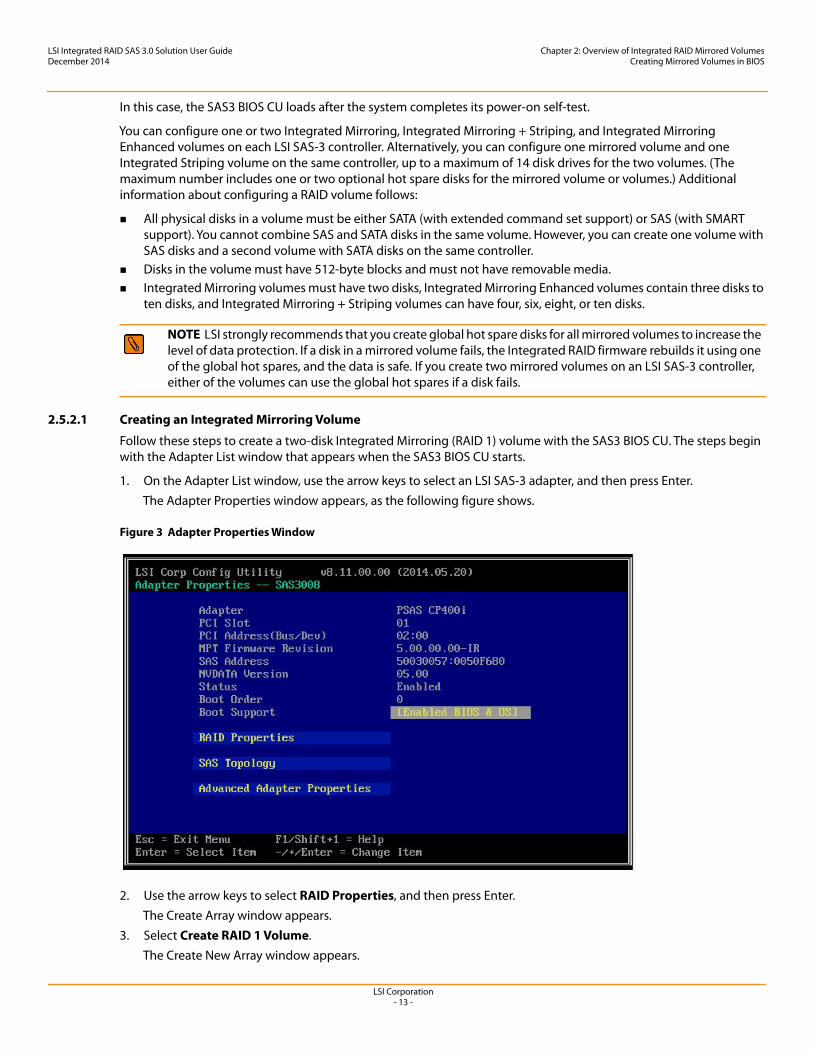
1. On the Adapter List window, use the arrow keys to select an LSI SAS-3 adapter, and then press Enter.The Adapter Properties window appears, as the following figure shows.
Figure 3 Adapter Properties Window
2. Use the arrow keys to select RAID Properties, and then press Enter.The Create Array window appears.
3. Select Create RAID 1 Volume.The Create New Array window appears.
NOTE LSI strongly recommends that you create global hot spare disks for all mirrored volumes to increase the level of data protection. If a disk in a mirrored volume fails, the Integrated RAID firmware rebuilds it using one of the global hot spares, and the data is safe. If you create two mirrored volumes on an LSI SAS-3 controller, either of the volumes can use the global hot spares if a disk fails.
LSI Corporation- 14 -
LSI Integrated RAID SAS 3.0 Solution User GuideDecember 2014
Chapter 2: Overview of Integrated RAID Mirrored VolumesCreating Mirrored Volumes in BIOS
4. Move the cursor to the RAID Disk column and select a line that has a No entry in this column, indicating that the disk is not already part of the volume you are creating. To add the disk to the new array, change the No to Yes by pressing the space bar.This disk is the Primary disk in the array.
5. Move the cursor to another line and press the space bar to add the second disk to the array.This disk is the Secondary disk in the array.
6. Press C to create the array.A menu window appears.
7. From the menu options, select Save changes then exit this menu. A message appears briefly, and then the SAS3 BIOS CU returns to the Adapter Properties window. Initialization of the new array continues in the background.
2.5.2.2 Expanding an Integrated Mirroring Volume with OCE
Use the OCE feature to expand the capacity of a two-disk Integrated Mirroring (RAID 1) volume by replacing the original disks with two higher-capacity disk drives while the volume remains online. This process maintains data integrity at all times, even if one of the disks fails during the replacement process. The new disks must have at least 50 GB more capacity than the disks they are replacing, and they must use the same protocol (SAS or SATA) as the disks they are replacing.
Follow these steps to expand an existing RAID 1 volume with OCE.
1. Physically replace one of the two volume disk drives with a drive that has at least 50 GB more capacity.If necessary, you can identify the disks in the volume by following the instructions in Section 2.5.4.5, Locating Disk Drives in a Volume.
2. Wait until synchronization completes on the new disk and the volume returns to the Optimal state, as indicated in the Adapter Properties window of the SAS3 BIOS CU.
3. Physically replace the other volume disk drive with a drive that has at least 50 GB more capacity.4. Again, wait until synchronization completes on the new disk and the volume returns to the Optimal state.5. In the Adapter List window of the SAS3 BIOS CU, use the arrow keys to select the LSI SAS adapter with the RAID 1
volume, and then press Enter.The Adapter Properties window appears.
6. Use the arrow keys to select RAID Properties, and then press Enter.The Select New Array Type window appears.
7. Select View Existing Array. The View Array window appears. If necessary, press Alt + N to switch to the RAID 1 volume with the new, higher-capacity disk drives.
CAUTION The SAS3 BIOS CU deletes all existing data from the disks drives when you select them to use in a mirrored volume.
NOTE To create a second Integrated Mirroring volume, repeat these instructions starting with step 2. Alternatively, follow the instructions in the following section to create an Integrated Mirroring Enhanced or Integrated Mirroring + Striping volume.
NOTE See the instructions in Section 2.5.3, Managing Hot Spare Disks, if you want to create one or two global hot spares.
LSI Corporation- 15 -
LSI Integrated RAID SAS 3.0 Solution User GuideDecember 2014
Chapter 2: Overview of Integrated RAID Mirrored VolumesCreating Mirrored Volumes in BIOS
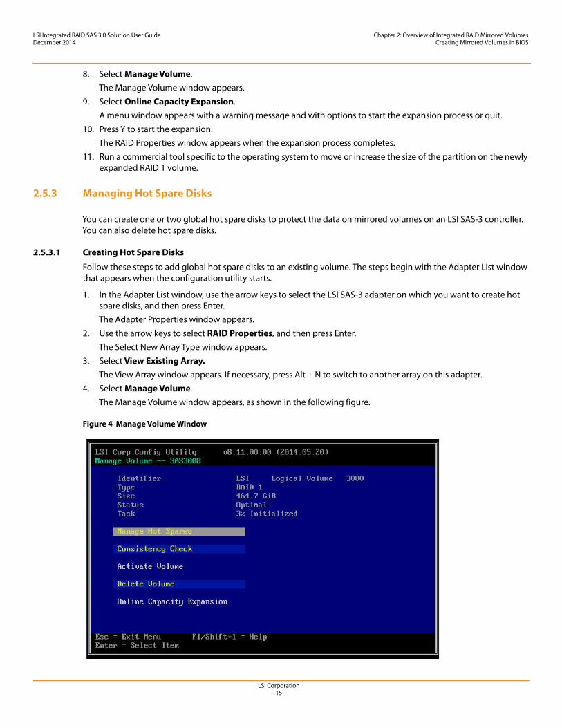
8. Select Manage Volume.The Manage Volume window appears.
9. Select Online Capacity Expansion.A menu window appears with a warning message and with options to start the expansion process or quit.
10. Press Y to start the expansion.The RAID Properties window appears when the expansion process completes.
11. Run a commercial tool specific to the operating system to move or increase the size of the partition on the newly expanded RAID 1 volume.
2.5.3 Managing Hot Spare Disks
You can create one or two global hot spare disks to protect the data on mirrored volumes on an LSI SAS-3 controller. You can also delete hot spare disks.
2.5.3.1 Creating Hot Spare Disks
Follow these steps to add global hot spare disks to an existing volume. The steps begin with the Adapter List window that appears when the configuration utility starts.
1. In the Adapter List window, use the arrow keys to select the LSI SAS-3 adapter on which you want to create hot spare disks, and then press Enter.The Adapter Properties window appears.
2. Use the arrow keys to select RAID Properties, and then press Enter.The Select New Array Type window appears.
3. Select View Existing Array. The View Array window appears. If necessary, press Alt + N to switch to another array on this adapter.
4. Select Manage Volume.The Manage Volume window appears, as shown in the following figure.
Figure 4 Manage Volume Window
LSI Corporation- 16 -
LSI Integrated RAID SAS 3.0 Solution User GuideDecember 2014
Chapter 2: Overview of Integrated RAID Mirrored VolumesCreating Mirrored Volumes in BIOS
5. Select Manage Hot Spares.The Manage Hot Spares window appears.
6. Identify a disk that is not part of a RAID array (that is, the value in the Drive Status column is not RAID) and that is not already identified as a hot spare disk.A global hot spare disk must have 512-byte blocks and nonremovable media. The disk type must be either SATA with extended command set support or SAS with SMART support.
7. Select the Hot Spr (Hot Spare) field for this disk, and press the space bar. The Hot Spare status changes to Yes.
8. (Optional) Repeat the preceding step to select a second global hot spare disk.9. Press C to create the hot spare disk.
A menu window appears. An error message appears if the selected disk is not at least as large as the smallest disk used in the existing array or arrays. An error message also appears if you try to add a SATA disk as a hot spare for arrays that use SAS disks, or if you try to add a SAS disk as a hot spare for arrays that use SATA disks.
10. Select Save changes then exit this menu to create the hot spare disk or disks.The SAS3 BIOS CU pauses while it configures the global hot spares.
2.5.3.2 Deleting a Hot Spare Disk
Follow these steps to delete a global hot spare disk.
1. Access the Manage Hot Spares window by following the first five steps of the previous section.2. Select a hot spare disk for deletion, and press C.3. Select Save changes then exit this menu to complete the deletion of the hot spare disk.
The configuration utility pauses while it removes the global hot spare.
2.5.4 Other Configuration Tasks
This section explains how to perform other configuration and maintenance tasks for mirrored arrays.
2.5.4.1 Viewing Array Properties
Follow these steps to view the RAID properties of a mirrored array.
1. In the SAS3 BIOS CU, select an LSI SAS-3 adapter from the adapter list. The Adapter Properties window appears.
2. Select RAID Properties.The Select New Array Type window appears.
3. Select View Existing Array.The View Array window appears, showing information about the array and each disk in it. The window includes global hot spare information, if any exists.
NOTE If you create one array using SAS disks, another array using SATA disks, and one or two global hot spare disks, the hot spare disks only appear when you view the mirrored array that uses the same type of disks as the hot spare disks.
LSI Corporation- 17 -
LSI Integrated RAID SAS 3.0 Solution User GuideDecember 2014
Chapter 2: Overview of Integrated RAID Mirrored VolumesCreating Mirrored Volumes in BIOS
2.5.4.2 Running a Consistency Check
Use the Consistency Check command to verify that the data is synchronized on the mirrored disks in the array.
Follow these steps to run a consistency check on a selected mirrored array:
1. In the Adapter List window, use the arrow keys to select an LSI SAS adapter.The Adapter Properties window appears.
2. Use the arrow keys to select RAID Properties, and then press Enter.The Select New Array Type window appears.
3. Select View Existing Array. The View Array window appears. If necessary, press Alt + N to switch to another array on this adapter.
4. Select Manage Volume.The Manage Volume window appears.
5. Select Consistency Check on the Manage Volume window.A menu window appears.
6. Press Y to start the consistency check.The consistency check runs in the background. If it encounters any data miscompares, it stores the information in a bad block table.
2.5.4.3 Activating an Array
An array can become inactive if, for example, you remove it from one controller or computer and install it on a different one. The Activate Array option permits you to reactivate an inactive array.
Follow these steps to activate a selected array.
1. In the Adapter List window, use the arrow keys to select an LSI SAS adapter and press Enter.The Adapter Properties window appears.
2. Select RAID Properties, and then press Enter.The Select New Array Type window appears.
3. Select View Existing Array. The View Array window appears. If necessary, press Alt + N to switch to another array on this adapter.
4. Select Manage Volume.The Manage Volume window appears.
5. Select Activate Array on the Manage Volume window.A menu window appears.
6. Press Y to activate the array.The array becomes active after a pause.
2.5.4.4 Deleting an Array
Follow these steps to delete a selected array.
1. In the Adapter List window, use the arrow keys to select an LSI SAS adapter.The Adapter Properties window appears.
2. Use the arrow keys to select RAID Properties, and then press Enter.The Select New Array Type window appears.
CAUTION Before you delete an array, be sure to back up all data on the array that you want to keep.
LSI Corporation- 18 -
LSI Integrated RAID SAS 3.0 Solution User GuideDecember 2014
Chapter 2: Overview of Integrated RAID Mirrored VolumesCreating Mirrored Volumes in BIOS
3. Select View Existing Array. The View Array window appears. If necessary, press Alt + N to switch to another array on this adapter.
4. Select Manage Volume.The Manage Volume window appears.
5. Select Delete Array.A menu window appears.
6. Either press Y to delete the array, or press N to cancel the deletion process.After a pause, the utility deletes the array. If there is another remaining array and one or two hot spare disks, the BIOS checks the hot spare disks to determine if they are compatible with the remaining array. If they are not compatible (too small or wrong disk type), the BIOS deletes them also.
2.5.4.5 Locating Disk Drives in a Volume
You can use the SAS3 BIOS CU to locate and identify a specific physical disk drive in a disk enclosure by flashing the drive’s LED. You can also flash the LEDs of all the disk drives in a RAID volume, if they are in a disk enclosure.
When you add a disk drive to a new mirrored volume, the LED on the disk drive starts flashing. The LED stops flashing when you finish creating the volume.
To locate disk drives by flashing their LEDs, follow these steps.
1. Select the desired SAS-3 controller on the Adapter List window, and press Enter.The Adapter Properties window appears.
2. Highlight SAS Topology, and press Enter.The SAS Topology window appears.
3. Select the disk in the Device Identifier column, and press Enter. The LED on the disk flashes until you press a key to stop it.
4. To identify all the disk drives in a volume, select the volume in the left column of the SAS Topology window, and press Enter. The LEDs flash on all disk drives in the volume until you press a key to stop them.
2.5.4.6 Selecting a Boot Disk
You can select a boot disk in the SAS Topology window. The next time you boot the computer, the firmware moves this disk to scan ID 0, making it the new boot disk. This feature makes it easier to set BIOS boot device options and to keep the boot device constant during device additions and removals. You can also select an alternative boot device. If the BIOS cannot find the preferred boot device when it loads, it attempts to boot from the alternative device.
Follow these steps to select a boot disk.
1. In the SAS3 BIOS CU, select an adapter from the adapter list.2. Select the SAS Topology option.
If a device is currently designated as the boot device, the Device Info column on the SAS Topology window lists the word Boot, as shown in the following figure.
NOTE The LEDs on the disk drives flash as previously described if the firmware configuration is correct and the drives are in a disk enclosure.
LSI Corporation- 19 -
LSI Integrated RAID SAS 3.0 Solution User GuideDecember 2014
Chapter 2: Overview of Integrated RAID Mirrored VolumesCreating Mirrored Volumes in BIOS
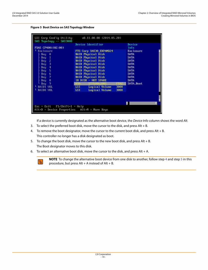
Figure 5 Boot Device on SAS Topology Window
If a device is currently designated as the alternative boot device, the Device Info column shows the word Alt.3. To select the preferred boot disk, move the cursor to the disk, and press Alt + B.4. To remove the boot designator, move the cursor to the current boot disk, and press Alt + B.
This controller no longer has a disk designated as boot.5. To change the boot disk, move the cursor to the new boot disk, and press Alt + B.
The Boot designator moves to this disk.6. To select an alternative boot disk, move the cursor to the disk, and press Alt + A.
NOTE To change the alternative boot device from one disk to another, follow step 4 and step 5 in this procedure, but press Alt + A instead of Alt + B.
LSI Corporation- 20 -
LSI Integrated RAID SAS 3.0 Solution User GuideDecember 2014
Chapter 3: Integrated StripingOverview of Integrated Striping
Chapter 3: Integrated Striping
3.1 Overview of Integrated Striping
This chapter provides an overview of the LSI Integrated RAID features that support the creation of striped volumes.
3.1.1 Overview
The LSI Integrated RAID solution enables you to create Integrated Striping volumes for applications that require the faster performance and increased storage capacity of striping. The low-cost Integrated Striping feature has many of the advantages of more expensive RAID striping solutions. An Integrated Striping volume can be the boot disk or a data disk.
The Integrated Striping solution provides better performance and more capacity than individual disks, without burdening the host CPU. The firmware distributes host I/O transactions over multiple disks and presents the disks to the OS as a single volume. In general, striping is transparent to the BIOS, the drivers, and the operating system.
Use the LSI SAS3 BIOS CU to configure Integrated Striping volumes.
3.1.2 Integrated Striping Features
Integrated Striping supports the following features:
Support for RAID volumes with two disks to ten disks Support for two Integrated Striping volumes with up to 14 drives total on a SAS-3 controller Support for combining one Integrated Striping volume and one Integrated Mirroring, Integrated Mirroring +
Striping, or Integrated Mirroring Enhanced volume on a single controller Support for both SAS and SATA drives, although you cannot combine the two types of drives in one volume Fusion-MPT architecture Easy-to-use SAS-3 BIOS configuration utility Error notification Disk write caching, which is enabled by default on all Integrated Striping volumes Use of metadata to store volume configurations on disks OS-specific event log Error display inside the Fusion-MPT BIOS SES status LED support for drives used in Integrated Striping volumes
3.1.3 Integrated Striping Description
On Integrated Striping volumes, the firmware writes data across multiple disks instead of onto one disk by partitioning each disk’s storage space into 64-KB stripes. The firmware interleaves the stripes in such a way that the combined storage space consists alternately of stripes from each disk.
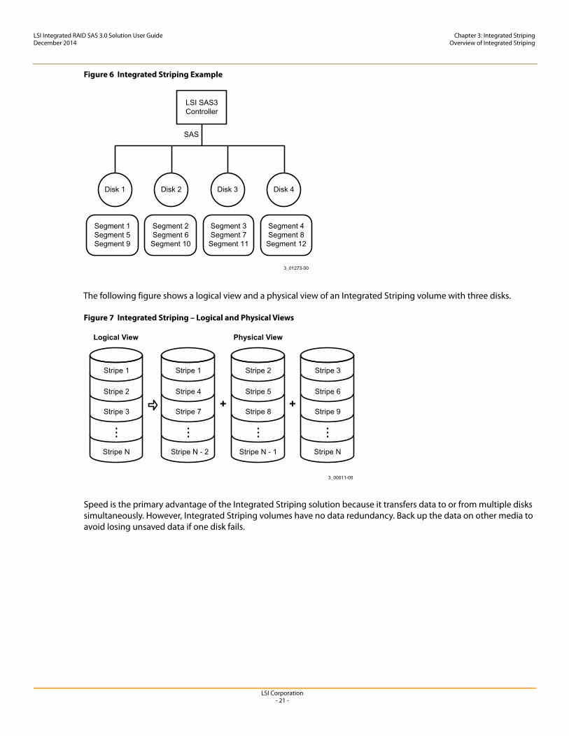
The following figure shows an example of Integrated Striping. In this example, the firmware writes segment 1 to disk 1, segment 2 to disk 2, segment 3 to disk 3, and so on. When the firmware reaches the end of the disk list, it continues writing data at the next available segment of disk 1.
LSI Corporation- 21 -
LSI Integrated RAID SAS 3.0 Solution User GuideDecember 2014
Chapter 3: Integrated StripingOverview of Integrated Striping
Figure 6 Integrated Striping Example
The following figure shows a logical view and a physical view of an Integrated Striping volume with three disks.
Figure 7 Integrated Striping – Logical and Physical Views
Speed is the primary advantage of the Integrated Striping solution because it transfers data to or from multiple disks simultaneously. However, Integrated Striping volumes have no data redundancy. Back up the data on other media to avoid losing unsaved data if one disk fails.
LSI Corporation- 22 -
LSI Integrated RAID SAS 3.0 Solution User GuideDecember 2014
Chapter 3: Integrated StripingCreating Integrated Striping Volumes in BIOS
3.2 Creating Integrated Striping Volumes in BIOS
This chapter explains how to create Integrated Striping volumes using the LSI SAS-3 BIOS Configuration Utility (SAS3 BIOS CU).
3.2.1 Integrated Striping Configuration Overview
The LSI SAS3 BIOS CU is a menu-driven utility program that enables you to easily configure and manage Integrated RAID volumes. Use the SAS3 BIOS CU to create one or two Integrated Striping volumes on each LSI SAS-3 controller. Each volume contains two drives to ten drives. All disks in an Integrated Striping volume must be connected to the same LSI SAS-3 controller.
Although you can use disks of different sizes in Integrated Striping volumes, the smallest disk in the volume determines the logical size of all disks in the volume. In other words, the firmware does not use the excess space of the higher-capacity member disks. For example, if you create an Integrated Striping volume with two 100-GB disks and two 120-GB disks, the firmware uses only 100 GB on each of the 120-GB disks for the volume. The supported stripe size is 64 KB.
See Chapter 2 for more information about Integrated Striping volumes.
3.2.2 Creating Integrated Striping Volumes
The SAS3 BIOS CU is part of the Fusion-MPT BIOS. When the BIOS loads during boot and you see the message about the LSI Configuration Utility, press Ctrl-C to start the SAS3 BIOS CU. After you start the SAS3 BIOS CU, the message changes to the following:
Please wait, invoking SAS Configuration Utility...
After a brief pause, the main menu of the SAS3 BIOS CU appears. On some systems, however, the following message appears next:
LSI Corp Configuration Utility will load following initialization!
In this case, the SAS3 BIOS CU loads after the system completes its power-on self-test.
Each LSI controller can support one or two Integrated RAID volumes. The volumes can include two Integrated Striping (RAID 0) volumes, two mirrored volumes, or one volume of each type. The two volumes can have a maximum of 14 disk drives. (This configuration includes one or two hot spare disks for mirrored volumes.)
The following guidelines apply when creating an Integrated Striping volume:
All physical disks in the volume must be either SATA (with extended command set support) or SAS (with SMART support). You cannot combine SAS and SATA disks in the same volume. However, it is possible to configure one volume with SAS disks and one volume with SATA disks on the same controller.
Disks in the volume must have 512-byte blocks and must not have removable media. Integrated Striping volumes must have at least 2 disks and no more than 10 disks. Integrated Striping volumes do
not support hot spare disks.
LSI Corporation- 23 -
LSI Integrated RAID SAS 3.0 Solution User GuideDecember 2014
Chapter 3: Integrated StripingCreating Integrated Striping Volumes in BIOS
Follow these steps to configure an Integrated Striping volume with the SAS3 BIOS CU. The steps begin with the Adapter List window that appears when the SAS3 BIOS CU starts.
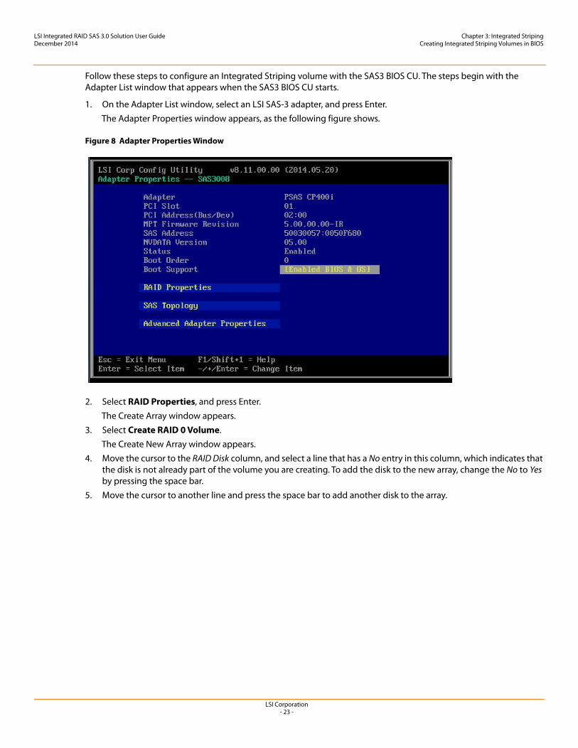
1. On the Adapter List window, select an LSI SAS-3 adapter, and press Enter.The Adapter Properties window appears, as the following figure shows.
Figure 8 Adapter Properties Window
2. Select RAID Properties, and press Enter.The Create Array window appears.
3. Select Create RAID 0 Volume.The Create New Array window appears.
4. Move the cursor to the RAID Disk column, and select a line that has a No entry in this column, which indicates that the disk is not already part of the volume you are creating. To add the disk to the new array, change the No to Yes by pressing the space bar.
5. Move the cursor to another line and press the space bar to add another disk to the array.
LSI Corporation- 24 -
LSI Integrated RAID SAS 3.0 Solution User GuideDecember 2014
Chapter 3: Integrated StripingCreating Integrated Striping Volumes in BIOS
6. Continue adding disks in this way until you reach the desired number of disks.7. Press C to create the array.
A menu appears.8. From the menu options, select Save changes then exit this menu.
A message appears briefly, and then the SAS3 BIOS CU returns to the Adapter Properties window. Initialization of the new array continues in the background.
3.2.3 Other Configuration Tasks
This section explains how to perform other configuration and maintenance tasks for Integrated Striping arrays.
3.2.3.1 Viewing Array Properties
Follow these steps to view the RAID properties of an array.
1. In the SAS3 BIOS CU, select an LSI SAS-3 adapter from the adapter list. The Adapter Properties window appears.
2. Select RAID Properties.The Select New Array Type window appears.
3. Select View Existing Array.The View Array window appears, showing information about the array and each disk in it.
4. If the currently displayed array is not the one you want, press Alt + N to view another array on the adapter.
3.2.3.2 Activating an Array
An array can become inactive if, for example, you remove it from one controller or computer and install it on a different one. The Activate Array option permits you to reactivate an inactive array.
Follow these steps to activate a selected array.
1. In the Adapter List window, use the arrow keys to select an LSI SAS adapter and press Enter.The Adapter Properties window appears.
2. Select RAID Properties, and then press Enter.The Select New Array Type window appears.
3. Select View Existing Array. The View Array window appears. If necessary, press Alt + N to switch to another array on this adapter.
4. Select Manage Volume.The Manage Volume window appears.
5. Select Activate Array on the Manage Volume window.A menu window appears.
6. Press Y to activate the array.The array becomes active after a pause.
NOTE Repeat the previous instructions to create a second Integrated Striping volume, if desired, and if enough additional disks are available.
LSI Corporation- 25 -
LSI Integrated RAID SAS 3.0 Solution User GuideDecember 2014
Chapter 3: Integrated StripingCreating Integrated Striping Volumes in BIOS
3.2.3.3 Deleting an Array
Follow these steps to delete a selected array.
1. In the Adapter List window, use the arrow keys to select an LSI SAS adapter.The Adapter Properties window appears.
2. Use the arrow keys to select RAID Properties, and then press Enter.The Select New Array Type window appears.
3. Select View Existing Array. The View Array window appears. If necessary, press Alt + N to switch to another array on this adapter.
4. Select Manage Volume.The Manage Volume window appears.
5. Select Delete Array.A menu window appears.
6. Either press Y to delete the array, or press N to cancel the deletion process.After a pause, the utility deletes the array.
3.2.3.4 Locating Disk Drives in a Volume
Use the SAS3 BIOS CU to locate and identify a specific physical disk drive in a disk enclosure by flashing the drive’s LED. Alternatively, use the SAS3 BIOS CU to flash the LEDs of all the disk drives in a RAID volume if they are in a disk enclosure.
When you add a disk drive to a new mirrored volume, the LED on the disk drive starts flashing. The LED stops flashing when you finish creating the volume.
To locate disk drives by flashing their LEDs, follow these steps.
1. Select the desired SAS-3 controller on the Adapter List window and press Enter.The Adapter Properties window appears.
2. Highlight SAS Topology, and press Enter.The SAS Topology window appears.
3. Select the disk in the Device Identifier column, and press Enter. The LED on the disk flashes until you press a key to stop it.
4. To identify all the disk drives in a volume, select the volume in the left column of the SAS Topology window, and press Enter. The LEDs flash on all disk drives in the volume until you press a key to stop them.
CAUTION Before you delete an array, be sure to back up the data.
NOTE The LEDs on the disk drives flash, as previously described, if the firmware configuration is correct and the drives are in a disk enclosure.
LSI Corporation- 26 -
LSI Integrated RAID SAS 3.0 Solution User GuideDecember 2014
Chapter 3: Integrated StripingCreating Integrated Striping Volumes in BIOS
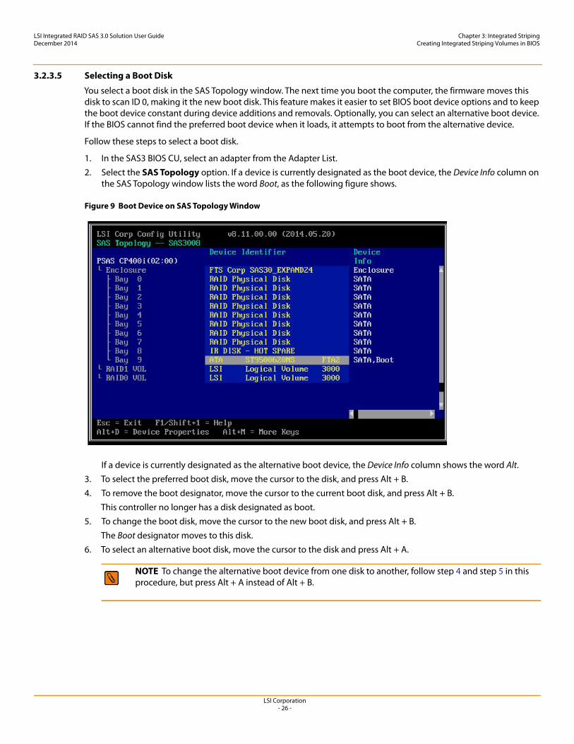
3.2.3.5 Selecting a Boot Disk
You select a boot disk in the SAS Topology window. The next time you boot the computer, the firmware moves this disk to scan ID 0, making it the new boot disk. This feature makes it easier to set BIOS boot device options and to keep the boot device constant during device additions and removals. Optionally, you can select an alternative boot device. If the BIOS cannot find the preferred boot device when it loads, it attempts to boot from the alternative device.
Follow these steps to select a boot disk.
1. In the SAS3 BIOS CU, select an adapter from the Adapter List.2. Select the SAS Topology option. If a device is currently designated as the boot device, the Device Info column on
the SAS Topology window lists the word Boot, as the following figure shows.
Figure 9 Boot Device on SAS Topology Window
If a device is currently designated as the alternative boot device, the Device Info column shows the word Alt.3. To select the preferred boot disk, move the cursor to the disk, and press Alt + B.4. To remove the boot designator, move the cursor to the current boot disk, and press Alt + B.
This controller no longer has a disk designated as boot.5. To change the boot disk, move the cursor to the new boot disk, and press Alt + B.
The Boot designator moves to this disk.6. To select an alternative boot disk, move the cursor to the disk and press Alt + A.
NOTE To change the alternative boot device from one disk to another, follow step 4 and step 5 in this procedure, but press Alt + A instead of Alt + B.
LSI Corporation- 27 -
LSI Integrated RAID SAS 3.0 Solution User GuideDecember 2014
Chapter 4: Human Interface Infrastructure Configuration ApplicationIntroduction
Chapter 4: Human Interface Infrastructure Configuration Application
4.1 Introduction
4.1.1 Overview
The Human Interface Infrastructure (HII) Configuration Application is a tool used to configure controllers, physical disks, and virtual disks, and to perform other configuration tasks in a pre-boot, Unified Extensible Firmware Interface (UEFI) environment. This document explains how to use the HII interface to perform these tasks.
4.1.2 Controller Support
The HII Configuration Application supports the following Avago SAS-2 and SAS-3 controllers, running IT or IR firmware, and the host bus adapters based on the following controllers.
LSISAS3004 LSISAS3008
NOTE Different versions of the HII Configuration Application firmware exist for integrated RAID (IR) systems and initiator-target (IT) systems. The Firmware Type property on the View Controller Properties window indicates which version is running.The IR version of the HII Configuration Application is documented in Section 4.3, Using the Integrated RAID Version. This version lets you view system information, create virtual disks (RAID volumes), and perform other management tasks on controllers, physical disks, and virtual disks.
NOTE The HII Configuration Application displays only the logical unit number (LUN) zero devices. It does not display the LUN nonzero devices discovered by the boot services driver (BSD). This behavior is consistent with the Configuration Utility (CU) provided by the LSI® Legacy (Int13) basic input/output system (BIOS).
LSI Corporation- 28 -
LSI Integrated RAID SAS 3.0 Solution User GuideDecember 2014
Chapter 4: Human Interface Infrastructure Configuration ApplicationStarting the Configuration Application Interface
4.2 Starting the Configuration Application Interface
Follow these steps to start the HII Configuration Application and to access the main configuration menu.
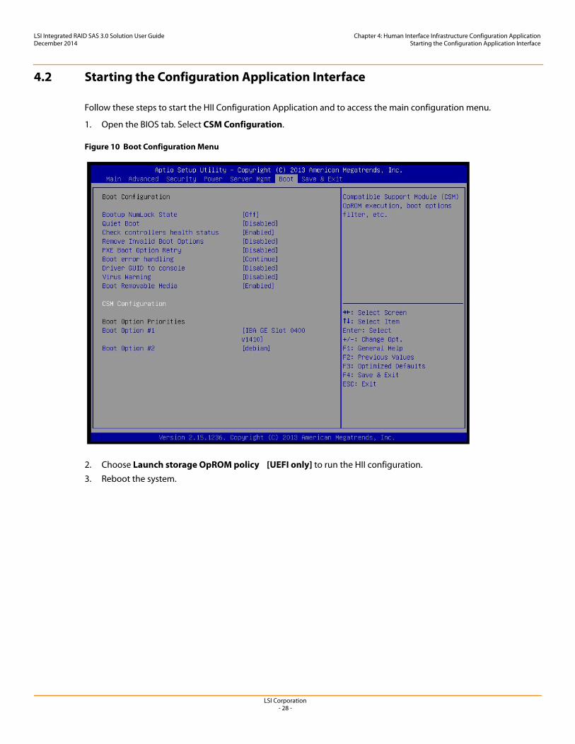
1. Open the BIOS tab. Select CSM Configuration.
Figure 10 Boot Configuration Menu
2. Choose Launch storage OpROM policy [UEFI only] to run the HII configuration.3. Reboot the system.
LSI Corporation- 29 -
LSI Integrated RAID SAS 3.0 Solution User GuideDecember 2014
Chapter 4: Human Interface Infrastructure Configuration ApplicationStarting the Configuration Application Interface
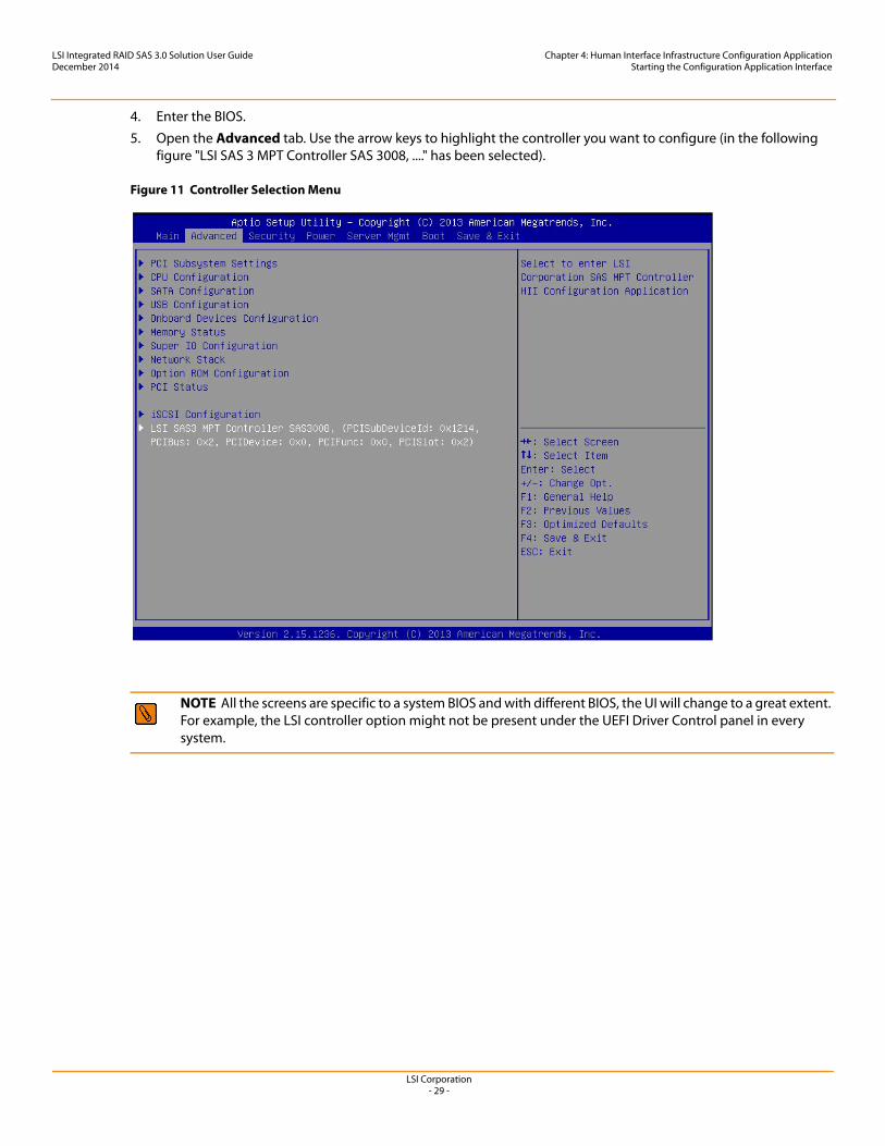
4. Enter the BIOS.5. Open the Advanced tab. Use the arrow keys to highlight the controller you want to configure (in the following
figure "LSI SAS 3 MPT Controller SAS 3008, ...." has been selected).
Figure 11 Controller Selection Menu
NOTE All the screens are specific to a system BIOS and with different BIOS, the UI will change to a great extent.For example, the LSI controller option might not be present under the UEFI Driver Control panel in every system.
LSI Corporation- 30 -
LSI Integrated RAID SAS 3.0 Solution User GuideDecember 2014
Chapter 4: Human Interface Infrastructure Configuration ApplicationStarting the Configuration Application Interface
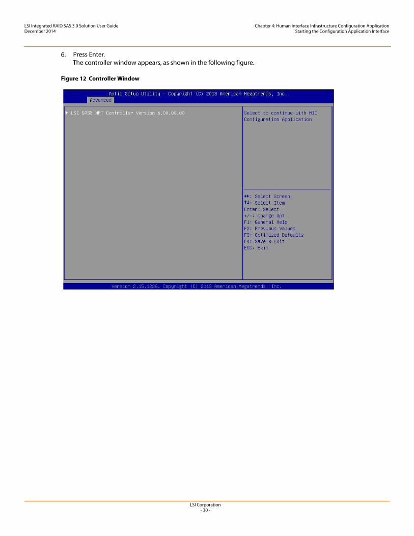
6. Press Enter.The controller window appears, as shown in the following figure.
Figure 12 Controller Window
LSI Corporation- 31 -
LSI Integrated RAID SAS 3.0 Solution User GuideDecember 2014
Chapter 4: Human Interface Infrastructure Configuration ApplicationStarting the Configuration Application Interface
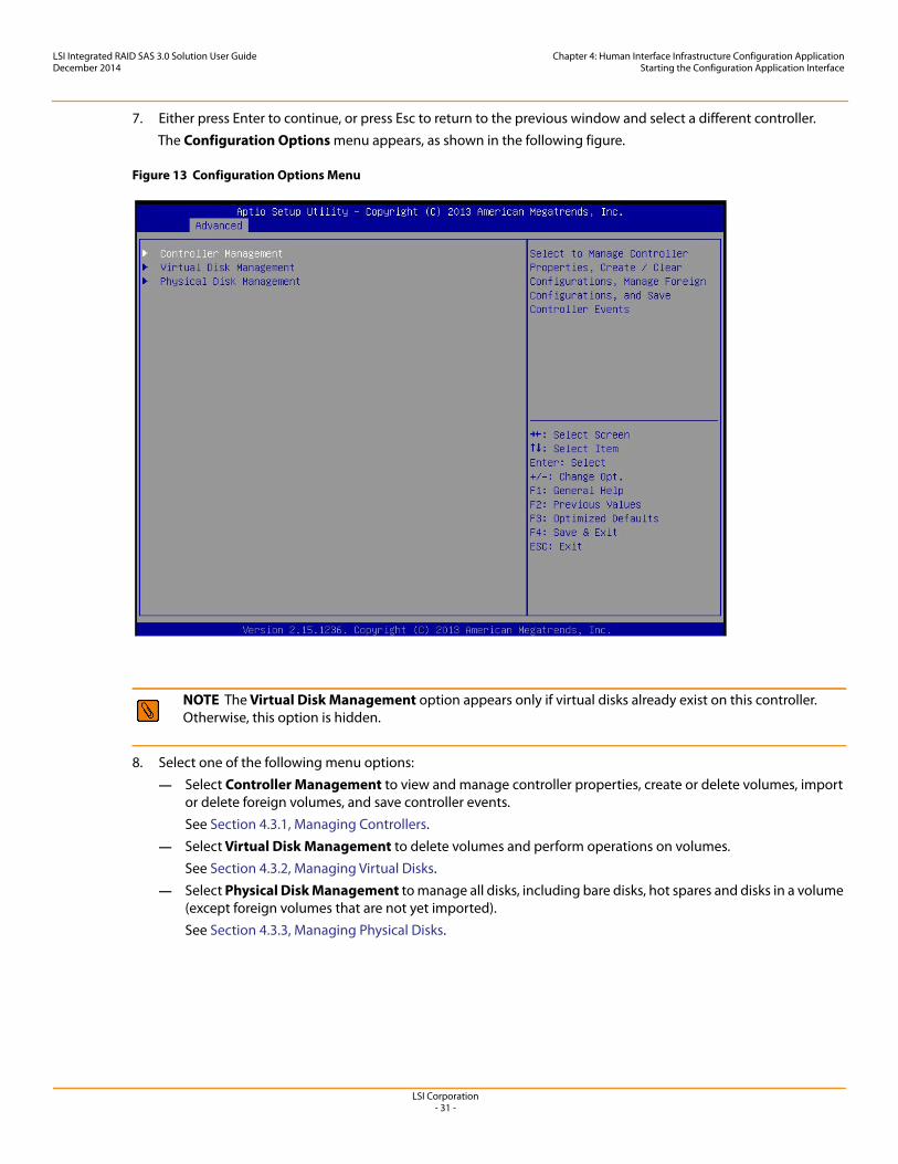
7. Either press Enter to continue, or press Esc to return to the previous window and select a different controller. The Configuration Options menu appears, as shown in the following figure.
Figure 13 Configuration Options Menu
8. Select one of the following menu options:— Select Controller Management to view and manage controller properties, create or delete volumes, import
or delete foreign volumes, and save controller events. See Section 4.3.1, Managing Controllers.
— Select Virtual Disk Management to delete volumes and perform operations on volumes. See Section 4.3.2, Managing Virtual Disks.
— Select Physical Disk Management to manage all disks, including bare disks, hot spares and disks in a volume (except foreign volumes that are not yet imported). See Section 4.3.3, Managing Physical Disks.
NOTE The Virtual Disk Management option appears only if virtual disks already exist on this controller. Otherwise, this option is hidden.
LSI Corporation- 32 -
LSI Integrated RAID SAS 3.0 Solution User GuideDecember 2014
Chapter 4: Human Interface Infrastructure Configuration ApplicationUsing the Integrated RAID Version
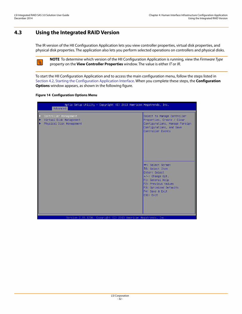
4.3 Using the Integrated RAID Version
The IR version of the HII Configuration Application lets you view controller properties, virtual disk properties, and physical disk properties. The application also lets you perform selected operations on controllers and physical disks.
To start the HII Configuration Application and to access the main configuration menu, follow the steps listed in Section 4.2, Starting the Configuration Application Interface. When you complete these steps, the Configuration Options window appears, as shown in the following figure.
Figure 14 Configuration Options Menu
NOTE To determine which version of the HII Configuration Application is running, view the Firmware Type property on the View Controller Properties window. The value is either IT or IR.
LSI Corporation- 33 -
LSI Integrated RAID SAS 3.0 Solution User GuideDecember 2014
Chapter 4: Human Interface Infrastructure Configuration ApplicationUsing the Integrated RAID Version
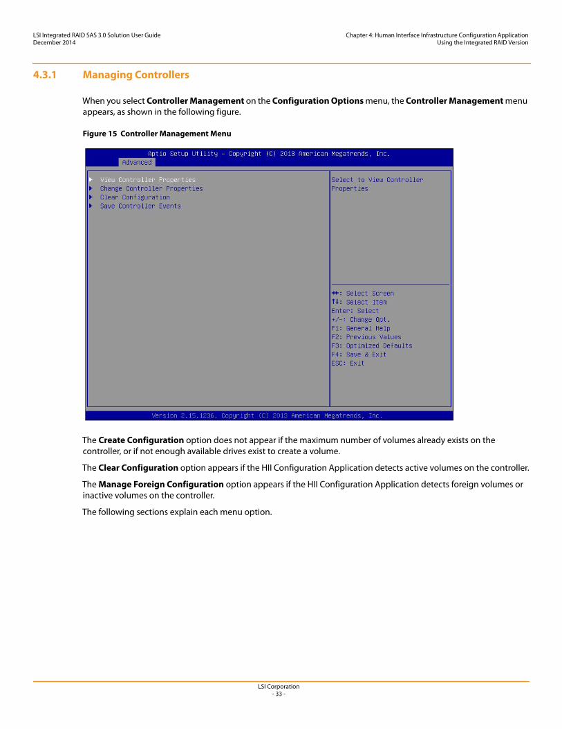
4.3.1 Managing Controllers
When you select Controller Management on the Configuration Options menu, the Controller Management menu appears, as shown in the following figure.
Figure 15 Controller Management Menu
The Create Configuration option does not appear if the maximum number of volumes already exists on the controller, or if not enough available drives exist to create a volume.
The Clear Configuration option appears if the HII Configuration Application detects active volumes on the controller.
The Manage Foreign Configuration option appears if the HII Configuration Application detects foreign volumes or inactive volumes on the controller.
The following sections explain each menu option.
LSI Corporation- 34 -
LSI Integrated RAID SAS 3.0 Solution User GuideDecember 2014
Chapter 4: Human Interface Infrastructure Configuration ApplicationUsing the Integrated RAID Version
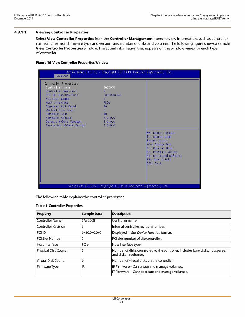
4.3.1.1 Viewing Controller Properties
Select View Controller Properties from the Controller Management menu to view information, such as controller name and revision, firmware type and version, and number of disks and volumes. The following figure shows a sample View Controller Properties window. The actual information that appears on the window varies for each type of controller.
Figure 16 View Controller Properties Window
The following table explains the controller properties.
Table 1 Controller Properties
Property Sample Data Description
Controller Name SAS2008 Controller name.
Controller Revision 3 Internal controller revision number.
PCI ID 0x20:0x0:0x0 Displayed in Bus:Device:Function format.
PCI Slot Number 5 PCI slot number of the controller.
Host Interface PCIe Host interface type.
Physical Disk Count 3 Number of disks connected to the controller. Includes bare disks, hot spares, and disks in volumes.
Virtual Disk Count 0 Number of virtual disks on the controller.
Firmware Type IR IR Firmware – Can create and manage volumes.IT Firmware – Cannot create and manage volumes.
LSI Corporation- 35 -
LSI Integrated RAID SAS 3.0 Solution User GuideDecember 2014
Chapter 4: Human Interface Infrastructure Configuration ApplicationUsing the Integrated RAID Version
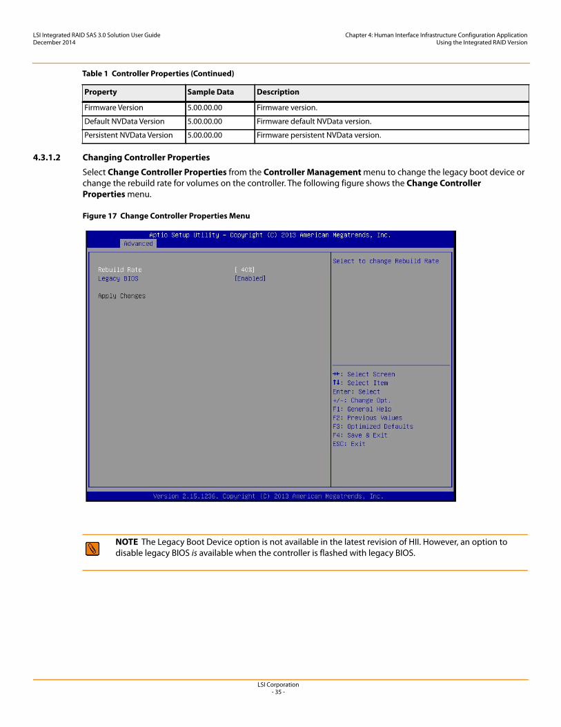
4.3.1.2 Changing Controller Properties
Select Change Controller Properties from the Controller Management menu to change the legacy boot device or change the rebuild rate for volumes on the controller. The following figure shows the Change Controller Properties menu.
Figure 17 Change Controller Properties Menu
Firmware Version 5.00.00.00 Firmware version.
Default NVData Version 5.00.00.00 Firmware default NVData version.
Persistent NVData Version 5.00.00.00 Firmware persistent NVData version.
NOTE The Legacy Boot Device option is not available in the latest revision of HII. However, an option to disable legacy BIOS is available when the controller is flashed with legacy BIOS.
Table 1 Controller Properties (Continued)
Property Sample Data Description
LSI Corporation- 36 -
LSI Integrated RAID SAS 3.0 Solution User GuideDecember 2014
Chapter 4: Human Interface Infrastructure Configuration ApplicationUsing the Integrated RAID Version
4.3.1.2.1 Rebuild Rate
The rebuild rate is the percentage of the compute cycles dedicated to rebuilding failed drives in volumes on this controller. The rebuild rate can be configured between 0 percent and 100 percent. At 0 percent, the rebuild runs only if the firmware is not performing other functions. At 100 percent, the rebuild has a higher priority than any other firmware activity.
Follow these steps to change the rebuild rate for volumes on this controller.
1. Highlight Rebuild Rate from the pop-up menu and press Enter.2. Select the desired rebuild rate and press Enter.3. Highlight Apply Changes and press Enter to change the rebuild rate.
4.3.1.3 Creating a Configuration
Select Create Configuration from the Controller Management menu to create a RAID 0 or RAID 1 volume on the selected controller.
RAID 0 provides disk striping across all drives in the RAID volume. RAID 0 volumes provide very high I/O performance but does not provide any data redundancy. RAID 0 volumes can have from two to ten disk drives.
RAID 1 volumes duplicate all data from one drive to another drive in the volume. RAID 1 volumes provide data redundancy. RAID 1 volumes have two mirrored disk drives, plus one or two optional hot spare drives.
NOTE Using a 0 percent or 100 percent rebuild rate is not recommended. The default rebuild rate is 50 percent.
LSI Corporation- 37 -
LSI Integrated RAID SAS 3.0 Solution User GuideDecember 2014
Chapter 4: Human Interface Infrastructure Configuration ApplicationUsing the Integrated RAID Version
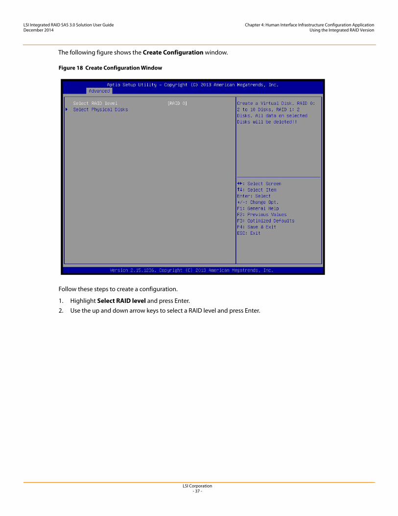
The following figure shows the Create Configuration window.
Figure 18 Create Configuration Window
Follow these steps to create a configuration.
1. Highlight Select RAID level and press Enter.2. Use the up and down arrow keys to select a RAID level and press Enter.
LSI Corporation- 38 -
LSI Integrated RAID SAS 3.0 Solution User GuideDecember 2014
Chapter 4: Human Interface Infrastructure Configuration ApplicationUsing the Integrated RAID Version
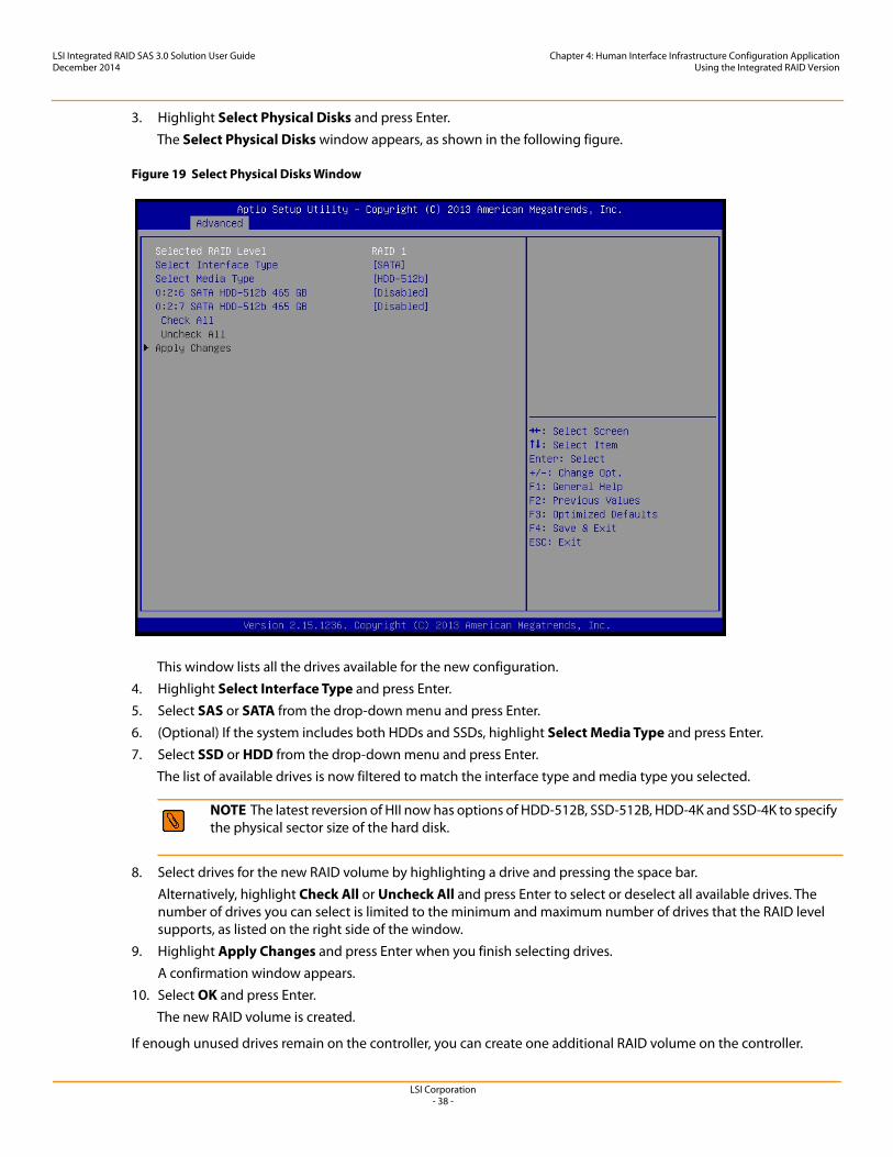
3. Highlight Select Physical Disks and press Enter.The Select Physical Disks window appears, as shown in the following figure.
Figure 19 Select Physical Disks Window
This window lists all the drives available for the new configuration. 4. Highlight Select Interface Type and press Enter.5. Select SAS or SATA from the drop-down menu and press Enter.6. (Optional) If the system includes both HDDs and SSDs, highlight Select Media Type and press Enter.7. Select SSD or HDD from the drop-down menu and press Enter.
The list of available drives is now filtered to match the interface type and media type you selected.
8. Select drives for the new RAID volume by highlighting a drive and pressing the space bar. Alternatively, highlight Check All or Uncheck All and press Enter to select or deselect all available drives. The number of drives you can select is limited to the minimum and maximum number of drives that the RAID level supports, as listed on the right side of the window.
9. Highlight Apply Changes and press Enter when you finish selecting drives. A confirmation window appears.
10. Select OK and press Enter.The new RAID volume is created.
If enough unused drives remain on the controller, you can create one additional RAID volume on the controller.
NOTE The latest reversion of HII now has options of HDD-512B, SSD-512B, HDD-4K and SSD-4K to specify the physical sector size of the hard disk.
LSI Corporation- 39 -
LSI Integrated RAID SAS 3.0 Solution User GuideDecember 2014
Chapter 4: Human Interface Infrastructure Configuration ApplicationUsing the Integrated RAID Version
4.3.1.4 Clearing a Configuration
Select Clear Configuration from the Controller Management menu to delete all existing RAID volumes from the controller. The following figure shows the Warning window that appears when you select Clear Configuration.
Figure 20 Clear Configuration Confirmation Window
Follow these steps to clear a configuration.
1. Press the space bar to select the confirmation option in the brackets.2. Highlight Yes and press Enter.
All existing configurations are cleared from the controller.
4.3.1.5 Managing a Foreign Configuration
Select Manage Foreign Configuration from the Controller Management menu to import or delete a foreign (inactive) volume.
CAUTION Possible data loss – When you clear a configuration, all data is deleted from the disks in the configuration. Back up all data that you want to keep before you use this command.
NOTE A foreign configuration is a RAID volume that was created on another controller, and whose member drives have been moved to this controller. You can have up to two volumes on a single controller, which includes foreign configurations and configurations that you create on the controller with the HII Configuration Application.
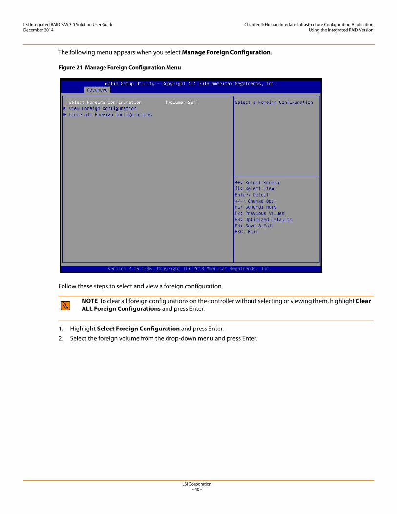
LSI Corporation- 40 -
LSI Integrated RAID SAS 3.0 Solution User GuideDecember 2014
Chapter 4: Human Interface Infrastructure Configuration ApplicationUsing the Integrated RAID Version
The following menu appears when you select Manage Foreign Configuration.
Figure 21 Manage Foreign Configuration Menu
Follow these steps to select and view a foreign configuration.
1. Highlight Select Foreign Configuration and press Enter.2. Select the foreign volume from the drop-down menu and press Enter.
NOTE To clear all foreign configurations on the controller without selecting or viewing them, highlight Clear ALL Foreign Configurations and press Enter.
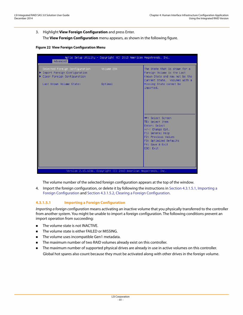
LSI Corporation- 41 -
LSI Integrated RAID SAS 3.0 Solution User GuideDecember 2014
Chapter 4: Human Interface Infrastructure Configuration ApplicationUsing the Integrated RAID Version
3. Highlight View Foreign Configuration and press Enter.The View Foreign Configuration menu appears, as shown in the following figure.
Figure 22 View Foreign Configuration Menu
The volume number of the selected foreign configuration appears at the top of the window.4. Import the foreign configuration, or delete it by following the instructions in Section 4.3.1.5.1, Importing a
Foreign Configuration and Section 4.3.1.5.2, Clearing a Foreign Configuration.
4.3.1.5.1 Importing a Foreign Configuration
Importing a foreign configuration means activating an inactive volume that you physically transferred to the controller from another system. You might be unable to import a foreign configuration. The following conditions prevent an import operation from succeeding:
The volume state is not INACTIVE. The volume state is either FAILED or MISSING. The volume uses incompatible Gen1 metadata. The maximum number of two RAID volumes already exist on this controller. The maximum number of supported physical drives are already in use in active volumes on this controller.
Global hot spares also count because they must be activated along with other drives in the foreign volume.
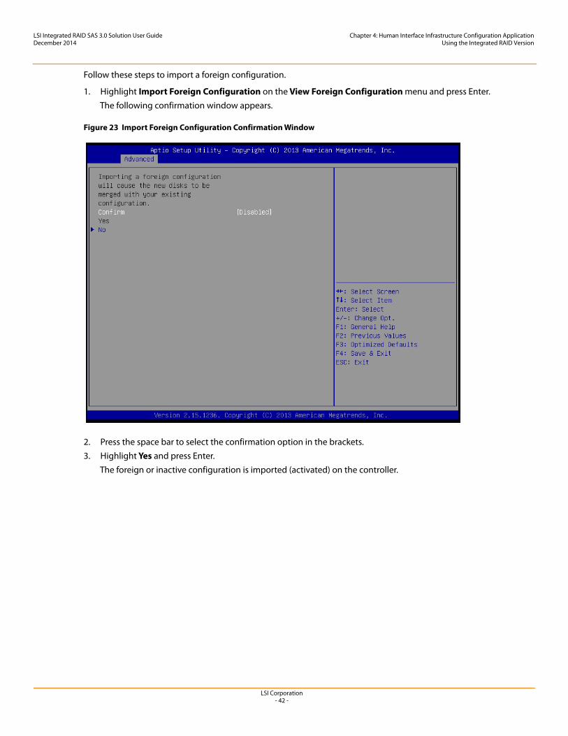
LSI Corporation- 42 -
LSI Integrated RAID SAS 3.0 Solution User GuideDecember 2014
Chapter 4: Human Interface Infrastructure Configuration ApplicationUsing the Integrated RAID Version
Follow these steps to import a foreign configuration.
1. Highlight Import Foreign Configuration on the View Foreign Configuration menu and press Enter.The following confirmation window appears.
Figure 23 Import Foreign Configuration Confirmation Window
2. Press the space bar to select the confirmation option in the brackets.3. Highlight Yes and press Enter.
The foreign or inactive configuration is imported (activated) on the controller.
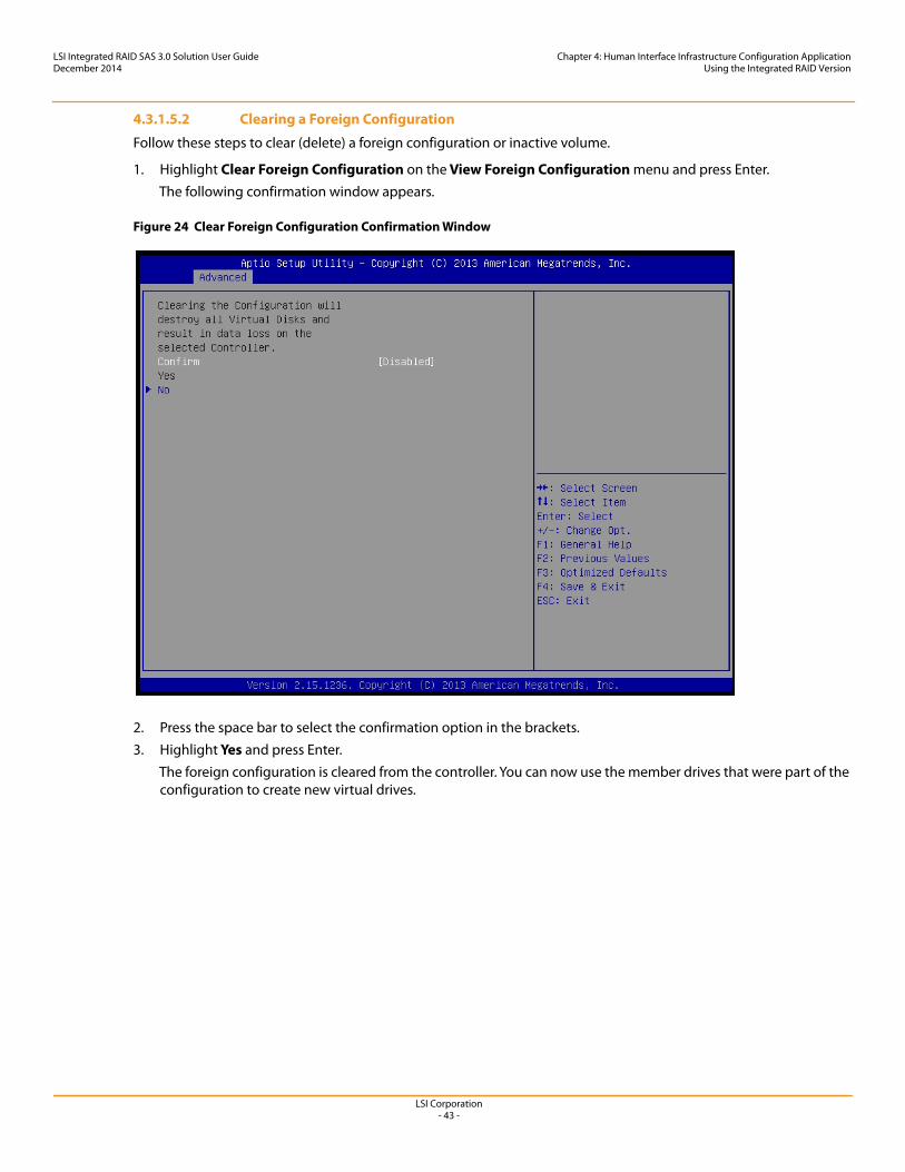
LSI Corporation- 43 -
LSI Integrated RAID SAS 3.0 Solution User GuideDecember 2014
Chapter 4: Human Interface Infrastructure Configuration ApplicationUsing the Integrated RAID Version
4.3.1.5.2 Clearing a Foreign Configuration
Follow these steps to clear (delete) a foreign configuration or inactive volume.
1. Highlight Clear Foreign Configuration on the View Foreign Configuration menu and press Enter.The following confirmation window appears.
Figure 24 Clear Foreign Configuration Confirmation Window
2. Press the space bar to select the confirmation option in the brackets.3. Highlight Yes and press Enter.
The foreign configuration is cleared from the controller. You can now use the member drives that were part of the configuration to create new virtual drives.
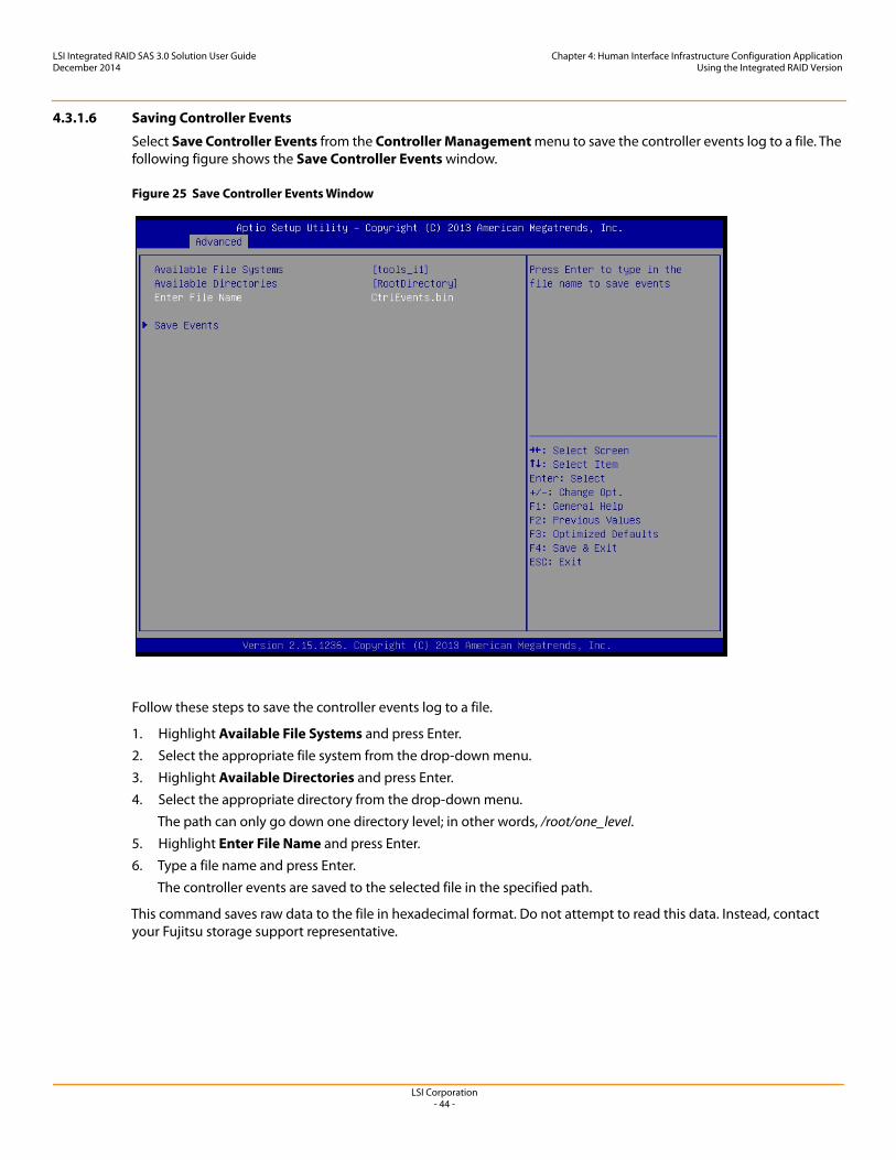
LSI Corporation- 44 -
LSI Integrated RAID SAS 3.0 Solution User GuideDecember 2014
Chapter 4: Human Interface Infrastructure Configuration ApplicationUsing the Integrated RAID Version
4.3.1.6 Saving Controller Events
Select Save Controller Events from the Controller Management menu to save the controller events log to a file. The following figure shows the Save Controller Events window.
Figure 25 Save Controller Events Window
Follow these steps to save the controller events log to a file.
1. Highlight Available File Systems and press Enter.2. Select the appropriate file system from the drop-down menu.3. Highlight Available Directories and press Enter.4. Select the appropriate directory from the drop-down menu.
The path can only go down one directory level; in other words, /root/one_level.5. Highlight Enter File Name and press Enter.6. Type a file name and press Enter.
The controller events are saved to the selected file in the specified path.
This command saves raw data to the file in hexadecimal format. Do not attempt to read this data. Instead, contact your Fujitsu storage support representative.
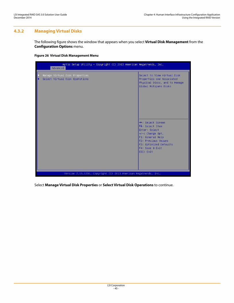
LSI Corporation- 45 -
LSI Integrated RAID SAS 3.0 Solution User GuideDecember 2014
Chapter 4: Human Interface Infrastructure Configuration ApplicationUsing the Integrated RAID Version
4.3.2 Managing Virtual Disks
The following figure shows the window that appears when you select Virtual Disk Management from the Configuration Options menu.
Figure 26 Virtual Disk Management Menu
Select Manage Virtual Disk Properties or Select Virtual Disk Operations to continue.
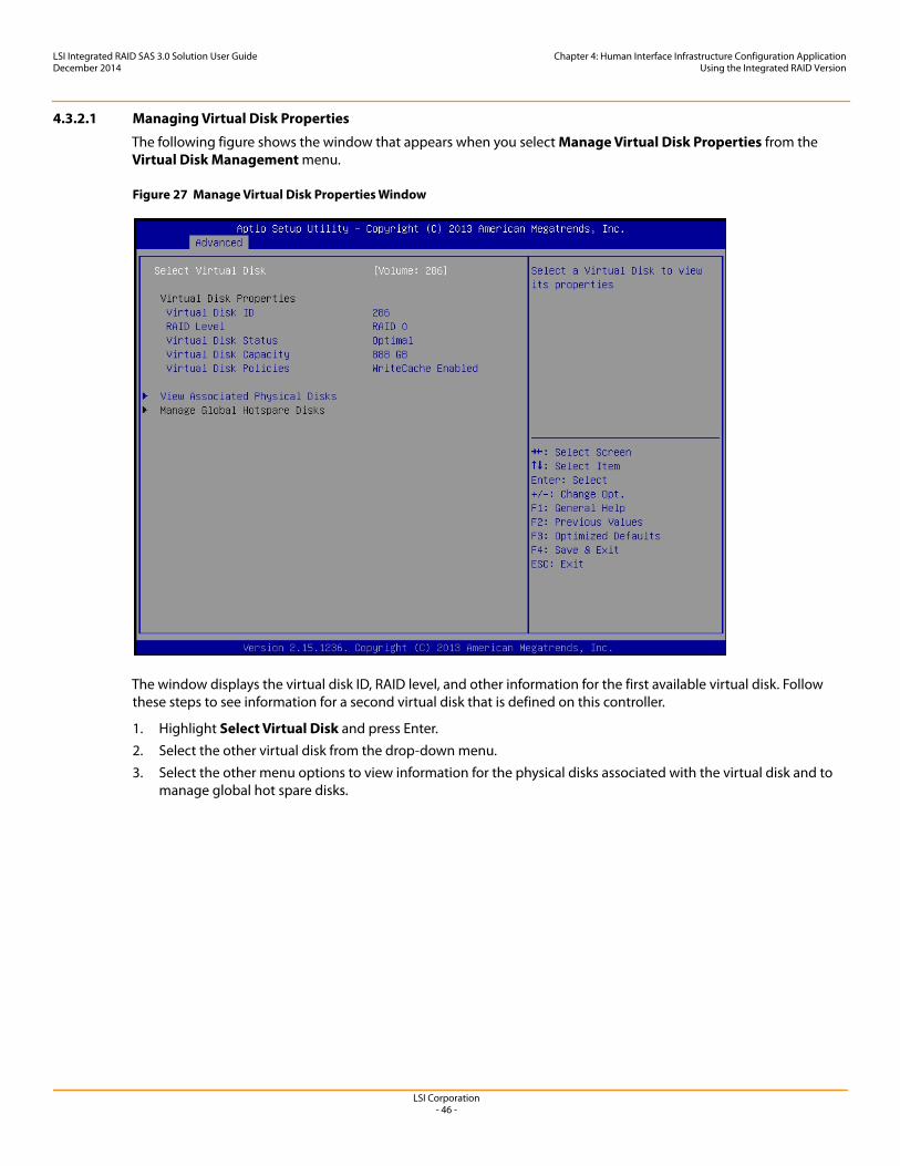
LSI Corporation- 46 -
LSI Integrated RAID SAS 3.0 Solution User GuideDecember 2014
Chapter 4: Human Interface Infrastructure Configuration ApplicationUsing the Integrated RAID Version
4.3.2.1 Managing Virtual Disk Properties
The following figure shows the window that appears when you select Manage Virtual Disk Properties from the Virtual Disk Management menu.
Figure 27 Manage Virtual Disk Properties Window
The window displays the virtual disk ID, RAID level, and other information for the first available virtual disk. Follow these steps to see information for a second virtual disk that is defined on this controller.
1. Highlight Select Virtual Disk and press Enter. 2. Select the other virtual disk from the drop-down menu.3. Select the other menu options to view information for the physical disks associated with the virtual disk and to
manage global hot spare disks.
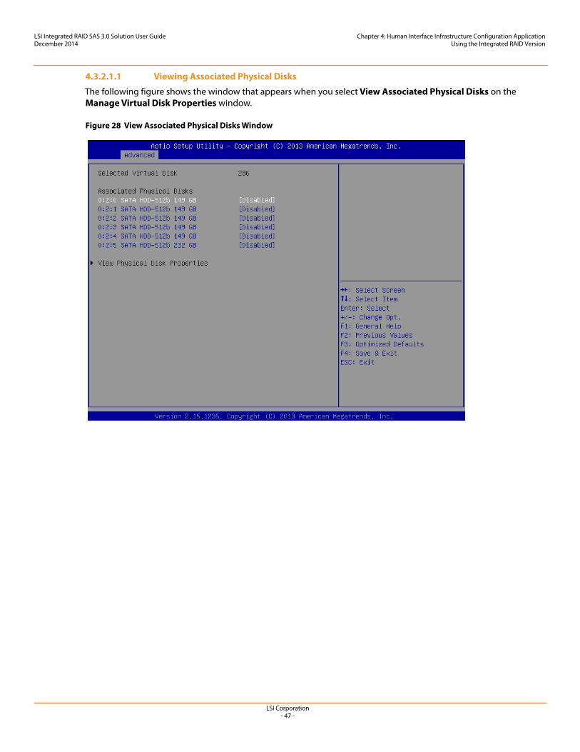
LSI Corporation- 47 -
LSI Integrated RAID SAS 3.0 Solution User GuideDecember 2014
Chapter 4: Human Interface Infrastructure Configuration ApplicationUsing the Integrated RAID Version
4.3.2.1.1 Viewing Associated Physical Disks
The following figure shows the window that appears when you select View Associated Physical Disks on the Manage Virtual Disk Properties window.
Figure 28 View Associated Physical Disks Window
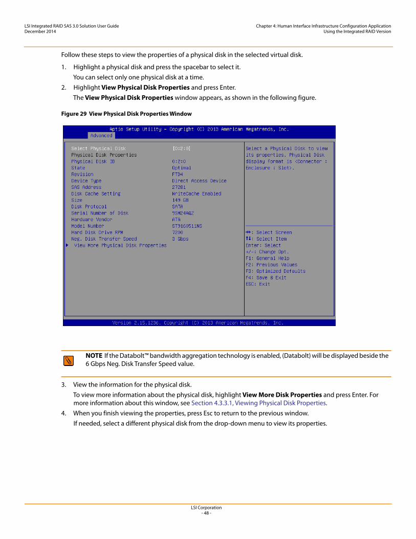
LSI Corporation- 48 -
LSI Integrated RAID SAS 3.0 Solution User GuideDecember 2014
Chapter 4: Human Interface Infrastructure Configuration ApplicationUsing the Integrated RAID Version
Follow these steps to view the properties of a physical disk in the selected virtual disk.
1. Highlight a physical disk and press the spacebar to select it.You can select only one physical disk at a time.
2. Highlight View Physical Disk Properties and press Enter.The View Physical Disk Properties window appears, as shown in the following figure.
Figure 29 View Physical Disk Properties Window
3. View the information for the physical disk.To view more information about the physical disk, highlight View More Disk Properties and press Enter. For more information about this window, see Section 4.3.3.1, Viewing Physical Disk Properties.
4. When you finish viewing the properties, press Esc to return to the previous window.If needed, select a different physical disk from the drop-down menu to view its properties.
NOTE If the Databolt™ bandwidth aggregation technology is enabled, (Databolt) will be displayed beside the 6 Gbps Neg. Disk Transfer Speed value.
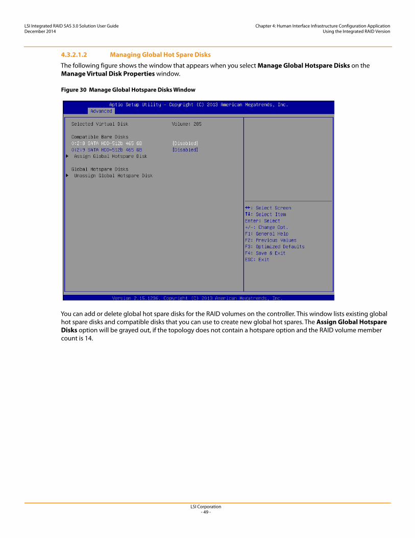
LSI Corporation- 49 -
LSI Integrated RAID SAS 3.0 Solution User GuideDecember 2014
Chapter 4: Human Interface Infrastructure Configuration ApplicationUsing the Integrated RAID Version
4.3.2.1.2 Managing Global Hot Spare Disks
The following figure shows the window that appears when you select Manage Global Hotspare Disks on the Manage Virtual Disk Properties window.
Figure 30 Manage Global Hotspare Disks Window
You can add or delete global hot spare disks for the RAID volumes on the controller. This window lists existing global hot spare disks and compatible disks that you can use to create new global hot spares. The Assign Global Hotspare Disks option will be grayed out, if the topology does not contain a hotspare option and the RAID volume member count is 14.
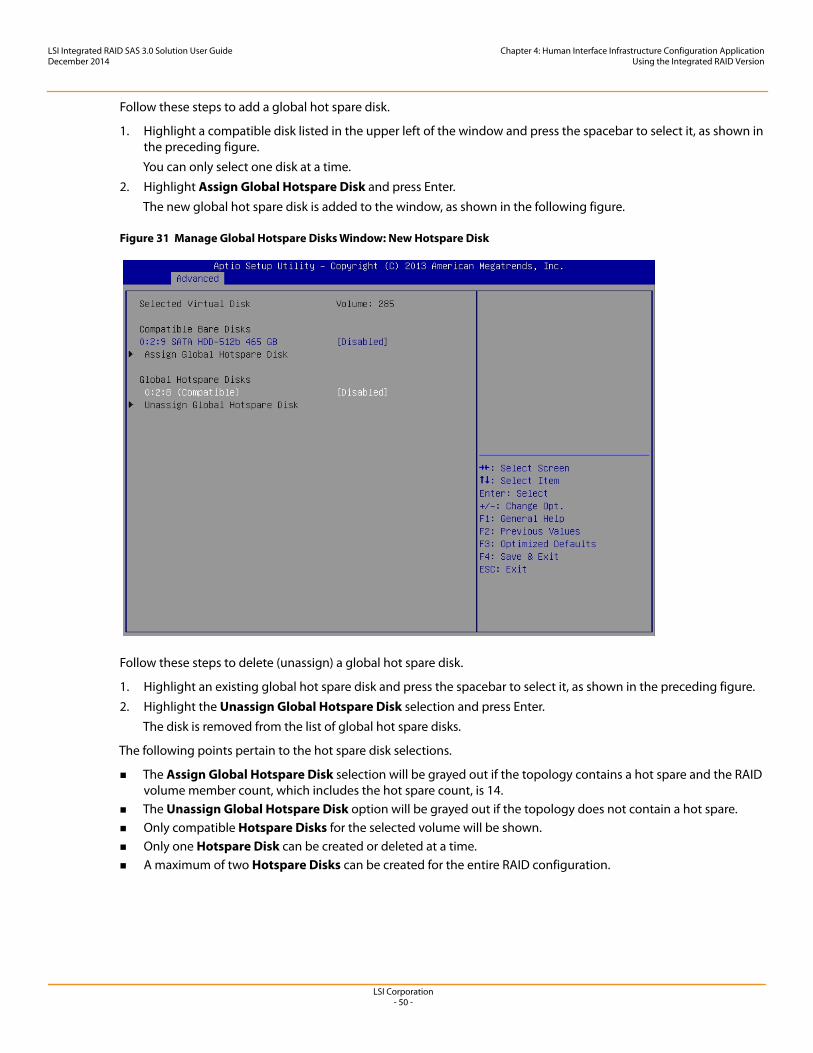
LSI Corporation- 50 -
LSI Integrated RAID SAS 3.0 Solution User GuideDecember 2014
Chapter 4: Human Interface Infrastructure Configuration ApplicationUsing the Integrated RAID Version
Follow these steps to add a global hot spare disk.
1. Highlight a compatible disk listed in the upper left of the window and press the spacebar to select it, as shown in the preceding figure.You can only select one disk at a time.
2. Highlight Assign Global Hotspare Disk and press Enter.The new global hot spare disk is added to the window, as shown in the following figure.
Figure 31 Manage Global Hotspare Disks Window: New Hotspare Disk
Follow these steps to delete (unassign) a global hot spare disk.
1. Highlight an existing global hot spare disk and press the spacebar to select it, as shown in the preceding figure.2. Highlight the Unassign Global Hotspare Disk selection and press Enter.
The disk is removed from the list of global hot spare disks.
The following points pertain to the hot spare disk selections.
The Assign Global Hotspare Disk selection will be grayed out if the topology contains a hot spare and the RAID volume member count, which includes the hot spare count, is 14.
The Unassign Global Hotspare Disk option will be grayed out if the topology does not contain a hot spare. Only compatible Hotspare Disks for the selected volume will be shown. Only one Hotspare Disk can be created or deleted at a time. A maximum of two Hotspare Disks can be created for the entire RAID configuration.
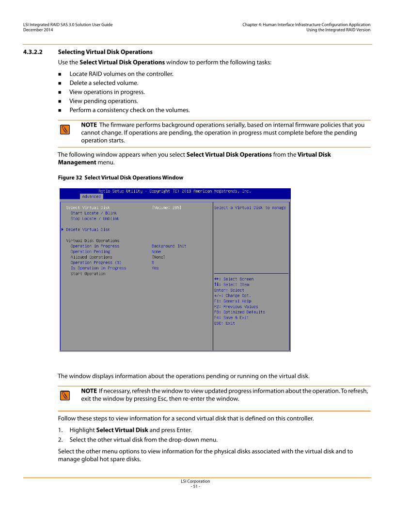
LSI Corporation- 51 -
LSI Integrated RAID SAS 3.0 Solution User GuideDecember 2014
Chapter 4: Human Interface Infrastructure Configuration ApplicationUsing the Integrated RAID Version
4.3.2.2 Selecting Virtual Disk Operations
Use the Select Virtual Disk Operations window to perform the following tasks:
Locate RAID volumes on the controller. Delete a selected volume. View operations in progress. View pending operations. Perform a consistency check on the volumes.
The following window appears when you select Select Virtual Disk Operations from the Virtual Disk Management menu.
Figure 32 Select Virtual Disk Operations Window
The window displays information about the operations pending or running on the virtual disk.
Follow these steps to view information for a second virtual disk that is defined on this controller.
1. Highlight Select Virtual Disk and press Enter. 2. Select the other virtual disk from the drop-down menu.
Select the other menu options to view information for the physical disks associated with the virtual disk and to manage global hot spare disks.
NOTE The firmware performs background operations serially, based on internal firmware policies that you cannot change. If operations are pending, the operation in progress must complete before the pending operation starts.
NOTE If necessary, refresh the window to view updated progress information about the operation. To refresh, exit the window by pressing Esc, then re-enter the window.
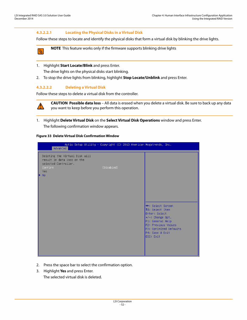
LSI Corporation- 52 -
LSI Integrated RAID SAS 3.0 Solution User GuideDecember 2014
Chapter 4: Human Interface Infrastructure Configuration ApplicationUsing the Integrated RAID Version
4.3.2.2.1 Locating the Physical Disks in a Virtual Disk
Follow these steps to locate and identify the physical disks that form a virtual disk by blinking the drive lights.
1. Highlight Start Locate/Blink and press Enter.The drive lights on the physical disks start blinking.
2. To stop the drive lights from blinking, highlight Stop Locate/Unblink and press Enter.
4.3.2.2.2 Deleting a Virtual Disk
Follow these steps to delete a virtual disk from the controller.
1. Highlight Delete Virtual Disk on the Select Virtual Disk Operations window and press Enter.The following confirmation window appears.
Figure 33 Delete Virtual Disk Confirmation Window
2. Press the space bar to select the confirmation option.3. Highlight Yes and press Enter.
The selected virtual disk is deleted.
NOTE This feature works only if the firmware supports blinking drive lights
CAUTION Possible data loss – All data is erased when you delete a virtual disk. Be sure to back up any data you want to keep before you perform this operation.
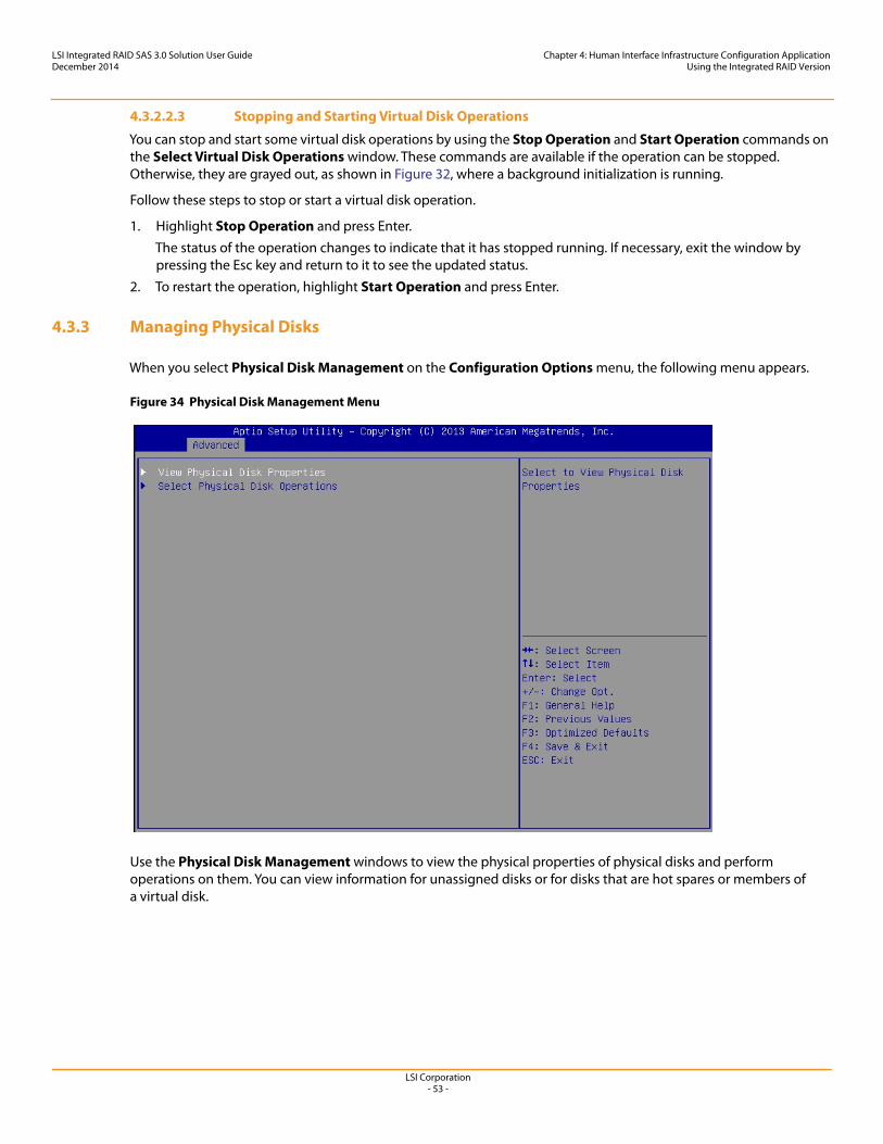
LSI Corporation- 53 -
LSI Integrated RAID SAS 3.0 Solution User GuideDecember 2014
Chapter 4: Human Interface Infrastructure Configuration ApplicationUsing the Integrated RAID Version
4.3.2.2.3 Stopping and Starting Virtual Disk Operations
You can stop and start some virtual disk operations by using the Stop Operation and Start Operation commands on the Select Virtual Disk Operations window. These commands are available if the operation can be stopped. Otherwise, they are grayed out, as shown in Figure 32, where a background initialization is running.
Follow these steps to stop or start a virtual disk operation.
1. Highlight Stop Operation and press Enter.The status of the operation changes to indicate that it has stopped running. If necessary, exit the window by pressing the Esc key and return to it to see the updated status.
2. To restart the operation, highlight Start Operation and press Enter.
4.3.3 Managing Physical Disks
When you select Physical Disk Management on the Configuration Options menu, the following menu appears.
Figure 34 Physical Disk Management Menu
Use the Physical Disk Management windows to view the physical properties of physical disks and perform operations on them. You can view information for unassigned disks or for disks that are hot spares or members of a virtual disk.
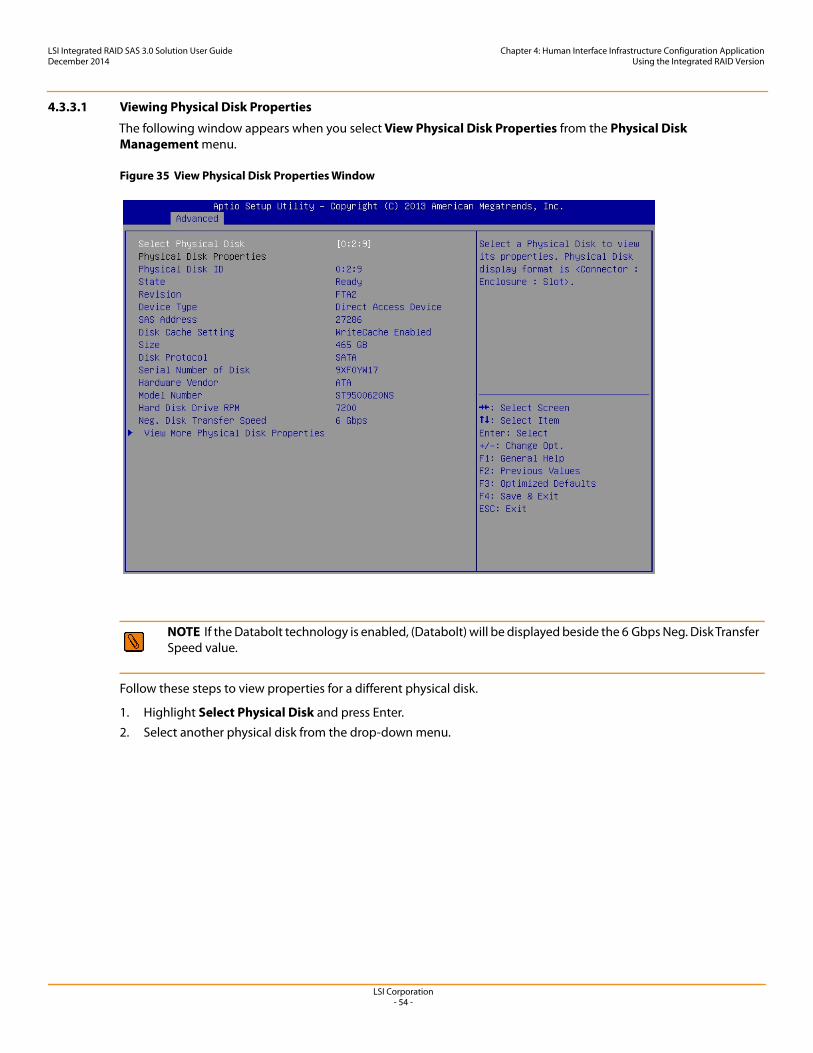
LSI Corporation- 54 -
LSI Integrated RAID SAS 3.0 Solution User GuideDecember 2014
Chapter 4: Human Interface Infrastructure Configuration ApplicationUsing the Integrated RAID Version
4.3.3.1 Viewing Physical Disk Properties
The following window appears when you select View Physical Disk Properties from the Physical Disk Management menu.
Figure 35 View Physical Disk Properties Window
Follow these steps to view properties for a different physical disk.
1. Highlight Select Physical Disk and press Enter. 2. Select another physical disk from the drop-down menu.
NOTE If the Databolt technology is enabled, (Databolt) will be displayed beside the 6 Gbps Neg. Disk Transfer Speed value.
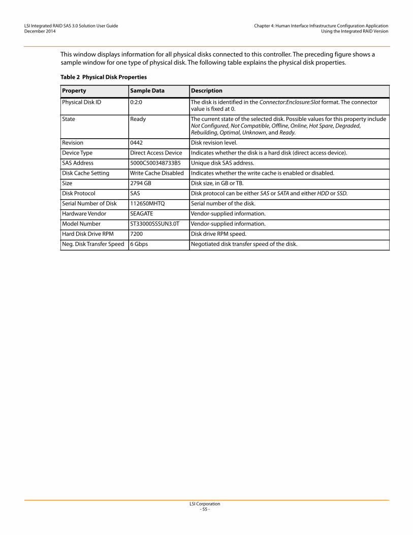
LSI Corporation- 55 -
LSI Integrated RAID SAS 3.0 Solution User GuideDecember 2014
Chapter 4: Human Interface Infrastructure Configuration ApplicationUsing the Integrated RAID Version
This window displays information for all physical disks connected to this controller. The preceding figure shows a sample window for one type of physical disk. The following table explains the physical disk properties.
Table 2 Physical Disk Properties
Property Sample Data Description
Physical Disk ID 0:2:0 The disk is identified in the Connector:Enclosure:Slot format. The connector value is fixed at 0.
State Ready The current state of the selected disk. Possible values for this property include Not Configured, Not Compatible, Offline, Online, Hot Spare, Degraded, Rebuilding, Optimal, Unknown, and Ready.
Revision 0442 Disk revision level.
Device Type Direct Access Device Indicates whether the disk is a hard disk (direct access device).
SAS Address 5000C500348733B5 Unique disk SAS address.
Disk Cache Setting Write Cache Disabled Indicates whether the write cache is enabled or disabled.
Size 2794 GB Disk size, in GB or TB.
Disk Protocol SAS Disk protocol can be either SAS or SATA and either HDD or SSD.
Serial Number of Disk 1126S0MHTQ Serial number of the disk.
Hardware Vendor SEAGATE Vendor-supplied information.
Model Number ST33000SSSUN3.0T Vendor-supplied information.
Hard Disk Drive RPM 7200 Disk drive RPM speed.
Neg. Disk Transfer Speed 6 Gbps Negotiated disk transfer speed of the disk.
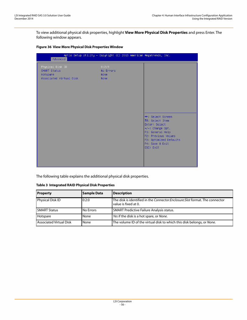
LSI Corporation- 56 -
LSI Integrated RAID SAS 3.0 Solution User GuideDecember 2014
Chapter 4: Human Interface Infrastructure Configuration ApplicationUsing the Integrated RAID Version
To view additional physical disk properties, highlight View More Physical Disk Properties and press Enter. The following window appears.
Figure 36 View More Physical Disk Properties Window
The following table explains the additional physical disk properties.
Table 3 Integrated RAID Physical Disk Properties
Property Sample Data Description
Physical Disk ID 0:2:0 The disk is identified in the Connector:Enclosure:Slot format. The connector value is fixed at 0.
SMART Status No Errors SMART Predictive Failure Analysis status.
Hotspare None Yes if the disk is a hot spare, or None.
Associated Virtual Disk None The volume ID of the virtual disk to which this disk belongs, or None.
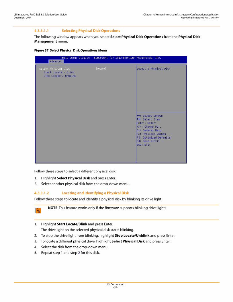
LSI Corporation- 57 -
LSI Integrated RAID SAS 3.0 Solution User GuideDecember 2014
Chapter 4: Human Interface Infrastructure Configuration ApplicationUsing the Integrated RAID Version
4.3.3.1.1 Selecting Physical Disk Operations
The following window appears when you select Select Physical Disk Operations from the Physical Disk Management menu.
Figure 37 Select Physical Disk Operations Menu
Follow these steps to select a different physical disk.
1. Highlight Select Physical Disk and press Enter. 2. Select another physical disk from the drop-down menu.
4.3.3.1.2 Locating and Identifying a Physical Disk
Follow these steps to locate and identify a physical disk by blinking its drive light.
1. Highlight Start Locate/Blink and press Enter.The drive light on the selected physical disk starts blinking.
2. To stop the drive light from blinking, highlight Stop Locate/Unblink and press Enter.3. To locate a different physical drive, highlight Select Physical Disk and press Enter.4. Select the disk from the drop-down menu.5. Repeat step 1 and step 2 for this disk.
NOTE This feature works only if the firmware supports blinking drive lights
LSI Corporation- 58 -
LSI Integrated RAID SAS 3.0 Solution User GuideDecember 2014
Appendix A: Using the SAS-3 Integrated RAID Configuration UtilityHardware and Software Requirements
Appendix A: Using the SAS-3 Integrated RAID Configuration Utility
This appendix explains how to use the command-line-driven SAS-3 Integrated RAID configuration utility (SAS3IRCU) to create and manage Integrated RAID volumes on LSI SAS-3 controllers.
You run SAS3IRCU commands from a command-line prompt or a shell script. When you use a SAS3IRCU command, the program returns a status value to the operating system when it exits.
You can use SAS3IRCU to quickly and efficiently configure Integrated RAID devices on LSI SAS-3 controllers.
A.1 Hardware and Software RequirementsSAS3IRCU runs on the following operating system architecture:
Windows®: x86, x64 (AMD64) Linux®: x86, x86_64 (supported with x86 build), PPC64 UEFI: EFI Byte Code (EBC) FreeBSD®: x86 (or i386), AMD64 (or compatible)
SAS3IRCU operates with storage devices that are compliant with existing SCSI standards.
A.1.1 Controller Support
SAS3IRCU supports the following LSI SAS-3 controllers and the host bus adapters based on these controllers:
LSISAS3008 LSISAS3004
A.1.2 Operating System and Software Support
SAS3IRCU requires PCI 2.x or PCI 3.0 firmware and MPI v2.5. SAS3IRCU supports the following operating systems.
Windows Server® 2003, Windows XP, Windows Vista®, Windows 7, Windows Server 2008, Windows Server 2008-R2, Windows 8, Windows Server 2012
UEFI 2.1 and 2.3 Linux 2.6 Kernel - Red Hat® Enterprise Linux (RHEL) 5 and higher, SUSE® Linux Enterprise Server (SLES) 10 and
higher MS-DOS® 6.22 and FreeDOS 1.0
SAS3IRCU runs on DOS only if the system BIOS supports 32-bit BIOS services, including the PCI BIOS services. SAS3IRCU uses these services to directly access the controller and its interface registers.
FreeBSD 7.2 and higher in both 32-bit and 64-bit architecture VMware® ESXi 5.0 and higher
NOTE In this appendix, the term disk means HDD and solid state drive SSD, and the HDDs or SSDs can support either SAS or SATA protocol.
NOTE LSI recommends that you use the latest version of the driver for any operating system.
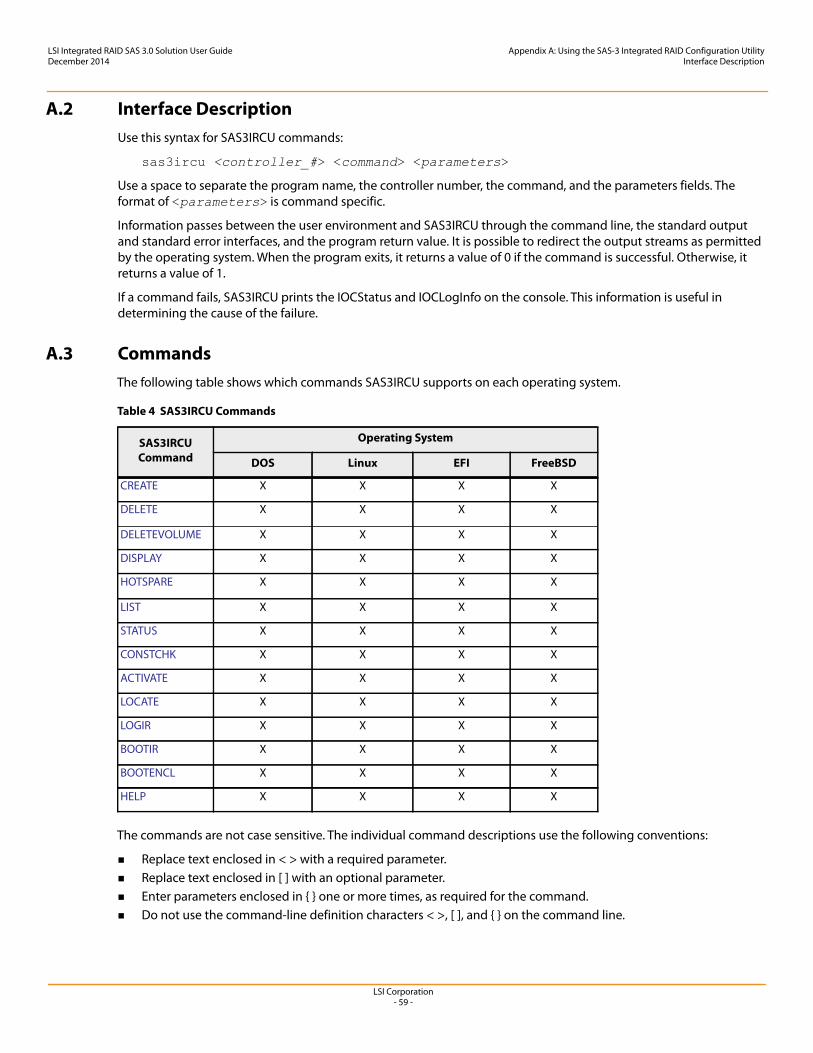
LSI Corporation- 59 -
LSI Integrated RAID SAS 3.0 Solution User GuideDecember 2014
Appendix A: Using the SAS-3 Integrated RAID Configuration UtilityInterface Description
A.2 Interface DescriptionUse this syntax for SAS3IRCU commands:
sas3ircu <controller_#> <command> <parameters>
Use a space to separate the program name, the controller number, the command, and the parameters fields. The format of <parameters> is command specific.
Information passes between the user environment and SAS3IRCU through the command line, the standard output and standard error interfaces, and the program return value. It is possible to redirect the output streams as permitted by the operating system. When the program exits, it returns a value of 0 if the command is successful. Otherwise, it returns a value of 1.
If a command fails, SAS3IRCU prints the IOCStatus and IOCLogInfo on the console. This information is useful in determining the cause of the failure.
A.3 CommandsThe following table shows which commands SAS3IRCU supports on each operating system.
The commands are not case sensitive. The individual command descriptions use the following conventions:
Replace text enclosed in < > with a required parameter. Replace text enclosed in [ ] with an optional parameter. Enter parameters enclosed in { } one or more times, as required for the command. Do not use the command-line definition characters < >, [ ], and { } on the command line.
Table 4 SAS3IRCU Commands
SAS3IRCU Command
Operating System
DOS Linux EFI FreeBSD
CREATE X X X X
DELETE X X X X
DELETEVOLUME X X X X
DISPLAY X X X X
HOTSPARE X X X X
LIST X X X X
STATUS X X X X
CONSTCHK X X X X
ACTIVATE X X X X
LOCATE X X X X
LOGIR X X X X
BOOTIR X X X X
BOOTENCL X X X X
HELP X X X X
LSI Corporation- 60 -
LSI Integrated RAID SAS 3.0 Solution User GuideDecember 2014
Appendix A: Using the SAS-3 Integrated RAID Configuration UtilityCommands
A.3.1 Common Command-Line Parameters
This section describes command-line parameters that are common to more than one command.
<controller_#>The unique controller number that the program assigns to each PCI function found on supported controller chips in the system, starting with controller # 0. For example, in a system containing two LSISAS3008 controllers, controller # 0 references the first controller and controller # 1 references the other controller. Use the LIST command to view a list of controllers connected to the system and the controller number for each controller.Valid controller number values are 0 to 255 (decimal).
<Enclosure:Bay>The enclosure and bay (or slot) of a peripheral device attached to the bus. The argument must use a colon ( : ) as a separator and must follow the Enclosure:Bay format. Enclosure is a 16-bit EnclosureHandle value set by the I/O controller (IOC). A value of 0 is invalid. Bay/Slot is a 16-bit slot value set by the IOC. Use the DISPLAY command to determine the enclosure number and slot number of a drive.
A.3.2 CREATE
The CREATE command creates Integrated RAID volumes on LSI SAS-3 controllers.
When you add a disk to an Integrated RAID volume, the volume might not use all of the disk’s storage capacity. For example, if you add a 300-GB disk drive to a volume that only uses 200 GB of capacity on each disk drive, the volume does not use the remaining 100 GB of capacity on the disk drive.
The disk identified by the first Enclosure:Bay on the command line becomes the primary disk drive when you create an Integrated Mirroring (RAID 1) volume. If the controller resynchronizes the disk drives, the data on the primary disk drive becomes available when you access the newly created volume.
When the IR firmware creates a RAID 1 volume, it starts a background initialization of the volume. Use the STATUS command to monitor the status of the initialization.
The following restrictions and defaults apply when you create Integrated RAID volumes and hot spare disks:
All disks that are part of a volume, including hot spares for that volume, must be connected to the same LSI SAS-3 controller.
The supported RAID levels are RAID 0, RAID 1, RAID 1E, and RAID 10. You can create a maximum of two Integrated RAID volumes per LSI SAS-3 controller. The maximum and minimum disk drives per RAID level are as follows:
— RAID 0: Max = 10; Min = 2.— RAID 1: Max = 2; Min = 2.— RAID 1E: Max = 10; Min = 3.— RAID 10: Max = 10; Min = 3.
SAS3IRCU does not permit you to create an Integrated RAID volume that combines SAS and SATA hard disk drives. SAS3IRCU does not permit you to create an Integrated RAID volume that combines solid-state drives (SSDs) and
hard disk drives. SAS3IRCU supports disk drives with 512-byte sectors and disk drives with 4-KB sectors. However, an Integrated
RAID volume must use all 512-byte-sector drives or all 4-KB-sector drives. You cannot combine the two types of drives in a single Integrated RAID volume.
NOTE Some operating systems do not fully support 4-KB-sector drives. Refer to the documentation for the operating system you are using.
LSI Corporation- 61 -
LSI Integrated RAID SAS 3.0 Solution User GuideDecember 2014
Appendix A: Using the SAS-3 Integrated RAID Configuration UtilityCommands
A.3.2.1 Command Linesas3ircu <controller_#> create <volume_type> <size> {<Enclosure:Bay>} [VolumeName] [noprompt]
A.3.2.2 Parameters <controller_#> – The index of the controller for the newly created volume. <volume_type> – Volume type for the new volume. Valid values are RAID0, RAID1, RAID10, or RAID1E. <size> – Size of the RAID volume in MB, or MAX for the maximum size available. <Enclosure:Bay> – The Enclosure:Bay value of the disk drive for the new RAID volume. Determine these
values from the output of the DISPLAY command. [VolumeName] – A user-specified string to identify the volume. [noprompt] – This optional parameter prevents warnings and prompts from appearing while the command is
running.
A.3.2.3 Program Return Value
0x00 SUCCESS: Command completed successfully.
0x01 FAILURE: Bad command-line arguments or operational failure.
0x02 ADAPTER_NOT_FOUND: Cannot find specified adapter.
A.3.3 DELETE
The DELETE command deletes all RAID 0, RAID 1, RAID 10, and RAID 1E Integrated RAID volumes and hot spare drives from the specified LSI SAS-3 controller. The command does not change any other controller configuration parameters.
A.3.3.1 Command Linesas3ircu <controller_#> delete [noprompt]
A.3.3.2 Parameters <controller_#> – The index of the controller with the volume or volumes that you want to delete. [noprompt] – This optional parameter prevents warnings and prompts from appearing while the command is
running.
A.3.3.3 Program Return Value
0x00 SUCCESS: Command completed successfully.
0x01 FAILURE: Bad command-line arguments or operational failure.
0x02 ADAPTER_NOT_FOUND: Cannot find specified adapter.
A.3.4 DELETEVOLUME
The DELETEVOLUME command deletes a specific RAID 0, RAID 1, RAID 10 or RAID 1E volume and the associated hot spare drives on the specified controller. The hot spare is deleted only if it is inappropriate for any of the remaining volumes. No other controller configuration parameters are changed. Use the STATUS command or the DISPLAY command to determine the volumeID of the volume you want to delete.
A.3.4.1 Command Linesas3ircu <controller_#> deletevolume <volumeID> [noprompt]
LSI Corporation- 62 -
LSI Integrated RAID SAS 3.0 Solution User GuideDecember 2014
Appendix A: Using the SAS-3 Integrated RAID Configuration UtilityCommands
A.3.4.2 Parameters <controller_#> – The index of the controller with the volume or volumes that you want to delete. <volumeID> – The volumeID of the specific IR volume that you want to delete. [noprompt] – This optional parameter prevents warnings and prompts from appearing while the command is
running.
A.3.4.3 Program Return Value
0x00 SUCCESS: Command completed successfully.
0x01 FAILURE: Bad command-line arguments or operational failure.
0x02 ADAPTER_NOT_FOUND: Cannot find specified adapter.
A.3.5 DISPLAY
The DISPLAY command displays information about LSI SAS-3 controller configurations, including controller type, firmware version, BIOS version, volume information, physical drive information, and enclosure. See the following sample output example.
The physical device information section displays the duplicate device of a dual-port SAS drive.
A.3.5.1 Command Linesas3ircu <controller_#> display [filename]
A.3.5.2 Parameters <controller_#> – The index of the controller for which you want to display information. [filename] – An optional valid filename to store the command output to a file.
A.3.5.3 Program Return Value
0x00 SUCCESS: Command completed successfully.
0x01 FAILURE: Bad command-line arguments or operational failure.
0x02 ADAPTER_NOT_FOUND: Cannot find specified adapter.
A.3.5.4 Sample Output
Following is a sample of the information that the DISPLAY command returns.
Read configuration has been initiated for controller 0------------------------------------------------------------------------Controller information------------------------------------------------------------------------ Controller type : SAS3008 PI Supports : Yes PI Mixing : Enabled BIOS version : 7.00.02.00 Firmware version : 00.250.19.0 Channel description : 1 Serial Attached SCSI Initiator ID : 112 Maximum physical devices : 62 Concurrent commands supported : 266Slot : 3Segment : 0 Bus : 64 Device : 1
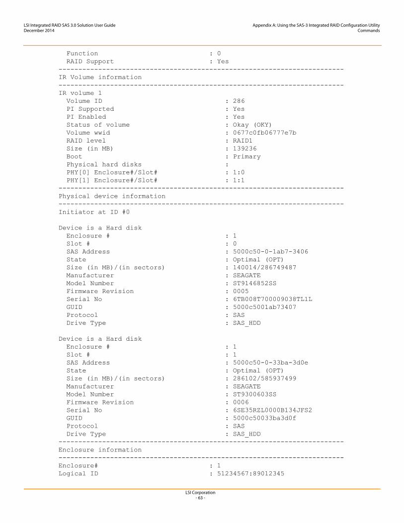
LSI Corporation- 63 -
LSI Integrated RAID SAS 3.0 Solution User GuideDecember 2014
Appendix A: Using the SAS-3 Integrated RAID Configuration UtilityCommands
Function : 0 RAID Support : Yes------------------------------------------------------------------------IR Volume information------------------------------------------------------------------------IR volume 1 Volume ID : 286 PI Supported : Yes PI Enabled : Yes Status of volume : Okay (OKY) Volume wwid : 0677c0fb06777e7b RAID level : RAID1 Size (in MB) : 139236 Boot : Primary Physical hard disks : PHY[0] Enclosure#/Slot# : 1:0 PHY[1] Enclosure#/Slot# : 1:1------------------------------------------------------------------------Physical device information------------------------------------------------------------------------Initiator at ID #0
Device is a Hard disk Enclosure # : 1 Slot # : 0 SAS Address : 5000c50-0-1ab7-3406 State : Optimal (OPT) Size (in MB)/(in sectors) : 140014/286749487 Manufacturer : SEAGATE Model Number : ST9146852SS Firmware Revision : 0005 Serial No : 6TB008T700009038TL1L GUID : 5000c5001ab73407 Protocol : SAS Drive Type : SAS_HDD
Device is a Hard disk Enclosure # : 1 Slot # : 1 SAS Address : 5000c50-0-33ba-3d0e State : Optimal (OPT) Size (in MB)/(in sectors) : 286102/585937499 Manufacturer : SEAGATE Model Number : ST9300603SS Firmware Revision : 0006 Serial No : 6SE35RZL0000B134JFS2 GUID : 5000c50033ba3d0f Protocol : SAS Drive Type : SAS_HDD------------------------------------------------------------------------Enclosure information------------------------------------------------------------------------Enclosure# : 1Logical ID : 51234567:89012345
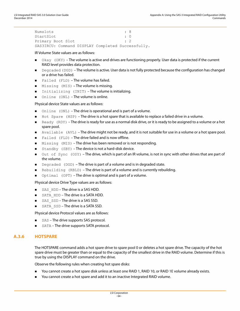
LSI Corporation- 64 -
LSI Integrated RAID SAS 3.0 Solution User GuideDecember 2014
Appendix A: Using the SAS-3 Integrated RAID Configuration UtilityCommands
Numslots : 8StartSlot : 0Primary Boot Slot : 2SAS3IRCU: Command DISPLAY Completed Successfully.
IR Volume State values are as follows:
Okay (OKY) – The volume is active and drives are functioning properly. User data is protected if the current RAID level provides data protection.
Degraded (DGD) – The volume is active. User data is not fully protected because the configuration has changed or a drive has failed.
Failed (FLD) – The volume has failed. Missing (MIS) – The volume is missing. Initializing (INIT) – The volume is initializing. Online (ONL) – The volume is online.
Physical device State values are as follows:
Online (ONL) – The drive is operational and is part of a volume. Hot Spare (HSP) – The drive is a hot spare that is available to replace a failed drive in a volume. Ready (RDY) – The drive is ready for use as a normal disk drive, or it is ready to be assigned to a volume or a hot
spare pool. Available (AVL) – The drive might not be ready, and it is not suitable for use in a volume or a hot spare pool. Failed (FLD) – The drive failed and is now offline. Missing (MIS) – The drive has been removed or is not responding. Standby (SBY) – The device is not a hard-disk device. Out of Sync (OSY) – The drive, which is part of an IR volume, is not in sync with other drives that are part of
the volume. Degraded (DGD) – The drive is part of a volume and is in degraded state. Rebuilding (RBLD) – The drive is part of a volume and is currently rebuilding. Optimal (OPT) – The drive is optimal and is part of a volume.
Physical device Drive Type values are as follows:
SAS_HDD – The drive is a SAS HDD. SATA_HDD – The drive is a SATA HDD. SAS_SSD – The drive is a SAS SSD. SATA_SSD – The drive is a SATA SSD.
Physical device Protocol values are as follows:
SAS – The drive supports SAS protocol. SATA – The drive supports SATA protocol.
A.3.6 HOTSPARE
The HOTSPARE command adds a hot spare drive to spare pool 0 or deletes a hot spare drive. The capacity of the hot spare drive must be greater than or equal to the capacity of the smallest drive in the RAID volume. Determine if this is true by using the DISPLAY command on the drive.
Observe the following rules when creating hot spare disks:
You cannot create a hot spare disk unless at least one RAID 1, RAID 10, or RAID 1E volume already exists. You cannot create a hot spare and add it to an inactive Integrated RAID volume.
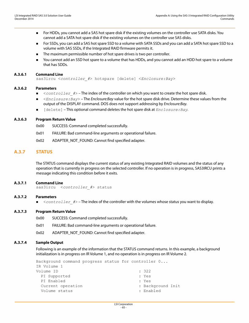
LSI Corporation- 65 -
LSI Integrated RAID SAS 3.0 Solution User GuideDecember 2014
Appendix A: Using the SAS-3 Integrated RAID Configuration UtilityCommands
For HDDs, you cannot add a SAS hot spare disk if the existing volumes on the controller use SATA disks. You cannot add a SATA hot spare disk if the existing volumes on the controller use SAS disks.
For SSDs, you can add a SAS hot spare SSD to a volume with SATA SSDs and you can add a SATA hot spare SSD to a volume with SAS SSDs, if the Integrated RAID firmware permits it.
The maximum permissible number of hot spare drives is two per controller. You cannot add an SSD hot spare to a volume that has HDDs, and you cannot add an HDD hot spare to a volume
that has SDDs.
A.3.6.1 Command Linesas3ircu <controller_#> hotspare [delete] <Enclosure:Bay>
A.3.6.2 Parameters <controller_#> – The index of the controller on which you want to create the hot spare disk. <Enclosure:Bay> – The Enclosure:Bay value for the hot spare disk drive. Determine these values from the
output of the DISPLAY command. DOS does not support addressing by Enclosure:Bay. [delete] – This optional command deletes the hot spare disk at Enclosure:Bay.
A.3.6.3 Program Return Value
0x00 SUCCESS: Command completed successfully.
0x01 FAILURE: Bad command-line arguments or operational failure.
0x02 ADAPTER_NOT_FOUND: Cannot find specified adapter.
A.3.7 STATUS
The STATUS command displays the current status of any existing Integrated RAID volumes and the status of any operation that is currently in progress on the selected controller. If no operation is in progress, SAS3IRCU prints a message indicating this condition before it exits.
A.3.7.1 Command Linesas3ircu <controller_#> status
A.3.7.2 Parameters <controller_#> – The index of the controller with the volumes whose status you want to display.
A.3.7.3 Program Return Value
0x00 SUCCESS: Command completed successfully.
0x01 FAILURE: Bad command-line arguments or operational failure.
0x02 ADAPTER_NOT_FOUND: Cannot find specified adapter.
A.3.7.4 Sample Output
Following is an example of the information that the STATUS command returns. In this example, a background initialization is in progress on IR Volume 1, and no operation is in progress on IR Volume 2.
Background command progress status for controller 0...IR Volume 1Volume ID : 322 PI Supported : Yes PI Enabled : Yes Current operation : Background Init Volume status : Enabled
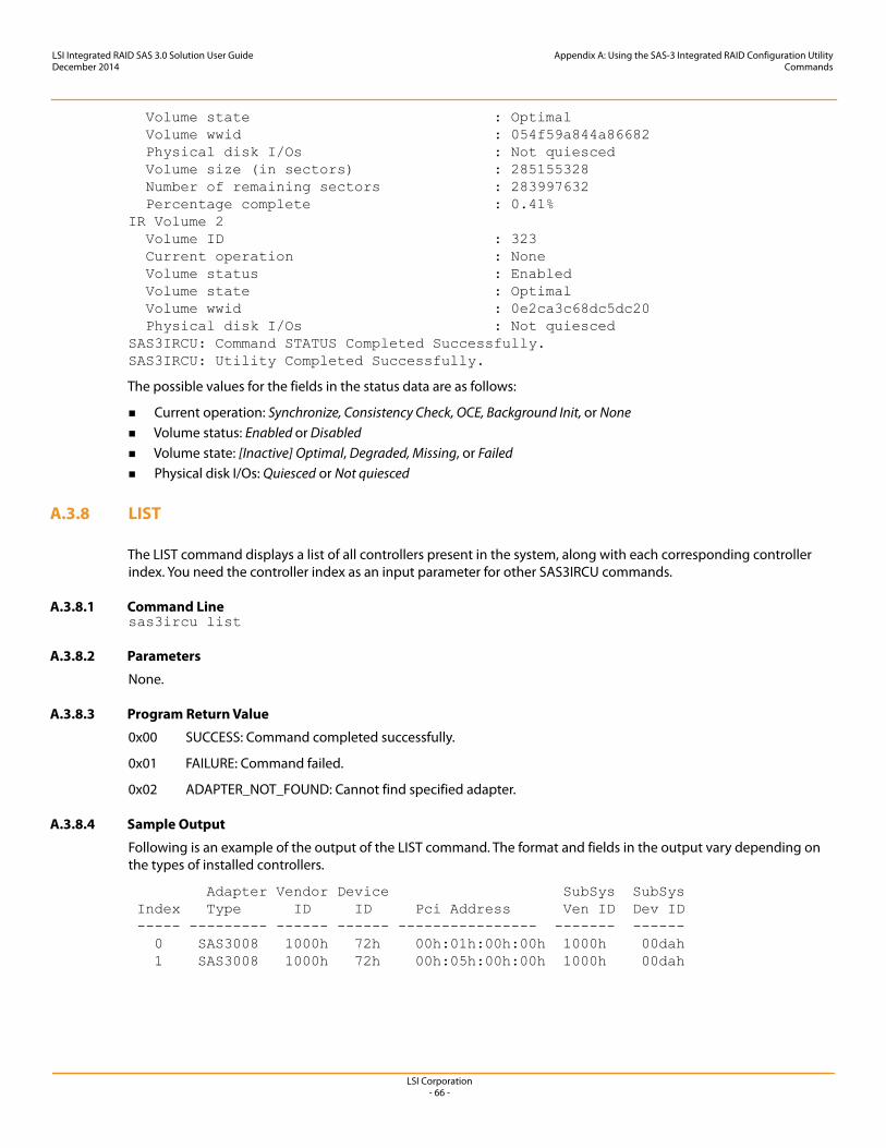
LSI Corporation- 66 -
LSI Integrated RAID SAS 3.0 Solution User GuideDecember 2014
Appendix A: Using the SAS-3 Integrated RAID Configuration UtilityCommands
Volume state : Optimal Volume wwid : 054f59a844a86682 Physical disk I/Os : Not quiesced Volume size (in sectors) : 285155328 Number of remaining sectors : 283997632 Percentage complete : 0.41%IR Volume 2 Volume ID : 323 Current operation : None Volume status : Enabled Volume state : Optimal Volume wwid : 0e2ca3c68dc5dc20 Physical disk I/Os : Not quiescedSAS3IRCU: Command STATUS Completed Successfully.SAS3IRCU: Utility Completed Successfully.
The possible values for the fields in the status data are as follows:
Current operation: Synchronize, Consistency Check, OCE, Background Init, or None Volume status: Enabled or Disabled Volume state: [Inactive] Optimal, Degraded, Missing, or Failed Physical disk I/Os: Quiesced or Not quiesced
A.3.8 LIST
The LIST command displays a list of all controllers present in the system, along with each corresponding controller index. You need the controller index as an input parameter for other SAS3IRCU commands.
A.3.8.1 Command Linesas3ircu list
A.3.8.2 Parameters
None.
A.3.8.3 Program Return Value
0x00 SUCCESS: Command completed successfully.
0x01 FAILURE: Command failed.
0x02 ADAPTER_NOT_FOUND: Cannot find specified adapter.
A.3.8.4 Sample Output
Following is an example of the output of the LIST command. The format and fields in the output vary depending on the types of installed controllers.
Adapter Vendor Device SubSys SubSys Index Type ID ID Pci Address Ven ID Dev ID ----- --------- ------ ------ ---------------- ------- ------ 0 SAS3008 1000h 72h 00h:01h:00h:00h 1000h 00dah 1 SAS3008 1000h 72h 00h:05h:00h:00h 1000h 00dah
LSI Corporation- 67 -
LSI Integrated RAID SAS 3.0 Solution User GuideDecember 2014
Appendix A: Using the SAS-3 Integrated RAID Configuration UtilityCommands
A.3.9 CONSTCHK
The CONSTCHK command requests the Integrated RAID firmware to start a consistency check operation on the specified volume.
A.3.9.1 Command Linesas3ircu <controller_#> constchk <volumeId> [noprompt]
A.3.9.2 Parameters <controller_#> – The index of the controller on which the consistency check operation runs. <volumeId> – The volume ID of an Integrated RAID volume, as listed in the DISPLAY command, on which the
consistency check operation runs. [noprompt] – This optional parameter prevents warnings and prompts from appearing while the command is
running.
A.3.9.3 Program Return Value
0x00 SUCCESS: Command completed successfully.
0x01 FAILURE: Bad command-line arguments or operational failure.
0x02 ADAPTER_NOT_FOUND: Cannot find specified adapter.
A.3.10 ACTIVATE
The ACTIVATE command activates an inactive Integrated RAID volume.
A.3.10.1 Command Linesas3ircu <controller_#> activate <volumeId>
A.3.10.2 Parameters <controller_#> – The index of the controller with the volume that requires activation. <volumeId> – The volume ID of an Integrated RAID volume currently in the Inactive state.
A.3.10.3 Program Return Value
0x00 SUCCESS: Command completed successfully.
0x01 FAILURE: Bad command-line arguments or operational failure.
0x02 ADAPTER_NOT_FOUND: Cannot find specified adapter.
A.3.11 LOCATE
The LOCATE command locates a specific drive in a volume by turning on its location indicator and flashing its LED. The command works only for drives installed in a disk enclosure. It does not work for drives attached directly to the controller.
A.3.11.1 Command Linesas3ircu <controller_#> locate <Enclosure:Bay> <action>
LSI Corporation- 68 -
LSI Integrated RAID SAS 3.0 Solution User GuideDecember 2014
Appendix A: Using the SAS-3 Integrated RAID Configuration UtilityCommands
A.3.11.2 Parameters <controller_#> – The index of the controller with the drives that you need to locate. <Enclosure:Bay> – The enclosure and bay number of the drive. <action> – The possible actions are as follows:
— ON – Turn on the location indicator of the drive.— OFF – Turn off the location indicator of the drive.
A.3.11.3 Program Return Value
0x00 SUCCESS: Command completed successfully.
0x01 FAILURE: Bad command-line arguments or operational failure.
0x02 ADAPTER_NOT_FOUND: Cannot find specified adapter.
A.3.12 LOGIR
The LOGIR command uploads or clears the Integrated RAID log information.
A.3.12.1 Command Linesas3ircu <controller_#> logir <action> [filename] [noprompt]
A.3.12.2 Parameters <controller_#> – The index of the controller with the logs that you need to upload or clear. <action> – The possible actions are as follows:
— UPLOAD – Upload the controller logs to a file.— CLEAR – Clear the controller logs.
[filename] – This optional parameter specifies the filename where the logs must be uploaded. The default filename is LOGIR.LOG.
noprompt – This optional parameter prevents warnings and prompts from appearing while the command is running.
A.3.12.3 Program Return Value
0x00 SUCCESS: Command completed successfully.
0x01 FAILURE: Bad command-line arguments or operational failure.
0x02 ADAPTER_NOT_FOUND: Cannot find specified adapter.
A.3.13 BOOTIR
The BOOTIR command selects an existing RAID volume as the primary boot device.
If an IR volume is selected as the boot device, the DISPLAY command displays this information in the IR Volume information section, if the selected IR boot volume is available to the controller. If you attempt to set a failed RAID volume as the primary boot device, the command fails with a warning message. For example, if volume 322 is in the failed state and you attempt to set it as the primary boot device, SAS3IRCU displays the following error message: SAS3IRCU: Volume specified by 322 is in Failed state!
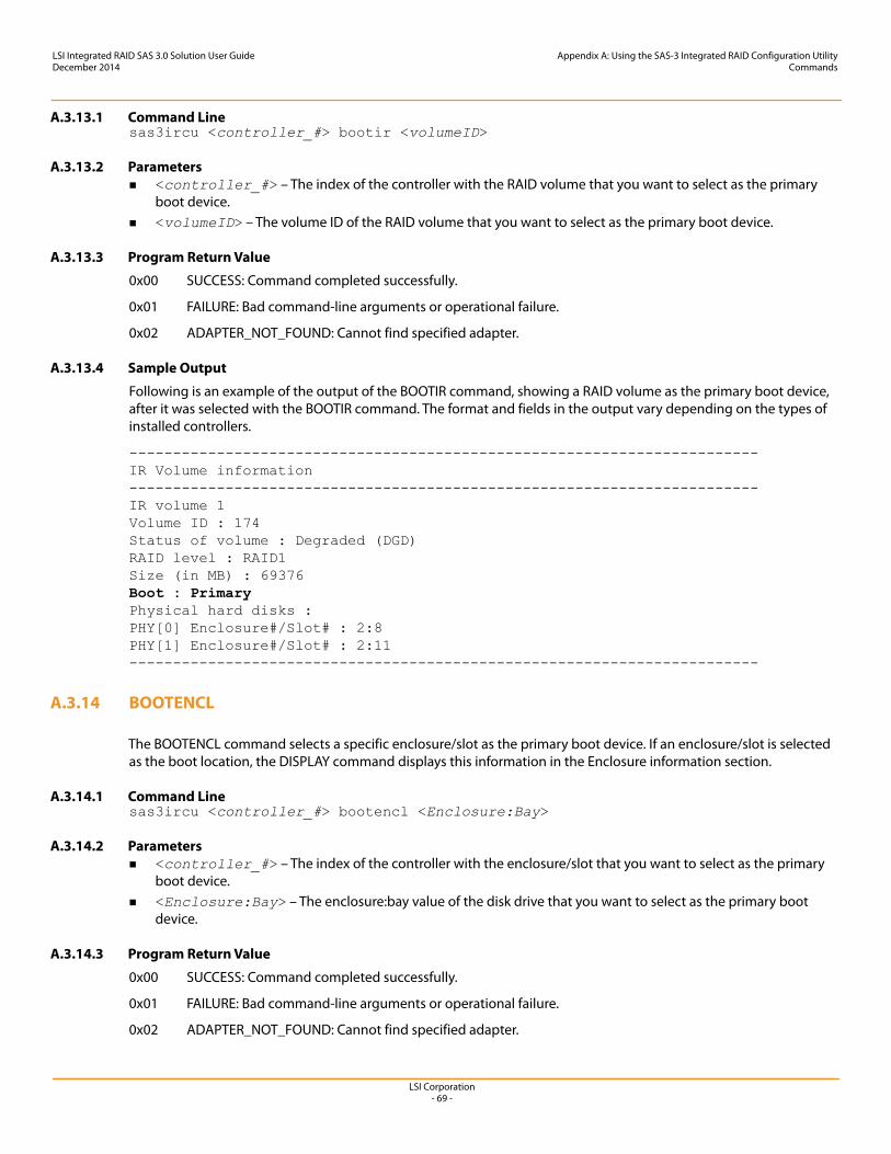
LSI Corporation- 69 -
LSI Integrated RAID SAS 3.0 Solution User GuideDecember 2014
Appendix A: Using the SAS-3 Integrated RAID Configuration UtilityCommands
A.3.13.1 Command Linesas3ircu <controller_#> bootir <volumeID>
A.3.13.2 Parameters <controller_#> – The index of the controller with the RAID volume that you want to select as the primary
boot device. <volumeID> – The volume ID of the RAID volume that you want to select as the primary boot device.
A.3.13.3 Program Return Value
0x00 SUCCESS: Command completed successfully.
0x01 FAILURE: Bad command-line arguments or operational failure.
0x02 ADAPTER_NOT_FOUND: Cannot find specified adapter.
A.3.13.4 Sample Output
Following is an example of the output of the BOOTIR command, showing a RAID volume as the primary boot device, after it was selected with the BOOTIR command. The format and fields in the output vary depending on the types of installed controllers.
------------------------------------------------------------------------ IR Volume information ------------------------------------------------------------------------ IR volume 1 Volume ID : 174 Status of volume : Degraded (DGD) RAID level : RAID1 Size (in MB) : 69376 Boot : PrimaryPhysical hard disks : PHY[0] Enclosure#/Slot# : 2:8 PHY[1] Enclosure#/Slot# : 2:11 ------------------------------------------------------------------------
A.3.14 BOOTENCL
The BOOTENCL command selects a specific enclosure/slot as the primary boot device. If an enclosure/slot is selected as the boot location, the DISPLAY command displays this information in the Enclosure information section.
A.3.14.1 Command Linesas3ircu <controller_#> bootencl <Enclosure:Bay>
A.3.14.2 Parameters <controller_#> – The index of the controller with the enclosure/slot that you want to select as the primary
boot device. <Enclosure:Bay> – The enclosure:bay value of the disk drive that you want to select as the primary boot
device.
A.3.14.3 Program Return Value
0x00 SUCCESS: Command completed successfully.
0x01 FAILURE: Bad command-line arguments or operational failure.
0x02 ADAPTER_NOT_FOUND: Cannot find specified adapter.
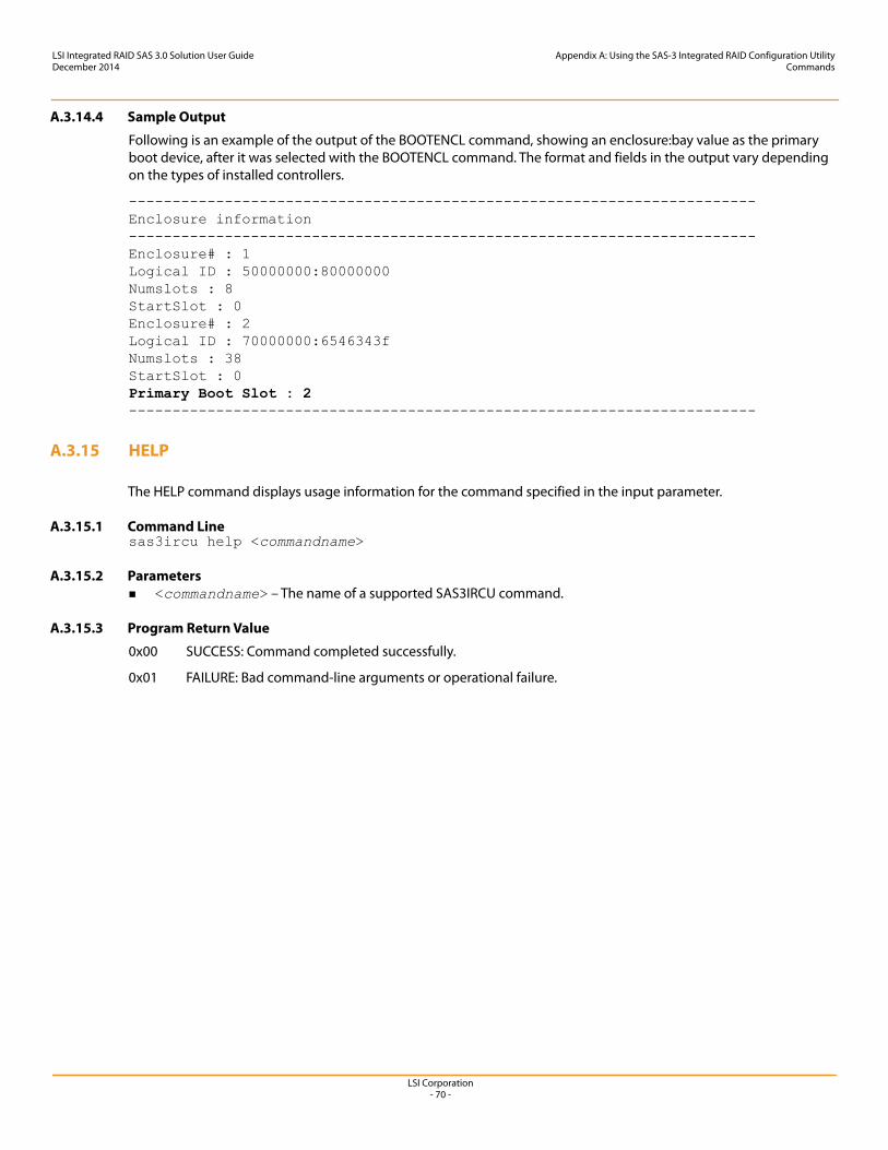
LSI Corporation- 70 -
LSI Integrated RAID SAS 3.0 Solution User GuideDecember 2014
Appendix A: Using the SAS-3 Integrated RAID Configuration UtilityCommands
A.3.14.4 Sample Output
Following is an example of the output of the BOOTENCL command, showing an enclosure:bay value as the primary boot device, after it was selected with the BOOTENCL command. The format and fields in the output vary depending on the types of installed controllers.
------------------------------------------------------------------------ Enclosure information ------------------------------------------------------------------------ Enclosure# : 1 Logical ID : 50000000:80000000 Numslots : 8 StartSlot : 0 Enclosure# : 2 Logical ID : 70000000:6546343f Numslots : 38 StartSlot : 0 Primary Boot Slot : 2------------------------------------------------------------------------
A.3.15 HELP
The HELP command displays usage information for the command specified in the input parameter.
A.3.15.1 Command Linesas3ircu help <commandname>
A.3.15.2 Parameters <commandname> – The name of a supported SAS3IRCU command.
A.3.15.3 Program Return Value
0x00 SUCCESS: Command completed successfully.
0x01 FAILURE: Bad command-line arguments or operational failure.