Embed Size (px)
Citation preview

LTE 37.901 Throughput
Sandy Fraser
April 2015
Taipei

Page
Agenda – What Factors Determine Throughput
– 37.901 General Conditions
– 37.901 Individual test case examination
– What the UXM can offer for 37.901
– Summary
September 2014 2
Page
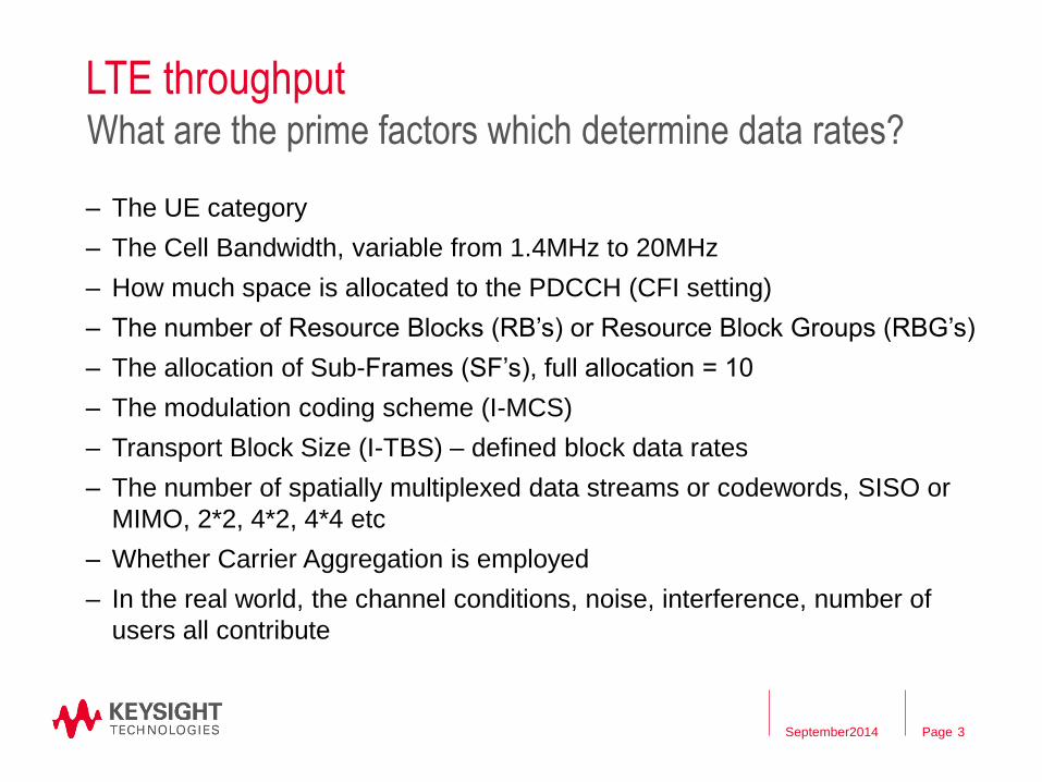
LTE throughput
– The UE category
– The Cell Bandwidth, variable from 1.4MHz to 20MHz
– How much space is allocated to the PDCCH (CFI setting)
– The number of Resource Blocks (RB’s) or Resource Block Groups (RBG’s)
– The allocation of Sub-Frames (SF’s), full allocation = 10
– The modulation coding scheme (I-MCS)
– Transport Block Size (I-TBS) – defined block data rates
– The number of spatially multiplexed data streams or codewords, SISO or
MIMO, 2*2, 4*2, 4*4 etc
– Whether Carrier Aggregation is employed
– In the real world, the channel conditions, noise, interference, number of
users all contribute
3
What are the prime factors which determine data rates?
September2014

Page
Real world Conditions affecting LTE/LTE-A device performance Channel and Network factors that impact
mobile device performance
– Fading Conditions
– Doppler Speed
– Degree of Spatial Diversity
– Noise and interference
conditions
– Transmission Mode used
– Influence of re-transmissions
and adaptive modulation and
coding
The CSI/CQI tests measure the UE’s ability to
accurately assess the channel conditions
4
Interference
Noise
Doppler
Multipath
Fading
Adaptive modulation
and coding schemes
September2014

Page
L1 and PHY versus Application Layer TPut
5
Comparison of 37.901 with 36.521 Section 8,9
36.521 S8 37.901
Channel Model Fading, Noise, OCNG Fading, Noise
Test purpose Up to MAC All Layers
Test Specifications 70% of theoretical
maximum allocation
No PASS/FAIL
Allocations FRC Follow CQI,PMI,RI
Data type Fixed MAC Padding UDP, FTP (TCP)
September2014

Page
37.901
6
Summary
– No test limits or specifications – Yet!!
– Tests for FTP/TCP and UDP
– Various fading and noise levels to force re-transmissions, rank
transitions etc
– 37.901 will NOT test fully throughput – no max data rates
– No Carrier Aggregation tests – Yet!!
– 37.901 testing is MUCH simpler with integrated fading, noise and
FTP server
September2014

Page
Agenda – What Factors Determine Throughput
– 37.901 General Conditions
– 37.901 Individual test case examination
– What the UXM can offer for 37.901
– Summary
September 2014 7

Page
37.901
8
– Definition for reference Laptop for tethered tests – no SW which
could hinder throughput
– Some statements on USB and drivers – very obvious.
– Measurement points – for either tethered or stand along UE’s
– Data rates measured without IP headers – so IP address is
important (sec 5.1.2)
– Network restrictions (laptop to be stand-alone, not connected to a
company network
key points v11.11.0 (2014-06)
September2014
Appropriate RF
connection based
upon UE receiver type
including fading and
AWGN
Application
ServerDUT
Appropriate UE to PC interface
Modem or Network Interface
Connection (NIC) and any
associated cabling as
recommeded by the UE
manufacturer for the intended
use by the customer/user
Laptop with Data
Client Test
Application
SS
RF IP

Page
37.901
– Provides application layer UE data throughput performance
measurements for both HSPA and LTE
– Only single Tx, Static Channel Uplink
– Static Channel Bi-directional Uplink and Downlink in Stress
Performance. Either:
• Bi-directional UDP or
• Alternating FTP
– No Carrier Aggregation tests
– No pass/fail verdicts, no test limits
– Defines signal levels, various noise levels, interference, various
fading profiles
9
key points v11.11.0 (2014-06)
September2014

Page
37.901
– UDP because it can be tested bi-directional without the other
direction interfering, and can be used to characterize RTP
• Downlink only, uplink only, bi-directional (concurrent)
– TCP/IP using FTP, because it effectively tests all forms of TCP/IP
underlying protocol such as SFTP and HTTP
• Downlink only, uplink only, bi-directional (concurrent and
alternating)
– SFTP, HTTP use TCP/IP so are not considered separately
– VoIP (RTP-based) has a wide variety of possible test setup’s, but in
testing UDP alone, the underlying RTP (although NOT GBR
aspects) is tested
10
key points v11.11.0 (2014-06)
September2014

Page
E7515A UXM Wireless Test Set
11
Bi-directional TCP End 2 End Carrier Aggregation Throughput
Cat 6 device with
maximum UL and DL
bi-directional TCP
Maximum DL is
290Mbps, Maximum
UL is 45Mbps
45Mbps UL
290Mbps UL
September2014

Page
37.901
12
Table 5.5.4.5-2: Test Points for LTE
Propagation
Condition
Geometry Justification
Static No interference
Note 1
To check that upper-layers do not constrain data throughput
EPA5 20dB To exhibits large TBS variations (see clause 5.5.4.3) and very
common scenarios for high-data rate requiring processing capability
EVA5 10dB EVA occurs frequently in deployments
EVA70 20 dB Adds EVA70, high SNR coverage which is common in low
frequency(<1GHz) band networks
EVA200 20 dB Covers high Doppler, high SNR scenario which is common in high
frequency (≥1GHz)band networks
ETU70 0dB Fast variations and most common high-dispersion case
ETU300 0dB A high BLER scenario may trigger higher layer retransmissions, and
also addresses the high speed scenario in the work item objective
Note 1:In the performance report, the tester shall indicate for the ‘No Interference’ condition, the
following note: In case of 'no interference', the throughput is expected to be maximal. This may
be the maximum theoretical throughput or below. In the latter case it cannot be distinguished,
whether UE limitations, or signal generator limitations with respect to EVM, or both contribute to
this.
September2014

Page
37.901 General test setup
– More common setup parameters listed in backup slides at end of
presentation
– LTE MAC - No Periodic BSR or PHR, No DRX. B.2.2.2
– LTE RLC – Acknowledged Mode only, Setup as per table 4.8.2.1.2.2-1 of TS
36.508. B.2.2.3
– LTE PDCP – No Compression. B.2.2.4
– LTE System Information as per TS36.508 section 4.4.3.4 and 4.4.3.2. B.2.2.5
– PMI is set to follow UE reports. B.2.2.6
– RI is set to follow UE reports. B.2.2.7
– CQI is set to follow the CQI reported by the UE, but the CQI to MCS mapping
can vary depending on Cell BW, and the number of antenna’s used. B.2.2.1
13
Applies to all LTE tests
September2014

Page
CQI allocation tables
CQI
Index
1.4MHz
Single
1.4MHz
Dual
3MHz
Single
3MHz
Dual
5MHz
Single
5MHz
Dual
10MHz
Single
10MHz
Dual
15MHz
Single
15MHz
Dual
20MHz
single
20MHz
Dual
0 DTX DTX DTX DTX DTX DTX DTX DTX DTX DTX DTX DTX
1 0 0 0 0 0 0 0 0 0 0 0 0
2 0 0 0 0 0 0 1 0 0 0 1 0
3 2 1 2 2 2 2 3 2 2 2 3 2
4 4 3 4 4 4 4 5 4 5 4 5 4
5 6 5 6 6 6 6 7 7 7 7 7 7
6 8 7 8 8 8 8 9 9 9 9 9 9
7 11 10 11 11 11 11 12 12 12 12 12 12
8 13 12 13 13 13 13 14 14 14 14 14 14
9 14 14 16 15 16 15 16 16 16 16 16 16
10 17 17 18 18 19 18 19 19 19 19 19 19
11 20 19 21 20 21 20 22 21 22 21 22 21
12 21 21 23 22 23 22 24 23 24 23 24 23
13 23 23 25 24 25 24 27 26 27 26 26 26
14 25 24 27 26 27 26 28 27 28 27 28 27
15 27 25 27 27 27 27 28 27 28 27 28 27
14
Depends on TM, Cell BW and antennae configuration
Amalgamation of 37.901 B.2.2.1 tables
IMCS values relate to only SF1-4,6-9 inclusive
IMCS values for SF0 and 5 must be set to DTX September2014

Page
Scheduling>Subframes Config
Manual CQI to MCS
Mapping allows non-
3GPP CQI index
settings
15 September2014

Page
Agenda – What Factors Determine Throughput
– 37.901 General Conditions
– 37.901 Individual test case examination
– What the UXM can offer for 37.901
– Summary
September 2014 16
Page
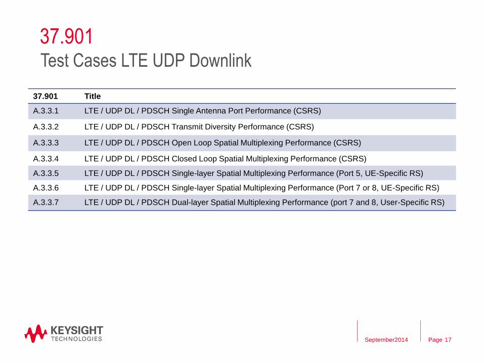
37.901
17
Test Cases LTE UDP Downlink
37.901 Title
A.3.3.1 LTE / UDP DL / PDSCH Single Antenna Port Performance (CSRS)
A.3.3.2 LTE / UDP DL / PDSCH Transmit Diversity Performance (CSRS)
A.3.3.3 LTE / UDP DL / PDSCH Open Loop Spatial Multiplexing Performance (CSRS)
A.3.3.4 LTE / UDP DL / PDSCH Closed Loop Spatial Multiplexing Performance (CSRS)
A.3.3.5 LTE / UDP DL / PDSCH Single-layer Spatial Multiplexing Performance (Port 5, UE-Specific RS)
A.3.3.6 LTE / UDP DL / PDSCH Single-layer Spatial Multiplexing Performance (Port 7 or 8, UE-Specific RS)
A.3.3.7 LTE / UDP DL / PDSCH Dual-layer Spatial Multiplexing Performance (port 7 and 8, User-Specific RS)
September2014

Page
37.901
18
Test Cases LTE FTP Downlink
37.901 Title
A.3.2.1 LTE / FTP DL / PDSCH Single Antenna Port Performance (CSRS)
A.3.2.2 LTE / FTP DL / PDSCH Transmit Diversity Performance (CSRS)
A.3.2.3 LTE / FTP DL / PDSCH Open Loop Spatial Multiplexing Performance (CSRS)
A.3.2.4 LTE / FTP DL / PDSCH Closed Loop Spatial Multiplexing Performance (CSRS)
A.3.2.5 LTE / FTP DL / PDSCH Single-layer Spatial Multiplexing Performance (Port 5, UE-Specific RS)
A.3.2.6 LTE / FTP DL / PDSCH Single-layer Spatial Multiplexing Performance (Port 7 or 8, UE-Specific RS)
A.3.2.7 LTE / FTP DL / PDSCH Dual-layer Spatial Multiplexing Performance (port 7 and 8, User-Specific RS)
September2014

Page
A.3.2.4 FTP DL Closed Loop MIMO
19
Parameter Unit All Tests
Downlink power
allocation
dB -3
dB -3 (Note 1)
at antenna port dBm/15kHz -85 (Note 2)
at antenna port dBm/15kHz -98
Transmission mode 4
Reporting periodicity ms Npd = 5
cqi-pmi-ConfigurationIndex 4
ri-ConfigurationInd 1 (Note 4)
CQI delay ms 8 for FDD
10 for TDD (Note 3)
Reporting mode PUCCH 1-1
CodeBookSubsetRestriction bitmap 111111
Note 1:
Note 2: is applied to only Test Number 1 in Table A.3.2.4.3-2: Test points for Closed Loop
SpatialMultiplexing Downlink Testing
Note 3: If the UE reports in an available uplink reporting instance at subframe SF#n based on PMI
and CQI estimation at a downlink subframe not later than SF#(n-4), this reported PMI and
wideband CQI cannot be applied at the eNB downlink before SF#(n+4).
Note 4: To avoid the ambiguity of SS behaviour when applying CQI and PMI during rank
switching, RI reports are to be applied at the SS with one subframe delay in addition to
Note 3 to align with CQI and PMI reports.
A
B
ocN
1BP
sE
Table A.3.2.4.3-1: Test Parameters for Closed Loop
Spatial Multiplexing Downlink Testing
sE
September2014
Page
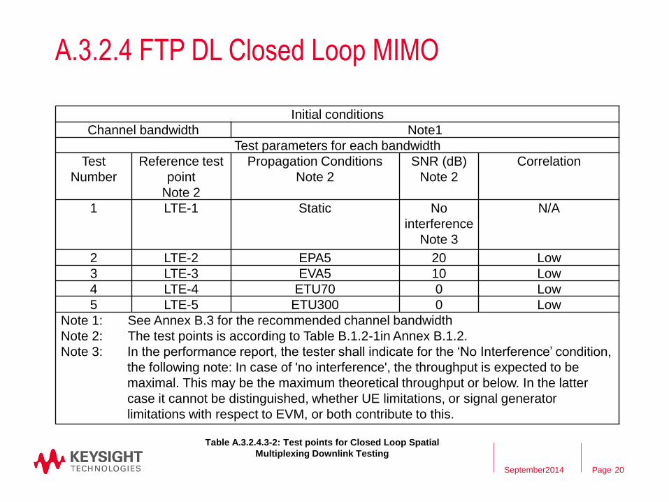
A.3.2.4 FTP DL Closed Loop MIMO
20
Initial conditions
Channel bandwidth Note1
Test parameters for each bandwidth
Test
Number
Reference test
point
Note 2
Propagation Conditions
Note 2
SNR (dB)
Note 2
Correlation
1 LTE-1 Static No
interference
Note 3
N/A
2 LTE-2 EPA5 20 Low
3 LTE-3 EVA5 10 Low
4 LTE-4 ETU70 0 Low
5 LTE-5 ETU300 0 Low
Note 1: See Annex B.3 for the recommended channel bandwidth
Note 2: The test points is according to Table B.1.2-1in Annex B.1.2.
Note 3: In the performance report, the tester shall indicate for the ‘No Interference’ condition,
the following note: In case of 'no interference', the throughput is expected to be
maximal. This may be the maximum theoretical throughput or below. In the latter
case it cannot be distinguished, whether UE limitations, or signal generator
limitations with respect to EVM, or both contribute to this.
Table A.3.2.4.3-2: Test points for Closed Loop Spatial
Multiplexing Downlink Testing
September2014

Page
A.3.2.4 FTP DL Closed Loop MIMO
• Setup the SS/OBT to respond to the UE’s reported CQI, RI and PMI
• Setup the SS/OBT for the correct BW, RMC, Fading, Noise etc
• Using the FTP client, begin FTP download from the application server of a file sufficient in
size for the test duration (60 seconds for static, 36.521 Annex G3.5 for Faded tests – 14 to
1500seconds), see 37.901 Table A.3.1-1. The faded test times vary depending on: Fading
profile, Antenna configuration, Correlation, RMC used etc.
• Note: HSPA tests use 60 seconds for static and 164s for all faded tests
• Record Throughput T result for this first iteration
• Repeat for a further 2-5 iterations
• Calculate and record the Average of the 5 iterations
• Count and record the overall number of ACK and NACK/DTX on the PUSCH/PUCCH during
the test interval.
• Repeat steps above for each subtest in Table A.3.2.4.3-2 on the previous page
• There are no pass/fail limits
21
Test process
September2014

Page
Actual 37.901 results with UXM – A.3.2.4
22
Generally flat at MAC, with
little TCP variations
No MAC re-transmissions to
give MAX Tput of 50.73Mbps
Step 1 Static No Noise, Throughput/BLER 10MHz
September2014

Page
Why 50.73Mbps and not 73.39Mbps?
August 2014 23
Effects of no SF0, 5, follow CQI and lower I-TBS
Full DL Throughput
BW 1.4 3 5 10 15 20
RBs 6 15 25 50 75 100
MAX I_MCS 28 28 28 28 28 28
MAX I_TBS 26 26 26 26 26 26
Sub-Frames 10 10 10 10 10 10
I_TBS table bits 4392 11064 18336 36696 55056 75376
Tput 1*CW 4392 11064 18336 36696 55056 75376
TPut 2*CW 8784 22128 36672 73392 110112 150752
37.901 Throughput
Max Follow I-MCS 25 27 27 27 27 27
Max Follow I_TBS 23 25 25 25 25 25
Sub-Frames 8 8 8 8 8 8
I-TBS table bits 3496 9528 15840 31704 46888 63776
Tput 1*CW 2796.8 7622.4 12672 25363.2 37510.4 51020.8
TPut 2*CW 5593.6 15244.8 25344 50726.4 75020.8 102041.6

Page
Actual 37.901 results with UXM – A.3.2.4
24
Rank 2, CQI 15, perfect
channel, no noise, maximum
throughput
No MAC re-transmissions
Step 1 Static No Noise, CSI 10MHz
September2014

Page
Actual 37.901 results with UXM – A.3.2.4
25
Highly variable
throughput and BLER,
uses all 4 transmissions
The only test step in
A.3.2.4 which really
needs averaging
Step 2 EPA5 20dB SNR, Throughput/BLER 10MHz
September2014

Page
Actual 37.901 results with UXM – A.3.2.4
26
Widely ranging
CQI, with only 1
or 2 transitions
into Rank =1
Step 2 EPA5 20dB SNR, CSI 10MHz
September2014

Page
Actual 37.901 results with UXM – A.3.2.4
27
Narrower variation
range due to more
noise, using all 4
transmissions
Step 3 EVA5 10dB SNR, Throughput/BLER 10MHz
September2014

Page
Actual 37.901 results with UXM – A.3.2.4
28
Oscillation between rank 1and 2,
two distinct groups of CQI
(10-13 Rank 1, 5-13 Rank 2)
Step 3 EVA5 10dB SNR, CSI 10MHz
September2014

Page
Actual 37.901 results with UXM – A.3.2.4
29
Tighter grouping for
BLER and CSI due to
high noise and no
Rank Transitions
Step 4 ETU70 0dB SNR, Throughput/BLER 10MHz
September2014

Page
Actual 37.901 results with UXM – A.3.2.4
30
Step 4 ETU70 0dB SNR, CSI 10MHz
Tighter grouping for
BLER and CSI due to
high noise and almost
no Rank Transitions
September2014

Page
Actual 37.901 results with UXM – A.3.2.4
31
Only slight drop in
Tput over ETU70
with same noise
Step 4 ETU300 0dB SNR, Throughput/BLER 10MHz
September2014
Page
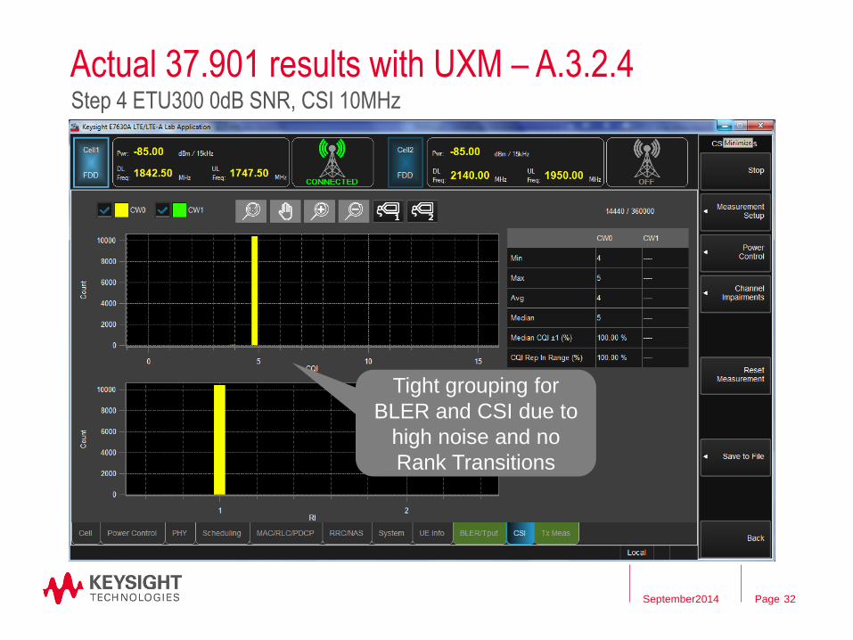
Actual 37.901 results with UXM – A.3.2.4
32
Step 4 ETU300 0dB SNR, CSI 10MHz
Tight grouping for
BLER and CSI due to
high noise and no
Rank Transitions
September2014

Page
37.901
33
Test Cases LTE UL, Stress, Power Sweep
37.901 Title
A.3.4 LTE / FTP UL / PDSCH Single Antenna Port Performance (CSRS)
A.3.5 LTE / UDP UL / PDSCH Transmit Diversity Performance (CSRS)
A.3.6.1 LTE / Stress Test Performance / PDSCH Transmit Diversity Performance (CSRS)
A.3.6.2 LTE / Stress Test Performance / PDSCH Open Loop Spatial Multiplexing Performance (CSRS)
A.3.7.1 LTE / UDP Power Sweep Performance / PDSCH Transmit Diversity Performance (CSRS)
A.3.7.2 LTE / UDP Power Sweep Performance / PDSCH Open Loop Spatial Multiplexing Performance (CSRS)
• The UL tests are very simple static channel
• Stress Tests are two single stage tests with either bi-directional UDP or
alternating direction FTP
• Power Sweep tests utilize a number of tests (N) with varying Ior values. In the
A.3.7.2 case, the Ior value decrements down in 2dB steps from -78dB to
REFSENS +6dB, all using EVA70. Ior Compensation is made for the Cell BW
September2014

Page
A.3.7.2 UDP Open Loop Power Sweep
34
Test Conditions
Parameter Unit All Tests
Downlink
power
allocation
dB -3
dB -3 (Note 1)
Transmission mode 3
Reporting interval ms 5
CQI delay ms 8
Reporting mode PUCCH 1-0
Note 1:
A
B
1BP
Table A.3.7.2.3-1: Test Parameters for Open Loop Spatial Multiplexing UDP Power Sweep Testing
Channel bandwidth
BWChannel [MHz] 1.4 3 5 10 15 20
Ior power level offset
(dB) -9.2 -5.2 -3.0 0.0 1.8 3.0
Table A.3.7.2.3-3: Ior Power level offsets for Open Loop Spatial Multiplexing UDP Power Sweep Testing
September2014

Page
A.3.7.2 UDP Open Loop Power Sweep
35
Test Conditions
Initial conditions
Channel bandwidth Note1
Test parameters for each bandwidth
Test
Number
Propagation
Conditions
Ior (dBm) Correlation
1 EVA70 -60 Low
2 EVA70 -62 Low
3 EVA70 -64 Low
4 EVA70 -66 Low
5 EVA70 -68 Low
6 EVA70 -70 Low
7 EVA70 -72 Low
8 EVA70 -74 Low
9 EVA70 -76 Low
10 EVA70 -78 Low
11 EVA70 -80 Low
12 EVA70 -82 Low
Table A.3.7.2.3-2: Test Points for Open Loop
Spatial Multiplexing UDP Power Sweep Testing
Note 1: See Annex B.3 for the recommended
channel bandwidth
Note 2: Determine if throughput increases as
the signal level is increased in relation
to the UE noise floor and remains
consistent across Ior values within a
reasonable tolerance once the
throughput has reached a maximum.
Note 3: Ior (dBm) power levels are specified for
10 MHz channel bandwidth. For other
channel bandwidths, add the offset
defined in Table A.3.7.2.3-3.
Note 4: In the performance report, the tester
shall indicate that the throughput is
expected to reach a maximum. This
may be the maximum theoretical
throughput or below. In the latter case it
cannot be distinguished, whether UE
limitations, or signal generator
limitations with respect to EVM, or both
contribute to this.
September2014

Page
A.3.7.2 UDP Open Loop Power Sweep
36
Test Process
• Setup the SS/OBT to respond to the UE’s reported CQI, RI and PMI
• Setup the SS/OBT for the correct BW, RMC, Fading profile etc
• Using the UDP client, begin UDP download for the test duration (60 seconds for static,
36.521 Annex G3.5 for Faded tests), see 37.901 Table A.3.1-1. The faded test times vary
depending on:
• Fading profile
• Antenna configuration
• Correlation
• RMC used etc
• Record Throughput T result.
• Count and record the overall number of ACK and NACK/DTX on the PUSCH/PUCCH during
the test interval.
• Repeat steps above for each subtest in Table A.3.7.2.3-2 on the previous page
• Determine if throughput increases as the signal level is increased in relation to the UE noise
floor and remains consistent across Ior values within a reasonable tolerance once the
throughput has reached a maximum.
• There are no pass/fail limits
September2014

Page
37.901
37
Test Cases LTE DL versus SNR
37.901 Title
A.3.8.1 LTE / UDP DL vs SNR PDSCH Transmit Diversity Performance (CSRS))
A.3.8.2 LTE / UDP DL vs SNR PDSCH Open Loop Spatial Multiplexing Performance (CSRS)
A.3.8.3 LTE / UDP DL vs SNR PDSCH Closed Loop Spatial Multiplexing Performance (CSRS)
A.3.8.4 LTE / UDP DL vs SNR PDSCH Single Layer Closed Loop Spatial Multiplexing Performance (CSRS)
• Each of the 4 tests above consists of either 18 or 21 separate test steps
• The test steps are in three groups using Static Channel, EPA5 or EVA70.
• Each group has several levels of Ior and SNR
September2014
Page
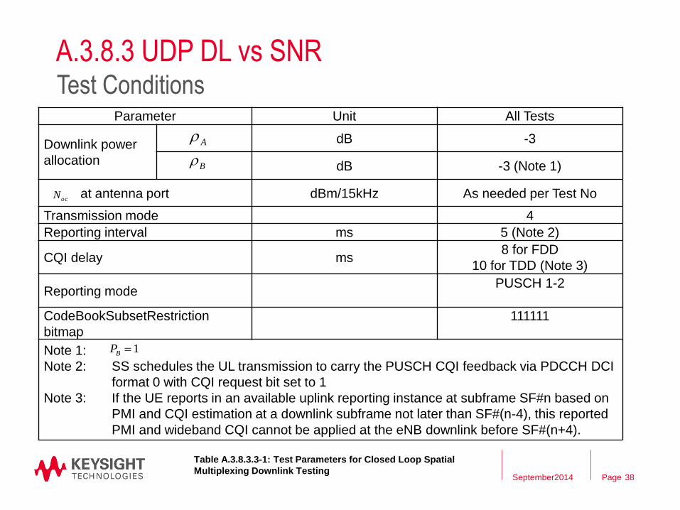
A.3.8.3 UDP DL vs SNR
38
Test Conditions Parameter Unit All Tests
Downlink power
allocation
dB -3
dB -3 (Note 1)
at antenna port dBm/15kHz As needed per Test No
Transmission mode 4
Reporting interval ms 5 (Note 2)
CQI delay ms 8 for FDD
10 for TDD (Note 3)
Reporting mode PUSCH 1-2
CodeBookSubsetRestriction
bitmap
111111
Note 1:
Note 2: SS schedules the UL transmission to carry the PUSCH CQI feedback via PDCCH DCI
format 0 with CQI request bit set to 1
Note 3: If the UE reports in an available uplink reporting instance at subframe SF#n based on
PMI and CQI estimation at a downlink subframe not later than SF#(n-4), this reported
PMI and wideband CQI cannot be applied at the eNB downlink before SF#(n+4).
A
B
ocN
1BP
Table A.3.8.3.3-1: Test Parameters for Closed Loop Spatial
Multiplexing Downlink Testing September2014

Page
A.3.8.3 UDP DL vs SNR
39
Test Conditions Initial conditions
Channel
bandwidth
Note1
Test parameters for each bandwidth
Test No Propagation
Conditions
Ior
(dBm)
SNR (dB) Correlation
1
Note 3
Static -50 No
Interference
Note 2
N/A
2 Static -55 25 N/A
3 Static -60 20 N/A
4 Static -65 15 N/A
5 Static -70 10 N/A
6 Static -75 5 N/A
7 Static -80 0 N/A
8 EPA5 -50 No External
Noise
Low
9 EPA5 -55 25 Low
10 EPA5 -60 20 Low
11 EPA5 -65 15 Low
12 EPA5 -70 10 Low
13 EPA5 -75 5 Low
14 EPA5 -80 0 Low Table A.3.8.3.3-2: Test points for Closed Loop
Spatial Multiplexing Testing
15 EVA70 -50 No
External
Noise
Low
16 EVA70 -55 25 Low
17 EVA70 -60 20 Low
18 EVA70 -65 15 Low
19 EVA70 -70 10 Low
20 EVA70 -75 5 Low
21 EVA70 -80 0 Low
Note 1: See Annex B.3 for the recommended channel
bandwidth.
Note 2: In the performance report, the tester shall indicate
for the ‘No Interference’ condition, the following
note: In case of ‘No Interference’, the throughput
is expected to be maximal. This may be the
maximum theoretical throughput or below. In the
latter case it cannot be distinguished, whether UE
limitations, or signal generator limitations with
respect to EVM, or both contribute to this.
Note 3: If this test point is part of another test there is no
need to repeat. The previous result can be used.
September2014

Page
A.3.8.3 UDP DL vs SNR
40
Test Process
• Setup the SS/OBT to respond to the UE’s reported CQI, RI and PMI
• Setup the SS/OBT for the correct BW, RMC, Fading, Noise etc, connection
diagram 36.508 Annex A, Figure A.10 (see backup slides)
• Using the UDP client, begin UDP download for the test duration (60
seconds for static, 36.521 Annex G3.5 for Faded tests), see 37.901 Table
A.3.1-1. The faded test times vary depending on:
• Fading profile
• Antenna configuration
• Correlation
• RMC used etc
• Record Throughput T result.
• Count and record the overall number of ACK and NACK/DTX on the
PUSCH/PUCCH during the test interval.
• Repeat steps above for each subtest in Table A.3.8.3.3-2 on the previous
page
• There are no pass/fail limits
September2014

Page
Agenda – What Factors Determine Throughput
– 37.901 General Conditions
– 37.901 Individual test case examination
– What the UXM can offer for 37.901
– Summary
September 2014 41

Page
E7515A UXM Wireless Test Set Carrier Aggregation end-to-end traffic
PDCP
RLC
Lower
MAC
Lower
MAC
MAC
PHY/
RF
PHY/
RF
IP
Uplink
50 Mbps
Downlink
300 Mbps
DL CC1
150
Mbps
UL
50
Mbps
L1
L2
IP
DL CC2
150
Mbps
September2014

Page
UXM CSI RRC Config Setup
43
Enable either Periodic or
Aperiodic CSI reporting with
necessary parameter and
reporting mode settings
September2014

Page
UXM – Flexible Allocations Static, Adaptive, Random PMI/RI
44
Static, Adaptive
and Random
PMI/RI allocations
Sub-frame by sub-
frame allocations
based on UE CQI
report values
Easy to eliminate
SF0 and SF5 for
testing section 8
September2014
Page
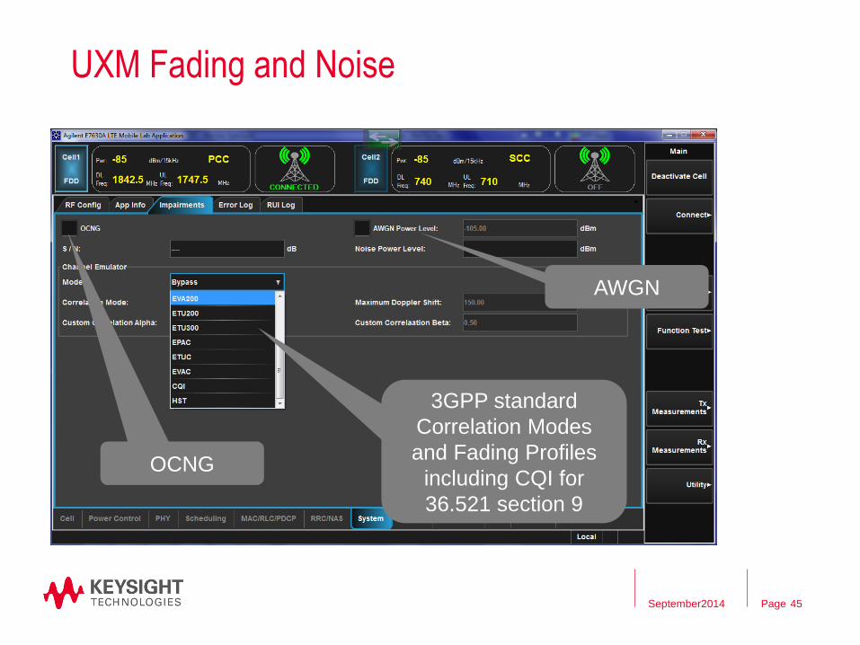
UXM Fading and Noise
AWGN
3GPP standard
Correlation Modes
and Fading Profiles
including CQI for
36.521 section 9
OCNG
45 September2014

Page
Extensive throughput testing
Easy access to
Impairments and
power control
46 September2014

Page
CSI reporting
Easy access to
Impairments and
power control
during CQI testing
PMI Codebook
selection – this
example 4*2 with
some codebook
indices deselected
47 September2014

Page
CSI reporting with Carrier Aggregation
48
Two completely
independent cells,
in this case (CA)
PCC and SCC
Results for each
Component
Carrier
Statistical results
for each codeword
September2014
Page
Agenda – What Factors Determine Throughput
– 37.901 General Conditions
– 37.901 Individual test case examination
– What the UXM can offer for 37.901
– Summary
September 2014 49

Page
L1 and PHY versus Application Layer TPut
50
Comparison of 37.901 with 36.521 Section 8,9
36.521 S8 37.901
Channel Model Fading, Noise, OCNG Fading, Noise
Test purpose Up to MAC All Layers
Test Specifications 70% of theoretical
maximum allocation
No PASS/FAIL
Allocations FRC Follow CQI,PMI,RI
Data type Fixed MAC Padding UDP, FTP (TCP)
September2014

Page
37.901
51
Summary
– No test limits or specifications – Yet!!
– Tests for FTP/TCP and UDP
– Various fading and noise levels to force re-transmissions, rank
transitions etc
– 37.901 will NOT test fully throughput – no max data rates
– No Carrier Aggregation tests – Yet!!
– 37.901 testing is MUCH simpler with integrated fading, noise and
FTP server
September2014

Page
End Main Presentation
52 September2014

Page
What next for Throughput testing?
53 September2014

Page
New UE Categories
54
Table 4.1-1 from 3GPP 36.306 up to Release 10
September2014
UE Category Maximum number of DL-SCH
transport block bits received
within a TTI (Note 1)
Maximum number of bits of a
DL-SCH transport block
received within a TTI
Total number of soft
channel bits
Maximum number of
supported layers for
spatial multiplexing in DL
Category 1 10296 10296 250368 1
Category 2 51024 51024 1237248 2
Category 3 102048 75376 1237248 2
Category 4 150752 75376 1827072 2
Category 5 299552 149776 3667200 4
Category 6 301504 149776 (4 layers)
75376 (2 layers)
3654144 2 or 4
Category 7 301504 149776 (4 layers)
75376 (2 layers)
3654144 2 or 4
Category 8 2998560 299856 35982720 8
Commercially
available UE’s NOW!
Page
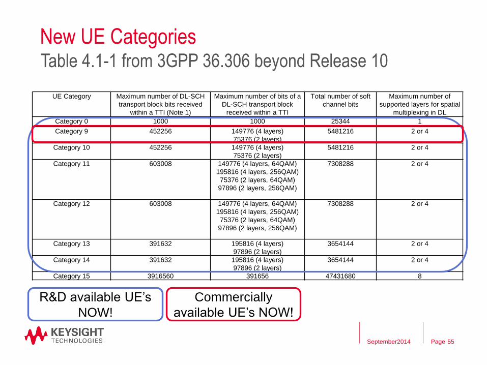
New UE Categories
55
Table 4.1-1 from 3GPP 36.306 beyond Release 10
September2014
UE Category Maximum number of DL-SCH
transport block bits received
within a TTI (Note 1)
Maximum number of bits of a
DL-SCH transport block
received within a TTI
Total number of soft
channel bits
Maximum number of
supported layers for spatial
multiplexing in DL
Category 0 1000 1000 25344 1
Category 9 452256 149776 (4 layers)
75376 (2 layers)
5481216 2 or 4
Category 10 452256 149776 (4 layers)
75376 (2 layers)
5481216 2 or 4
Category 11 603008 149776 (4 layers, 64QAM)
195816 (4 layers, 256QAM)
75376 (2 layers, 64QAM)
97896 (2 layers, 256QAM)
7308288 2 or 4
Category 12 603008 149776 (4 layers, 64QAM)
195816 (4 layers, 256QAM)
75376 (2 layers, 64QAM)
97896 (2 layers, 256QAM)
7308288 2 or 4
Category 13 391632 195816 (4 layers)
97896 (2 layers)
3654144 2 or 4
Category 14 391632 195816 (4 layers)
97896 (2 layers)
3654144 2 or 4
Category 15 3916560 391656 47431680 8
R&D available UE’s
NOW!
Commercially
available UE’s NOW!

Page
CAT 0 support for IoT
E7515A UXM
Keysight
Confidential 56
Low Power, low cost, high volume …
Release 8 CAT1 Release 12 Cat 0 Release 13
DL peak data rate 10 Mbps 1 Mbps ~200 kbps
UL peak data rate 5 Mbps 1 Mbps ~200 kbps
Max No. of spatial layers 1 1 1
No. of UE Rx chains 2 1 1
Duplex mode Full duplex Half duplex (optional) Half duplex (optional)
UE Rx bandwidth 20MHz 20MHz 1.4MHz
Max UE Tx power 23 dBm 23 dBm ~20dBm
• Low Power - Extended paging cycle and transaction cycle (not yet defined)
• Low cost - Reduced bandwidth, reduced support for DL TMs, spec relaxations (MCS support, TBS size
etc.)
• High volume - IPv6 addressing (not MSISDN), eUICC

Page
New UE Categories
57
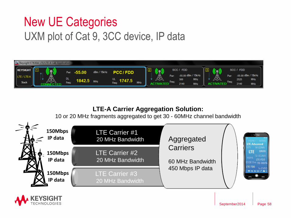
UXM plot of Cat 9, 3CC device, IP data
September2014
Page
New UE Categories
58
UXM plot of Cat 9, 3CC device, IP data
September2014
20 MHz Bandwidth
LTE Carrier #3
150Mbps IP data
LTE-A Carrier Aggregation Solution: 10 or 20 MHz fragments aggregated to get 30 - 60MHz channel bandwidth
20 MHz Bandwidth
20 MHz Bandwidth
Aggregated
Carriers LTE Carrier #2
LTE Carrier #1
60 MHz Bandwidth
450 Mbps IP data 150Mbps IP data
150Mbps IP data

Page
(F)eICIC
– Test throughput behavior in networks
employing both large and small cells
– Perform 3GPP demod performance,
UE meas, and functional performance tests,
or use custom settings to explore beyond the specs
– Designate each UXM cell as Aggressor or Victim
– Specify 36.521-1 or custom ABS patterns
– Verify FeICIC reduced power
and CRS cancellation
– Analyze data throughput
and UE meas results for
ABS, non-ABS or
combined subframes
E7515A UXM
Keysight Restricted 59
Go deeper in functional test

Page
The importance of WiFi + Mixed Aggregation
E7515A UXM
Keysight
Confidential 60
More bandwidth, more aggregation, mixed aggregation
• WiFi Offload – transfer of data from LTE to WiFi
• LTE-U in 3GPP Rel 13 is referred to as Licensed Assisted Access (LAA)
- LTE Use of 2.4 and 5GHz unlicensed spectrum, eg Bands 125, 127
- Interoperability with WiFi neighbour cells
• Inter-RAT carrier aggregation, eg LTE + WiFi
• Mixed FDD-TDD carrier aggregation
LTE WiFi
LTE licensed
WiFi, unlicensed
• LTE + WiFi aggregation
• Licensed through LTE
• LTE network control of WiFi
• Simultaneous LTE + WiFi = Wider
overall data pipe

Page
What next for Throughput testing? End
61 September2014

Page
Thank you for listening !
Any Questions ?
Page 62


![Ukrainian Defense Review #3 [July-September2014]](https://img.pdfslide.net/doc/110x75/568c54fb1a28ab4916c0f35e/ukrainian-defense-review-3-july-september2014.jpg)